EP2154513A1 - Photometric device and automatic analyzer - Google Patents
Photometric device and automatic analyzer Download PDFInfo
- Publication number
- EP2154513A1 EP2154513A1 EP08752283A EP08752283A EP2154513A1 EP 2154513 A1 EP2154513 A1 EP 2154513A1 EP 08752283 A EP08752283 A EP 08752283A EP 08752283 A EP08752283 A EP 08752283A EP 2154513 A1 EP2154513 A1 EP 2154513A1
- Authority
- EP
- European Patent Office
- Prior art keywords
- light
- light sources
- vessels
- photometric apparatus
- different wavelengths
- Prior art date
- Legal status (The legal status is an assumption and is not a legal conclusion. Google has not performed a legal analysis and makes no representation as to the accuracy of the status listed.)
- Withdrawn
Links
Images


Classifications
-
- G—PHYSICS
- G01—MEASURING; TESTING
- G01N—INVESTIGATING OR ANALYSING MATERIALS BY DETERMINING THEIR CHEMICAL OR PHYSICAL PROPERTIES
- G01N21/00—Investigating or analysing materials by the use of optical means, i.e. using sub-millimetre waves, infrared, visible or ultraviolet light
- G01N21/01—Arrangements or apparatus for facilitating the optical investigation
-
- G—PHYSICS
- G01—MEASURING; TESTING
- G01N—INVESTIGATING OR ANALYSING MATERIALS BY DETERMINING THEIR CHEMICAL OR PHYSICAL PROPERTIES
- G01N21/00—Investigating or analysing materials by the use of optical means, i.e. using sub-millimetre waves, infrared, visible or ultraviolet light
- G01N21/17—Systems in which incident light is modified in accordance with the properties of the material investigated
- G01N21/25—Colour; Spectral properties, i.e. comparison of effect of material on the light at two or more different wavelengths or wavelength bands
- G01N21/251—Colorimeters; Construction thereof
- G01N21/253—Colorimeters; Construction thereof for batch operation, i.e. multisample apparatus
-
- G—PHYSICS
- G01—MEASURING; TESTING
- G01N—INVESTIGATING OR ANALYSING MATERIALS BY DETERMINING THEIR CHEMICAL OR PHYSICAL PROPERTIES
- G01N35/00—Automatic analysis not limited to methods or materials provided for in any single one of groups G01N1/00 - G01N33/00; Handling materials therefor
- G01N35/02—Automatic analysis not limited to methods or materials provided for in any single one of groups G01N1/00 - G01N33/00; Handling materials therefor using a plurality of sample containers moved by a conveyor system past one or more treatment or analysis stations
-
- G—PHYSICS
- G01—MEASURING; TESTING
- G01N—INVESTIGATING OR ANALYSING MATERIALS BY DETERMINING THEIR CHEMICAL OR PHYSICAL PROPERTIES
- G01N35/00—Automatic analysis not limited to methods or materials provided for in any single one of groups G01N1/00 - G01N33/00; Handling materials therefor
- G01N35/02—Automatic analysis not limited to methods or materials provided for in any single one of groups G01N1/00 - G01N33/00; Handling materials therefor using a plurality of sample containers moved by a conveyor system past one or more treatment or analysis stations
- G01N35/025—Automatic analysis not limited to methods or materials provided for in any single one of groups G01N1/00 - G01N33/00; Handling materials therefor using a plurality of sample containers moved by a conveyor system past one or more treatment or analysis stations having a carousel or turntable for reaction cells or cuvettes
-
- G—PHYSICS
- G01—MEASURING; TESTING
- G01N—INVESTIGATING OR ANALYSING MATERIALS BY DETERMINING THEIR CHEMICAL OR PHYSICAL PROPERTIES
- G01N21/00—Investigating or analysing materials by the use of optical means, i.e. using sub-millimetre waves, infrared, visible or ultraviolet light
- G01N21/17—Systems in which incident light is modified in accordance with the properties of the material investigated
- G01N21/25—Colour; Spectral properties, i.e. comparison of effect of material on the light at two or more different wavelengths or wavelength bands
- G01N21/31—Investigating relative effect of material at wavelengths characteristic of specific elements or molecules, e.g. atomic absorption spectrometry
- G01N21/314—Investigating relative effect of material at wavelengths characteristic of specific elements or molecules, e.g. atomic absorption spectrometry with comparison of measurements at specific and non-specific wavelengths
- G01N2021/3181—Investigating relative effect of material at wavelengths characteristic of specific elements or molecules, e.g. atomic absorption spectrometry with comparison of measurements at specific and non-specific wavelengths using LEDs
-
- G—PHYSICS
- G01—MEASURING; TESTING
- G01N—INVESTIGATING OR ANALYSING MATERIALS BY DETERMINING THEIR CHEMICAL OR PHYSICAL PROPERTIES
- G01N2201/00—Features of devices classified in G01N21/00
- G01N2201/04—Batch operation; multisample devices
- G01N2201/0415—Carrusel, sequential
-
- G—PHYSICS
- G01—MEASURING; TESTING
- G01N—INVESTIGATING OR ANALYSING MATERIALS BY DETERMINING THEIR CHEMICAL OR PHYSICAL PROPERTIES
- G01N2201/00—Features of devices classified in G01N21/00
- G01N2201/06—Illumination; Optics
- G01N2201/062—LED's
- G01N2201/0627—Use of several LED's for spectral resolution
Definitions
- the present invention relates to a photometric apparatus and an automatic analyzer.
- Conventional automatic analyzers use photometric apparatuses that measure, using light of different wavelengths depending on what is to be measured, a reaction liquid in which a reagent and a test liquid react.
- An example of such automatic analyzers is a pre-spectroscopic automatic analyzer (e.g., see Patent Document 1) in which light sources respectively emitting light of different wavelengths and light-receiving devices are located opposing each other and along an arrangement direction. The center angles among the light sources or light-receiving devices are the same as the center angle among reaction vessels set on a cuvette wheel.
- the automatic analyzer intermittently rotates the cuvette wheel to transfer the reaction vessels, which then cut across light axes of light of different wavelengths emitted from the light sources.
- the automatic analyzer analyzes a constituent concentration and the like of a specimen.
- Patent Document 1 Japanese Utility Model Application Laid-open No. H6-19079
- FIG. 10 is a schematic diagram in which positions of the light sources L1-L5, the light-receiving devices R1-R5, and the reaction vessels C before the cuvette wheel H is rotated are viewed from the inside of the cuvette wheel H, and the reaction vessels C are arranged in a straight line.
- the cuvette wheel H in a state in FIG. 10 is rotated by one intermittent rotation in the clockwise direction, as represented by the arrow. Then, the reaction vessels C arranged on the cuvette wheel H are transferred to the right by seven units as shown in FIG. 11 .
- Nos. 1-3 reaction vessels C cross the light sources L1-L5 so that the measurement of the optical characteristics of the liquids is completed with light of different wavelengths (wavelength ⁇ 1- ⁇ 5).
- Nos. 4-7 reaction vessels C cross only some light sources emitting part of different wavelengths, and the measurement of the optical characteristics of the liquids may not be completed.
- the measurement of the optical characteristics is completed for Nos. 1-6 reaction vessels C but not completed for No.7 reaction vessel C as shown in FIG. 11 .
- An object of the present invention is to provide a photometric apparatus and an automatic analyzer with which optical characteristics of liquids contained in reaction vessels can be measured with light of different wavelengths, the reaction vessels crossing a plurality of light sources when a cuvette wheel is rotated by one intermittent rotation.
- a photometric apparatus is used in an automatic analyzer that measures an optical characteristic of liquids contained in vessels with light of different wavelengths while transferring the vessels
- the photometric apparatus includes: light sources that are arranged in a movement direction of the vessel and respectively emit light of different wavelengths; and light-receiving devices that are located opposing to the light sources with the vessel interposed inbetween and receive light of different wavelengths emitted from the light sources, wherein an arrangement length of the light sources along the movement direction of the vessel is shorter than an arrangement pitch of the vessel.
- the number of the light-receiving devices is the same as the number of the light sources.
- At least one of the light sources is located between a combination of the light sources that is specified according to a measurement item to be used for measuring the optical characteristic.
- the number of the light-receiving devices is smaller than the number of the light sources.
- the light sources are turned on on a time-division basis when light emitted from the light sources enters the same light-receiving device, so that measurement of the optical characteristic with the light of different wavelengths is completed within a period of time during which one of the vessels crosses space between the light sources and the light-receiving device.
- the light sources are semiconductor light sources.
- an automatic analyzer measures an optical characteristic of liquids contained in vessels with light of different wavelengths while transferring the vessels, and the automatic analyzer includes a photometric apparatus as described above.
- a photometric apparatus of the present invention includes a plurality of light sources that is arranged along a movement direction of vessels and emits light of different wavelengths, and a plurality of light-receiving devices that is located at opposing positions to the light sources with the vessels interposed inbetween and receives light of different wavelengths emitted from the light sources.
- the arrangement length of the light sources along the movement direction of the vessels is shorter than the arrangement pitch of the vessels.
- An automatic analyzer of the present invention includes the photometric apparatus. Therefore, the photometric apparatus and the automatic analyzer of the present invention can measure optical characteristics of liquids stored in the reaction vessels with light of different wavelengths, the reaction vessels being transferred and crossing light sources when a cuvette wheel is rotated by one intermittent rotation.
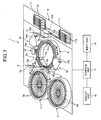
- FIG. 1 is a schematic diagram of a configuration of an automatic analyzer in accordance with a first embodiment.
- FIG. 2 is a schematic diagram illustrating a photometric apparatus of the present invention together with a cuvette wheel, a driving control unit, and a driving unit.
- an automatic analyzer 1 includes reagent tables 2 and 3, a cuvette wheel 4, a specimen-vessel transferring system 10, a photometric apparatus 13, a washing system 14, a first stirrer 15, a second stirrer 16, and a control unit 17.
- reagent vessels 2a for a first reagent and reagent vessels 3a for a second reagent are arranged along the circumferential direction.
- the reagent tables 2 and 3 are rotated by a driving unit and transfer the reagent vessels 2a and 3a in the circumferential direction.
- the reagent vessels 2a and 3a are filled with predetermined reagents corresponding to examination items.
- Identification code labels (not shown) indicating information such as a type, lot, and expiration date of a reagent are attached to the outer surface of the reagent vessels 2a and 3a.
- a reading apparatus that reads reagent information stored in the identification code labels attached to the reagent vessels 2a and 3a and outputs the reagent information to the control unit 17 is located in the outer circumference of the reagent tables 2 and 3.
- reaction vessels 5 are arranged on the cuvette wheel 4 along the circumferential direction, and the cuvette wheel 4 is intermittently rotated by a pulse motor 7b (see FIG. 2 ) in the direction shown in the arrow so as to transfer the reaction vessels 5 in the circumferential direction.
- the cuvette wheel 4 holds twenty-seven reaction vessels 5, and moves the reaction vessels 5 by seven units for one intermittent rotation, and four intermittent rotations result in "one revolution" minus "one vessel”.
- the cuvette wheel 4 includes holders that hold the reaction vessels 5, and light paths that are circle apertures through which light emitted from each LED 13b (see FIG. 3 ) in an LED array 13a is transmitted to each corresponding light-receiving device 13d (see FIG. 3 ) in a light-receiving device array 13c.
- the holders are arranged on the outer circumference of the cuvette wheel 4 along the circumferential direction at predetermined intervals.
- the holders include light paths in radial directions.
- Operations of the cuvette wheel 4 are controlled by a driving unit 7.
- the driving unit 7 includes a driving circuit 7a and the pulse motor 7b that rotates the cuvette wheel 4.
- the driving unit 7 controls the driving of the pulse motor 7b by a driving control unit 6 that uses a CPU and the like with the driving circuit 7a so that the intermittent rotation of the cuvette wheel 4 is controlled.
- FIG. 3 is a schematic diagram in which positions of the LEDs 13b and the light-receiving devices 13d constituting the photometric apparatus 13 and of the reaction vessels 5 are viewed from the inside of the cuvette wheel 4 with the reaction vessels 5 being arranged in a straight line.
- the arrow shown in FIG. 3 indicates a movement direction of the reaction vessels 5 by the rotation of the cuvette wheel 4.
- the reaction vessel 5 is a vessel called a cuvette having a rectangular cylinder shape and made of an optically transparent material that can transmit 80% or more of analysis light (e.g., 340-800 nm) emitted from the photometric apparatus 13.
- Such transparent material includes glass including heat-resistant glass, cyclic olefin, and polystyrene.
- Reagents from the reagent vessels 2a and 3a on the reagent tables 2 and 3 are dispensed into the reaction vessels 5 by reagent dispensing systems 8 and 9 that are located nearby.
- probes 8b and 9b for dispensing reagents are attached to arms 8a and 9a that are rotated in the horizontal plane in the direction along the arrow.
- the reagent dispensing systems 8 and 9 include a washing unit that washes the probes 8b and 9b using washing water.
- the specimen-vessel transferring system 10 moves and transfers arranged racks 11 one by one in the direction along the arrow.
- the rack 11 holds specimen vessels 11a that contain specimens. Every time the rack 11 transferred by the specimen vessel transferring system 10 stops moving, the specimens contained in the specimen vessels 11a are dispensed into each of the reaction vessels 5 by a specimen dispensing system 12 that includes an arm 12a that can be rotated horizontally and a probe 12b.
- the specimen dispensing system 12 includes a washing unit that washes the probe 12b using washing water.
- the photometric apparatus 13 is an optical system for analyzing a liquid sample in the reaction vessel 5 in which the reagent and the specimen have been reacted with analysis light (e.g., 340-800 nm) transmitted through the liquid sample. As shown in FIGS. 1 and 2 , the photometric apparatus 13 includes the LED array 13a, the light-receiving device array 13c, and a photometric control unit 13f.
- analysis light e.g., 340-800 nm
- the LEDs 13b each emitting light of different wavelengths (wavelengths ⁇ 1- ⁇ 5) are arranged in an array.
- the LEDs 13b are arranged in a manner such that the LEDs 13b, starting from the left to the right, emit light of the wavelength ⁇ 1, ⁇ 2, ⁇ 3, ⁇ 4, and ⁇ 5, respectively.
- length L along the arrangement direction of the LEDs 13b is shorter than the arrangement pitch P of the reaction vessels 5 so that light of different wavelengths (wavelengths ⁇ 1- ⁇ 5) crosses the liquid samples contained in the passing reaction vessels 5.
- the light-receiving devices 13d which receive light of different wavelengths emitted from the respective LEDs 13b, are located opposing to the LEDs 13b, with the reaction vessels 5 on the cuvette wheel 4 interposed inbetween.
- the light-receiving device array 13c includes a stray-light blocker 13e such as an interference filter that prevents the entering of stray light emitted from the LED 13b adjacent to the corresponding LED 13b.
- the stray-light blocker 13e is arranged on a front surface of each light-receiving device 13d, i.e., on a light-receiving side.
- the light-receiving devices 13d can be a photodiode.
- the photometric control unit 13f controls light-on of the LEDs 13b in the LED array 13a, optically measures the amount of light received by the light-receiving devices 13d, and outputs a light signal corresponding to the amount of light received to the control unit 17.
- the washing system 14 sucks out and discharges the liquid sample in the reaction vessel 5 using its nozzle 14a and then repeats the injection and suction of washing liquids such as detergents and washing water on the reaction vessel 5 using the nozzle 14a, so that the reaction vessel 5 that has been optically measured by the photometric apparatus 13 is cleaned.
- the first stirrer 15 and the second stirrer 16 stir a dispensed specimen and reagent using stir bars 15a and 16a so that the specimen and the reagent react.
- the control unit 17 includes a micro computer or the like that has calculation, memory, control, and clock functions and other functions.
- the control unit 17 is connected with the reagent tables 2 and 3, the driving control unit 6, the reagent dispensing systems 8 and 9, the specimen-vessel transferring system 10, the specimen dispensing system 12, the photometric apparatus 13, the washing system 14, the stirrers 15 and 16, an input unit 18, and a display unit 19, and the like.
- the control unit 17 controls operations of these components above and obtains light absorbance based on a light signal that is input from the photometric control unit 13f and corresponds to the amount of light received for each wavelength of light. On the basis of the light absorbance, the control unit 17 analyzes a constituent concentration and the like of a specimen.
- control unit 17 controls the automatic analyzer 1 to stop performing the analysis process or the control unit 17 gives out a warning to operators.
- the input unit 18 is used for inputting examination items and wavelengths for a photometry corresponding to the measurement item of a specimen, i.e., a specification of the LED 13b to be used, into the control unit 17.
- the input unit 18 can be a keyboard or a mouse.
- the display unit 19 is used for displaying analysis contents, analysis results, warnings, or the like.
- the display unit 19 can be a display panel or the like
- the first reagents in the reagent vessels 2a are sequentially dispensed by the reagent dispensing system 8 into the reaction vessels 5 that are transferred along the circumferential direction by the cuvette wheel 4 intermittently rotating.
- the specimens in the specimen vessels 11a held in the rack 11 are sequentially dispensed by the specimen dispensing system 12 into the reaction vessels 5.
- the reaction vessels 5 are stirred by the first stirrer 15 every time the cuvette wheel 4 stops its intermittent rotation, so that the first reagent and the specimen react.
- the second reagents in the reagent vessels 3a are sequentially dispensed by the reagent dispensing system 9 into the reaction vessels 5. Then, every time the cuvette wheel 4 stops its intermittent rotation, the reagent vessels 5 are stirred by the second stirrer 16, so that the reaction is further facilitated.
- the length L along the arrangement direction of the LEDs 13b in the LED array 13a is shorter than the arrangement pitch P of the reaction vessels 5. Therefore, when the cuvette wheel 4 is intermittently rotated in the photometric apparatus 13, all reaction vessels 5 that are transferred by seven units pass the LED array 13a.
- liquid samples contained in seven reaction vessels 5 cross light of different wavelengths (wavelengths ⁇ 1- ⁇ 5) emitted from the LEDs 13b, and therefore optical characteristics of the liquid samples are measured with the light of different wavelengths.
- the light sources and the light-receiving devices are located opposing each other and along the arrangement direction.
- the center angles among the light sources are the same as the center angles among the reaction vessels set on the cuvette wheel.
- all seven reaction vessels 5 transferred by one intermittent rotation can be measured with light of different wavelengths.
- the photometric apparatus 13 uses a semiconductor light source, i.e., LED, as a light source. In this manner, the photometric apparatus 13 itself can be downsized and also the cuvette wheel 4 can be downsized, which allows the automatic analyzer 1 as a whole to be downsized.
- the automatic analyzer 1 measures optical characteristics of a liquid sample contained in the reaction vessel 5 with combinations of light of two different wavelengths based on measurement items. For example, suppose that combinations of light of two different wavelengths for measurements are ( ⁇ 1, ⁇ 2), ( ⁇ 2, ⁇ 3), ( ⁇ 3, ⁇ 4), and ( ⁇ 4, ⁇ 5).
- combinations of light of two different wavelengths for measurements are ( ⁇ 1, ⁇ 2), ( ⁇ 2, ⁇ 3), ( ⁇ 3, ⁇ 4), and ( ⁇ 4, ⁇ 5).
- the LED array 13a in FIG. 4 where the LEDs 13b are arranged in a way that the wavelengths of emitted light are ⁇ 1, ⁇ 2,..., ⁇ 5 light emitted from an adjacent LED 13b can possibly enter the light-receiving device 13d that is not at the opposition position as stray light.
- the LEDs 13b in the LED array 13a are arranged in a manner such that the LEDs 13b, starting from the left to the right, emit light of the wavelength ⁇ 1, ⁇ 4, ⁇ 2, ⁇ 5, and ⁇ 3, respectively, as shown in FIG. 5 .
- at least one light source that is not used for a measurement is located between a combination of light sources used for the measurement.
- FIG. 6 is a schematic diagram in which positions of LEDs and light-receiving devices constituing a photometric apparatus and of reaction vessels are viewed from the inside of a cuvette wheel with the reaction vessels being arranged in a straight line.
- an automatic analyzer in accordance with the second embodiment or other embodiments described later has substantially the same configuration as the automatic analyzer and the photometric apparatus in accordance with the first embodiment, and the same components have the same numerals.
- a photometric apparatus 20 in accordance with the second embodiment includes the LED array 13a, the light-receiving device array 13c, and the photometric control unit 13f.
- the LED array 13a is the light-receiving device array 13c shown in FIG. 5 where the LEDs 13b emit, starting from the left to the right, light of wavelengths ⁇ 1, ⁇ 4, ⁇ 2, ⁇ 5, and ⁇ 3, respectively.
- the light-receiving device array 13c includes three light-receiving devices 13d: the light-receiving device 13d that is located opposing the LED 13b emitting light of wavelength ⁇ 1, the light-receiving device 13d that is located opposing to the LEDs 13b emitting light of wavelengths ⁇ 4 and ⁇ 2, and the light-receiving device 13d that is located opposing to the LEDs 13b emitting light of wavelengths ⁇ 5 and ⁇ 3.
- the photometric apparatus 20 measures optical characteristics of liquid samples contained in the reaction vessels 5 with combinations of light of two different wavelengths ( ⁇ 1, ⁇ 2), ( ⁇ 2, ⁇ 3), ( ⁇ 3, ⁇ 4), and ( ⁇ 4, ⁇ 5).
- the photometric apparatus 20 measures optical characteristics of liquid samples, light of two different wavelengths never enters the same light-receiving device 13d simultaneously.
- the photometric apparatus 20 can measure optical characteristics of liquid samples with three light-receiving devices 13d, meaning that the number of light-receiving devices can be reduced.
- at least one light source not being used for a measurement of optical characteristics is located between two LEDs 13b being used for the measurement (being light-on), and the space between two LEDs 13b becomes wider.
- FIG. 7 is a schematic diagram in which positions of LEDs and light-receiving devices constituting a photometric apparatus in accordance with a third embodiment, and of reaction vessels are viewed from the inside of a cuvette wheel with the reaction vessels being arranged in a straight line.
- FIG. 8 is a diagram illustrating a light-on timing of two light sources used for measuring optical characteristics during one light-on cycle.
- a photometric apparatus 25 in accordance with the third embodiment includes the LED array 13a, the light-receiving device 13d, and the photometric control unit 13f.
- the photometric control unit 13f controls the LED array 13a and turns on light of five LEDs 13b on a time-division basis.
- the photometric control unit 13f controls light-on (ON or OFF) of the LEDs 13b emitting light of wavelength ⁇ 1 and the LED 13b emitting light of wavelength ⁇ 2 in one light-on cycle T. Meanwhile, the photometric control unit 13f keeps the other three LEDs 13b respectively emitting light of wavelengths ⁇ 3- ⁇ 5 OFF.
- the photometric apparatus 25 turns on the LEDs 13b used for measuring optical characteristics on a time-division basis, and the number of light-receiving devices can be reduced to be one.
- the number of reagent tables may be one.
- a reagent vessel for the first reagent and a reagent vessel for the second reagent may be located on the one reagent table, or one type of a reagent vessel may be located on each reagent table.
- the automatic analyzer described above uses a semiconductor light source as an LED
- the automatic analyzer may use a semiconductor laser.
- the embodiment does not limit the number of reaction vessels 5 that cross the light emitted by the LED array 13a when the cuvette wheel 4 is intermittently rotated one revolution and does not limit the number of LEDs 13b and light-receiving devices 13d constituting the photometric apparatus.
- the photometric apparatus and the automatic analyzer of the present invention is useful for measuring optical characteristics of liquids contained in reaction vessels with the light of different wavelengths, the reaction vessels crossing light sources when a cuvette wheel is intermittently rotated once.
Landscapes
- Chemical & Material Sciences (AREA)
- Physics & Mathematics (AREA)
- Biochemistry (AREA)
- Life Sciences & Earth Sciences (AREA)
- Health & Medical Sciences (AREA)
- Analytical Chemistry (AREA)
- General Health & Medical Sciences (AREA)
- General Physics & Mathematics (AREA)
- Immunology (AREA)
- Pathology (AREA)
- Spectroscopy & Molecular Physics (AREA)
- Chemical Kinetics & Catalysis (AREA)
- Automatic Analysis And Handling Materials Therefor (AREA)
- Investigating Or Analysing Materials By Optical Means (AREA)
- Investigating Or Analysing Materials By The Use Of Chemical Reactions (AREA)
Abstract
Description
- The present invention relates to a photometric apparatus and an automatic analyzer.
- Conventional automatic analyzers use photometric apparatuses that measure, using light of different wavelengths depending on what is to be measured, a reaction liquid in which a reagent and a test liquid react. An example of such automatic analyzers is a pre-spectroscopic automatic analyzer (e.g., see Patent Document 1) in which light sources respectively emitting light of different wavelengths and light-receiving devices are located opposing each other and along an arrangement direction. The center angles among the light sources or light-receiving devices are the same as the center angle among reaction vessels set on a cuvette wheel. The automatic analyzer intermittently rotates the cuvette wheel to transfer the reaction vessels, which then cut across light axes of light of different wavelengths emitted from the light sources. On the basis of the light absorbance of the reaction liquid, the automatic analyzer analyzes a constituent concentration and the like of a specimen.
- Patent Document 1: Japanese Utility Model Application Laid-open No.
H6-19079 - In the pre-spectroscopic automatic analyzer disclosed in
Patent Document 1, light is dispersed into light of different wavelengths and then emitted from the light sources. When the automatic analyzer inPatent Document 1 intermittently rotates the cuvette wheel, a problem occurs in that some reaction vessels cut across only light axes of light of different wavelengths emitted from part of light sources. For example, in a photometric apparatus shown inFIG. 9 , light sources L1-L5 respectively emit light (of wavelengths λ1-λ5), and light transmitted through a liquid contained in a reaction vessel C is received by the light-receiving devices R1-R5. - In the photometric apparatus shown in
FIG. 9 , suppose, for convenience of the description, that Nos. 1-27 are attached to reaction vessels C and arranged in the counterclockwise direction, that the 27 reaction vessels C are arranged on a cuvette wheel H, and that one intermittent rotation transfers a portion of the reaction vessels, i.e., seven reaction vessels C. Considering the rotation direction of the cuvette wheel H, No. 1 reaction vessel C is positioned right in front of the light source L1 and the light-receiving device R1.FIG. 10 is a schematic diagram in which positions of the light sources L1-L5, the light-receiving devices R1-R5, and the reaction vessels C before the cuvette wheel H is rotated are viewed from the inside of the cuvette wheel H, and the reaction vessels C are arranged in a straight line. - To measure optical characteristics of liquids contained in the reaction vessels C, the cuvette wheel H in a state in
FIG. 10 is rotated by one intermittent rotation in the clockwise direction, as represented by the arrow. Then, the reaction vessels C arranged on the cuvette wheel H are transferred to the right by seven units as shown inFIG. 11 . As a result, Nos. 1-3 reaction vessels C cross the light sources L1-L5 so that the measurement of the optical characteristics of the liquids is completed with light of different wavelengths (wavelength λ1-λ5). Nos. 4-7 reaction vessels C, however, cross only some light sources emitting part of different wavelengths, and the measurement of the optical characteristics of the liquids may not be completed. - For example, when the light sources L1 and L2 and the light-receiving devices R1 and R2 are used to take a measurement, the measurement of the optical characteristics is completed for Nos. 1-6 reaction vessels C but not completed for No.7 reaction vessel C as shown in
FIG. 11 . - The present invention is made in view of the above. An object of the present invention is to provide a photometric apparatus and an automatic analyzer with which optical characteristics of liquids contained in reaction vessels can be measured with light of different wavelengths, the reaction vessels crossing a plurality of light sources when a cuvette wheel is rotated by one intermittent rotation.
- To solve the problem as described above and to achieve an object, a photometric apparatus according to the present invention is used in an automatic analyzer that measures an optical characteristic of liquids contained in vessels with light of different wavelengths while transferring the vessels, and the photometric apparatus includes: light sources that are arranged in a movement direction of the vessel and respectively emit light of different wavelengths; and light-receiving devices that are located opposing to the light sources with the vessel interposed inbetween and receive light of different wavelengths emitted from the light sources, wherein an arrangement length of the light sources along the movement direction of the vessel is shorter than an arrangement pitch of the vessel.
- Further, in a photometric apparatus according to the present invention, the number of the light-receiving devices is the same as the number of the light sources.
- Further, in a photometric apparatus according to the present invention, at least one of the light sources is located between a combination of the light sources that is specified according to a measurement item to be used for measuring the optical characteristic.
- Further, in a photometric apparatus according to the present invention, the number of the light-receiving devices is smaller than the number of the light sources.
- Further, in a photometric apparatus according to the present invention, the light sources are turned on on a time-division basis when light emitted from the light sources enters the same light-receiving device, so that measurement of the optical characteristic with the light of different wavelengths is completed within a period of time during which one of the vessels crosses space between the light sources and the light-receiving device.
- Further, in a photometric apparatus according to the present invention, the light sources are semiconductor light sources.
- Still further, to solve the problem as described above and to achieve an object, an automatic analyzer according to the present invention measures an optical characteristic of liquids contained in vessels with light of different wavelengths while transferring the vessels, and the automatic analyzer includes a photometric apparatus as described above.
- A photometric apparatus of the present invention includes a plurality of light sources that is arranged along a movement direction of vessels and emits light of different wavelengths, and a plurality of light-receiving devices that is located at opposing positions to the light sources with the vessels interposed inbetween and receives light of different wavelengths emitted from the light sources. The arrangement length of the light sources along the movement direction of the vessels is shorter than the arrangement pitch of the vessels. An automatic analyzer of the present invention includes the photometric apparatus. Therefore, the photometric apparatus and the automatic analyzer of the present invention can measure optical characteristics of liquids stored in the reaction vessels with light of different wavelengths, the reaction vessels being transferred and crossing light sources when a cuvette wheel is rotated by one intermittent rotation.
-
-
FIG. 1 is a schematic diagram of a configuration of an automatic analyzer in accordance with a first embodiment; -
FIG. 2 is a schematic diagram illustrating a photometric apparatus of the present invention together with a cuvette wheel, a driving control unit, and a driving unit; -
FIG. 3 is a schematic diagram in which positions of LEDs and light-receiving devices constituting a photometric apparatus and of reaction vessels are viewed from an inside of a cuvette wheel with the reaction vessels being arranged in a straight line; -
FIG. 4 is a diagram illustrating an arrangement order of wavelengths of light of different wavelengths emitted by LEDs constituting an LED array; -
FIG. 5 is a diagram illustrating another arrangement order of wavelengths of light of different wavelengths emitted by LEDs constituting an LED array; -
FIG. 6 is a schematic diagram in which positions of LEDs and light-receiving devices constituting a photometric apparatus in accordance with a second embodiment and of reaction vessels are viewed from the inside of a cuvette wheel with the reaction vessels being arranged in a straight line; -
FIG. 7 is a schematic diagram in which positions of LEDs and light-receiving devices constituting a photometric apparatus in accordance with a third embodiment, and of reaction vessels are viewed from the inside of a cuvette wheel with the reaction vessels being arranged in a straight line; -
FIG. 8 is a diagram illustrating the light-on timing of two light sources used for measuring optical characteristics during one light-on cycle; -
FIG. 9 is a schematic diagram of a cuvette wheel and an analysis optical system for illustrating a measurement method of a conventional photometric apparatus; -
FIG. 10 is a schematic diagram in which positions of LEDs and light-receiving devices constituting the photometric apparatus shown inFIG. 9 and of reaction vessels are viewed from the inside of a cuvette wheel with the reaction vessels being arranged in a straight line; and -
FIG. 11 is a schematic diagram illustrating a state after a cuvette wheel in a state inFIG. 10 is intermittently rotated. -
- 1
- Automatic analyzer
- 2, 3
- Reagent table
- 4
- Cuvette wheel
- 5
- Reaction vessel
- 6
- Driving control unit
- 7
- Driving unit
- 7a
- Driving circuit
- 7b
- Pulse motor
- 8, 9
- Reagent dispensing system
- 10
- Specimen-vessel transferring system
- 11
- Rack
- 11a
- Specimen vessel
- 12
- Specimen dispensing system
- 13
- Photometric apparatus
- 13a
- LED array
- 13b
- LED
- 13c
- Light-receiving device array
- 13d
- Light-receiving device
- 13e
- Stray-light blocker
- 13f
- Photometric control unit
- 14
- Washing system
- 15, 16
- Stirrer
- 17
- Control unit
- 18
- Input unit
- 19
- Display unit
- P
- Arrangement pitch of reaction vessel
- A photometric apparatus and an automatic analyzer in accordance with a first embodiment of the present invention are described in detail with reference to drawings.
FIG. 1 is a schematic diagram of a configuration of an automatic analyzer in accordance with a first embodiment.FIG. 2 is a schematic diagram illustrating a photometric apparatus of the present invention together with a cuvette wheel, a driving control unit, and a driving unit. - As shown in
FIG. 1 , anautomatic analyzer 1 includes reagent tables 2 and 3, acuvette wheel 4, a specimen-vessel transferring system 10, aphotometric apparatus 13, awashing system 14, afirst stirrer 15, asecond stirrer 16, and acontrol unit 17. - As shown in
FIG. 1 , in the reagent tables 2 and 3,reagent vessels 2a for a first reagent andreagent vessels 3a for a second reagent are arranged along the circumferential direction. The reagent tables 2 and 3 are rotated by a driving unit and transfer thereagent vessels reagent vessels reagent vessels reagent vessels control unit 17 is located in the outer circumference of the reagent tables 2 and 3. - As shown in
FIG. 1 ,reaction vessels 5 are arranged on thecuvette wheel 4 along the circumferential direction, and thecuvette wheel 4 is intermittently rotated by apulse motor 7b (seeFIG. 2 ) in the direction shown in the arrow so as to transfer thereaction vessels 5 in the circumferential direction. For example, as shown inFIG. 2 , thecuvette wheel 4 holds twenty-sevenreaction vessels 5, and moves thereaction vessels 5 by seven units for one intermittent rotation, and four intermittent rotations result in "one revolution" minus "one vessel". Thecuvette wheel 4 includes holders that hold thereaction vessels 5, and light paths that are circle apertures through which light emitted from eachLED 13b (seeFIG. 3 ) in anLED array 13a is transmitted to each corresponding light-receivingdevice 13d (seeFIG. 3 ) in a light-receivingdevice array 13c. - The holders are arranged on the outer circumference of the
cuvette wheel 4 along the circumferential direction at predetermined intervals. The holders include light paths in radial directions. Operations of thecuvette wheel 4 are controlled by adriving unit 7. As shown inFIG. 2 , the drivingunit 7 includes a drivingcircuit 7a and thepulse motor 7b that rotates thecuvette wheel 4. The drivingunit 7 controls the driving of thepulse motor 7b by a drivingcontrol unit 6 that uses a CPU and the like with the drivingcircuit 7a so that the intermittent rotation of thecuvette wheel 4 is controlled. -
FIG. 3 is a schematic diagram in which positions of theLEDs 13b and the light-receivingdevices 13d constituting thephotometric apparatus 13 and of thereaction vessels 5 are viewed from the inside of thecuvette wheel 4 with thereaction vessels 5 being arranged in a straight line. The arrow shown inFIG. 3 indicates a movement direction of thereaction vessels 5 by the rotation of thecuvette wheel 4. - The
reaction vessel 5 is a vessel called a cuvette having a rectangular cylinder shape and made of an optically transparent material that can transmit 80% or more of analysis light (e.g., 340-800 nm) emitted from thephotometric apparatus 13. Such transparent material includes glass including heat-resistant glass, cyclic olefin, and polystyrene. Reagents from thereagent vessels reaction vessels 5 byreagent dispensing systems reagent dispensing systems arms reagent dispensing systems probes - As shown in
FIG. 1 , the specimen-vessel transferring system 10 moves and transfers arrangedracks 11 one by one in the direction along the arrow. Therack 11 holdsspecimen vessels 11a that contain specimens. Every time therack 11 transferred by the specimenvessel transferring system 10 stops moving, the specimens contained in thespecimen vessels 11a are dispensed into each of thereaction vessels 5 by aspecimen dispensing system 12 that includes anarm 12a that can be rotated horizontally and aprobe 12b. Thespecimen dispensing system 12 includes a washing unit that washes theprobe 12b using washing water. - The
photometric apparatus 13 is an optical system for analyzing a liquid sample in thereaction vessel 5 in which the reagent and the specimen have been reacted with analysis light (e.g., 340-800 nm) transmitted through the liquid sample. As shown inFIGS. 1 and2 , thephotometric apparatus 13 includes theLED array 13a, the light-receivingdevice array 13c, and aphotometric control unit 13f. - As shown in
FIGS. 3 and4 , in theLED array 13a, theLEDs 13b each emitting light of different wavelengths (wavelengths λ1-λ5) are arranged in an array. TheLEDs 13b are arranged in a manner such that theLEDs 13b, starting from the left to the right, emit light of the wavelength λ1, λ2, λ3, λ4, and λ5, respectively. Furthermore, as shown inFIG. 3 , in theLED array 13a, length L along the arrangement direction of theLEDs 13b is shorter than the arrangement pitch P of thereaction vessels 5 so that light of different wavelengths (wavelengths λ1-λ5) crosses the liquid samples contained in the passingreaction vessels 5. - In the light-receiving
device array 13c, the light-receivingdevices 13d, which receive light of different wavelengths emitted from therespective LEDs 13b, are located opposing to theLEDs 13b, with thereaction vessels 5 on thecuvette wheel 4 interposed inbetween. The light-receivingdevice array 13c includes a stray-light blocker 13e such as an interference filter that prevents the entering of stray light emitted from theLED 13b adjacent to thecorresponding LED 13b. The stray-light blocker 13e is arranged on a front surface of each light-receivingdevice 13d, i.e., on a light-receiving side. For example, the light-receivingdevices 13d can be a photodiode. - The
photometric control unit 13f controls light-on of theLEDs 13b in theLED array 13a, optically measures the amount of light received by the light-receivingdevices 13d, and outputs a light signal corresponding to the amount of light received to thecontrol unit 17. - The
washing system 14 sucks out and discharges the liquid sample in thereaction vessel 5 using itsnozzle 14a and then repeats the injection and suction of washing liquids such as detergents and washing water on thereaction vessel 5 using thenozzle 14a, so that thereaction vessel 5 that has been optically measured by thephotometric apparatus 13 is cleaned. - The
first stirrer 15 and thesecond stirrer 16 stir a dispensed specimen and reagent usingstir bars - The
control unit 17 includes a micro computer or the like that has calculation, memory, control, and clock functions and other functions. Thecontrol unit 17 is connected with the reagent tables 2 and 3, the drivingcontrol unit 6, thereagent dispensing systems vessel transferring system 10, thespecimen dispensing system 12, thephotometric apparatus 13, thewashing system 14, thestirrers input unit 18, and adisplay unit 19, and the like. Thecontrol unit 17 controls operations of these components above and obtains light absorbance based on a light signal that is input from thephotometric control unit 13f and corresponds to the amount of light received for each wavelength of light. On the basis of the light absorbance, thecontrol unit 17 analyzes a constituent concentration and the like of a specimen. Furthermore, when it is determined that the lot of the reagent is different or that the expiration date has expired on the basis of information read from data on the identification-code label attached to thereagent vessels control unit 17 controls theautomatic analyzer 1 to stop performing the analysis process or thecontrol unit 17 gives out a warning to operators. - The
input unit 18 is used for inputting examination items and wavelengths for a photometry corresponding to the measurement item of a specimen, i.e., a specification of theLED 13b to be used, into thecontrol unit 17. For example, theinput unit 18 can be a keyboard or a mouse. Thedisplay unit 19 is used for displaying analysis contents, analysis results, warnings, or the like. Thedisplay unit 19 can be a display panel or the like - In the
automatic analyzer 1 configured as above, the first reagents in thereagent vessels 2a are sequentially dispensed by thereagent dispensing system 8 into thereaction vessels 5 that are transferred along the circumferential direction by thecuvette wheel 4 intermittently rotating. After the first reagents are dispensed into thereaction vessels 5, the specimens in thespecimen vessels 11a held in therack 11 are sequentially dispensed by thespecimen dispensing system 12 into thereaction vessels 5. After the specimens are dispensed into thereaction vessels 5, thereaction vessels 5 are stirred by thefirst stirrer 15 every time thecuvette wheel 4 stops its intermittent rotation, so that the first reagent and the specimen react. After the first reagent and the specimen are stirred, the second reagents in thereagent vessels 3a are sequentially dispensed by thereagent dispensing system 9 into thereaction vessels 5. Then, every time thecuvette wheel 4 stops its intermittent rotation, thereagent vessels 5 are stirred by thesecond stirrer 16, so that the reaction is further facilitated. - With the
photometric apparatus 13, the length L along the arrangement direction of theLEDs 13b in theLED array 13a is shorter than the arrangement pitch P of thereaction vessels 5. Therefore, when thecuvette wheel 4 is intermittently rotated in thephotometric apparatus 13, allreaction vessels 5 that are transferred by seven units pass theLED array 13a. Thus, with thephotometric apparatus 13, liquid samples contained in sevenreaction vessels 5 cross light of different wavelengths (wavelengths λ1-λ5) emitted from theLEDs 13b, and therefore optical characteristics of the liquid samples are measured with the light of different wavelengths. - In conventional automatic analyzers, the light sources and the light-receiving devices are located opposing each other and along the arrangement direction. The center angles among the light sources are the same as the center angles among the reaction vessels set on the cuvette wheel. In contrast, in the
automatic analyzer 1, all sevenreaction vessels 5 transferred by one intermittent rotation can be measured with light of different wavelengths. Furthermore, thephotometric apparatus 13 uses a semiconductor light source, i.e., LED, as a light source. In this manner, thephotometric apparatus 13 itself can be downsized and also thecuvette wheel 4 can be downsized, which allows theautomatic analyzer 1 as a whole to be downsized. - In general, the
automatic analyzer 1 measures optical characteristics of a liquid sample contained in thereaction vessel 5 with combinations of light of two different wavelengths based on measurement items. For example, suppose that combinations of light of two different wavelengths for measurements are (λ1, λ2), (λ2, λ3), (λ3, λ4), and (λ4, λ5). In this case, in theLED array 13a inFIG. 4 where theLEDs 13b are arranged in a way that the wavelengths of emitted light are λ1, λ2,..., λ5, light emitted from anadjacent LED 13b can possibly enter the light-receivingdevice 13d that is not at the opposition position as stray light. - In order to prevent the entering of such stray light, the
LEDs 13b in theLED array 13a are arranged in a manner such that theLEDs 13b, starting from the left to the right, emit light of the wavelength λ1, λ4, λ2, λ5, and λ3, respectively, as shown inFIG. 5 . In this manner, at least one light source that is not used for a measurement is located between a combination of light sources used for the measurement. With thephotometric apparatus 13 where theLEDs 13b are arranged as described, the measurement of optical characteristics is not affected by stray light, and therefore analysis accuracy of theautomatic analyzer 1 is improved. - A photometric apparatus and an automatic analyzer in accordance with a second embodiment of the present invention are described in detail with reference to drawings. In the photometric apparatus in accordance with the first embodiment, the number of light sources is the same as the number of light-receiving devices. In contrast, in a photometric apparatus in accordance with the second embodiment, the number of light-receiving devices is smaller than the number of light sources.
FIG. 6 is a schematic diagram in which positions of LEDs and light-receiving devices constituing a photometric apparatus and of reaction vessels are viewed from the inside of a cuvette wheel with the reaction vessels being arranged in a straight line. Although the configuration of the photometric apparatus differs depending on the parts, an automatic analyzer in accordance with the second embodiment or other embodiments described later has substantially the same configuration as the automatic analyzer and the photometric apparatus in accordance with the first embodiment, and the same components have the same numerals. - As shown in
FIG. 6 , aphotometric apparatus 20 in accordance with the second embodiment includes theLED array 13a, the light-receivingdevice array 13c, and thephotometric control unit 13f. TheLED array 13a is the light-receivingdevice array 13c shown inFIG. 5 where theLEDs 13b emit, starting from the left to the right, light of wavelengths λ1, λ4, λ2, λ5, and λ3, respectively. The light-receivingdevice array 13c includes three light-receivingdevices 13d: the light-receivingdevice 13d that is located opposing theLED 13b emitting light of wavelength λ1, the light-receivingdevice 13d that is located opposing to theLEDs 13b emitting light of wavelengths λ4 and λ2, and the light-receivingdevice 13d that is located opposing to theLEDs 13b emitting light of wavelengths λ5 and λ3. Thephotometric apparatus 20 measures optical characteristics of liquid samples contained in thereaction vessels 5 with combinations of light of two different wavelengths (λ1, λ2), (λ2, λ3), (λ3, λ4), and (λ4, λ5). - When the
photometric apparatus 20 measures optical characteristics of liquid samples, light of two different wavelengths never enters the same light-receivingdevice 13d simultaneously. In addition to the advantage provided in the first embodiment, thephotometric apparatus 20 can measure optical characteristics of liquid samples with three light-receivingdevices 13d, meaning that the number of light-receiving devices can be reduced. Furthermore, of fiveLEDs 13b, at least one light source not being used for a measurement of optical characteristics (not being light-on) is located between twoLEDs 13b being used for the measurement (being light-on), and the space between twoLEDs 13b becomes wider. Therefore, with thephotometric apparatus 20, light emitted from theLEDs 13b enters only light-receivingdevices 13d located at opposing positions, and light emitted fromother LEDs 13b does not enter the light-receivingdevices 13d as stray light. As a result, photometry accuracy is improved. - A photometric apparatus and an automatic analyzer in accordance with a third embodiment of the present invention are described in detail with reference to drawings. A photometric apparatus in accordance with the second embodiment uses five light sources and three light-receiving devices. In contrast, a photometric apparatus in accordance with the third embodiment uses one light-receiving device.
FIG. 7 is a schematic diagram in which positions of LEDs and light-receiving devices constituting a photometric apparatus in accordance with a third embodiment, and of reaction vessels are viewed from the inside of a cuvette wheel with the reaction vessels being arranged in a straight line.FIG. 8 is a diagram illustrating a light-on timing of two light sources used for measuring optical characteristics during one light-on cycle. - As shown in
FIG. 7 , aphotometric apparatus 25 in accordance with the third embodiment includes theLED array 13a, the light-receivingdevice 13d, and thephotometric control unit 13f. When optical characteristics of liquid samples contained in thereaction vessels 5 are measured, thephotometric control unit 13f controls theLED array 13a and turns on light of fiveLEDs 13b on a time-division basis. - For example, when the
photometric apparatus 25 measures optical characteristics of liquid samples contained in thereaction vessels 5 with a combination of light of two optical wavelengths (λ1, λ2), thephotometric control unit 13f controls light-on (ON or OFF) of theLEDs 13b emitting light of wavelength λ1 and theLED 13b emitting light of wavelength λ2 in one light-on cycle T. Meanwhile, thephotometric control unit 13f keeps the other threeLEDs 13b respectively emitting light of wavelengths λ3-λ5 OFF. - In addition to the advantage provided in the first embodiment, the
photometric apparatus 25 turns on theLEDs 13b used for measuring optical characteristics on a time-division basis, and the number of light-receiving devices can be reduced to be one. - Although the automatic analyzer described above uses two reagent tables and two types of reagents, the number of reagent tables may be one. A reagent vessel for the first reagent and a reagent vessel for the second reagent may be located on the one reagent table, or one type of a reagent vessel may be located on each reagent table.
- Furthermore, although the automatic analyzer described above uses a semiconductor light source as an LED, the automatic analyzer may use a semiconductor laser. Furthermore, the embodiment does not limit the number of
reaction vessels 5 that cross the light emitted by theLED array 13a when thecuvette wheel 4 is intermittently rotated one revolution and does not limit the number ofLEDs 13b and light-receivingdevices 13d constituting the photometric apparatus. - As described above, the photometric apparatus and the automatic analyzer of the present invention is useful for measuring optical characteristics of liquids contained in reaction vessels with the light of different wavelengths, the reaction vessels crossing light sources when a cuvette wheel is intermittently rotated once.
Claims (7)
- A photometric apparatus that is used in an automatic analyzer that measures an optical characteristic of liquids contained in vessels with light of different wavelengths while transferring the vessels, the photometric apparatus comprising:light sources that are arranged in a movement direction of the vessel and respectively emit light of different wavelengths; andlight-receiving devices that are located opposing to the light sources with the vessel interposed inbetween and receive light of different wavelengths emitted from the light sources, whereinan arrangement length of the light sources along the movement direction of the vessel is shorter than an arrangement pitch of the vessel.
- The photometric apparatus according to claim 1, wherein
the number of the light-receiving devices is the same as the number of the light sources. - The photometric apparatus according to claim 1, wherein
at least one of the light sources is located between a combination of the light sources that is specified according to a measurement item to be used for measuring the optical characteristic. - The photometric apparatus according to claim 1, wherein
the number of the light-receiving devices is smaller than the number of the light sources. - The photometric apparatus according to claim 4, wherein
the light sources are turned on on a time-division basis when light emitted from the light sources enters the same light-receiving device, so that measurement of the optical characteristic with the light of different wavelengths is completed within a period of time during which one of the vessels crosses space between the light sources and the light-receiving device. - The photometric apparatus according to claim 1, wherein
the light sources are semiconductor light sources. - An automatic analyzer that measures an optical characteristic of liquids contained in vessels with light of different wavelengths while transferring the vessels, the automatic analyzer comprising:the photometric apparatus according to any one of claims 1 to 6.
Applications Claiming Priority (2)
| Application Number | Priority Date | Filing Date | Title |
|---|---|---|---|
| JP2007124678A JP2008281392A (en) | 2007-05-09 | 2007-05-09 | Photometric apparatus and automatic analysis apparatus |
| PCT/JP2008/058364 WO2008139954A1 (en) | 2007-05-09 | 2008-05-01 | Photometric device and automatic analyzer |
Publications (2)
| Publication Number | Publication Date |
|---|---|
| EP2154513A1 true EP2154513A1 (en) | 2010-02-17 |
| EP2154513A4 EP2154513A4 (en) | 2011-11-23 |
Family
ID=40002162
Family Applications (1)
| Application Number | Title | Priority Date | Filing Date |
|---|---|---|---|
| EP08752283A Withdrawn EP2154513A4 (en) | 2007-05-09 | 2008-05-01 | Photometric device and automatic analyzer |
Country Status (6)
| Country | Link |
|---|---|
| US (1) | US8064062B2 (en) |
| EP (1) | EP2154513A4 (en) |
| JP (1) | JP2008281392A (en) |
| KR (1) | KR101126479B1 (en) |
| CN (1) | CN101680834B (en) |
| WO (1) | WO2008139954A1 (en) |
Cited By (2)
| Publication number | Priority date | Publication date | Assignee | Title |
|---|---|---|---|---|
| EP2762887A4 (en) * | 2011-09-27 | 2015-06-03 | Shenzhen Yhlo Biotech Co Ltd | FULLY AUTOMATIC IMMUNITY ANALYZER AND DETECTION METHOD THEREOF |
| EP4249919A1 (en) * | 2022-03-21 | 2023-09-27 | Absology Co., Ltd. | Automatic immunoassay system |
Families Citing this family (20)
| Publication number | Priority date | Publication date | Assignee | Title |
|---|---|---|---|---|
| WO2012077536A1 (en) * | 2010-12-08 | 2012-06-14 | 株式会社日立ハイテクノロジーズ | Automatic analytical apparatus |
| US9395240B2 (en) * | 2011-05-04 | 2016-07-19 | Siemens Healthcare Diagnostics Inc. | Methods, systems, and apparatus for biological sample illumination at multiple wavelengths |
| CN103063588B (en) * | 2011-10-20 | 2015-04-01 | 光宝科技股份有限公司 | Optical detection device and optical measurement system |
| US20140271369A1 (en) * | 2013-03-15 | 2014-09-18 | Abbott Laboratories | System and Method for Processing Both Clinical Chemistry and Immunoassay Tests |
| JP6261945B2 (en) * | 2013-10-29 | 2018-01-17 | 東芝メディカルシステムズ株式会社 | Automatic analyzer |
| KR102161058B1 (en) * | 2013-12-24 | 2020-09-29 | 삼성전자주식회사 | Optical detection apparatus and method of compensating detection error |
| US9492357B2 (en) * | 2014-04-11 | 2016-11-15 | DoseSmart, Inc. | Personal intelligent dispenser |
| US10730687B2 (en) * | 2014-10-16 | 2020-08-04 | RxCap Inc. | Intelligent medicine dispenser |
| CN104865202A (en) * | 2015-05-23 | 2015-08-26 | 深圳德夏生物医学工程有限公司 | Single-channel biochemical and specific protein analyzer provided with full-wavelength rotary lamp discs and silicon photocells |
| CN104880413A (en) * | 2015-05-23 | 2015-09-02 | 深圳德夏生物医学工程有限公司 | Multichannel biochemistry and specific protein analyzer with full wavelength light source and spectrometer |
| CN113702269B (en) * | 2016-01-21 | 2024-04-09 | 东京毅力科创株式会社 | Chemical solution supply device and coating and developing system |
| CN112014581B (en) | 2017-07-14 | 2024-07-09 | 迈恩医疗解决方案有限公司 | Automated analyzer and method for performing chemical, biochemical and/or immunochemical analysis |
| US11635443B2 (en) | 2017-07-14 | 2023-04-25 | Meon Medical Solutions Gmbh & Co Kg | Automatic analyzer and method for carrying out chemical, biochemical, and/or immunochemical analyses |
| KR102069337B1 (en) * | 2018-02-09 | 2020-01-22 | 단국대학교 천안캠퍼스 산학협력단 | Real-time monitoring device for quantitative nucleic acid measurement using isothermal amplification |
| CN112004604B (en) | 2018-04-23 | 2023-02-03 | 迈恩医疗解决方案有限公司 | Optical measuring unit and optical measuring method for obtaining a measuring signal of a fluid medium |
| CN112041076B (en) * | 2018-04-23 | 2023-04-18 | 迈恩医疗解决方案有限公司 | Automatic analyzer and optical measuring method for obtaining a measuring signal from a liquid medium |
| CN109490321B (en) * | 2018-11-27 | 2021-10-01 | 河南敏涵化妆品有限公司 | A light-transmitting cosmetic solution impurity detection device |
| JP7300826B2 (en) * | 2018-12-05 | 2023-06-30 | 株式会社日立製作所 | Analysis device and analysis method |
| KR102814300B1 (en) | 2020-12-04 | 2025-05-28 | 주식회사 엘지화학 | Light stability evaluation apparatus of materials for organic layer of organic light emitting device and evaluation method thereof |
| US20260060892A1 (en) * | 2024-08-29 | 2026-03-05 | Chalie Kaye Mackey | Provider-Controlled Medication Dispenser and Methods of Use Thereof |
Family Cites Families (20)
| Publication number | Priority date | Publication date | Assignee | Title |
|---|---|---|---|---|
| JPS57132038A (en) * | 1981-02-10 | 1982-08-16 | Olympus Optical Co Ltd | Photometric device |
| AU553772B2 (en) * | 1981-07-20 | 1986-07-24 | American Hospital Supply Corp. | Cuvette system for automated chemical analyzer |
| JPS5970946A (en) * | 1982-10-15 | 1984-04-21 | Toshiba Corp | Apparatus for measuring absorbance |
| US4762413A (en) * | 1984-09-07 | 1988-08-09 | Olympus Optical Co., Ltd. | Method and apparatus for measuring immunological reaction with the aid of fluctuation in intensity of scattered light |
| US4980292A (en) * | 1984-10-01 | 1990-12-25 | Baxter International Inc. | Tablet dispensing |
| US4695727A (en) * | 1986-03-07 | 1987-09-22 | Nicolet Instrument Corporation | Optical analytical instrument with automatic sample changing |
| JPH0619079Y2 (en) * | 1988-04-28 | 1994-05-18 | オリンパス光学工業株式会社 | Spectrometer in automatic analyzer |
| FR2634893B1 (en) * | 1988-07-28 | 1990-09-14 | Guigan Jean | MINIATURE LABORATORY FOR CARRYING OUT BIOLOGICAL ANALYSIS BY CHEMICAL REACTION FROM A BLOOD SAMPLE |
| JP2834200B2 (en) * | 1989-08-02 | 1998-12-09 | 株式会社日立製作所 | Liquid sample analyzer and analysis method |
| JPH0477669A (en) * | 1990-07-20 | 1992-03-11 | Nittec Co Ltd | Automatic analyzer |
| JPH05157684A (en) * | 1991-12-02 | 1993-06-25 | Seikagaku Kogyo Co Ltd | Absorptiometer |
| JPH08122247A (en) * | 1994-10-24 | 1996-05-17 | Hitachi Ltd | Analysis equipment |
| US6195158B1 (en) * | 1995-11-21 | 2001-02-27 | Cme Telemetrix Inc. | Apparatus and method for rapid spectrophotometric pre-test screen of specimen for a blood analyzer |
| JPH1080416A (en) * | 1996-09-09 | 1998-03-31 | Hitachi Ltd | Non-invasive biochemical measurement device |
| JPH10115583A (en) * | 1996-10-11 | 1998-05-06 | Kubota Corp | Spectrometer |
| JP3524419B2 (en) * | 1999-03-08 | 2004-05-10 | アロカ株式会社 | Absorbance measurement device |
| EP1128185B8 (en) * | 2000-02-25 | 2009-08-19 | Hitachi, Ltd. | Mixing device for automatic analyzer |
| JP2002267595A (en) * | 2001-03-07 | 2002-09-18 | Dkk Toa Corp | Compact multi-component detector |
| CN1588089A (en) * | 2004-09-03 | 2005-03-02 | 上海艾诺电子有限公司 | Automatic loading and unloading system for full automatic biochemical analyzer clorimetric cup and its control method |
| JP3980031B2 (en) * | 2005-02-09 | 2007-09-19 | 株式会社日立製作所 | Automatic analyzer |
-
2007
- 2007-05-09 JP JP2007124678A patent/JP2008281392A/en not_active Withdrawn
-
2008
- 2008-05-01 KR KR1020097023232A patent/KR101126479B1/en not_active Expired - Fee Related
- 2008-05-01 CN CN2008800152717A patent/CN101680834B/en not_active Expired - Fee Related
- 2008-05-01 EP EP08752283A patent/EP2154513A4/en not_active Withdrawn
- 2008-05-01 WO PCT/JP2008/058364 patent/WO2008139954A1/en not_active Ceased
-
2009
- 2009-11-05 US US12/613,422 patent/US8064062B2/en not_active Expired - Fee Related
Cited By (2)
| Publication number | Priority date | Publication date | Assignee | Title |
|---|---|---|---|---|
| EP2762887A4 (en) * | 2011-09-27 | 2015-06-03 | Shenzhen Yhlo Biotech Co Ltd | FULLY AUTOMATIC IMMUNITY ANALYZER AND DETECTION METHOD THEREOF |
| EP4249919A1 (en) * | 2022-03-21 | 2023-09-27 | Absology Co., Ltd. | Automatic immunoassay system |
Also Published As
| Publication number | Publication date |
|---|---|
| EP2154513A4 (en) | 2011-11-23 |
| CN101680834A (en) | 2010-03-24 |
| US8064062B2 (en) | 2011-11-22 |
| WO2008139954A1 (en) | 2008-11-20 |
| KR101126479B1 (en) | 2012-03-29 |
| CN101680834B (en) | 2011-09-14 |
| KR20100017097A (en) | 2010-02-16 |
| US20100045994A1 (en) | 2010-02-25 |
| JP2008281392A (en) | 2008-11-20 |
Similar Documents
| Publication | Publication Date | Title |
|---|---|---|
| US8064062B2 (en) | Photometric apparatus and automatic analyzer | |
| US20240272186A1 (en) | Automatic analyzer | |
| EP2116850A1 (en) | Analyzer | |
| US9778274B2 (en) | Automatic analyzer | |
| JP2007322324A (en) | Analyzer | |
| JP2007322287A (en) | Autoanalyer | |
| JPWO2008139978A1 (en) | Photometric method of automatic analyzer and automatic analyzer | |
| JP5264851B2 (en) | Automatic analyzer and reagent management method | |
| JP2007322246A (en) | Autoanalyzer | |
| JP5739236B2 (en) | Automatic analyzer | |
| WO2021044656A1 (en) | Complex-type auto analysis device, system, and abnormality determination method | |
| JP6675226B2 (en) | Automatic analyzer | |
| JP2010145377A (en) | Automatic analyzer and photometry thereof | |
| JP4871152B2 (en) | Automatic analyzer | |
| JP6523807B2 (en) | Automatic analyzer | |
| WO2013021646A1 (en) | Analytical instrument and analysis method | |
| JP2024082548A (en) | Transport rack, automatic analyzer, and automatic analysis system | |
| EP2154512A1 (en) | Automated analyzer | |
| JP2007315786A (en) | Autoanalyzer | |
| JP2009180676A (en) | Analyzing apparatus | |
| JP2008122316A (en) | Autoanalyzer, and calibration curve display method for the autoanalyzer | |
| JP7490671B2 (en) | Automated Analysis Equipment | |
| JP2007285920A (en) | Analyzer | |
| JP4753645B2 (en) | Automatic analyzer | |
| JP2025029511A (en) | Automatic analysis device and automatic analysis system |
Legal Events
| Date | Code | Title | Description |
|---|---|---|---|
| PUAI | Public reference made under article 153(3) epc to a published international application that has entered the european phase |
Free format text: ORIGINAL CODE: 0009012 |
|
| 17P | Request for examination filed |
Effective date: 20091207 |
|
| AK | Designated contracting states |
Kind code of ref document: A1 Designated state(s): AT BE BG CH CY CZ DE DK EE ES FI FR GB GR HR HU IE IS IT LI LT LU LV MC MT NL NO PL PT RO SE SI SK TR |
|
| AX | Request for extension of the european patent |
Extension state: AL BA MK RS |
|
| RAP1 | Party data changed (applicant data changed or rights of an application transferred) |
Owner name: BECKMAN COULTER, INC. |
|
| DAX | Request for extension of the european patent (deleted) | ||
| A4 | Supplementary search report drawn up and despatched |
Effective date: 20111021 |
|
| RIC1 | Information provided on ipc code assigned before grant |
Ipc: G01N 21/01 20060101AFI20111017BHEP Ipc: G01N 21/25 20060101ALI20111017BHEP Ipc: G01N 35/02 20060101ALI20111017BHEP |
|
| 17Q | First examination report despatched |
Effective date: 20131213 |
|
| STAA | Information on the status of an ep patent application or granted ep patent |
Free format text: STATUS: THE APPLICATION IS DEEMED TO BE WITHDRAWN |
|
| 18D | Application deemed to be withdrawn |
Effective date: 20180828 |