EP2154493A2 - 300°C flow sensor - Google Patents
300°C flow sensor Download PDFInfo
- Publication number
- EP2154493A2 EP2154493A2 EP09008739A EP09008739A EP2154493A2 EP 2154493 A2 EP2154493 A2 EP 2154493A2 EP 09008739 A EP09008739 A EP 09008739A EP 09008739 A EP09008739 A EP 09008739A EP 2154493 A2 EP2154493 A2 EP 2154493A2
- Authority
- EP
- European Patent Office
- Prior art keywords
- measuring device
- exhaust pipe
- carrier
- housing
- sealed
- Prior art date
- Legal status (The legal status is an assumption and is not a legal conclusion. Google has not performed a legal analysis and makes no representation as to the accuracy of the status listed.)
- Withdrawn
Links
Images

Classifications
-
- G—PHYSICS
- G01—MEASURING; TESTING
- G01F—MEASURING VOLUME, VOLUME FLOW, MASS FLOW OR LIQUID LEVEL; METERING BY VOLUME
- G01F1/00—Measuring the volume flow or mass flow of fluid or fluent solid material wherein the fluid passes through a meter in a continuous flow
- G01F1/68—Measuring the volume flow or mass flow of fluid or fluent solid material wherein the fluid passes through a meter in a continuous flow by using thermal effects
- G01F1/684—Structural arrangements; Mounting of elements, e.g. in relation to fluid flow
- G01F1/688—Structural arrangements; Mounting of elements, e.g. in relation to fluid flow using a particular type of heating, cooling or sensing element
- G01F1/69—Structural arrangements; Mounting of elements, e.g. in relation to fluid flow using a particular type of heating, cooling or sensing element of resistive type
- G01F1/692—Thin-film arrangements
-
- F—MECHANICAL ENGINEERING; LIGHTING; HEATING; WEAPONS; BLASTING
- F02—COMBUSTION ENGINES; HOT-GAS OR COMBUSTION-PRODUCT ENGINE PLANTS
- F02M—SUPPLYING COMBUSTION ENGINES IN GENERAL WITH COMBUSTIBLE MIXTURES OR CONSTITUENTS THEREOF
- F02M26/00—Engine-pertinent apparatus for adding exhaust gases to combustion-air, main fuel or fuel-air mixture, e.g. by exhaust gas recirculation [EGR] systems
- F02M26/45—Sensors specially adapted for EGR systems
- F02M26/46—Sensors specially adapted for EGR systems for determining the characteristics of gases, e.g. composition
- F02M26/47—Sensors specially adapted for EGR systems for determining the characteristics of gases, e.g. composition the characteristics being temperatures, pressures or flow rates
Definitions
- the present invention relates to the measurement in exhaust gas streams, in particular anemometric measurements, for the exhaust gas recirculation of internal combustion engines.
- EP 95 911 257 discloses hot film anemometer.
- EP 0 990 674 A discloses an exhaust gas recirculation.
- EP 06 806 497 and WO 2008/000494 disclose anemometric measuring equipment and the not yet published PCT / EP2008 / 003236 describes an attachment of an anemometric measuring device in an exhaust gas recirculation pipe.
- the object of the present invention is to provide a flow sensor with a plastic housing, in particular injection-molded housing, which is suitable for use in an exhaust gas duct and whose measuring-active area can be burnt free.
- the sheet resistors are held on a ceramic intermediate carrier, in particular a plate, via which the temperature can drop to the housing.
- the plastic housing is further protected with respect to the exhaust gas temperature from overheating by being shielded together with the support with a metal cap in the region of the exhaust gas, wherein the metallic shield remains at the attachment of the measuring device with an air gap from the exhaust pipe.
- the plastic housing in particular from injection molding, is so far withdrawn relative to the exhaust pipe in or at the end of a nozzle or stem on the exhaust pipe, that it is located outside of the exhaust pipe.
- the thin-layer measuring elements can optionally be actively heated to 650 ° C for burnout of deposits without destroying the plastic housing.
- thin film sensing elements of the resistors are positioned on a ceramic carrier with recesses.
- wires of the sheet resistors are inserted into grooves of the ceramic carrier and in particular embedded there with glass.
- the ceramic carrier preferably has a particularly low thermal conductivity, for example, consists of steatite and thus passes little heat to the plastic housing. If according to the invention by the metal cap as a shield intensive contact with hot exhaust gas is avoided, is up to 230 ° C resistant, injection moldable plastic such. B. PPS used as a housing material. Thus, all advantages of the injection molding technology are developed according to the invention. Therefore, the plastic housing is preferably outside the flow cross section of the exhaust pipe.
- the ceramic carrier can also be fastened and sealed to the plastic housing with a heat-resistant elastomer, such as silicone rubber or Viton.
- a heat-resistant elastomer such as silicone rubber or Viton.
- the seal is not compressible, such as silicone rubber, are sealed with the pressures up to 6 bar.
- the sheet resistors have printed conductors, which are attached to a substrate, in particular ceramic chips, and form the measuring active resistance.
- These interconnects are preferably structured thin layers, in particular of platinum.
- sheet resistors with lead wires which fix with a strain relief of glass attached to contact pads connecting wires.
- a measuring device for use in an exhaust pipe, in particular exhaust gas recirculation pipe, embeds a ceramic carrier, in particular a plate, in an injection-molded plastic housing so that at least one sheet resistance is attached to the ceramic carrier at the end opposite to the embedding and from this lead wires to the embedded end of the ceramic carrier.
- the wires are connected to electrical connections that are passed through the injection molding, sealed within the injection molded part and fastened.
- the wires are embedded on the carrier, in particular the plate with a glass mass, the glass mass fired thereon and after firing the wires solved by cooling of the glass envelope that they are axially movable in the glass envelope.
- the measuring device is inserted with its metallic housing into an exhaust pipe without the metallic housing touching the exhaust pipe.
- the metallic housing will open the plastic housing inserted, which is sealed and fixed directly or with a seal to a flange on the exhaust pipe.
- the fastening device of a measuring device in particular anemometric measuring device, in an exhaust pipe, in particular exhaust gas recirculation pipe, according to the invention designed so that the metallic shield from the exhaust pipe, in particular the nozzle, for the measuring device is spaced with a gap, so that no metallic contact between the housing and the exhaust pipe is provided in the upper half of the exhaust pipe attached to the exhaust pipe side nozzle and the plastic housing rests directly or with a seal on a flange or at the end of the neck of the exhaust pipe.
- the measuring device has a sheet resistor which is mounted on a ceramic support and wherein the ceramic support is held on the opposite side of the functional resistance of the sheet resistance of a plastic housing (8) which is sealed with a sealing material against the support and on the a metallic shield is attached, which shields the support and the sheet resistance up to the region of the functional measuring resistor.
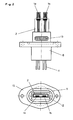
- Thin-film measuring elements 1a and 1b are arranged in the exhaust pipe 7.
- the thin-film measuring elements 1a and 1b are each parts of sheet resistors which are fastened in recesses of a ceramic carrier 2 and whose wires 3 are inserted in grooves of the ceramic carrier 2 designed as a plate.
- the wires 3 are remelted in the region of the grooves with a glass mass 4 so that they after cooling the glass melt Contracting so far that they are axially movable within the remaining glass envelope 4.
- the wires 3 of the sheet resistors are electrically connected to the thin-film measuring elements 1 a and 1 b and relieved of strain with a fixing drop 74.
- the wires 3 are sealed with a silicone seal 13 against the housing 8.
- the ceramic carrier 2 is sealed with a silicone gasket 12 against the plastic housing 8 to prevent the entry of media, e.g. B. exhaust gas or soot from the exhaust pipe in the plastic housing 8 to prevent and thus the formation of parallel resistors.
- the plastic housing 8 is an injection molded part made of PPS.
- a metallic shield 6 protects the injection molded part 8 from overheating by the exhaust gas. It remains between the shield 6 and the mounting flange of the exhaust pipe 7, an air gap to prevent contact of the exhaust pipe 7 with the shield 6.
- the injection molded part 8 is mounted on the flange 72 of the exhaust pipe 7 and sealed with an O-ring 9.
- connection lines 11 are sealed in the area of the plastic housing 8 with a seal 14 in order to prevent the entry of media, e.g. As salt water to prevent outside of the exhaust pipe and preclude the formation of parallel resistors by electrically conductive media.
- the seal 14 can be produced by pouring with sealant or by molding in an injection molding machine.
- Fig. 1 protrude from the sheet resistors 1a and 1b, the measuring elements through the slots 73a, 73b of the shield 6. Shielding and film resistors do not touch. Thus, the film resistors are neither mechanically loaded nor thermally coupled. The gap between the measuring element and the shield 6 is kept as low as possible, so that generated in this opening the exhaust gas flowing past the exhaust pipe as little turbulence and therefore the air insulation between the carrier 2 and the shield 6 as little as possible.
- the seals 13 and 14 prevent gas flows, so that the air between the support 2 and the shield 6 acts as a heat-insulating air cushion.
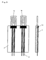
- FIG. 2 The side view of Fig. 2 illustrated without the shield 6 off Fig. 1 how the sheet resistors fastened on the support 2 are arranged with their wires 3 and the support 2 in the injection-molded housing 8 and are sealed with the seal 13.
- the seal 12 can be made by pouring be prepared with sealant. In this way, the carrier is fastened particularly stable in the housing. Furthermore, the seal prevents the entry of media between the carrier and the housing.
- the sheet resistors 1 a and 1 b according to Fig. 3 consist of a substrate and a thin-film conductor track arranged thereon, which are electrically connected to wires 3.
- the wires 3 are strain-relieved with a fixing drop 74.
- the sheet resistors 1 a and 1 b are arranged with their strain reliefs in recesses of the carrier 2 and the wires 3 of the sheet resistors placed in grooves of the carrier 2.
- a glass envelope 4 is generated, in which the wires are axially movable. For this purpose, both the recess and the grooves are filled with glass paste.
- the wires 3 contract, so that the wires 3 in the glass sheath 4 are axially movable. As a result, stresses due to the different expansion coefficients of glass sheath 4 and wires 3 are avoided.
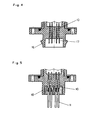
- connection area is formed with plug contacts 17 and a plastic border with latching hook 16 as a connector.
- An encapsulation of solid contact pins with plastic causes a strain relief of the connections and sealing the like.
- the parts to be inserted into one another are preferably sealed off from one another with a seal.
- the electrical connections 10 can also be embodied as a leadframe in order to widen the spacing of the connecting wires 3 to the spacing of the connection lines 11, without the connecting wires 3 having to be bent apart.
- connection lines 11 connection lines 11.
Landscapes
- Physics & Mathematics (AREA)
- Fluid Mechanics (AREA)
- General Physics & Mathematics (AREA)
- Measuring Volume Flow (AREA)
Abstract
Description
Die vorliegende Erfindung betrifft die Messung in Abgasströmen, insbesondere anemometrische Messungen, zur Abgasrückführung von Verbrennungskraftmaschinen.The present invention relates to the measurement in exhaust gas streams, in particular anemometric measurements, for the exhaust gas recirculation of internal combustion engines.
Einfache, insbesondere mit Spritzgussgehäusen hergestellte Messeinrichtungen mit geringeren Temperaturanforderungen sind nur für Temperaturen bis ungefähr 140°C geeignet. Dabei ist ein Freibrennen der Sensorelemente von Ablagerungen und Ruß nicht möglich, da die Dünnschicht-Messelemente gegebenenfalls aktiv auf 650°C aufgeheizt werden müssen, um sie von Ablagerungen, insbesondere Ruß, frei zu brennen. Im Messbetrieb werden die Sensoren mit Temperaturen oberhalb der Temperatur des Abgases betrieben. Dabei darf ein Kunststoffgehäuse des Flowsensors nicht überhitzt werden.Simple, especially with injection molded housings measuring devices with lower temperature requirements are suitable only for temperatures up to about 140 ° C. In this case, a burn-off of the sensor elements of deposits and soot is not possible because the thin-layer measuring elements may need to be actively heated to 650 ° C in order to burn them of deposits, especially soot, free. In measuring operation, the sensors are operated at temperatures above the temperature of the exhaust gas. In doing so, a plastic housing of the flow sensor must not be overheated.
Die Aufgabe der vorliegenden Erfindung besteht darin, einen Flowsensor mit einem Kunststoffgehäuse, insbesondere Spritzgussgehäuse, bereitzustellen, der zur Anwendung in einem Abgaskanal geeignet ist und dessen messaktiver Bereich frei gebrannt werden kann.The object of the present invention is to provide a flow sensor with a plastic housing, in particular injection-molded housing, which is suitable for use in an exhaust gas duct and whose measuring-active area can be burnt free.
Die Aufgabe wird durch die Merkmale der unabhängigen Ansprüche gelöst. Vorteilhafte Ausgestaltungen ergeben sich aus den abhängigen Ansprüchen.
Zur Lösung der Aufgabe werden die Schichtwiderstände auf einem keramischen Zwischenträger insbesondere einer Platte gehalten, über den die Temperatur bis zum Gehäuse abfallen kann.The object is solved by the features of the independent claims. Advantageous embodiments emerge from the dependent claims.
To achieve the object, the sheet resistors are held on a ceramic intermediate carrier, in particular a plate, via which the temperature can drop to the housing.
Das Kunststoffgehäuse wird weiterhin bezüglich der Abgastemperatur vor Überhitzung geschützt, indem es mitsamt dem Träger mit einer Metallkappe im Bereich des Abgases abgeschirmt ist, wobei die metallische Abschirmung bei der Befestigung der Messeinrichtung mit einem Luftspalt vom Abgasrohr beabstandet bleibt. Das Kunststoffgehäuse, insbesondere aus Spritzguss, wird bezüglich des Abgasrohres in oder am Ende eines Stutzens oder Schafts am Abgasrohr so weit zurückgezogen, dass es sich außerhalb des Abgasrohres befindet. Mit diesen Maßnahmen wird es ermöglicht, bis zu 300°C heiße Abgasströme mit einer ein Spritzgussgehäuse aufweisenden Messeinrichtung zu messen und Ablagerungen auf dem messaktiven Bereich freizubrennen.The plastic housing is further protected with respect to the exhaust gas temperature from overheating by being shielded together with the support with a metal cap in the region of the exhaust gas, wherein the metallic shield remains at the attachment of the measuring device with an air gap from the exhaust pipe. The plastic housing, in particular from injection molding, is so far withdrawn relative to the exhaust pipe in or at the end of a nozzle or stem on the exhaust pipe, that it is located outside of the exhaust pipe. These measures make it possible to measure hot exhaust gas flows of up to 300 ° C. with a measuring device having an injection-molded housing and to burn free deposits on the measurement-active area.
Erfindungsgemäß können die Dünnschicht-Messelemente gegebenenfalls aktiv auf 650° C zum Freibrennen von Ablagerungen hochgeheizt werden, ohne das Kunststoffgehäuse zu zerstören. Vorzugsweise werden Dünnfilm-Messelemente der Schichwiderstände auf einem Keramikträger mit Aussparungen positioniert. Vorzugsweise werden Drähte der Schichtwiderstände in Nuten der Keramikträger eingelegt und insbesondere dort mit Glas eingebettet.According to the invention, the thin-layer measuring elements can optionally be actively heated to 650 ° C for burnout of deposits without destroying the plastic housing. Preferably, thin film sensing elements of the resistors are positioned on a ceramic carrier with recesses. Preferably, wires of the sheet resistors are inserted into grooves of the ceramic carrier and in particular embedded there with glass.
Eine besonders einfache Kontaktierung zu Anschlussleitungen, insbesondere mittels Krimphülsen mit Schweißfläche, wird ermöglicht, wenn die Drähte des Schichtwiderstands an dem dem messaktiven Teil des Schichtwiderstands entgegen gesetzten Ende des Keramikträgers herausragen. Der Keramikträger weist vorzugsweise eine besonders geringe Wärmeleitfähigkeit auf, indem er beispielsweise aus Steatit besteht und somit nur wenig Wärme an das Kunststoffgehäuse weiterleitet. Wenn erfindungsgemäß durch die Metallkappe als Abschirmung intensiver Kontakt mit heißem Abgas vermieden wird, ist ein bis 230° C beständiger, spritzgießfähiger Kunststoff wie z. B. PPS als Gehäusewerkstoff einsetzbar. Damit werden erfindungsgemäß alle Vorteile der Spritzgusstechnik erschlossen. Vorzugsweise liegt deshalb das Kunststoffgehäuse außerhalb des Strömungsquerschnitts des Abgasrohres.A particularly simple contacting to connecting lines, in particular by means of Krimspülsen with welding surface, is made possible when the wires of the sheet resistance at the measuring active part of the sheet resistance opposite end of the ceramic support protrude. The ceramic carrier preferably has a particularly low thermal conductivity, for example, consists of steatite and thus passes little heat to the plastic housing. If according to the invention by the metal cap as a shield intensive contact with hot exhaust gas is avoided, is up to 230 ° C resistant, injection moldable plastic such. B. PPS used as a housing material. Thus, all advantages of the injection molding technology are developed according to the invention. Therefore, the plastic housing is preferably outside the flow cross section of the exhaust pipe.
Erfindungsgemäß kann der Keramikträger am Kunststoffgehäuse auch mit einem wärmebeständigen Elastomer, wie Silikonkautschuk oder Viton befestigt und abgedichtet werden. Vorzugsweise ist die Dichtung nicht kompressibel, wie beispielsweise Silikonkautschuk, mit dem Drücke bis 6 bar abgedichtet werden.According to the invention, the ceramic carrier can also be fastened and sealed to the plastic housing with a heat-resistant elastomer, such as silicone rubber or Viton. Preferably, the seal is not compressible, such as silicone rubber, are sealed with the pressures up to 6 bar.
Die Schichtwiderstände weisen auf einem Substrat, insbesondere Keramikplättchen befestigte Leiterbahnen auf die den messaktiven Widerstand bilden. Diese Leiterbahnen sind vorzugsweise strukturierte Dünnschichten, insbesondere aus Platin. Besonders bewährt haben sich für die vorliegende Erfindung Schichtwiderstände mit Anschlussdrähten, die mit einer Zugentlastung aus Glas die auf Kontaktfeldern befestigten Anschlussdrähte fixieren.The sheet resistors have printed conductors, which are attached to a substrate, in particular ceramic chips, and form the measuring active resistance. These interconnects are preferably structured thin layers, in particular of platinum. Have proven particularly for the Present invention sheet resistors with lead wires, which fix with a strain relief of glass attached to contact pads connecting wires.
Eine erfindungsgemäße Messeinrichtung, insbesondere anemometrische Messeinrichtung, zur Verwendung in einem Abgasrohr, insbesondere Abgasrückführrohr, bettet in einem Spritzgussgehäuse aus Kunststoff einen keramischer Träger, insbesondere eine Platte so ein, dass auf dem keramischen Träger an dem der Einbettung entgegen gesetzten Ende wenigstens ein Schichtwiderstand befestigt ist und von diesem aus Drähte zum eingebetteten Ende des keramischen Trägers führen. Die Drähte sind an elektrische Verbindungen angeschlossen, die durch den Spritzguss hindurchgeführt, innerhalb des Spritzgussteils abgedichtet und befestigt sind.A measuring device according to the invention, in particular anemometric measuring device, for use in an exhaust pipe, in particular exhaust gas recirculation pipe, embeds a ceramic carrier, in particular a plate, in an injection-molded plastic housing so that at least one sheet resistance is attached to the ceramic carrier at the end opposite to the embedding and from this lead wires to the embedded end of the ceramic carrier. The wires are connected to electrical connections that are passed through the injection molding, sealed within the injection molded part and fastened.
Vorzugsweise
- werden zur Abdichtung und Befestigung weitere Bauteile oder Materialien verwendet;
- ist der Schichtwiderstand mit Glasmasse auf dem keramischen Träger befestigt und abgedichtet;
- sind der Träger und das Spritzgussgehäuse mit einer Dichtung gegeneinander abgedichtet.
- sind die Drähte der Schichtwiderstände im eingebetteten Bereich des Trägers mittels Dichtmasse abgedeckt;
- weist das Spritzgussgehäuse einen Flansch auf;
- ist der Kontaktbereich der Drähte des Schichtwiderstands mit den elektrischen Verbindungen an dem dem Messwiderstand entgegen gesetzten Ende des Trägers mit einer Dichtungsmasse gegen den Träger und das Gehäuse abgedichtet;
- liegen die Drähte in Aussparungen des Trägers;
- weist der Schichtwiderstand einen an Drähte angeschlossen Messwiderstand auf, die im Bereich des Trägers mit einer Glasumhüllung umgeben sind.
- For sealing and fixing other components or materials are used;
- the sheet resistor is attached to the ceramic carrier and sealed with glass paste;
- the carrier and the injection-molded housing are sealed with a seal against each other.
- the wires of the film resistors are covered in the embedded region of the carrier by means of sealing compound;
- the injection-molded housing has a flange;
- the contact area of the wires of the film resistor with the electrical connections at the end of the carrier opposite the measuring resistor is sealed with a sealant against the carrier and the housing;
- the wires lie in recesses of the carrier;
- the sheet resistor has a measuring resistor connected to wires, which are surrounded in the region of the carrier with a glass cladding.
Zur Herstellung der Messeinrichtung werden die Drähte auf dem Träger, insbesondere der Platte mit einer Glasmasse eingebettet, die Glasmasse hierauf gebrannt und nach dem Brennen die Drähte durch Abkühlen von der Glasumhüllung gelöst, dass sie in der Glasumhüllung axial beweglich werden.To produce the measuring device, the wires are embedded on the carrier, in particular the plate with a glass mass, the glass mass fired thereon and after firing the wires solved by cooling of the glass envelope that they are axially movable in the glass envelope.
Die Messeinrichtung wird mit ihrem metallischen Gehäuse in ein Abgasrohr eingeschoben, ohne dass das metallische Gehäuse das Abgasrohr berührt. Das metallische Gehäuse wird auf das Kunststoffgehäuse gesteckt, welches direkt oder mit einer Dichtung an einem Flansch am Abgasrohr abgedichtet und befestigt wird.The measuring device is inserted with its metallic housing into an exhaust pipe without the metallic housing touching the exhaust pipe. The metallic housing will open the plastic housing inserted, which is sealed and fixed directly or with a seal to a flange on the exhaust pipe.
Die Befestigungsvorrichtung einer Messeinrichtung, insbesondere anemometrischen Messeinrichtung, in einem Abgasrohr, insbesondere Abgasrückführrohr, ist erfindungsgemäß so ausgeführt, dass die metallische Abschirmung vom Abgasrohr, insbesondere dessen Stutzen, für die Messeinrichtung mit einem Spalt beabstandet ist, so dass kein metallischer Kontakt zwischen dem Gehäuse und dem Abgasrohr in der oberen Hälfte des am Abgasrohr angesetzten abgasrohrseitigen Stutzens vorhanden ist und das Kunststoffgehäuse direkt oder mit einer Dichtung an einem Flansch oder am Ende des Stutzens des Abgasrohres anliegt.The fastening device of a measuring device, in particular anemometric measuring device, in an exhaust pipe, in particular exhaust gas recirculation pipe, according to the invention designed so that the metallic shield from the exhaust pipe, in particular the nozzle, for the measuring device is spaced with a gap, so that no metallic contact between the housing and the exhaust pipe is provided in the upper half of the exhaust pipe attached to the exhaust pipe side nozzle and the plastic housing rests directly or with a seal on a flange or at the end of the neck of the exhaust pipe.
Die Messeinrichtung weist einen Schichtwiderstand auf, der auf einem keramischen Träger befestigt ist und wobei der keramische Träger auf der dem funktionellen Messwiderstand des Schichtwiderstands entgegen gesetzten Seite von einem Kunststoffgehäuse (8) gehalten ist, welches mit einem Dichtungsmaterial gegen den Träger abgedichtet ist und an dem eine metallische Abschirmung befestigt ist, die den Träger und den Schichtwiderstand bis auf dessen Bereich des funktionellen Messwiderstands abschirmt.The measuring device has a sheet resistor which is mounted on a ceramic support and wherein the ceramic support is held on the opposite side of the functional resistance of the sheet resistance of a plastic housing (8) which is sealed with a sealing material against the support and on the a metallic shield is attached, which shields the support and the sheet resistance up to the region of the functional measuring resistor.
Im Folgenden wird die vorliegende Erfindung anhand von Beispielen mit Bezug auf die Zeichnungen verdeutlicht.
- Fig. 1
- zeigt einen Schnitt eines in einem Abgasrohr befestigten Anemometers;
- Fig. 2
- zeigt das Anemometer in Seitenansicht und Draufsicht;
- Fig. 3
- zeigt die Anordnung zweier Schichtwiderstände auf einem keramischen Träger in Draufsicht und Seitenansicht;
- Fig. 4
- zeigt Kontaktierungen der Drahtenden der Schichtwiderstände mit als Steckkontakt aus gebildeten Verbindungen;
- Fig. 5
- zeigt Kontaktierungen der Drahtenden der Schichtwiderstände über elektrische Verbindungen zu den Anschlussleitungen.
- Fig. 1
- shows a section of an anemometer mounted in an exhaust pipe;
- Fig. 2
- shows the anemometer in side view and plan view;
- Fig. 3
- shows the arrangement of two sheet resistors on a ceramic support in plan view and side view;
- Fig. 4
- shows contacts of the wire ends of the sheet resistors with connections formed as a plug-in contact;
- Fig. 5
- shows contacts of the wire ends of the sheet resistors via electrical connections to the connecting lines.
In der Anordnung nach
In
Die Dichtungen 13 und 14 unterbinden Gasströmungen, so dass die Luft zwischen dem Träger 2 und der Abschirmung 6 als wärmeisolierendes Luftkissen wirkt.The
Die Seitenansicht von
Die Schichtwiderstände 1 a und 1 b gemäß
Gemäß
Gemäß
Claims (12)
Applications Claiming Priority (1)
| Application Number | Priority Date | Filing Date | Title |
|---|---|---|---|
| DE102008037206.4A DE102008037206B4 (en) | 2008-08-11 | 2008-08-11 | 300 ° C-Flow Sensor |
Publications (2)
| Publication Number | Publication Date |
|---|---|
| EP2154493A2 true EP2154493A2 (en) | 2010-02-17 |
| EP2154493A3 EP2154493A3 (en) | 2014-07-09 |
Family
ID=40935672
Family Applications (1)
| Application Number | Title | Priority Date | Filing Date |
|---|---|---|---|
| EP09008739.6A Withdrawn EP2154493A3 (en) | 2008-08-11 | 2009-07-03 | 300°C flow sensor |
Country Status (4)
| Country | Link |
|---|---|
| US (1) | US7963162B2 (en) |
| EP (1) | EP2154493A3 (en) |
| JP (1) | JP5745755B2 (en) |
| DE (1) | DE102008037206B4 (en) |
Cited By (4)
| Publication number | Priority date | Publication date | Assignee | Title |
|---|---|---|---|---|
| EP2485018A1 (en) * | 2011-02-03 | 2012-08-08 | FESTO AG & Co. KG | Flow rate measuring device |
| DE102017203536A1 (en) | 2017-03-03 | 2018-09-06 | Ust Umweltsensortechnik Gmbh | Sensor element with wire guide |
| US10584987B2 (en) | 2015-09-30 | 2020-03-10 | Hitachi Automotive Systems, Ltd. | Physical quantity detection device |
| US10928232B2 (en) | 2014-11-06 | 2021-02-23 | Hitachi Automotive Systems, Ltd. | Thermal air flow meter |
Families Citing this family (11)
| Publication number | Priority date | Publication date | Assignee | Title |
|---|---|---|---|---|
| EP2140232A2 (en) * | 2007-04-26 | 2010-01-06 | Heraeus Sensor Technology Gmbh | Sheet resistor in an exhaust pipe |
| KR100994537B1 (en) * | 2010-06-28 | 2010-11-15 | 금양산업(주) | A thermal type flow sensing system for sensing amount of piston cooling oil of diesel engine for a ship |
| DE102011009754A1 (en) * | 2011-01-28 | 2012-08-02 | Heraeus Sensor Technology Gmbh | Flow sensors with current feed-through in the lid and sensor tip as an intermediate product |
| US9400197B2 (en) * | 2011-09-19 | 2016-07-26 | The Regents Of The University Of Michigan | Fluid flow sensor |
| DE102011056127B3 (en) * | 2011-12-07 | 2013-04-18 | Pierburg Gmbh | Device for determining gas mass flow in exhaust gas channel of internal combustion engine, has mass flow sensor whose sensing elements are arranged in honeycomb-shaped lattice portion |
| MX2014008439A (en) | 2012-01-12 | 2014-09-25 | Daniel Measurement & Control | Meter having banded shroud. |
| DE102013110487A1 (en) | 2012-12-14 | 2014-07-17 | Endress + Hauser Flowtec Ag | Thermal flowmeter |
| KR101777192B1 (en) * | 2016-02-15 | 2017-09-11 | 필즈엔지니어링 주식회사 | Flow meter |
| KR101778113B1 (en) | 2016-10-19 | 2017-09-13 | 필즈엔지니어링 주식회사 | Flare gas system for including vent analysis method |
| DE202016107242U1 (en) | 2016-12-21 | 2018-03-22 | Nordson Corp. | Sensor device for determining a mass flow of a liquid hot melt adhesive |
| US10274353B2 (en) * | 2017-03-22 | 2019-04-30 | A. O. Smith Corporation | Flow sensor with hot film anemometer |
Citations (2)
| Publication number | Priority date | Publication date | Assignee | Title |
|---|---|---|---|---|
| WO1981000494A1 (en) | 1979-07-27 | 1981-02-19 | Motorola Inc | Igfet decode circuit using series-coupled transistors |
| EP0990674A2 (en) | 1998-10-02 | 2000-04-05 | Takeda Chemical Industries, Ltd. | Method for decomposition and recovery of polyurethane resin |
Family Cites Families (42)
| Publication number | Priority date | Publication date | Assignee | Title |
|---|---|---|---|---|
| JPS63177023A (en) * | 1987-01-19 | 1988-07-21 | Nippon Soken Inc | Flow rate sensor |
| JP2605297B2 (en) * | 1987-09-04 | 1997-04-30 | 株式会社村田製作所 | Platinum temperature sensor and method of manufacturing the same |
| DE3804797A1 (en) * | 1988-02-16 | 1989-08-24 | Bosch Gmbh Robert | AIR MEASURING DEVICE |
| JP2564415B2 (en) * | 1990-04-18 | 1996-12-18 | 株式会社日立製作所 | Air flow detector |
| JP2839739B2 (en) * | 1991-03-13 | 1998-12-16 | 日本碍子株式会社 | Resistance element |
| JP2846518B2 (en) * | 1992-03-18 | 1999-01-13 | 株式会社日立製作所 | Air flow detector and engine control device using the same |
| JP2690655B2 (en) * | 1992-04-28 | 1997-12-10 | 株式会社日立製作所 | Thermal air flow meter |
| JP3228581B2 (en) * | 1992-12-24 | 2001-11-12 | 京セラ株式会社 | Ceramic heater |
| DE59507056D1 (en) | 1994-02-28 | 1999-11-18 | Heraeus Electro Nite Int | METHOD FOR ATTACHING A SENSOR ARRANGEMENT FOR HOT FILM GAUGE |
| DE4407209C2 (en) * | 1994-03-04 | 1996-10-17 | Bosch Gmbh Robert | Device for measuring the mass of a medium flowing in a line |
| JPH08219838A (en) * | 1995-02-15 | 1996-08-30 | Hitachi Ltd | Air flow measuring device |
| JP3331814B2 (en) * | 1995-05-18 | 2002-10-07 | 三菱電機株式会社 | Thermal flow detector |
| JP3438843B2 (en) * | 1995-06-14 | 2003-08-18 | 株式会社デンソー | Thermal flow meter |
| US6427668B1 (en) * | 1997-06-26 | 2002-08-06 | Hitachi, Ltd. | Thermal-type airflow meter, intake air system for an internal combustion engine, and control system for the same |
| US6337470B1 (en) * | 1997-10-06 | 2002-01-08 | Watlow Electric Manufacturing Company | Electrical components molded within a polymer composite |
| DE19813468C1 (en) * | 1998-03-26 | 1999-07-22 | Sensotherm Temperatursensorik | Sensor component e.g. a temperature sensor or an air or gas flow sensor |
| JP2000028411A (en) * | 1998-07-08 | 2000-01-28 | Mitsui Mining & Smelting Co Ltd | Flow-rate sensor and flow-rate detecting device |
| DE19901184C1 (en) * | 1999-01-14 | 2000-10-26 | Sensotherm Temperatursensorik | Platinum temperature sensor and method of manufacturing the same |
| JP3555017B2 (en) * | 1999-09-22 | 2004-08-18 | 三菱電機株式会社 | Thermal flow sensor |
| US7058532B1 (en) * | 1999-10-29 | 2006-06-06 | Mitsui Mining & Smelting Co., Ltd. | Flowmeter |
| DE19959854A1 (en) * | 1999-12-10 | 2001-06-13 | Heraeus Electro Nite Int | Method for exhaust gas recirculation in an air intake area of vehicle internal combustion engines and device |
| JP3825267B2 (en) * | 2000-02-23 | 2006-09-27 | 株式会社日立製作所 | Flow measurement device, physical detection device, and engine system |
| EP1128168A3 (en) * | 2000-02-23 | 2002-07-03 | Hitachi, Ltd. | Measurement apparatus for measuring physical quantity such as fluid flow |
| CN1272606C (en) * | 2000-07-27 | 2006-08-30 | 株式会社日立制作所 | Thermal type air flowmeter |
| US6588931B2 (en) * | 2000-12-07 | 2003-07-08 | Delphi Technologies, Inc. | Temperature sensor with flexible circuit substrate |
| US20030002994A1 (en) * | 2001-03-07 | 2003-01-02 | Johnson A. David | Thin film shape memory alloy actuated flow controller |
| JP2002372473A (en) * | 2001-04-12 | 2002-12-26 | Fuji Electric Co Ltd | Semiconductor-sensor housing container and method of manufacturing the same as well as semiconductor sensor device |
| DE10124964B4 (en) * | 2001-05-21 | 2004-02-05 | Forschungszentrum Karlsruhe Gmbh | Sensor for measuring flow velocities and method for its operation |
| DE10225602A1 (en) * | 2002-06-07 | 2004-01-08 | Heraeus Sensor-Nite Gmbh | Semiconductor component with integrated circuit, heat sink and temperature sensor |
| JP4310086B2 (en) * | 2002-08-01 | 2009-08-05 | 株式会社日立製作所 | Engine electronics |
| EP1431718A3 (en) | 2002-12-20 | 2007-11-14 | Heraeus Sensor Technology Gmbh | Flowmeter element using thin films and use |
| DE10314705B3 (en) * | 2003-03-31 | 2004-07-01 | Heraeus Sensor Technology Gmbh | Temperature sensor for flowing medium in pipe or flexible hose has ceramics substrate with thin film resistor held between ends of two metal conductor strips in plastics housing surrounding pipe |
| JP4609019B2 (en) * | 2004-09-24 | 2011-01-12 | 株式会社デンソー | Thermal flow sensor and manufacturing method thereof |
| JP2006317295A (en) * | 2005-05-13 | 2006-11-24 | Hitachi Ltd | Thermal type flowmeter |
| JP4830391B2 (en) * | 2005-07-29 | 2011-12-07 | 株式会社デンソー | Manufacturing method of sensor device and sensor device |
| EP1760437A1 (en) * | 2005-09-06 | 2007-03-07 | Sensirion AG | A method for manufacturing detector devices |
| EP1941244B1 (en) | 2005-10-24 | 2015-01-28 | Heraeus Sensor Technology Gmbh | Flow sensor element and its self-cleaning |
| DE102006030786A1 (en) * | 2006-06-30 | 2008-01-03 | Heraeus Sensor Technology Gmbh | Flow sensor element and its self-cleaning |
| DE102005061548B4 (en) * | 2005-12-22 | 2007-12-06 | Pierburg Gmbh | Method for operating an exhaust gas mass flow sensor |
| DE102006058425A1 (en) * | 2006-12-08 | 2008-06-19 | Heraeus Sensor Technology Gmbh | Motor exhaust gas return to the air intake has a hot film anemometer with separate heat and temperature measurement resistance layers |
| EP2140232A2 (en) | 2007-04-26 | 2010-01-06 | Heraeus Sensor Technology Gmbh | Sheet resistor in an exhaust pipe |
| DE202007014129U1 (en) * | 2007-10-09 | 2007-12-13 | Huba Control Ag | Sensor for urea solution to be injected into exhaust gases of internal combustion engines |
-
2008
- 2008-08-11 DE DE102008037206.4A patent/DE102008037206B4/en not_active Expired - Fee Related
-
2009
- 2009-07-03 EP EP09008739.6A patent/EP2154493A3/en not_active Withdrawn
- 2009-08-10 US US12/538,275 patent/US7963162B2/en not_active Expired - Fee Related
- 2009-08-11 JP JP2009186276A patent/JP5745755B2/en not_active Expired - Fee Related
Patent Citations (2)
| Publication number | Priority date | Publication date | Assignee | Title |
|---|---|---|---|---|
| WO1981000494A1 (en) | 1979-07-27 | 1981-02-19 | Motorola Inc | Igfet decode circuit using series-coupled transistors |
| EP0990674A2 (en) | 1998-10-02 | 2000-04-05 | Takeda Chemical Industries, Ltd. | Method for decomposition and recovery of polyurethane resin |
Cited By (5)
| Publication number | Priority date | Publication date | Assignee | Title |
|---|---|---|---|---|
| EP2485018A1 (en) * | 2011-02-03 | 2012-08-08 | FESTO AG & Co. KG | Flow rate measuring device |
| US10928232B2 (en) | 2014-11-06 | 2021-02-23 | Hitachi Automotive Systems, Ltd. | Thermal air flow meter |
| US10584987B2 (en) | 2015-09-30 | 2020-03-10 | Hitachi Automotive Systems, Ltd. | Physical quantity detection device |
| DE102017203536A1 (en) | 2017-03-03 | 2018-09-06 | Ust Umweltsensortechnik Gmbh | Sensor element with wire guide |
| DE102017203536B4 (en) * | 2017-03-03 | 2021-04-01 | Ust Umweltsensortechnik Gmbh | Sensor element with wire guide |
Also Published As
| Publication number | Publication date |
|---|---|
| US7963162B2 (en) | 2011-06-21 |
| JP5745755B2 (en) | 2015-07-08 |
| JP2010044071A (en) | 2010-02-25 |
| EP2154493A3 (en) | 2014-07-09 |
| DE102008037206A1 (en) | 2010-03-04 |
| DE102008037206B4 (en) | 2014-07-03 |
| US20100031742A1 (en) | 2010-02-11 |
Similar Documents
| Publication | Publication Date | Title |
|---|---|---|
| DE102008037206B4 (en) | 300 ° C-Flow Sensor | |
| EP1941244B1 (en) | Flow sensor element and its self-cleaning | |
| DE112013001060B4 (en) | Thermal air volume measuring device | |
| EP2282179B1 (en) | Method for manufacturing a temperature sensor | |
| EP2492649A1 (en) | Flow sensor with feed through in the cover of its enclosure and sensor tip as intermediate product | |
| DE102007057221B4 (en) | Flow rate measuring device | |
| DE102006034248B3 (en) | Temperature sensor for resistance thermometer, has electrical measuring resistor containing protective pipe close to top, and electrically isolated filler filling space between pipe on one side and resistor and its supplies on another side | |
| EP2140232A2 (en) | Sheet resistor in an exhaust pipe | |
| WO2008000494A2 (en) | Sheet resistor in an exhaust pipe | |
| DE102008060033A1 (en) | Temperature sensor for turbocharger | |
| DE102007011535B4 (en) | High temperature sensor | |
| EP2850308B1 (en) | Oxygen sensor and internal combustion engine comprising such a sensor | |
| EP2909593B1 (en) | Temperature sensor and thermal flow rate measurement device | |
| DE112013002976T5 (en) | Thermal flow meter | |
| DE112013002992T5 (en) | Thermal flow meter | |
| DE202013103402U1 (en) | Temperature sensor and thermal flow meter | |
| DE112013002939T5 (en) | Thermal flow meter | |
| DE69819850T2 (en) | ELECTRICAL DEVICE WITH ATMOSPHERIC INSULATION | |
| EP2732254A2 (en) | High-temperature measuring sensor assembly | |
| DE102009011750B3 (en) | Temperature sensor for a cylinder head of an engine | |
| DE102022111698A1 (en) | Temperature sensor and method for producing a temperature sensor | |
| DE102010048312B3 (en) | Method for manufacturing high temperature sensor arrangement for, e.g. exhaust gas passage of motor vehicle combustion engine, involves providing fixed mechanical coupling between mold component, sensor element and electrical lead | |
| DE102013204911B4 (en) | sensor device | |
| Muziol et al. | 300 C Flow Sensor | |
| DE10031666A1 (en) | Heater element for escaping gas from crankcase of internal combustion engine has shoulder for securing clamp and has ceramic valve seat with profiled section |
Legal Events
| Date | Code | Title | Description |
|---|---|---|---|
| PUAI | Public reference made under article 153(3) epc to a published international application that has entered the european phase |
Free format text: ORIGINAL CODE: 0009012 |
|
| 17P | Request for examination filed |
Effective date: 20090715 |
|
| AK | Designated contracting states |
Kind code of ref document: A2 Designated state(s): AT BE BG CH CY CZ DE DK EE ES FI FR GB GR HR HU IE IS IT LI LT LU LV MC MK MT NL NO PL PT RO SE SI SK SM TR |
|
| AX | Request for extension of the european patent |
Extension state: AL BA RS |
|
| PUAL | Search report despatched |
Free format text: ORIGINAL CODE: 0009013 |
|
| AK | Designated contracting states |
Kind code of ref document: A3 Designated state(s): AT BE BG CH CY CZ DE DK EE ES FI FR GB GR HR HU IE IS IT LI LT LU LV MC MK MT NL NO PL PT RO SE SI SK SM TR |
|
| AX | Request for extension of the european patent |
Extension state: AL BA RS |
|
| RIC1 | Information provided on ipc code assigned before grant |
Ipc: G01F 1/692 20060101ALI20140602BHEP Ipc: F02M 25/07 20060101ALI20140602BHEP Ipc: G01F 1/684 20060101AFI20140602BHEP |
|
| 17Q | First examination report despatched |
Effective date: 20170428 |
|
| STAA | Information on the status of an ep patent application or granted ep patent |
Free format text: STATUS: THE APPLICATION IS DEEMED TO BE WITHDRAWN |
|
| 18D | Application deemed to be withdrawn |
Effective date: 20180526 |