EP2154450A2 - Refrigerating device - Google Patents
Refrigerating device Download PDFInfo
- Publication number
- EP2154450A2 EP2154450A2 EP20090162388 EP09162388A EP2154450A2 EP 2154450 A2 EP2154450 A2 EP 2154450A2 EP 20090162388 EP20090162388 EP 20090162388 EP 09162388 A EP09162388 A EP 09162388A EP 2154450 A2 EP2154450 A2 EP 2154450A2
- Authority
- EP
- European Patent Office
- Prior art keywords
- oil
- motor
- compressor
- refrigerating device
- flow passage
- Prior art date
- Legal status (The legal status is an assumption and is not a legal conclusion. Google has not performed a legal analysis and makes no representation as to the accuracy of the status listed.)
- Granted
Links
- 239000003507 refrigerant Substances 0.000 claims abstract description 50
- 238000004804 winding Methods 0.000 claims abstract description 34
- 229920005989 resin Polymers 0.000 claims description 22
- 239000011347 resin Substances 0.000 claims description 22
- 125000001153 fluoro group Chemical group F* 0.000 claims description 21
- XAGFODPZIPBFFR-UHFFFAOYSA-N aluminium Chemical compound [Al] XAGFODPZIPBFFR-UHFFFAOYSA-N 0.000 claims description 12
- 229910052782 aluminium Inorganic materials 0.000 claims description 12
- 238000001816 cooling Methods 0.000 claims 1
- 230000007423 decrease Effects 0.000 abstract description 16
- 238000009413 insulation Methods 0.000 abstract description 14
- QGZKDVFQNNGYKY-UHFFFAOYSA-N Ammonia Chemical compound N QGZKDVFQNNGYKY-UHFFFAOYSA-N 0.000 description 79
- 229910021529 ammonia Inorganic materials 0.000 description 33
- 238000007906 compression Methods 0.000 description 6
- 239000000314 lubricant Substances 0.000 description 6
- 230000006835 compression Effects 0.000 description 5
- 239000007788 liquid Substances 0.000 description 3
- 239000000126 substance Substances 0.000 description 3
- BFKJFAAPBSQJPD-UHFFFAOYSA-N tetrafluoroethene Chemical group FC(F)=C(F)F BFKJFAAPBSQJPD-UHFFFAOYSA-N 0.000 description 3
- XLYOFNOQVPJJNP-UHFFFAOYSA-N water Substances O XLYOFNOQVPJJNP-UHFFFAOYSA-N 0.000 description 3
- RTZKZFJDLAIYFH-UHFFFAOYSA-N Diethyl ether Chemical compound CCOCC RTZKZFJDLAIYFH-UHFFFAOYSA-N 0.000 description 2
- 239000002033 PVDF binder Substances 0.000 description 2
- 229920001577 copolymer Polymers 0.000 description 2
- 230000005484 gravity Effects 0.000 description 2
- 238000009434 installation Methods 0.000 description 2
- 229920002493 poly(chlorotrifluoroethylene) Polymers 0.000 description 2
- 239000005023 polychlorotrifluoroethylene (PCTFE) polymer Substances 0.000 description 2
- -1 polytetrafluoroethylene Polymers 0.000 description 2
- 229920001343 polytetrafluoroethylene Polymers 0.000 description 2
- 239000004810 polytetrafluoroethylene Substances 0.000 description 2
- 229920002981 polyvinylidene fluoride Polymers 0.000 description 2
- QGZKDVFQNNGYKY-UHFFFAOYSA-O Ammonium Chemical compound [NH4+] QGZKDVFQNNGYKY-UHFFFAOYSA-O 0.000 description 1
- 229920001038 ethylene copolymer Polymers 0.000 description 1
- 229920000840 ethylene tetrafluoroethylene copolymer Polymers 0.000 description 1
- XLYOFNOQVPJJNP-UHFFFAOYSA-M hydroxide Chemical compound [OH-] XLYOFNOQVPJJNP-UHFFFAOYSA-M 0.000 description 1
- 238000005259 measurement Methods 0.000 description 1
- 238000000034 method Methods 0.000 description 1
- 230000002093 peripheral effect Effects 0.000 description 1
- 230000035699 permeability Effects 0.000 description 1
- 230000002265 prevention Effects 0.000 description 1
- 239000007921 spray Substances 0.000 description 1
- 238000011144 upstream manufacturing Methods 0.000 description 1
Images



Classifications
-
- F—MECHANICAL ENGINEERING; LIGHTING; HEATING; WEAPONS; BLASTING
- F25—REFRIGERATION OR COOLING; COMBINED HEATING AND REFRIGERATION SYSTEMS; HEAT PUMP SYSTEMS; MANUFACTURE OR STORAGE OF ICE; LIQUEFACTION SOLIDIFICATION OF GASES
- F25B—REFRIGERATION MACHINES, PLANTS OR SYSTEMS; COMBINED HEATING AND REFRIGERATION SYSTEMS; HEAT PUMP SYSTEMS
- F25B45/00—Arrangements for charging or discharging refrigerant
-
- F—MECHANICAL ENGINEERING; LIGHTING; HEATING; WEAPONS; BLASTING
- F25—REFRIGERATION OR COOLING; COMBINED HEATING AND REFRIGERATION SYSTEMS; HEAT PUMP SYSTEMS; MANUFACTURE OR STORAGE OF ICE; LIQUEFACTION SOLIDIFICATION OF GASES
- F25B—REFRIGERATION MACHINES, PLANTS OR SYSTEMS; COMBINED HEATING AND REFRIGERATION SYSTEMS; HEAT PUMP SYSTEMS
- F25B31/00—Compressor arrangements
- F25B31/002—Lubrication
- F25B31/004—Lubrication oil recirculating arrangements
-
- F—MECHANICAL ENGINEERING; LIGHTING; HEATING; WEAPONS; BLASTING
- F04—POSITIVE - DISPLACEMENT MACHINES FOR LIQUIDS; PUMPS FOR LIQUIDS OR ELASTIC FLUIDS
- F04C—ROTARY-PISTON, OR OSCILLATING-PISTON, POSITIVE-DISPLACEMENT MACHINES FOR LIQUIDS; ROTARY-PISTON, OR OSCILLATING-PISTON, POSITIVE-DISPLACEMENT PUMPS
- F04C29/00—Component parts, details or accessories of pumps or pumping installations, not provided for in groups F04C18/00 - F04C28/00
-
- F—MECHANICAL ENGINEERING; LIGHTING; HEATING; WEAPONS; BLASTING
- F25—REFRIGERATION OR COOLING; COMBINED HEATING AND REFRIGERATION SYSTEMS; HEAT PUMP SYSTEMS; MANUFACTURE OR STORAGE OF ICE; LIQUEFACTION SOLIDIFICATION OF GASES
- F25B—REFRIGERATION MACHINES, PLANTS OR SYSTEMS; COMBINED HEATING AND REFRIGERATION SYSTEMS; HEAT PUMP SYSTEMS
- F25B31/00—Compressor arrangements
- F25B31/002—Lubrication
-
- F—MECHANICAL ENGINEERING; LIGHTING; HEATING; WEAPONS; BLASTING
- F25—REFRIGERATION OR COOLING; COMBINED HEATING AND REFRIGERATION SYSTEMS; HEAT PUMP SYSTEMS; MANUFACTURE OR STORAGE OF ICE; LIQUEFACTION SOLIDIFICATION OF GASES
- F25B—REFRIGERATION MACHINES, PLANTS OR SYSTEMS; COMBINED HEATING AND REFRIGERATION SYSTEMS; HEAT PUMP SYSTEMS
- F25B43/00—Arrangements for separating or purifying gases or liquids; Arrangements for vaporising the residuum of liquid refrigerant, e.g. by heat
-
- F—MECHANICAL ENGINEERING; LIGHTING; HEATING; WEAPONS; BLASTING
- F25—REFRIGERATION OR COOLING; COMBINED HEATING AND REFRIGERATION SYSTEMS; HEAT PUMP SYSTEMS; MANUFACTURE OR STORAGE OF ICE; LIQUEFACTION SOLIDIFICATION OF GASES
- F25B—REFRIGERATION MACHINES, PLANTS OR SYSTEMS; COMBINED HEATING AND REFRIGERATION SYSTEMS; HEAT PUMP SYSTEMS
- F25B49/00—Arrangement or mounting of control or safety devices
- F25B49/02—Arrangement or mounting of control or safety devices for compression type machines, plants or systems
-
- H—ELECTRICITY
- H02—GENERATION; CONVERSION OR DISTRIBUTION OF ELECTRIC POWER
- H02K—DYNAMO-ELECTRIC MACHINES
- H02K3/00—Details of windings
- H02K3/30—Windings characterised by the insulating material
-
- F—MECHANICAL ENGINEERING; LIGHTING; HEATING; WEAPONS; BLASTING
- F25—REFRIGERATION OR COOLING; COMBINED HEATING AND REFRIGERATION SYSTEMS; HEAT PUMP SYSTEMS; MANUFACTURE OR STORAGE OF ICE; LIQUEFACTION SOLIDIFICATION OF GASES
- F25B—REFRIGERATION MACHINES, PLANTS OR SYSTEMS; COMBINED HEATING AND REFRIGERATION SYSTEMS; HEAT PUMP SYSTEMS
- F25B1/00—Compression machines, plants or systems with non-reversible cycle
- F25B1/04—Compression machines, plants or systems with non-reversible cycle with compressor of rotary type
- F25B1/047—Compression machines, plants or systems with non-reversible cycle with compressor of rotary type of screw type
Definitions
- the present invention relates to a refrigerating device, and more particularly to a refrigerating device for an ammonia refrigerant employing ammonia as a refrigerant.
- the lubricant stored at a bottom of the device is pumped up through a rotor shaft of the motor arranged in the vertical direction, and is sprayed by means of gravity from a center hole of the rotor shaft provided at the uppermost portion of the motor to the windings of the stator arranged below.
- the invention is intended to bring the windings of the stator in a state submerged by the lubricant, thereby shutting off a direct contact to ammonia, there is a limitation to deliver the lubricant over the entire windings.
- the structure for storing the lubricant becomes complex, resulting in a large increase in cost. Further, the structure essentially requires an arrangement for vertically standing the motor, resulting in a demerit of restriction on the environment for installation.
- fluoro resin is especially inactive to most of chemicals, and is considered to have an excellent chemical resistance.
- the fluoro resin providing such excellent chemical resistance is used along with the ammonia gas, and the appearance of the fluoro resin is not damaged, an insulation capability of the motor decreases with the elapse of time.
- the present invention is devised based on this new knowledge, and has an object to provide a refrigerating device which does not present a decrease in the insulation capability of a motor after a long period has elapsed.
- a refrigerating device includes a compressor that is driven by a motor; a refrigerant circulation flow passage that comprises an oil separator/collector, a condenser, an expansion valve, and an evaporator; an oil flow passage that conducts oil in the oil separator/collector to a bearing and a shaft seal unit of the compressor; a motor casing that stores the motor, an internal pressure of the motor casing is lower than a pressure in an oil sump in the refrigerant circulation flow passage on a discharge side of the compressor; an oil supply opening that is provided for the motor casing; and an oil supply line that is constructed to supply oil from the oil sump to the oil supply opening.
- the refrigerating device preferably includes a control valve that is provided for the oil supply line, and control means that controls the control valve so as to adjust a quantity of oil supplied to the oil supply opening.
- control valve that is provided for the oil supply line
- control means that controls the control valve so as to adjust a quantity of oil supplied to the oil supply opening.
- the refrigerating device is preferably configured such that the oil before cooled by an oil cooler provided for the oil flow passage is supplied to the oil supply opening of the motor from the oil flow passage via the oil supply line.
- an oil cooler provided for the oil flow passage
- By directly supplying the oil which is not cooled from the separator/collector to the oil supply opening of the motor it is possible to main the coil temperature of the motor without a decrease, thereby preventing the ammonia gas from being liquefied on the coils.
- the refrigerating device is preferably configured such that the oil sump is an oil sump portion of the oil separator/collector, or in multi-stage screw rotors, the oil sump is an oil sump in an intermediate-stage portion between one pair of screw rotors and the other pair of screw rotors adjacent to the one pair of screw rotors out of the multi-stage screw rotors.
- the oil sump is an oil sump portion of the oil separator/collector, or in multi-stage screw rotors adjacent to the one pair of screw rotors out of the multi-stage screw rotors.
- the refrigerating device is preferably configured such that a suction opening of the compressor is provided on an opposite side of the motor casing with respect to the discharge side of the compressor. This configuration more surely allows the supplied oil to be distributed inside the motor and pass across the motor, by means of the ammonia refrigerant gas sucked from the suction opening of the compressor.
- the refrigerating device is preferably configured such that an aluminum wire of the winding of the motor is loosely covered by a fluoro resin.
- the loose coverage means that the aluminum wire is covered by the fluoro resin without a close contact.
- FIG. 1 shows a two-stage screw refrigerating device for ammonia refrigerant 1A according to a first embodiment of the present invention.
- the two-stage screw refrigerating device 1A includes a refrigerant circulation flow passage 2 which contains a two-stage oil-cooled screw compressor 11 (hereinafter, simply referred to as screw compressor 11), an oil separator/collector 12, a condenser 13, an expansion valve 14, and an evaporator 15, an oil flow passage 3 which conducts an oil in the oil separator/collector 12, namely the oil in an oil sump portion 16 at a bottom portion of the oil separator/collector 12 to after-mentioned oil supply locations in the screw compressor 11, and an oil supply line 20 which branches from the oil flow passage 3, and supply oil via a control valve 17 to an oil supply opening 19 of an after-mentioned motor 18.
- a control device (control means) 21 which controls the control valve 17 is provided. Between the oil separator/collector 12 and the oil supply locations of the oil flow passage 3, a cooler
- the screw compressor 11 includes a pair of first-stage male/female screw rotors 26 meshing with each other, and a pair of second-stage male/female screw rotors 27 meshing with each other in a compressor casing 25. And a suction opening 23 is formed on one side of the compressor casing 25, and a discharge opening 24 is formed on the other side thereof.
- an intermediate-stage portion 28 between the first-stage screw rotors 26 and the second-stage screw rotors 27 an intermediate oil sump 29 for storing the oil is formed.
- a filter 30 is provided on an upstream side of the suction opening 23, a filter 30 is provided.
- a discharge portion 31 is provided on a side of the intermediate-stage portion 28 of the first-stage screw rotors 26 .
- a suction portion 32 is provided on a side of the intermediate-stage portion 28 of the second-stage screw rotors 27, a suction portion 32 is provided.
- the first-stage screw rotors 26 and the second-stage screw rotors 27 are rotationally supported by bearing/shaft seal units 33, 34, and 35, and a male rotor 36 of the first-stage screw rotors 26 and a male rotor 37 of the second-stage screw rotors 27 share a rotor shaft 38 for coaxially rotating.
- a motor casing 39 of the motor 18, which is a driving unit of the screw compressor 11 forms, along with a compressor casing 25 which is integrally joined to the motor casing 39, a semi-hermetic structure.
- a motor chamber 42 is provided, and the motor chamber 42 stores a rotor 40 which shares the shaft with the male rotor 36 of the first-stage screw rotors 26, and a stator 41 enclosing the rotor 40.
- the shaft of this male rotor 36 also constitutes an output shaft of the motor 18.
- the motor 18 drives the first-stage screw rotors 26 and the second-stage screw rotors 27 to rotate via this male rotor 36 and the male rotor 37 of the second-stage screw rotors 27.
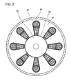
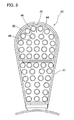
- a large number of windings 43 are wound inside insulation casings 47 of the stator 41 of the motor 18 shown in FIGS. 2 and 3 . There are spaces 45 between the windings 44 and 44. Aluminum wires 49 of the windings 44 of the stator 41 of the motor 18 are loosely covered by a fluoro resin 50.
- the fluoro resin herein includes polytetrafluoroethylene (PTFE), tetrafluoroethylene/perfluoro alkyl vinyl ether copolymer (PFA), tetrafluoroethylene/hexafluoropropylene copolymer (FEP), tetrafluoroethylene/ethylene copolymer (ETFE), polyvinylidene fluoride (PVDF), and polychlorotrifluoroethylene (PCTFE).
- PTFE polytetrafluoroethylene
- PFA tetrafluoroethylene/perfluoro alkyl vinyl ether copolymer
- FEP tetrafluoroethylene/hexafluoropropylene copolymer
- ETFE tetrafluoroethylene/ethylene copolymer
- PVDF polyvinylidene fluoride
- PCTFE polychlorotrifluoroethylene
- FEP is used.
- the oil supply opening 19 is provided for an opposite side surface of the
- the oil supply opening 19 is not limited to the one provided at the above-described location, and a part of the oil supply line 20 may be configured as an oil supply line 20a shown in a dashed-dotted line, and the oil supply opening 19 may be provided at a end portion of the oil supply line 20a, namely on an outer peripheral surface of the opposite side of the motor casing 39 of the motor 18 with respect to the first-stage screw rotors 26.
- ammonia refrigerant gas sucked from the suction opening 23 of the screw compressor 11 is compressed while the oil from the oil flow passage 3 is being fed, and is discharged along with the oil from the discharge portion 31 to the intermediate-stage portion 28. Further, the ammonia refrigerant gas accompanying the oil is sucked from the suction portion 32 into the second-stage screw rotors 27, is compressed while the oil from the oil flow passage 3 is being fed, and is discharged accompanying the oil from the discharge opening 24 to the oil separator/collector 12.
- the oil supplied to the bearing/shaft seal units 33, 34, and 35 is also returned to the oil separator/collector 12, the oil separator/collector 12 separates the ammonia refrigerant gas and the oil from each other, the oil is temporarily stored in the oil sump portion 16, and the ammonia refrigerant gas from which the oil has been separated is fed out to a portion of the refrigerant circulation flow passage 2 extending from a top portion of the oil separator/collector 12.
- Heat is taken from the ammonia refrigerant gas exiting from the oil separator/collector 12 by a low-temperature heat source such as water in the condenser 13, the ammonia refrigerant gas is condensed into a refrigerant liquid, the refrigerant liquid flows from the condenser 13 to the expansion valve 14, is partially vaporized into gas through the expansion valve 14 to lower the temperature, the refrigerant gas takes heat from a high-temperature heat source in the evaporator 15, is completely vaporized into gas, passes through the filter 30, and returns to the suction opening 23 of the two-stage screw refrigerating device 1A.
- a low-temperature heat source such as water in the condenser 13
- the refrigerant liquid flows from the condenser 13 to the expansion valve 14
- the refrigerant gas takes heat from a high-temperature heat source in the evaporator 15
- is completely vaporized into gas passes through the filter 30, and returns to the suction opening 23 of the two-stage
- the oil in the oil sump portion 16 is at high temperature by the compression of the screw compressor 11, the oil is cooled by the cooler 22 of the oil flow passage 3, is fed to the bearing/shaft seal units 33, 34, and 35, is conducted to each of the gas compression spaces formed by the first-stage screw rotors 26 and the second-stage screw rotors 27, and is collected by the oil separator/collector 12 for repeated use for circulating.
- the gas compression spaces are spaces in the gas compression process, the gas compression spaces do not communicate with the suction opening 23, the discharge opening 21, the suction portion 32, and the discharge portion 24.
- the oil in the oil supply line 20 branching from the oil flow passage 3 is supplied via the control valve 17 to the oil supply opening 19 of the motor 18.
- the supplied oil is scattered in the motor chamber 42, and tends to be conducted to the spaces 45 between the windings 44 of the stator 41 of the motor 18.
- the oil after passing through the motor chamber 42 passes through the bearing/shaft seal unit 33, and is finally fed to the oil separator/collector 12.
- the oil used by the present embodiment is AG46 from Nippon Oil Corporation.
- the oil since the oil is supplied from the oil supply line 20 at a high pressure to the oil supply opening 19 of the motor 18, the oil is sprayed and is distributed across the entire surface of the windings 44, and closes the minute holes of the fluoro resin, the oil of the refrigerating device with a high insulation property interposes between the windings 44. As a result, after a long period elapses, the insulation capability of the motor 18 will not decrease.
- the oil sumps in the refrigerant circulation flow passage 2 on the discharge side of the screw compressor 11 are the oil sump portion 16 of the oil separator/collector 12 and the oil sump 29 of the intermediate-stage portion 28 between the first-stage screw rotors 26 and the second-stage screw rotors 27, and the former oil sump is employed as a source of the oil supply to the oil supply opening 19 of the motor. Then, since the oil sump portion 16 of the oil separator/collector 12 is employed as the source of the oil supply, it is not necessary to supply the oil from the outside.
- FIG. 4 shows a result of a measurement of an insulation resistance of the motor 18 after a predetermined long period, carried out by the present inventor in order to clarify a difference between before and after the oil is supplied between the windings 44 and 44 of the motor 18. It is appreciated that the insulation resistance of the motor 18 largely increases after the supply of the oil in comparison to before the supply of the oil. Based on this result, it is considered that the oil needs to be interposed between the windings 44 and 44 of the motor 18.
- the oil supply from the oil flow passage 3 via the oil supply line 20 to the oil supply opening 19 is carried out by the control of the control device 21 for opening/closing the control valve 17.
- the control device 21 controls the control valve 17 to correctly open and close, and adjusts an opening of the control valve 17 or adjusts an open period and a closed period of the control valve 17 per unit time period to control the quantity of the oil supply.
- the pressure on the primary side of the control valve 17 is maintained to a pressure approximately the same as a discharge pressure of the screw compressor 11, and is higher than that in the motor chamber 42 inside the motor casing 39, which is approximately the same as a suction pressure, and, thus, when the control valve 17 is opened, the oil is supplied via the oil supply opening 19 into the motor chamber 42.
- the difference in pressure is as follows.
- the discharge pressure Pd at the discharge opening 24 is 1.6 MPa
- the suction pressure Ps at the suction opening 23 is 0.05 MPa
- the difference in pressure ⁇ P is 1.55 MPa. It should be noted that the pressure inside the motor chamber 42 is approximately equal to the suction pressure at the suction opening 23.
- the control through the control valve 17 for supply of the oil to the motor chamber 42 allows intermittent supply of the oil in the required quantity while the timing is freely selected.
- the supply of the oil to the motor chamber 42 to the minimum necessary allows the restraint of increase of a friction resistance caused by an excessive supply of the oil and the prevention of the decrease of performance of the motor 18.
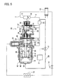
- FIG. 5 shows a two-stage screw refrigerating device for ammonia refrigerant 1B according to a second embodiment of the present invention.
- the branch location from the oil flow passage 3 to the oil supply line 20 is between the oil separator/collector 12 and the cooler 22, which is different from the first embodiment.
- the oil supplied by the oil supply line 20 is not cooled by the cooler 22.
- the supply of the oil does not cause the decrease of the temperature of the coils (windings 44) of the motor 18, thereby preventing the ammonia gas from being liquefied on the coils.
- FIG. 6 shows a two-stage screw refrigerating device for ammonia refrigerant 1C according to a third embodiment of the present invention. Same components in the present embodiment are also denoted by same numerals as of the first embodiment and will not be further explained. According to the present embodiment, a point different from the first embodiment is that the source of the oil supply is not the oil separator/collector 12, but the intermediate oil sump 29 in the intermediate-stage portion 28, and the oil supply line 20 does not communicate with the oil flow passage 3.
- the pressures at the respective locations according to the present embodiment are as follows.
- the suction pressure Ps at the suction opening 23 is 0.05 MPa
- the discharge pressure Pd at the discharge opening 24 is 1.6 MPa
- the intermediate pressure Pm at the intermediate-stage portion 28 is 0.4 MPa.
- the quantity of a gas dissolved in a liquid in a certain quantity is proportional to the pressure (partial pressure) of the gas.
- the temperatures of the ammonia refrigerant gas gradually increases, as the ammonia refrigerant gas flows from the suction opening 23 through the intermediate-stage portion 28 to the discharge opening 24. Therefore, it is considered that the quantity of the ammonia refrigerant gas dissolved in the oil at the respective locations is approximately proportional to the pressure at the respective locations (since the temperature of the respective locations are not constant, it is not considered that the dissolved quantity is completely "proportional" to the pressure).
- the quantity of the ammonia refrigerant gas dissolved in the oil at the respective locations increases as the ammonia refrigerant gas flows from the suction opening 23, via the intermediate-stage portion 28, to the discharge opening 24.
- the solubility of the ammonia refrigerant gas to the oil is smaller in the oil sump 29 in the intermediate-stage portion 28 than in the oil sump portion 16 of the oil separator/collector 12, which is under pressure approximately equal to that at the discharge opening 24.
- the present embodiment by supplying the oil in the oil supply line 20 from the intermediate oil sump 29 of the intermediate-stage portion 28, it is possible to reduce the quantity of the ammonia refrigerant gas dissolved in the oil and supplied to the motor chamber 42, and, as a result, it is possible to reduce the quantity of the flash gas when the oil is supplied to the motor chamber 42.
- the quantity of the refrigerant passing through the evaporator 15 increases in comparison to the first and second embodiments, resulting in an increase in performance as the refrigerating device.
- the supply source of the oil is the intermediate oil sump 29 in the intermediate-stage portion 28 between the first-stage screw rotors 26 and the second-stage screw rotors 27, it is not necessary to supply the oil from the outside.
- the point that the oil is positively supplied into the windings 43 of the motor chamber 42 by means of the difference in pressure is the same as the first and second embodiments.
- the present invention is not limited to these, a single-stage screw compressor or a multi-stage screw compressor other than the two-stage screw compressor 11 may be used.
- a multi-stage screw compressor other than the two-stage screw compressor 11 shown in FIG. 6 may be used.
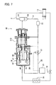
- a screw refrigerating device for ammonia refrigerant 1D according to a fourth embodiment shown in FIG.
- the suction opening 48 of a compressor 11D may be provided on the opposite side of the motor casing 39 of the motor 18 with respect to the discharge side of the compressor 11D, thereby the ammonia refrigerant gas may pass through the motor chamber 42.
- This configuration more surely allows the supplied oil to be distributed inside the motor 18 and pass across the motor 18, by means of the ammonia refrigerant gas sucked from the suction opening 48 of the compressor 11D.
- a single stage screw compressor 11D is used as an example, the present invention is not limited to this, a multi-stage screw compressor may be used.
- the screw compressors 11 and 11D are used as examples, the present invention is not limited to these, other compressors such as a scroll compressor may be used.
- a refrigerating device comprising: a compressor that is driven by a motor; a refrigerant circulation flow passage that includes an oil separator/collector, a condenser, an expansion valve, and an evaporator; and an oil flow passage that conducts oil in the oil separator/collector to a bearing of the compressor, an oil supply opening is provided for a motor casing that stores the motor, an oil supply line for supplying oil from an oil sump of the refrigerant circulation flow passage on the discharge side of the compressor to the oil supply opening is provided, oil is supplied to the oil supply opening through the oil supply line, and oil is distributed across surfaces of windings of the motor.
- an internal pressure of the motor casing is lower than a pressure in the oil sump in the refrigerant circulation flow passage on the discharge side of the compressor, consequently oil is easily distributed across the entire motor casing.
- an insulation capability of the motor does not decrease with the elapse of long time.
Landscapes
- Engineering & Computer Science (AREA)
- Mechanical Engineering (AREA)
- General Engineering & Computer Science (AREA)
- Physics & Mathematics (AREA)
- Thermal Sciences (AREA)
- Power Engineering (AREA)
- Chemical & Material Sciences (AREA)
- Analytical Chemistry (AREA)
- Applications Or Details Of Rotary Compressors (AREA)
- Compressor (AREA)
Abstract
Description
- The present invention relates to a refrigerating device, and more particularly to a refrigerating device for an ammonia refrigerant employing ammonia as a refrigerant.
- Conventionally, there have been known refrigerating devices which use ammonia gas as a refrigerant, and compressors which compress the ammonia gas. In an ammonia-refrigerant electric compressing device according to Japanese Laid-Open Patent Publication (Kokai) No.
H10-112949 - In a screw compressor for ammonia according to Japanese Laid-Open Patent Publication (Kokai) No.
2006-118417 - Among resins, fluoro resin is especially inactive to most of chemicals, and is considered to have an excellent chemical resistance. However, according to research carried out by the present inventor, even if the fluoro resin providing such excellent chemical resistance is used along with the ammonia gas, and the appearance of the fluoro resin is not damaged, an insulation capability of the motor decreases with the elapse of time.
- The present invention is devised based on this new knowledge, and has an object to provide a refrigerating device which does not present a decrease in the insulation capability of a motor after a long period has elapsed.
- In order to solve the above problem, a refrigerating device according to the present invention includes a compressor that is driven by a motor; a refrigerant circulation flow passage that comprises an oil separator/collector, a condenser, an expansion valve, and an evaporator; an oil flow passage that conducts oil in the oil separator/collector to a bearing and a shaft seal unit of the compressor; a motor casing that stores the motor, an internal pressure of the motor casing is lower than a pressure in an oil sump in the refrigerant circulation flow passage on a discharge side of the compressor; an oil supply opening that is provided for the motor casing; and an oil supply line that is constructed to supply oil from the oil sump to the oil supply opening.
- With this configuration, by supplying the oil from the oil sump in the refrigerant circulation flow passage on the discharge side of the compressor through the oil supply line to the oil supply opening of the motor, the oil can be distributed across surfaces of windings, and the oil with a high insulation property can be interposed between the windings. As a result, even after a long period has elapsed, it is possible to maintain the insulation capability of the motor without a decrease. Thus, even if a fluoro resin having permeability for ammonia gas is used for the windings of the motor, by interposing the oil between the windings, it is possible to maintain, without a decrease, the insulation capability of the motor after a long period has elapsed. As a result, it is possible to increase a reliability of a semi-hermetic ammonia refrigerating device.
- The refrigerating device according to the present invention preferably includes a control valve that is provided for the oil supply line, and control means that controls the control valve so as to adjust a quantity of oil supplied to the oil supply opening. With this configuration, it is possible to control intermittent opening of the control valve, and to supply the oil on desired time and at an interval, for example. In other words, it is possible to supply the motor with the oil continuously as well as intermittently in response to necessity, and to adjust the quantity of the oil supplied in a unit period, thereby avoiding the oil from being excessively supplied. As a result, a decrease in performance can be prevented.
- The refrigerating device according to the present invention is preferably configured such that the oil before cooled by an oil cooler provided for the oil flow passage is supplied to the oil supply opening of the motor from the oil flow passage via the oil supply line. With this configuration, it is possible to supply the oil which is not cooled by the oil cooler to the oil supply opening of the motor, from the oil flow passage via the oil supply line. As a result, it is possible to maintain the temperature of the coils of the motor without a decrease. By directly supplying the oil which is not cooled from the separator/collector to the oil supply opening of the motor, it is possible to main the coil temperature of the motor without a decrease, thereby preventing the ammonia gas from being liquefied on the coils.
- The refrigerating device according to the present invention is preferably configured such that the oil sump is an oil sump portion of the oil separator/collector, or in multi-stage screw rotors, the oil sump is an oil sump in an intermediate-stage portion between one pair of screw rotors and the other pair of screw rotors adjacent to the one pair of screw rotors out of the multi-stage screw rotors. With this configuration, it is possible to supply the oil from the oil sump portion of the oil separator/collector, or the oil sump in an intermediate-stage portion of the multi-stage screw rotors. Consequently, it is not necessary to supply the oil from the outside. Moreover, when the oil is supplied from the oil sump of the intermediate-stage portion of the compressor, it is possible to obtain the oil with a small quantity of dissolved ammonia gas, and, when the oil is sprayed on a motor portion, it is possible to restrain the generation quantity of a flash gas, thereby preventing a decrease in the performance.
- The refrigerating device according to the present invention is preferably configured such that a suction opening of the compressor is provided on an opposite side of the motor casing with respect to the discharge side of the compressor. This configuration more surely allows the supplied oil to be distributed inside the motor and pass across the motor, by means of the ammonia refrigerant gas sucked from the suction opening of the compressor.
- The refrigerating device according to the present invention is preferably configured such that an aluminum wire of the winding of the motor is loosely covered by a fluoro resin. In this context, the loose coverage means that the aluminum wire is covered by the fluoro resin without a close contact. With this configuration, even if the thermal expansion coefficient of the fluoro resin covering the aluminum wire of the winding is larger than the thermal expansion coefficient of the aluminum wire of the winding, since the aluminum wire is loosely covered by the fluoro resin, the fluoro resin can expand without constraint of the aluminum wire. As a result, it is possible to prevent the fluoro resin from being broken.
-
-
FIG. 1 shows a two-stage screw refrigerating device for ammonia refrigerant according to a first embodiment of the present invention; -
FIG. 2 is a cross sectional view of a motor taken from line II-II inFIG. 1 ; -
FIG. 3 is an enlarged cross sectional view of an essential part of windings of a stator of the motor; -
FIG. 4 is a chart showing a difference in an insulation resistance of the motor after a long period of use between before and after oil is supplied between the windings of the motor; -
FIG. 5 shows a two-stage screw refrigerating device for ammonia refrigerant according to a second embodiment of the present invention; -
FIG. 6 shows a two-stage screw refrigerating device for ammonia refrigerant according to a third embodiment of the present invention; and -
FIG. 7 shows a screw refrigerating device for ammonia refrigerant according to a fourth embodiment of the present invention. - A description will now be given to embodiments of the present invention with reference to drawings.
-
FIG. 1 shows a two-stage screw refrigerating device forammonia refrigerant 1A according to a first embodiment of the present invention. The two-stage screw refrigeratingdevice 1A includes a refrigerantcirculation flow passage 2 which contains a two-stage oil-cooled screw compressor 11 (hereinafter, simply referred to as screw compressor 11), an oil separator/collector 12, acondenser 13, anexpansion valve 14, and anevaporator 15, an oil flow passage 3 which conducts an oil in the oil separator/collector 12, namely the oil in anoil sump portion 16 at a bottom portion of the oil separator/collector 12 to after-mentioned oil supply locations in thescrew compressor 11, and anoil supply line 20 which branches from the oil flow passage 3, and supply oil via acontrol valve 17 to an oil supply opening 19 of an after-mentionedmotor 18. A control device (control means) 21 which controls thecontrol valve 17 is provided. Between the oil separator/collector 12 and the oil supply locations of the oil flow passage 3, acooler 22 which cools the oil is provided. - The
screw compressor 11 includes a pair of first-stage male/female screw rotors 26 meshing with each other, and a pair of second-stage male/female screw rotors 27 meshing with each other in acompressor casing 25. And asuction opening 23 is formed on one side of thecompressor casing 25, and adischarge opening 24 is formed on the other side thereof. In an intermediate-stage portion 28 between the first-stage screw rotors 26 and the second-stage screw rotors 27, anintermediate oil sump 29 for storing the oil is formed. On an upstream side of the suction opening 23, afilter 30 is provided. On a side of the intermediate-stage portion 28 of the first-stage screw rotors 26, adischarge portion 31 is provided. On a side of the intermediate-stage portion 28 of the second-stage screw rotors 27, asuction portion 32 is provided. Moreover, the first-stage screw rotors 26 and the second-stage screw rotors 27 are rotationally supported by bearing/shaft seal units male rotor 36 of the first-stage screw rotors 26 and amale rotor 37 of the second-stage screw rotors 27 share arotor shaft 38 for coaxially rotating. Further, amotor casing 39 of themotor 18, which is a driving unit of thescrew compressor 11 forms, along with acompressor casing 25 which is integrally joined to themotor casing 39, a semi-hermetic structure. In themotor casing 39, amotor chamber 42 is provided, and themotor chamber 42 stores arotor 40 which shares the shaft with themale rotor 36 of the first-stage screw rotors 26, and astator 41 enclosing therotor 40. Thus, the shaft of thismale rotor 36 also constitutes an output shaft of themotor 18. And themotor 18 drives the first-stage screw rotors 26 and the second-stage screw rotors 27 to rotate via thismale rotor 36 and themale rotor 37 of the second-stage screw rotors 27. - A large number of
windings 43 are wound insideinsulation casings 47 of thestator 41 of themotor 18 shown inFIGS. 2 and3 . There arespaces 45 between thewindings Aluminum wires 49 of thewindings 44 of thestator 41 of themotor 18 are loosely covered by afluoro resin 50. The fluoro resin herein includes polytetrafluoroethylene (PTFE), tetrafluoroethylene/perfluoro alkyl vinyl ether copolymer (PFA), tetrafluoroethylene/hexafluoropropylene copolymer (FEP), tetrafluoroethylene/ethylene copolymer (ETFE), polyvinylidene fluoride (PVDF), and polychlorotrifluoroethylene (PCTFE). According to the present embodiment, FEP is used. Theoil supply opening 19 is provided for an opposite side surface of themotor casing 39 of themotor 18 with respect to the first-stage screw rotors 26. The center of theoil supply opening 19 is coaxial with the rotation shaft of themotor 18. Via theoil supply opening 19, theoil supply line 20 and themotor chamber 42 communicate with each other. Theoil supply opening 19 is not limited to the one provided at the above-described location, and a part of theoil supply line 20 may be configured as anoil supply line 20a shown in a dashed-dotted line, and theoil supply opening 19 may be provided at a end portion of theoil supply line 20a, namely on an outer peripheral surface of the opposite side of themotor casing 39 of themotor 18 with respect to the first-stage screw rotors 26. - Then, a description will now be given to an operation of the two-stage screw refrigerating device for
ammonia refrigerant 1A according to the first embodiment of the present invention. - The ammonia refrigerant gas sucked from the
suction opening 23 of thescrew compressor 11 is compressed while the oil from the oil flow passage 3 is being fed, and is discharged along with the oil from thedischarge portion 31 to the intermediate-stage portion 28. Further, the ammonia refrigerant gas accompanying the oil is sucked from thesuction portion 32 into the second-stage screw rotors 27, is compressed while the oil from the oil flow passage 3 is being fed, and is discharged accompanying the oil from thedischarge opening 24 to the oil separator/collector 12. The oil supplied to the bearing/shaft seal units collector 12, the oil separator/collector 12 separates the ammonia refrigerant gas and the oil from each other, the oil is temporarily stored in theoil sump portion 16, and the ammonia refrigerant gas from which the oil has been separated is fed out to a portion of the refrigerantcirculation flow passage 2 extending from a top portion of the oil separator/collector 12. - Heat is taken from the ammonia refrigerant gas exiting from the oil separator/
collector 12 by a low-temperature heat source such as water in thecondenser 13, the ammonia refrigerant gas is condensed into a refrigerant liquid, the refrigerant liquid flows from thecondenser 13 to theexpansion valve 14, is partially vaporized into gas through theexpansion valve 14 to lower the temperature, the refrigerant gas takes heat from a high-temperature heat source in theevaporator 15, is completely vaporized into gas, passes through thefilter 30, and returns to thesuction opening 23 of the two-stagescrew refrigerating device 1A. - On the other hand, since the oil in the
oil sump portion 16 is at high temperature by the compression of thescrew compressor 11, the oil is cooled by the cooler 22 of the oil flow passage 3, is fed to the bearing/shaft seal units stage screw rotors 26 and the second-stage screw rotors 27, and is collected by the oil separator/collector 12 for repeated use for circulating. On this occasion, since the gas compression spaces are spaces in the gas compression process, the gas compression spaces do not communicate with thesuction opening 23, thedischarge opening 21, thesuction portion 32, and thedischarge portion 24. - Moreover, the oil in the
oil supply line 20 branching from the oil flow passage 3 is supplied via thecontrol valve 17 to theoil supply opening 19 of themotor 18. The supplied oil is scattered in themotor chamber 42, and tends to be conducted to thespaces 45 between thewindings 44 of thestator 41 of themotor 18. The oil after passing through themotor chamber 42, passes through the bearing/shaft seal unit 33, and is finally fed to the oil separator/collector 12. It should be noted that the oil used by the present embodiment is AG46 from Nippon Oil Corporation. - In general, on the surface of the fluoro resin, a large number of minute holes exist. As a result, after a long period elapses, because the ammonia gas along with moisture taken into the ammonia gas, passes the minute holes in the fluoro resin on the surface of the
windings 44 of themotor 18, a water solution containing ammonia ion and hydroxide ion is generate, and the generated water solution causes conduction betweenwindings motor 18. According to the present invention, since the oil is supplied from theoil supply line 20 at a high pressure to theoil supply opening 19 of themotor 18, the oil is sprayed and is distributed across the entire surface of thewindings 44, and closes the minute holes of the fluoro resin, the oil of the refrigerating device with a high insulation property interposes between the windings 44. As a result, after a long period elapses, the insulation capability of themotor 18 will not decrease. Moreover, according to the first embodiment of the present invention, the oil sumps in the refrigerantcirculation flow passage 2 on the discharge side of thescrew compressor 11 are theoil sump portion 16 of the oil separator/collector 12 and theoil sump 29 of the intermediate-stage portion 28 between the first-stage screw rotors 26 and the second-stage screw rotors 27, and the former oil sump is employed as a source of the oil supply to theoil supply opening 19 of the motor. Then, since theoil sump portion 16 of the oil separator/collector 12 is employed as the source of the oil supply, it is not necessary to supply the oil from the outside. -
FIG. 4 shows a result of a measurement of an insulation resistance of themotor 18 after a predetermined long period, carried out by the present inventor in order to clarify a difference between before and after the oil is supplied between thewindings motor 18. It is appreciated that the insulation resistance of themotor 18 largely increases after the supply of the oil in comparison to before the supply of the oil. Based on this result, it is considered that the oil needs to be interposed between thewindings motor 18. - The oil supply from the oil flow passage 3 via the
oil supply line 20 to theoil supply opening 19 is carried out by the control of thecontrol device 21 for opening/closing thecontrol valve 17. On both an oil supply start time and on an oil supply stop time set in advance by a not-shown input unit of thecontrol device 21, thecontrol device 21 controls thecontrol valve 17 to correctly open and close, and adjusts an opening of thecontrol valve 17 or adjusts an open period and a closed period of thecontrol valve 17 per unit time period to control the quantity of the oil supply. - The pressure on the primary side of the
control valve 17 is maintained to a pressure approximately the same as a discharge pressure of thescrew compressor 11, and is higher than that in themotor chamber 42 inside themotor casing 39, which is approximately the same as a suction pressure, and, thus, when thecontrol valve 17 is opened, the oil is supplied via theoil supply opening 19 into themotor chamber 42. - An example of the difference in pressure is as follows. The discharge pressure Pd at the
discharge opening 24 is 1.6 MPa, the suction pressure Ps at thesuction opening 23 is 0.05 MPa, and thus, the difference in pressure ΔP is 1.55 MPa. It should be noted that the pressure inside themotor chamber 42 is approximately equal to the suction pressure at thesuction opening 23. - Since the supply of the oil into the
windings 43 of themotor chamber 42 is positively carried out by means of the difference in pressure, it is possible to more easily distribute the oil across the entire space under the relatively low pressure in comparison to spray by means of gravity. - The control through the
control valve 17 for supply of the oil to themotor chamber 42 allows intermittent supply of the oil in the required quantity while the timing is freely selected. As a result, the supply of the oil to themotor chamber 42 to the minimum necessary allows the restraint of increase of a friction resistance caused by an excessive supply of the oil and the prevention of the decrease of performance of themotor 18. Moreover, the more oil is supplied from thesupply opening 19 of themotor 18, the more space is occupied by the oil in the gas compression rooms which is not shown, thereby reducing the quantity of the gas sucked from thesuction opening 23, and, therefore, reducing the quantity of refrigerant passing through theevaporator 15, resulting in a decrease in performance. Also for this reason, it is desirable to supply the oil intermittently rather than continuously, thereby adjusting the supplied quantity of the oil so as not to be excessive. -
FIG. 5 shows a two-stage screw refrigerating device forammonia refrigerant 1B according to a second embodiment of the present invention. Same components of the present embodiment are denoted by same numerals as of the first embodiment and will not be further explained. According to the present embodiment, the branch location from the oil flow passage 3 to theoil supply line 20 is between the oil separator/collector 12 and the cooler 22, which is different from the first embodiment. With this configuration, the oil supplied by theoil supply line 20 is not cooled by the cooler 22. Thus, the supply of the oil does not cause the decrease of the temperature of the coils (windings 44) of themotor 18, thereby preventing the ammonia gas from being liquefied on the coils. -
FIG. 6 shows a two-stage screw refrigerating device forammonia refrigerant 1C according to a third embodiment of the present invention. Same components in the present embodiment are also denoted by same numerals as of the first embodiment and will not be further explained. According to the present embodiment, a point different from the first embodiment is that the source of the oil supply is not the oil separator/collector 12, but theintermediate oil sump 29 in the intermediate-stage portion 28, and theoil supply line 20 does not communicate with the oil flow passage 3. - The pressures at the respective locations according to the present embodiment are as follows. For example the suction pressure Ps at the
suction opening 23 is 0.05 MPa, the discharge pressure Pd at thedischarge opening 24 is 1.6 MPa, and the intermediate pressure Pm at the intermediate-stage portion 28 is 0.4 MPa. - According to the Henry's law, at a certain temperature, the quantity of a gas dissolved in a liquid in a certain quantity is proportional to the pressure (partial pressure) of the gas. Moreover, the temperatures of the ammonia refrigerant gas gradually increases, as the ammonia refrigerant gas flows from the
suction opening 23 through the intermediate-stage portion 28 to thedischarge opening 24. Therefore, it is considered that the quantity of the ammonia refrigerant gas dissolved in the oil at the respective locations is approximately proportional to the pressure at the respective locations (since the temperature of the respective locations are not constant, it is not considered that the dissolved quantity is completely "proportional" to the pressure). In other words, the quantity of the ammonia refrigerant gas dissolved in the oil at the respective locations increases as the ammonia refrigerant gas flows from thesuction opening 23, via the intermediate-stage portion 28, to thedischarge opening 24. Thus, the solubility of the ammonia refrigerant gas to the oil is smaller in theoil sump 29 in the intermediate-stage portion 28 than in theoil sump portion 16 of the oil separator/collector 12, which is under pressure approximately equal to that at thedischarge opening 24. - The ammonia gas dissolved in the oil under the high pressure, upon being sprayed from the
oil supply opening 19, becomes the ammonia gas again in themotor chamber 42 under the relatively low pressure, and occupies a space. On this occasion, the gas appearing again in themotor chamber 42 is referred to as flash gas. - According to the present embodiment, by supplying the oil in the
oil supply line 20 from theintermediate oil sump 29 of the intermediate-stage portion 28, it is possible to reduce the quantity of the ammonia refrigerant gas dissolved in the oil and supplied to themotor chamber 42, and, as a result, it is possible to reduce the quantity of the flash gas when the oil is supplied to themotor chamber 42. In this way, in correspondence to the decrease in quantity of the ammonia refrigerant gas supplied to themotor chamber 42, the quantity of the refrigerant passing through theevaporator 15 increases in comparison to the first and second embodiments, resulting in an increase in performance as the refrigerating device. Moreover, since the supply source of the oil is theintermediate oil sump 29 in the intermediate-stage portion 28 between the first-stage screw rotors 26 and the second-stage screw rotors 27, it is not necessary to supply the oil from the outside. - Also according to the present embodiment, the point that the oil is positively supplied into the
windings 43 of themotor chamber 42 by means of the difference in pressure is the same as the first and second embodiments. - In case of a screw compressor, when a motor is installed on a compressor, the uppermost portion of the screw compressor becomes high, resulting in demerit in installation. When the
screw compressor 11 is arranged horizontally, though the demerit relating to the height of the uppermost portion is eliminated, there is a difficulty in allowing the supplied oil to flow across themotor chamber 42 while passing through between thewindings windings screw compressor 11 is horizontally installed, it is possible to sufficiently distribute the oil between thewindings - Though the thermal expansion coefficient (α2 = 100×10-6 (1/K)) of the
fluoro resin 50 covering thealuminum wire 49 of the winding 44 is larger than the thermal expansion coefficient (α1 = 23.6×10⁻⁶ (1/K)) of thealuminum wire 49 of the winding 44, by loosely covering thealuminum wire 49 withfluoro resin 50, thefluoro resin 50 can expand without constraint imposed by thealuminum wire 49. As a result, it is possible to prevent thefluoro resin 50 from being broken. - According to the first and second embodiments of the present invention, though an example employing the two-
stage screw compressor 11 is shown, the present invention is not limited to these, a single-stage screw compressor or a multi-stage screw compressor other than the two-stage screw compressor 11 may be used. Moreover, according to the third embodiment, a multi-stage screw compressor other than the two-stage screw compressor 11 shown inFIG. 6 may be used. Moreover, like a screw refrigerating device forammonia refrigerant 1D according to a fourth embodiment shown inFIG. 7 , thesuction opening 48 of acompressor 11D may be provided on the opposite side of themotor casing 39 of themotor 18 with respect to the discharge side of thecompressor 11D, thereby the ammonia refrigerant gas may pass through themotor chamber 42. This configuration more surely allows the supplied oil to be distributed inside themotor 18 and pass across themotor 18, by means of the ammonia refrigerant gas sucked from thesuction opening 48 of thecompressor 11D. According to the fourth embodiment, though a singlestage screw compressor 11D is used as an example, the present invention is not limited to this, a multi-stage screw compressor may be used. According to the first to fourth embodiments of the present invention, though thescrew compressors - 1. In a refrigerating device comprising: a compressor that is driven by a motor; a refrigerant circulation flow passage that includes an oil separator/collector, a condenser, an expansion valve, and an evaporator; and an oil flow passage that conducts oil in the oil separator/collector to a bearing of the compressor, an oil supply opening is provided for a motor casing that stores the motor, an oil supply line for supplying oil from an oil sump of the refrigerant circulation flow passage on the discharge side of the compressor to the oil supply opening is provided, oil is supplied to the oil supply opening through the oil supply line, and oil is distributed across surfaces of windings of the motor. And an internal pressure of the motor casing is lower than a pressure in the oil sump in the refrigerant circulation flow passage on the discharge side of the compressor, consequently oil is easily distributed across the entire motor casing. In such a refrigerating device, an insulation capability of the motor does not decrease with the elapse of long time.
Claims (7)
- A refrigerating device comprising:a compressor that is driven by a motor;a refrigerant circulation flow passage that comprises an oil separator/collector, a condenser, an expansion valve, and an evaporator;an oil flow passage that conducts oil in said oil separator/collector to a bearing and a shaft seal unit of said compressor;a motor casing that stores said motor, an internal pressure of said motor casing is lower than a pressure in an oil sump in said refrigerant circulation flow passage on a discharge side of said compressor;an oil supply opening that is provided for said motor casing; andan oil supply line that is constructed to supply oil from said oil sump to said oil supply opening.
- The refrigerating device according to claim 1, further comprising:a control valve that is provided for said oil supply line; andcontrol means that controls said control valve so as to adjust a quantity of oil supplied to said oil supply opening.
- The refrigerating device according to claim 1, wherein an oil cooler is provided for said oil flow passage, and oil before cooling by said oil cooler is supplied to said oil supply opening from said oil flow passage via said oil supply line.
- The refrigerating device according to claim 1, wherein said oil sump is an oil sump portion of said oil separator/collector.
- The refrigerating device according to claim 1, wherein said compressor comprises multi-stage screw rotors, and said oil sump is an oil sump in an intermediate-stage portion between one pair of screw rotors and the other pair of screw rotors adjacent to said one pair of screw rotors out of said multi-stage screw rotors.
- The refrigerating device according to claim 1, wherein a suction opening of said compressor is provided on an opposite side of said motor casing with respect to the discharge side of said compressor.
- The refrigerating device according to claim 1, wherein an aluminum wire of a winding of said motor is loosely covered by a fluoro resin.
Applications Claiming Priority (1)
| Application Number | Priority Date | Filing Date | Title |
|---|---|---|---|
| JP2008205250A JP5373335B2 (en) | 2008-08-08 | 2008-08-08 | Refrigeration equipment |
Publications (3)
| Publication Number | Publication Date |
|---|---|
| EP2154450A2 true EP2154450A2 (en) | 2010-02-17 |
| EP2154450A3 EP2154450A3 (en) | 2015-06-03 |
| EP2154450B1 EP2154450B1 (en) | 2018-08-29 |
Family
ID=41323508
Family Applications (1)
| Application Number | Title | Priority Date | Filing Date |
|---|---|---|---|
| EP09162388.4A Not-in-force EP2154450B1 (en) | 2008-08-08 | 2009-06-10 | Refrigerating device |
Country Status (5)
| Country | Link |
|---|---|
| US (1) | US8006514B2 (en) |
| EP (1) | EP2154450B1 (en) |
| JP (1) | JP5373335B2 (en) |
| KR (1) | KR101138134B1 (en) |
| CN (2) | CN101644501A (en) |
Families Citing this family (24)
| Publication number | Priority date | Publication date | Assignee | Title |
|---|---|---|---|---|
| JP5423550B2 (en) | 2010-04-06 | 2014-02-19 | 株式会社Ihi | Drive shaft structure, turbo compressor and turbo refrigerator |
| JP5388986B2 (en) | 2010-10-13 | 2014-01-15 | 株式会社神戸製鋼所 | Refrigeration equipment |
| JP5844980B2 (en) * | 2011-02-15 | 2016-01-20 | 株式会社神戸製鋼所 | Two-stage screw compression refrigeration system |
| CN102996450A (en) * | 2011-09-08 | 2013-03-27 | 上海汉钟精机股份有限公司 | Semi-enclosed double-screw compressor |
| CN102353167B (en) * | 2011-09-16 | 2013-08-14 | 大连三洋压缩机有限公司 | Screw compressor refrigerating system and refrigerating method thereof |
| JP5492170B2 (en) * | 2011-10-06 | 2014-05-14 | 株式会社神戸製鋼所 | Power generator |
| JP5714479B2 (en) * | 2011-12-26 | 2015-05-07 | 株式会社神戸製鋼所 | Oil-cooled two-stage compressor and heat pump |
| CN102748284A (en) * | 2012-04-11 | 2012-10-24 | 无锡市制冷设备厂有限责任公司 | Screw compressor |
| CN102661278A (en) * | 2012-04-16 | 2012-09-12 | 无锡市制冷设备厂有限责任公司 | Screw compressor |
| CN102661277A (en) * | 2012-04-16 | 2012-09-12 | 无锡市制冷设备厂有限责任公司 | Screw compressor |
| WO2014196454A1 (en) * | 2013-06-04 | 2014-12-11 | 株式会社Ihi | Turbo refrigerator |
| EP3084217B1 (en) | 2013-12-18 | 2020-08-12 | Carrier Corporation | Method of improving compressor bearing reliability |
| JP6437220B2 (en) * | 2014-06-25 | 2018-12-12 | 日立ジョンソンコントロールズ空調株式会社 | Oil separator and screw compressor using the oil separator |
| CN104676934B (en) * | 2015-03-10 | 2017-04-12 | 南京冷德节能科技有限公司 | Double-stage falling film screw rod cold water/heat pump unit |
| CN107430344B (en) * | 2015-04-07 | 2021-03-26 | 三菱瓦斯化学株式会社 | Material for forming underlayer film for lithography, composition for forming underlayer film for lithography, and pattern formation method |
| CN107294249A (en) * | 2017-08-10 | 2017-10-24 | 苏州贝得科技有限公司 | A kind of enclosed refrigeration compressor resistant to ammonia motor |
| CN108591026B (en) * | 2017-12-25 | 2020-10-02 | 中国成达工程有限公司 | Sealing method of vacuum compressor in acetylene preparation from natural gas |
| US10941775B2 (en) * | 2017-12-28 | 2021-03-09 | Ingersoll-Rand Industrial U.S., Inc. | Compressor stop valve and associated system |
| JP7146478B2 (en) * | 2018-06-22 | 2022-10-04 | 株式会社神戸製鋼所 | Screw compressor and gas compression system |
| FR3083652B1 (en) | 2018-07-05 | 2021-01-08 | Leroy Somer Moteurs | ELECTRIC MOTOR STATOR |
| CN110906586A (en) * | 2019-11-28 | 2020-03-24 | 陕西四季春清洁热源股份有限公司 | Intelligent non-interference high-temperature heat pump unit, control system and control method |
| CN113790158B (en) * | 2021-09-22 | 2025-04-01 | 珠海格力电器股份有限公司 | Oil circulation system, compressor, oil circuit control method, storage medium |
| CN116428778B (en) * | 2023-04-19 | 2023-11-21 | 绍兴西爱西尔数控科技有限公司 | Correction-free refrigerant filling machine |
| CN119178259B (en) * | 2024-11-25 | 2025-04-04 | 中国空气动力研究与发展中心低速空气动力研究所 | Compressor maintenance method in refrigeration system |
Citations (2)
| Publication number | Priority date | Publication date | Assignee | Title |
|---|---|---|---|---|
| JPH10112949A (en) | 1996-10-04 | 1998-04-28 | Sanyo Electric Co Ltd | Ammonia refrigerant electric compressor |
| JP2006118417A (en) | 2004-10-21 | 2006-05-11 | Kobe Steel Ltd | Screw compressor for ammonia |
Family Cites Families (28)
| Publication number | Priority date | Publication date | Assignee | Title |
|---|---|---|---|---|
| US3408827A (en) * | 1967-09-19 | 1968-11-05 | Dunham Bush Inc | Refrigeration system with loading and unloading control |
| JPS5223402B2 (en) * | 1973-10-12 | 1977-06-24 | ||
| DE3029919C2 (en) * | 1980-08-07 | 1985-10-31 | Gerd 5480 Remagen Lohner | Storage floor that can be used in fermentation interrupters |
| SE424760B (en) * | 1980-12-12 | 1982-08-09 | Sullair Tech Ab | METHOD OF AN OIL INJECTED SCREW COMPRESSOR FOR BALANCING AXIAL FORCES OF ATMINSTONE ONE OF THE COMPRESSOR'S ROTORS, FOR SEALING THE SPACES BETWEEN ROTOR HOUSES AND ROTORS 'SHOES, AND FOR COOLING AND LUBRICATION. |
| JPS60255038A (en) * | 1984-05-30 | 1985-12-16 | Hitachi Ltd | Motor cooling method of closed motor driven compressor |
| JPH0617676B2 (en) * | 1985-02-15 | 1994-03-09 | 株式会社日立製作所 | Helium scroll compressor |
| US5222874A (en) * | 1991-01-09 | 1993-06-29 | Sullair Corporation | Lubricant cooled electric drive motor for a compressor |
| JPH0617354U (en) * | 1992-07-28 | 1994-03-04 | 株式会社前川製作所 | Fully sealed electric motor for driving ammonia compressor |
| US5653585A (en) * | 1993-01-11 | 1997-08-05 | Fresco; Anthony N. | Apparatus and methods for cooling and sealing rotary helical screw compressors |
| JP3594981B2 (en) * | 1993-12-24 | 2004-12-02 | 松下電器産業株式会社 | Two-cylinder rotary hermetic compressor |
| JP3456090B2 (en) | 1996-05-14 | 2003-10-14 | 北越工業株式会社 | Oil-cooled screw compressor |
| JP3357607B2 (en) * | 1998-09-04 | 2002-12-16 | 株式会社前川製作所 | Rotary electric machine combined with ammonia rotary machine |
| JP3637786B2 (en) * | 1998-09-17 | 2005-04-13 | 株式会社日立製作所 | Brine cooling system |
| US6216474B1 (en) * | 1999-09-27 | 2001-04-17 | Carrier Corporation | Part load performance of variable speed screw compressor |
| JP2001227489A (en) * | 2000-02-14 | 2001-08-24 | Kobe Steel Ltd | Oil cooled screw compressor |
| JP2001227830A (en) * | 2000-02-17 | 2001-08-24 | Ebara Corp | Half-closed-type screw refrigerating machine and its motor |
| JP3817420B2 (en) | 2000-10-31 | 2006-09-06 | 株式会社日立産機システム | Variable rotational speed oil-free screw compressor and operation control method thereof |
| JP2003328973A (en) * | 2002-05-15 | 2003-11-19 | Kobe Steel Ltd | Oil injection type screw compressor |
| TWI301188B (en) * | 2002-08-30 | 2008-09-21 | Sanyo Electric Co | Refrigeant cycling device and compressor using the same |
| JP3635373B2 (en) * | 2002-10-09 | 2005-04-06 | ミネベア株式会社 | Wire break protection structure of rotary transformer type resolver |
| JP2005069062A (en) * | 2003-08-21 | 2005-03-17 | Kobe Steel Ltd | Oil injection type screw compressor |
| JP4043433B2 (en) * | 2003-11-14 | 2008-02-06 | 株式会社神戸製鋼所 | air compressor |
| JP4145830B2 (en) * | 2004-04-09 | 2008-09-03 | 株式会社神戸製鋼所 | Oil-cooled compressor |
| KR100611271B1 (en) | 2004-04-27 | 2006-08-10 | 가부시키가이샤 고베 세이코쇼 | Two stage screw refrigerator |
| JP4559283B2 (en) * | 2004-04-27 | 2010-10-06 | 株式会社神戸製鋼所 | 2-stage screw refrigerator |
| JP4634862B2 (en) * | 2005-05-30 | 2011-02-16 | 株式会社神戸製鋼所 | Oil-cooled compressor |
| JPWO2007000815A1 (en) * | 2005-06-29 | 2009-01-22 | 株式会社前川製作所 | Lubricating method for two-stage screw compressor, device and operating method for refrigerating device |
| CN100564883C (en) * | 2007-12-10 | 2009-12-02 | 攀枝花新钢钒股份有限公司 | Lubricating oil replenishment equipment for oil-injected screw compressors |
-
2008
- 2008-08-08 JP JP2008205250A patent/JP5373335B2/en not_active Expired - Fee Related
-
2009
- 2009-06-01 US US12/475,880 patent/US8006514B2/en active Active
- 2009-06-10 EP EP09162388.4A patent/EP2154450B1/en not_active Not-in-force
- 2009-08-07 CN CN200910165253A patent/CN101644501A/en active Pending
- 2009-08-07 CN CN201410538235.6A patent/CN104315738B/en not_active Expired - Fee Related
- 2009-08-07 KR KR1020090072715A patent/KR101138134B1/en not_active Expired - Fee Related
Patent Citations (2)
| Publication number | Priority date | Publication date | Assignee | Title |
|---|---|---|---|---|
| JPH10112949A (en) | 1996-10-04 | 1998-04-28 | Sanyo Electric Co Ltd | Ammonia refrigerant electric compressor |
| JP2006118417A (en) | 2004-10-21 | 2006-05-11 | Kobe Steel Ltd | Screw compressor for ammonia |
Also Published As
| Publication number | Publication date |
|---|---|
| CN101644501A (en) | 2010-02-10 |
| US20100031695A1 (en) | 2010-02-11 |
| US8006514B2 (en) | 2011-08-30 |
| KR101138134B1 (en) | 2012-04-23 |
| CN104315738B (en) | 2017-01-18 |
| EP2154450B1 (en) | 2018-08-29 |
| KR20100019382A (en) | 2010-02-18 |
| JP5373335B2 (en) | 2013-12-18 |
| EP2154450A3 (en) | 2015-06-03 |
| JP2010038509A (en) | 2010-02-18 |
| CN104315738A (en) | 2015-01-28 |
Similar Documents
| Publication | Publication Date | Title |
|---|---|---|
| EP2154450B1 (en) | Refrigerating device | |
| CN104956164B (en) | Refrigerant cooling and lubrication system with access to refrigerant source from evaporator | |
| US9897360B2 (en) | Refrigeration apparatus | |
| US10378539B2 (en) | System including high-side and low-side compressors | |
| CN101427083B (en) | freezer | |
| AU2007241900B2 (en) | Refrigerating apparatus | |
| WO2007123085A1 (en) | Refrigeration device | |
| JP2015038407A (en) | Refrigeration equipment | |
| US20210372680A1 (en) | Refrigeration cycle apparatus | |
| EP3325807B1 (en) | Compressor bearing housing drain | |
| CN105736367B (en) | Screw compressor and refrigerating plant | |
| JP4591402B2 (en) | Refrigeration equipment | |
| EP3742079B1 (en) | Refrigeration apparatus | |
| JP2009235916A (en) | Gas compressor |
Legal Events
| Date | Code | Title | Description |
|---|---|---|---|
| PUAI | Public reference made under article 153(3) epc to a published international application that has entered the european phase |
Free format text: ORIGINAL CODE: 0009012 |
|
| 17P | Request for examination filed |
Effective date: 20090610 |
|
| AK | Designated contracting states |
Kind code of ref document: A2 Designated state(s): AT BE BG CH CY CZ DE DK EE ES FI FR GB GR HR HU IE IS IT LI LT LU LV MC MK MT NL NO PL PT RO SE SI SK TR |
|
| AX | Request for extension of the european patent |
Extension state: AL BA RS |
|
| PUAL | Search report despatched |
Free format text: ORIGINAL CODE: 0009013 |
|
| AK | Designated contracting states |
Kind code of ref document: A3 Designated state(s): AT BE BG CH CY CZ DE DK EE ES FI FR GB GR HR HU IE IS IT LI LT LU LV MC MK MT NL NO PL PT RO SE SI SK TR |
|
| AX | Request for extension of the european patent |
Extension state: AL BA RS |
|
| RIC1 | Information provided on ipc code assigned before grant |
Ipc: F25B 31/00 20060101AFI20150430BHEP Ipc: F25B 1/047 20060101ALN20150430BHEP |
|
| STAA | Information on the status of an ep patent application or granted ep patent |
Free format text: STATUS: EXAMINATION IS IN PROGRESS |
|
| 17Q | First examination report despatched |
Effective date: 20170407 |
|
| RIC1 | Information provided on ipc code assigned before grant |
Ipc: F25B 1/047 20060101ALN20180112BHEP Ipc: F25B 31/00 20060101AFI20180112BHEP |
|
| GRAP | Despatch of communication of intention to grant a patent |
Free format text: ORIGINAL CODE: EPIDOSNIGR1 |
|
| STAA | Information on the status of an ep patent application or granted ep patent |
Free format text: STATUS: GRANT OF PATENT IS INTENDED |
|
| INTG | Intention to grant announced |
Effective date: 20180301 |
|
| GRAS | Grant fee paid |
Free format text: ORIGINAL CODE: EPIDOSNIGR3 |
|
| GRAJ | Information related to disapproval of communication of intention to grant by the applicant or resumption of examination proceedings by the epo deleted |
Free format text: ORIGINAL CODE: EPIDOSDIGR1 |
|
| GRAL | Information related to payment of fee for publishing/printing deleted |
Free format text: ORIGINAL CODE: EPIDOSDIGR3 |
|
| STAA | Information on the status of an ep patent application or granted ep patent |
Free format text: STATUS: EXAMINATION IS IN PROGRESS |
|
| GRAR | Information related to intention to grant a patent recorded |
Free format text: ORIGINAL CODE: EPIDOSNIGR71 |
|
| STAA | Information on the status of an ep patent application or granted ep patent |
Free format text: STATUS: GRANT OF PATENT IS INTENDED |
|
| GRAA | (expected) grant |
Free format text: ORIGINAL CODE: 0009210 |
|
| STAA | Information on the status of an ep patent application or granted ep patent |
Free format text: STATUS: THE PATENT HAS BEEN GRANTED |
|
| AK | Designated contracting states |
Kind code of ref document: B1 Designated state(s): AT BE BG CH CY CZ DE DK EE ES FI FR GB GR HR HU IE IS IT LI LT LU LV MC MK MT NL NO PL PT RO SE SI SK TR |
|
| INTG | Intention to grant announced |
Effective date: 20180725 |
|
| REG | Reference to a national code |
Ref country code: GB Ref legal event code: FG4D |
|
| RIC1 | Information provided on ipc code assigned before grant |
Ipc: F25B 31/00 20060101AFI20180725BHEP Ipc: F25B 1/047 20060101ALN20180725BHEP |
|
| REG | Reference to a national code |
Ref country code: CH Ref legal event code: EP |
|
| REG | Reference to a national code |
Ref country code: AT Ref legal event code: REF Ref document number: 1035588 Country of ref document: AT Kind code of ref document: T Effective date: 20180915 |
|
| REG | Reference to a national code |
Ref country code: IE Ref legal event code: FG4D |
|
| REG | Reference to a national code |
Ref country code: DE Ref legal event code: R096 Ref document number: 602009054124 Country of ref document: DE |
|
| REG | Reference to a national code |
Ref country code: NL Ref legal event code: MP Effective date: 20180829 |
|
| REG | Reference to a national code |
Ref country code: LT Ref legal event code: MG4D |
|
| PG25 | Lapsed in a contracting state [announced via postgrant information from national office to epo] |
Ref country code: GR Free format text: LAPSE BECAUSE OF FAILURE TO SUBMIT A TRANSLATION OF THE DESCRIPTION OR TO PAY THE FEE WITHIN THE PRESCRIBED TIME-LIMIT Effective date: 20181130 Ref country code: LT Free format text: LAPSE BECAUSE OF FAILURE TO SUBMIT A TRANSLATION OF THE DESCRIPTION OR TO PAY THE FEE WITHIN THE PRESCRIBED TIME-LIMIT Effective date: 20180829 Ref country code: NL Free format text: LAPSE BECAUSE OF FAILURE TO SUBMIT A TRANSLATION OF THE DESCRIPTION OR TO PAY THE FEE WITHIN THE PRESCRIBED TIME-LIMIT Effective date: 20180829 Ref country code: SE Free format text: LAPSE BECAUSE OF FAILURE TO SUBMIT A TRANSLATION OF THE DESCRIPTION OR TO PAY THE FEE WITHIN THE PRESCRIBED TIME-LIMIT Effective date: 20180829 Ref country code: IS Free format text: LAPSE BECAUSE OF FAILURE TO SUBMIT A TRANSLATION OF THE DESCRIPTION OR TO PAY THE FEE WITHIN THE PRESCRIBED TIME-LIMIT Effective date: 20181229 Ref country code: BG Free format text: LAPSE BECAUSE OF FAILURE TO SUBMIT A TRANSLATION OF THE DESCRIPTION OR TO PAY THE FEE WITHIN THE PRESCRIBED TIME-LIMIT Effective date: 20181129 Ref country code: NO Free format text: LAPSE BECAUSE OF FAILURE TO SUBMIT A TRANSLATION OF THE DESCRIPTION OR TO PAY THE FEE WITHIN THE PRESCRIBED TIME-LIMIT Effective date: 20181129 Ref country code: FI Free format text: LAPSE BECAUSE OF FAILURE TO SUBMIT A TRANSLATION OF THE DESCRIPTION OR TO PAY THE FEE WITHIN THE PRESCRIBED TIME-LIMIT Effective date: 20180829 |
|
| REG | Reference to a national code |
Ref country code: AT Ref legal event code: MK05 Ref document number: 1035588 Country of ref document: AT Kind code of ref document: T Effective date: 20180829 |
|
| PG25 | Lapsed in a contracting state [announced via postgrant information from national office to epo] |
Ref country code: ES Free format text: LAPSE BECAUSE OF FAILURE TO SUBMIT A TRANSLATION OF THE DESCRIPTION OR TO PAY THE FEE WITHIN THE PRESCRIBED TIME-LIMIT Effective date: 20180829 Ref country code: HR Free format text: LAPSE BECAUSE OF FAILURE TO SUBMIT A TRANSLATION OF THE DESCRIPTION OR TO PAY THE FEE WITHIN THE PRESCRIBED TIME-LIMIT Effective date: 20180829 Ref country code: LV Free format text: LAPSE BECAUSE OF FAILURE TO SUBMIT A TRANSLATION OF THE DESCRIPTION OR TO PAY THE FEE WITHIN THE PRESCRIBED TIME-LIMIT Effective date: 20180829 |
|
| PG25 | Lapsed in a contracting state [announced via postgrant information from national office to epo] |
Ref country code: AT Free format text: LAPSE BECAUSE OF FAILURE TO SUBMIT A TRANSLATION OF THE DESCRIPTION OR TO PAY THE FEE WITHIN THE PRESCRIBED TIME-LIMIT Effective date: 20180829 Ref country code: EE Free format text: LAPSE BECAUSE OF FAILURE TO SUBMIT A TRANSLATION OF THE DESCRIPTION OR TO PAY THE FEE WITHIN THE PRESCRIBED TIME-LIMIT Effective date: 20180829 Ref country code: IT Free format text: LAPSE BECAUSE OF FAILURE TO SUBMIT A TRANSLATION OF THE DESCRIPTION OR TO PAY THE FEE WITHIN THE PRESCRIBED TIME-LIMIT Effective date: 20180829 Ref country code: RO Free format text: LAPSE BECAUSE OF FAILURE TO SUBMIT A TRANSLATION OF THE DESCRIPTION OR TO PAY THE FEE WITHIN THE PRESCRIBED TIME-LIMIT Effective date: 20180829 Ref country code: CZ Free format text: LAPSE BECAUSE OF FAILURE TO SUBMIT A TRANSLATION OF THE DESCRIPTION OR TO PAY THE FEE WITHIN THE PRESCRIBED TIME-LIMIT Effective date: 20180829 Ref country code: PL Free format text: LAPSE BECAUSE OF FAILURE TO SUBMIT A TRANSLATION OF THE DESCRIPTION OR TO PAY THE FEE WITHIN THE PRESCRIBED TIME-LIMIT Effective date: 20180829 |
|
| PG25 | Lapsed in a contracting state [announced via postgrant information from national office to epo] |
Ref country code: SK Free format text: LAPSE BECAUSE OF FAILURE TO SUBMIT A TRANSLATION OF THE DESCRIPTION OR TO PAY THE FEE WITHIN THE PRESCRIBED TIME-LIMIT Effective date: 20180829 Ref country code: DK Free format text: LAPSE BECAUSE OF FAILURE TO SUBMIT A TRANSLATION OF THE DESCRIPTION OR TO PAY THE FEE WITHIN THE PRESCRIBED TIME-LIMIT Effective date: 20180829 |
|
| REG | Reference to a national code |
Ref country code: DE Ref legal event code: R097 Ref document number: 602009054124 Country of ref document: DE |
|
| PLBE | No opposition filed within time limit |
Free format text: ORIGINAL CODE: 0009261 |
|
| STAA | Information on the status of an ep patent application or granted ep patent |
Free format text: STATUS: NO OPPOSITION FILED WITHIN TIME LIMIT |
|
| 26N | No opposition filed |
Effective date: 20190531 |
|
| PG25 | Lapsed in a contracting state [announced via postgrant information from national office to epo] |
Ref country code: SI Free format text: LAPSE BECAUSE OF FAILURE TO SUBMIT A TRANSLATION OF THE DESCRIPTION OR TO PAY THE FEE WITHIN THE PRESCRIBED TIME-LIMIT Effective date: 20180829 |
|
| PG25 | Lapsed in a contracting state [announced via postgrant information from national office to epo] |
Ref country code: MC Free format text: LAPSE BECAUSE OF FAILURE TO SUBMIT A TRANSLATION OF THE DESCRIPTION OR TO PAY THE FEE WITHIN THE PRESCRIBED TIME-LIMIT Effective date: 20180829 |
|
| REG | Reference to a national code |
Ref country code: CH Ref legal event code: PL |
|
| GBPC | Gb: european patent ceased through non-payment of renewal fee |
Effective date: 20190610 |
|
| REG | Reference to a national code |
Ref country code: BE Ref legal event code: MM Effective date: 20190630 |
|
| PG25 | Lapsed in a contracting state [announced via postgrant information from national office to epo] |
Ref country code: TR Free format text: LAPSE BECAUSE OF FAILURE TO SUBMIT A TRANSLATION OF THE DESCRIPTION OR TO PAY THE FEE WITHIN THE PRESCRIBED TIME-LIMIT Effective date: 20180829 |
|
| PG25 | Lapsed in a contracting state [announced via postgrant information from national office to epo] |
Ref country code: GB Free format text: LAPSE BECAUSE OF NON-PAYMENT OF DUE FEES Effective date: 20190610 Ref country code: IE Free format text: LAPSE BECAUSE OF NON-PAYMENT OF DUE FEES Effective date: 20190610 |
|
| PG25 | Lapsed in a contracting state [announced via postgrant information from national office to epo] |
Ref country code: BE Free format text: LAPSE BECAUSE OF NON-PAYMENT OF DUE FEES Effective date: 20190630 Ref country code: CH Free format text: LAPSE BECAUSE OF NON-PAYMENT OF DUE FEES Effective date: 20190630 Ref country code: LI Free format text: LAPSE BECAUSE OF NON-PAYMENT OF DUE FEES Effective date: 20190630 Ref country code: LU Free format text: LAPSE BECAUSE OF NON-PAYMENT OF DUE FEES Effective date: 20190610 |
|
| PG25 | Lapsed in a contracting state [announced via postgrant information from national office to epo] |
Ref country code: PT Free format text: LAPSE BECAUSE OF FAILURE TO SUBMIT A TRANSLATION OF THE DESCRIPTION OR TO PAY THE FEE WITHIN THE PRESCRIBED TIME-LIMIT Effective date: 20181229 |
|
| PG25 | Lapsed in a contracting state [announced via postgrant information from national office to epo] |
Ref country code: CY Free format text: LAPSE BECAUSE OF FAILURE TO SUBMIT A TRANSLATION OF THE DESCRIPTION OR TO PAY THE FEE WITHIN THE PRESCRIBED TIME-LIMIT Effective date: 20180829 |
|
| PG25 | Lapsed in a contracting state [announced via postgrant information from national office to epo] |
Ref country code: HU Free format text: LAPSE BECAUSE OF FAILURE TO SUBMIT A TRANSLATION OF THE DESCRIPTION OR TO PAY THE FEE WITHIN THE PRESCRIBED TIME-LIMIT; INVALID AB INITIO Effective date: 20090610 Ref country code: MT Free format text: LAPSE BECAUSE OF FAILURE TO SUBMIT A TRANSLATION OF THE DESCRIPTION OR TO PAY THE FEE WITHIN THE PRESCRIBED TIME-LIMIT Effective date: 20180829 |
|
| REG | Reference to a national code |
Ref country code: DE Ref legal event code: R081 Ref document number: 602009054124 Country of ref document: DE Owner name: KOBELCO COMPRESSORS CORPORATION, JP Free format text: FORMER OWNER: KABUSHIKI KAISHA KOBE SEIKO SHO (KOBE STEEL, LTD.), KOBE-SHI, HYOGO, JP |
|
| PG25 | Lapsed in a contracting state [announced via postgrant information from national office to epo] |
Ref country code: MK Free format text: LAPSE BECAUSE OF FAILURE TO SUBMIT A TRANSLATION OF THE DESCRIPTION OR TO PAY THE FEE WITHIN THE PRESCRIBED TIME-LIMIT Effective date: 20180829 |
|
| REG | Reference to a national code |
Ref country code: FR Ref legal event code: PLFP Year of fee payment: 15 |
|
| P01 | Opt-out of the competence of the unified patent court (upc) registered |
Effective date: 20230523 |
|
| PGFP | Annual fee paid to national office [announced via postgrant information from national office to epo] |
Ref country code: FR Payment date: 20230411 Year of fee payment: 15 Ref country code: DE Payment date: 20230418 Year of fee payment: 15 |
|
| REG | Reference to a national code |
Ref country code: DE Ref legal event code: R119 Ref document number: 602009054124 Country of ref document: DE |
|
| PG25 | Lapsed in a contracting state [announced via postgrant information from national office to epo] |
Ref country code: DE Free format text: LAPSE BECAUSE OF NON-PAYMENT OF DUE FEES Effective date: 20250101 |
|
| PG25 | Lapsed in a contracting state [announced via postgrant information from national office to epo] |
Ref country code: FR Free format text: LAPSE BECAUSE OF NON-PAYMENT OF DUE FEES Effective date: 20240630 |