EP2154446A2 - Montagesystem für Durchlauferhitzer - Google Patents
Montagesystem für Durchlauferhitzer Download PDFInfo
- Publication number
- EP2154446A2 EP2154446A2 EP09167138A EP09167138A EP2154446A2 EP 2154446 A2 EP2154446 A2 EP 2154446A2 EP 09167138 A EP09167138 A EP 09167138A EP 09167138 A EP09167138 A EP 09167138A EP 2154446 A2 EP2154446 A2 EP 2154446A2
- Authority
- EP
- European Patent Office
- Prior art keywords
- mounting system
- water heater
- flexible hose
- hose part
- heater according
- Prior art date
- Legal status (The legal status is an assumption and is not a legal conclusion. Google has not performed a legal analysis and makes no representation as to the accuracy of the status listed.)
- Granted
Links
Images


Classifications
-
- F—MECHANICAL ENGINEERING; LIGHTING; HEATING; WEAPONS; BLASTING
- F24—HEATING; RANGES; VENTILATING
- F24H—FLUID HEATERS, e.g. WATER OR AIR HEATERS, HAVING HEAT-GENERATING MEANS, e.g. HEAT PUMPS, IN GENERAL
- F24H9/00—Details
- F24H9/06—Arrangement of mountings or supports
-
- F—MECHANICAL ENGINEERING; LIGHTING; HEATING; WEAPONS; BLASTING
- F24—HEATING; RANGES; VENTILATING
- F24H—FLUID HEATERS, e.g. WATER OR AIR HEATERS, HAVING HEAT-GENERATING MEANS, e.g. HEAT PUMPS, IN GENERAL
- F24H9/00—Details
- F24H9/14—Arrangements for connecting different sections, e.g. in water heaters
Definitions
- the present invention relates to a mounting system for instantaneous water heater, comprising at least a flexible hose part, wherein the flexible hose part has at its first end a connecting pipe with a union nut.
- the present invention is based on the object to simplify the installation and to make cheaper.
- the mounting system according to the invention builds on generic mounting systems characterized in that the flexible hose part has at its second end a rigid cooling tube, which is permanently and permanently connected to the flexible hose part.
- a considerable improvement of the mounting situation is achieved compared to the prior art.
- the fixed and permanent connection between the flexible tube part and the rigid cooling tube by means of welding and / or gluing takes place. This causes a very cost-effective and at the same time very reliable and secure connection of the two parts.
- the flexible hose part comprises metal.
- copper is preferably used.
- the flexible hose part has an inner hose and an outer hose.
- the outer tube on a braid.
- this braid comprises a stainless steel.
- the inner tube is enveloped by a thermoplastic elastomer, and / or a polyamide braid and / or a stainless steel mesh and / or a second thermoplastic elastomer.
- the inner tube can also comprise PEX and / or silicone, which is a cross-linked polymer. Due to its crosswise crosslinking, such an inner tube made of PEX has a particularly advantageous elasticity and strength.
- the cooling tube has a flattened shape. This allows the mold to be adapted to the triacs in a preferred embodiment. As a result, the cooling tube can lie flat against the triacs, and absorb excess heat from the triac. This, on the one hand, causes the triacs to be cooled and, on the other hand, that the water flowing through the cooling tube is heated, thus saving energy.
- the flexible hose part has a double flange at its first end. This allows a safe and cost-effective installation or connection technology.
- a particularly preferred embodiment comprises a continuous flow heater, comprising a mounting system for a water heater, the water heater having a base support, and technical assemblies, which are arranged in a housing, and the technical components of the water heater are associated with a main component, and these connectable and detachable in one piece with the base support.
- At least one earthing line required for electrical safe operation is welded and / or soldered to the mounting system for instantaneous water heaters. It is particularly advantageous if an electrical resistance of 0.01 to 1.0, preferably 0.1 ohms is achieved by pressing a transition piece.
- the mounting system according to the invention for a water heater allows a particularly safe and cost-effective installation.
- Fig. 1 shows a schematic representation of an embodiment of a mounting system 1 for instantaneous water heater.
- This mounting system 1 has a flexible hose part 2, which has at its first end 3 a connecting pipe 4 with union nut 5a.
- a cooling tube 7 which has a union nut 5 b at its device-side end.
- the cooling tube 7 is flattened to adapt to the shape of the triacs, and to effect a particularly effective cooling.
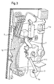
- FIG. 2 shows a further preferred embodiment of the invention.
- a mounting system 1 has a flexible hose part 2 which has a cooling pipe 7 at its second end 6.
- This cooling tube is flattened in this embodiment, whereby it particularly well adapts to the shape of three triacs 11a, 11b, 11c and thus achieves a particularly effective cooling.
- the cooling tube 7 has a union nut 5b, with which it can be screwed to the water heater.
- Fig. 3 shows a flow heater comprising a mounting system 1.
- the water heater to a base support 9, which can be attached to a wall, and can serve as a mounting wall.
- a mounting adapter to the assembly z. B. to facilitate wall unevenness.
- the water heater to technical assemblies, which are arranged in a housing and are combined in a main component 10.
- This main component 10 is connectable and detachable in one piece with the base support 9.
- the mounting system 1 in this case has a flexible hose part 2, which has at its first end 3 a connecting pipe 4 with a union nut 5a.
- the flexible hose part 2 has a rigid cooling tube 7, which is fixed to the flexible hose part 2 and connected to it.
- the cooling tube 7 is adapted in shape to the shape of the triac 11 a, and thus causes a particularly effective cooling.
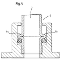
- Fig. 4 shows a detailed view of a first end 3 of a flexible hose part, which has a double eyelet 8a and 8b. Below the double flange 8a and 8b, an O-ring is provided, which compensates for possible manufacturing tolerances in the sealing seat.
- the present invention can be summarized as follows:
- a flexible hose part which is equipped at its one end with a union nut is connected in a preferred embodiment at the other end by a suitable joining method with a rigid copper tube.
- the copper tube is also flattened in the central area and led through the power section of the board, which serves to cool the triacs.
- the copper pipe is equipped with a double flare, which realizes the assembly function in the contact point of the heating block. Due to the fixed connection of the flexible hose part with the cooling tube eliminates the use of a sealing point. Screwing both components is eliminated.
- the mounting system according to the invention for a water heater allows a particularly safe and cost-effective installation.
Landscapes
- Engineering & Computer Science (AREA)
- Physics & Mathematics (AREA)
- Thermal Sciences (AREA)
- Chemical & Material Sciences (AREA)
- Combustion & Propulsion (AREA)
- Mechanical Engineering (AREA)
- General Engineering & Computer Science (AREA)
- Pipe Accessories (AREA)
Abstract
Description
- Die vorliegende Erfindung betrifft ein Montagesystem für Durchlauferhitzer, wenigstens umfassend ein flexibles Schlauchteil, wobei das flexible Schlauchteil an seinem ersten Ende ein Anschlussrohr mit einer Überwurfmutter aufweist.
- Montagesysteme für Durchlauferhitzer sind im Stand der Technik bekannt. In der Regel haben elektrische Durchlauferhitzer eine rückwärtige Montagewand, an der ein elektrischer Heizblock sowie sämtliche elektrische und hydraulische Schalteinrichtungen, angebracht sind. Mit dem Heizblock sind Wasseranschlussrohrleitungen für die Kaltwasserzuführungen und die Heißwasserabführungen verbunden, die wiederum an Wasseranschlussstücke, z. B. an der Zapfarmatur angeschraubt sind. Um ein Verbindungsanschluss der Wasseranschlussrohrleitungen beispielsweise an räumlich abweichende Wasseranschlüsse herstellen zu können, sind die Wasseranschlussrohrleitungen von Haus aus mit Rohrbögen versehen, die so groß gestaltet sind, dass über ihre Länge bzw. über ihren Radius eine Abstimmung in alle Richtungen vorgenommen werden kann. Als nachteilig wird bei dieser Lösung vor allem der große Materialeinsatz bei dem in der Regel aus Metall bestehenden Wasseranschlussrohrleitungen so wie der dafür notwendige größere Raumbedarf für die Unterbringung der Rohrleitungen Durchlauferhitzergehäuse angesehen.
- Hiervon ausgehend liegt der vorliegenden Erfindung die Aufgabe zu Grunde, die Montage zu vereinfachen und kostengünstiger zu gestalten.
- Gelöst wird diese Aufgabe mit den Merkmalen des Patentanspruches 1. Vorteilhafte Aus- und Weiterbildungen der Erfindungen, welche einzeln oder in Kombination miteinander eingesetzt werden können, sind Gegenstand der Unteransprüche.
- Das erfindungsgemäße Montagesystem baut auf gattungsgemäßen Montagesystemen dadurch auf, dass das flexible Schlauchteil an seinem zweiten Ende ein starres Kühlrohr aufweist, welches mit dem flexiblen Schlauchteil fest und dauerhaft verbunden ist. Dadurch wird gegenüber dem Stand der Technik eine beträchtliche Verbesserung der Montagesituation erreicht. Dadurch, dass eine Kombination von flexiblem Schlauchteil und Kühlrohr eingebaut werden kann, wird die Montage beschleunigt. Durch die feste Verbindung des flexiblen Schlauchteils mit dem Kühlrohr entfällt der Einsatz einer Dichtstelle. Ein Verschrauben beider Komponenten entfällt.
- In einer bevorzugten Ausführungsform erfolgt die feste und dauerhafte Verbindung zwischen dem flexiblen Schlauchteil und dem starren Kühlrohr mittels Schweißen und/oder Verkleben. Dies bewirkt eine sehr kostengünstige und zugleich sehr zuverlässige und sichere Verbindung beider Teile.
- Es hat sich als vorteilhaft erwiesen, wenn das flexible Schlauchteil Metall umfasst. Dabei wird bevorzugt Kupfer verwendet.
- In einer weiteren bevorzugten Ausführungsform weist das flexible Schlauchteil einen Innenschlauch und einen Außenschlauch auf. Dabei weist in einer bevorzugten Ausführungsform der Außenschlauch eine Umflechtung auf. Bevorzugt umfasst diese Umflechtung ein Edelstahl.
- Es hat sich aber auch als vorteilhaft erwiesen, wenn der Innenschlauch von einem thermoplastischen Elastomer, und/oder einem Polyamidgeflecht und/oder einem Edelstahlgeflecht und/oder einem zweiten thermoplastischen Elastomer umhüllt ist.
- Der Innenschlauch kann aber auch PEX und/oder Silikon umfassen, welches ein kreuzweise vernetztes Polymer darstellt. Auf Grund seiner kreuzweisen Vernetzung weist ein solcher Innenschlauch aus PEX eine besonders vorteilhafte Elastizität und Festigkeit auf.
- Es hat sich auch als vorteilhaft erwiesen, wenn das Kühlrohr eine abgeflachte Form aufweist. Dies ermöglicht es, dass in einer bevorzugten Ausführungsform die Form an die Triacs angepasst ist. Dadurch kann das Kühlrohr flächig an den Triacs anliegen, und überschüssige Wärme von dem Triacs aufnehmen. Dies bewirkt auf der einen Seite, dass die Triacs abgekühlt werden, und andererseits, dass das durch das Kühlrohr strömende Wasser erwärmt wird, und somit Energie eingespart wird.
- In einer weiteren bevorzugten Ausführungsform weist das flexible Schlauchteil an seinem ersten Ende einen Doppelbördel auf. Dies ermöglicht eine sichere und kostengünstige Installation bzw. Anschlusstechnik.
- Eine besonders bevorzugte Ausführungsform weist einen Durchlauferhitzer auf, der ein-Montagesystem für einen Durchlauferhitzer umfasst, wobei der Durchlauferhitzer einen Grundträger aufweist, sowie technische Baugruppen, die in einem Gehäuse angeordnet sind, und die technischen Baugruppen des Durchlauferhitzers mit einer Hauptkomponente vereinigt sind, und diese in einem Stück mit dem Grundträger verbind- und lösbar sind. Dadurch können nach Anbringen des Grundträgers an der Wand die technischen Baugruppen des Durchlauferhitzers schnell montiert, und im Reparaturfall entnommen und gewartet werden.
- Als vorteilhaft hat es sich auch erwiesen, wenn an das Montagesystem für Durchlauferhitzer wenigstens eine für den elektrischen sicheren Betrieb erforderliche Erdungsleitung angeschweißt und/oder angelötet ist. Besonders vorteilhaft ist es dabei, wenn durch das Aufpressen eines Übergangstückes ein elektrischer Widerstand von 0,01 bis 1,0, bevorzugt 0,1 Ohm erreicht wird.
- Das erfindungsgemäße Montagesystem für einen Durchlauferhitzer ermöglicht eine besonders sichere und kostengünstige Montage.
- Weitere Vorteile und Ausgestaltungen der Erfindung werden im Folgenden anhand von Ausführungsbeispielen sowie unter Bezugnahme auf die beiliegenden Zeichnungen erläutert.
- Darin zeigen schematisch:
- Fig. 1
- eine erste Ausführungsform eines Montagesystems für Durchlauferhitzer; und
- Fig. 2
- eine zweite Ausführungsform eines Montagesystems für Durchlauferhitzer; und
- Fig. 3
- eine weitere Ausführungsform eines Durchlauferhitzers mit Montagesys- tem; sowie
- Fig. 4
- eine Detaildarstellung zeigt eine Detaildarstellung eines ersten Endes eines flexiblen Schlauchteils.
- Bei der nachfolgenden Beschreibung der bevorzugten Ausführungsformen der vorliegenden Erfindung bezeichnen gleiche Bezugszeichen gleiche oder vergleichbare Komponenten.
-
Fig. 1 zeigt in einer schematischen Darstellung eine Ausführungsform eines Montagesystems 1 für Durchlauferhitzer. Dieses Montagesystem 1 weist ein flexibles Schlauchteil 2 auf, welches an seinem ersten Ende 3 ein Anschlussrohr 4 mit Überwurfmutter 5a aufweist. An seinem zweiten Ende 6 weist das Montagesystem 1 ein Kühlrohr 7 auf, welches an seinem geräteseitigen Ende eine Überwurfmutter 5b aufweist. Dabei ist das Kühlrohr 7 abgeflacht, um sich an die Form der Triacs anzupassen, und eine besonders effektive Kühlung zu bewirken. -
Fig. 2 zeigt eine weitere bevorzugte Ausführungsform der Erfindung. Ein Montagesystem 1 weist ein flexibles Schlauchteil 2 auf, welches an seinem zweiten Ende 6 ein Kühlrohr 7 aufweist. Dieses Kühlrohr ist in dieser Ausführungsform abgeflacht, wodurch es sich besonders gut an die Form dreier Triacs 11a, 11b, 11c anpasst und so eine besonders effektive Kühlung erzielt. An seinem geräteseitigen Ende weist das Kühlrohr 7 eine Überwurfmutter 5b auf, mit der es mit dem Durchlauferhitzer verschraubt werden kann. -
Fig. 3 zeigt einen Durchlauferhitzer, der ein Montagesystem 1 umfasst. Dabei weist der Durchlauferhitzer einen Grundträger 9 auf, der an einer Wand befestigt werden kann, und als Montagewand dienen kann. Es ist aber auch denkbar, an den Grundträger 3 auf der der Wand zugewandten Seite ein Montagezwischenstück einzufügen, um die Montage z. B. bei Wandunebenheiten zu erleichtern. Darüber hinaus weist der Durchlauferhitzer technische Baugruppen auf, die in einem Gehäuse angeordnet sind und in einer Hauptkomponente 10 vereinigt sind. Diese Hauptkomponente 10 ist in einem Stück mit dem Grundträger 9 verbind- und lösbar. Das Montagesystem 1 weist hierbei ein flexibles Schlauchteil 2 auf, welches an seinem ersten Ende 3 ein Anschlussrohr 4 mit einer Überwurfmutter 5a aufweist. An seinem zweiten Ende 6 (nicht abgebildet) weist das flexible Schlauchteil 2 ein starres Kühlrohr 7 auf, welches mit dem flexiblen Schlauchteil 2 fest und darauf verbunden ist. Das Kühlrohr 7 ist in seiner Form an die Form des Triacs 11a angepasst, und bewirkt so eine besonders effektive Kühlung. -
Fig. 4 zeigt eine Detaildarstellung eines ersten Endes 3 eines flexiblen Schlauchteils, welches einen Doppelbördel 8a bzw. 8b aufweist. Unterhalb des Doppelbördels 8a bzw. 8b ist ein O-Ring vorgesehen, welcher mögliche Fertigungstoleranzen im Dichtsitz ausgleicht. - Die vorliegende Erfindung lässt sich wie folgt zusammenfassen:
- Ein flexibles Schlauchteil, das an seinem einem Ende mit einer Überwurfmutter ausgerüstet ist, wird in einer bevorzugten Ausführungsform am anderen Ende durch ein geeignetes Fügeverfahren mit einem starren Kupferrohr verbunden. Das Kupferrohr wird zudem im mittleren Bereich abgeflacht und durch den Leistungsteil der Platine geführt, was der Kühlung der Triacs dient. Am anderen Ende ist das Kupferrohr mit einem Doppelbördel ausgerüstet, welche die Montagefunktion in der Kontaktstelle des Heizblocks realisiert. Durch die feste Verbindung des flexiblen Schlauchteils mit dem Kühlrohr entfällt der Einsatz einer Dichtstelle. Ein Verschrauben beider Komponenten entfällt.
- Das erfindungsgemäße Montagesystem für einen Durchlauferhitzer ermöglicht eine besonders sichere und kostengünstige Montage.
-
- 1
- Montagesystem
- 2
- Flexibles Schlauchteil
- 3
- Erstes Ende des flexiblen Schlauchteils
- 4
- Anschlussrohr
- 5a, 5b
- Überwurfmutter
- 6
- Zweites Ende des flexiblen Schlauchteils
- 7
- Kühlrohr
- 8a, 8b
- Doppelbördel
- 9
- Grundträger
- 10
- Hauptkomponente
- 11a, 11b, 11c
- Triac
Claims (9)
- Montagesystem (1) für Durchlauferhitzer, wenigstens umfassend ein flexibles Schlauchteil (2) wobei das flexible Schlauchteil (2) an seinem ersten Ende (3) ein Anschlussrohr (4) mit Überwurfmutter (5) aufweist, dadurch gekennzeichnet, dass das flexible Schlauchteil (2) an seinem zweiten Ende (6) ein starres Kühlrohr (7) aufweist, welches mit dem flexiblen Schlauchteil (2) fest und dauerhaft verbunden ist.
- Montagesystem (1) für Durchlauferhitzer nach Anspruch 1, dadurch gekennzeichnet, dass die feste und dauerhafte Verbindung zwischen flexiblen Schlauchteil (2) und starrem Kühlrohr (7) mittels Schweißen und/oder Verkleben erfolgt.
- Montagesystem (1) für Durchlauferhitzer nach Anspruch 1 oder 2, dadurch gekennzeichnet, dass das flexible Schlauchteil (2) ein Metall umfasst.
- Montagesystem (1) für Durchlauferhitzer nach einem der vorhergehenden Ansprüche, dadurch gekennzeichnet, dass das flexible Schlauchteil (2) einen Innenschlauch und einen Außenschlauch umfasst.
- Montagesystem (1) für Durchlauferhitzer nach einem der vorhergehenden Ansprüche, dadurch gekennzeichnet, dass das Kühlrohr (7) eine abgeflachte Form aufweist.
- Montagesystem (1) für Durchlauferhitzer nach Anspruch 5, dadurch gekennzeichnet, dass die abgeflachte Form an die Form von Triacs (11a, 11b, 11c) angepasst ist.
- Montagesystem (1) für Durchlauferhitzer nach einem der vorhergehenden Ansprüche, dadurch gekennzeichnet, dass das flexible Schlauchteil (2) an seinem ersten Ende (3) einen Doppelbördel (8a, 8b) aufweist.
- Montagesystem (1) für Durchlauferhitzer nach einem der vorhergehenden Ansprüche, dadurch gekennzeichnet, dass der Durchlauferhitzer einen Grundträger (9) aufweist, sowie technische Baugruppen, die in einem Gehäuse angeordnet sind, und die technischen Baugruppen des Durchlauferhitzers mit einer Hauptkomponente (10) vereinigt sind, und diese Hauptkomponente (10) in einem Stück mit dem Grundträger (9) verbind- und lösbar ist.
- Montagesystem (1) für Durchlauferhitzer nach einem der vorhergehenden Ansprüche, dadurch gekennzeichnet, dass an das Montagesystem eine Erdungsleitung angeschweißt und/oder angelötet ist.
Applications Claiming Priority (1)
| Application Number | Priority Date | Filing Date | Title |
|---|---|---|---|
| DE102008037681A DE102008037681A1 (de) | 2008-08-14 | 2008-08-14 | Montagesystem für Durchlauferhitzer |
Publications (3)
| Publication Number | Publication Date |
|---|---|
| EP2154446A2 true EP2154446A2 (de) | 2010-02-17 |
| EP2154446A3 EP2154446A3 (de) | 2016-02-10 |
| EP2154446B1 EP2154446B1 (de) | 2017-11-22 |
Family
ID=41066455
Family Applications (1)
| Application Number | Title | Priority Date | Filing Date |
|---|---|---|---|
| EP09167138.8A Not-in-force EP2154446B1 (de) | 2008-08-14 | 2009-08-04 | Montagesystem für Durchlauferhitzer |
Country Status (3)
| Country | Link |
|---|---|
| EP (1) | EP2154446B1 (de) |
| DE (1) | DE102008037681A1 (de) |
| PT (1) | PT2154446T (de) |
Family Cites Families (2)
| Publication number | Priority date | Publication date | Assignee | Title |
|---|---|---|---|---|
| DE202004012263U1 (de) * | 2004-08-05 | 2004-10-07 | Stiebel Eltron Gmbh & Co. Kg | Durchlauferhitzer |
| DE102006039498A1 (de) * | 2006-08-23 | 2008-02-28 | BSH Bosch und Siemens Hausgeräte GmbH | Durchlauferhitzer zur Schnellmontage |
-
2008
- 2008-08-14 DE DE102008037681A patent/DE102008037681A1/de not_active Ceased
-
2009
- 2009-08-04 EP EP09167138.8A patent/EP2154446B1/de not_active Not-in-force
- 2009-08-04 PT PT91671388T patent/PT2154446T/pt unknown
Also Published As
| Publication number | Publication date |
|---|---|
| EP2154446A3 (de) | 2016-02-10 |
| PT2154446T (pt) | 2018-02-16 |
| EP2154446B1 (de) | 2017-11-22 |
| DE102008037681A1 (de) | 2010-02-18 |
Similar Documents
| Publication | Publication Date | Title |
|---|---|---|
| EP2592982B1 (de) | Dynamischer durchlauferhitzer | |
| EP2957681B1 (de) | Sanitärarmatur mit innenschlauchanordnung | |
| DE202013006214U1 (de) | Wärmetauscher | |
| DE102010031520A1 (de) | Elektrischer Heizkörper und Durchlauferhitzer | |
| EP2154446B1 (de) | Montagesystem für Durchlauferhitzer | |
| DE202005019499U1 (de) | Beheizung eines Tanks für Harnstoffwasserlösung | |
| DE102008037680A1 (de) | Zu- und Auslaufrohr für einen Durchlauferhitzer | |
| DE10250305A1 (de) | Dichtendes Verbindungswellrohr für Solaranlagen und sonstige Anschlüsse | |
| EP3390731A1 (de) | Vorrichtung zur verbindung zumindest einer armatur und einer leitung mit thermischer entkopplung | |
| DE202019104006U1 (de) | Modularer Verteiler für Rohrinstallationen | |
| DE102013101792B4 (de) | Wärmepumpe | |
| EP1101534B1 (de) | Heizbare Düse für den Einsatz in Scheibenwaschanlagen | |
| DE202004002219U1 (de) | Anschlußelement für Sonnenkollektoren | |
| WO2008022888A1 (de) | Durchlauferhitzer zur schnellmontage | |
| EP2444744B1 (de) | Baugruppe zum Aufbau eines Heizkörpers | |
| DE4208675C2 (de) | Elektrischer Durchlauferhitzer | |
| EP2060855B1 (de) | Wasserzirkulationsleitung mit einem Abschlussstück und Verfahren zum Montieren einer solchen Wasserzirkulationsleitung | |
| EP1918666A1 (de) | Rohrheizkörper | |
| EP2369964B1 (de) | Strangheizkörper | |
| AT411553B (de) | Anschlussarmatur für einen plattenheizkörper | |
| DE202009017485U1 (de) | Soleverteiler für Erdwärmesonden | |
| DE102022131377A1 (de) | Heizeinheit für ein elektrisches Heizgerät, Heizgerät und Verfahren zur Herstellung einer Heizeinheit | |
| DE102013215864A1 (de) | Dichtungsanordnung für ein Fluid führendes Rohr | |
| DE10060316A1 (de) | Beheizbarer Schlauch zur Zuführung von strömungsfähigen Medien, insbesondere von Wasser und Wassergemischen, in einer Kfz-Waschanlage | |
| EP2184412B1 (de) | Fluidführende Vorrichtung |
Legal Events
| Date | Code | Title | Description |
|---|---|---|---|
| PUAI | Public reference made under article 153(3) epc to a published international application that has entered the european phase |
Free format text: ORIGINAL CODE: 0009012 |
|
| AK | Designated contracting states |
Kind code of ref document: A2 Designated state(s): AT BE BG CH CY CZ DE DK EE ES FI FR GB GR HR HU IE IS IT LI LT LU LV MC MK MT NL NO PL PT RO SE SI SK SM TR |
|
| AX | Request for extension of the european patent |
Extension state: AL BA RS |
|
| RAP1 | Party data changed (applicant data changed or rights of an application transferred) |
Owner name: BSH HAUSGERAETE GMBH |
|
| PUAL | Search report despatched |
Free format text: ORIGINAL CODE: 0009013 |
|
| AK | Designated contracting states |
Kind code of ref document: A3 Designated state(s): AT BE BG CH CY CZ DE DK EE ES FI FR GB GR HR HU IE IS IT LI LT LU LV MC MK MT NL NO PL PT RO SE SI SK SM TR |
|
| AX | Request for extension of the european patent |
Extension state: AL BA RS |
|
| RIC1 | Information provided on ipc code assigned before grant |
Ipc: F24H 9/14 20060101ALI20160105BHEP Ipc: F24H 9/06 20060101AFI20160105BHEP |
|
| 17P | Request for examination filed |
Effective date: 20160810 |
|
| RBV | Designated contracting states (corrected) |
Designated state(s): AT BE BG CH CY CZ DE DK EE ES FI FR GB GR HR HU IE IS IT LI LT LU LV MC MK MT NL NO PL PT RO SE SI SK SM TR |
|
| GRAP | Despatch of communication of intention to grant a patent |
Free format text: ORIGINAL CODE: EPIDOSNIGR1 |
|
| RIC1 | Information provided on ipc code assigned before grant |
Ipc: F24H 9/06 20060101AFI20170526BHEP Ipc: F24H 9/14 20060101ALI20170526BHEP |
|
| INTG | Intention to grant announced |
Effective date: 20170704 |
|
| GRAS | Grant fee paid |
Free format text: ORIGINAL CODE: EPIDOSNIGR3 |
|
| GRAA | (expected) grant |
Free format text: ORIGINAL CODE: 0009210 |
|
| AK | Designated contracting states |
Kind code of ref document: B1 Designated state(s): AT BE BG CH CY CZ DE DK EE ES FI FR GB GR HR HU IE IS IT LI LT LU LV MC MK MT NL NO PL PT RO SE SI SK SM TR |
|
| REG | Reference to a national code |
Ref country code: GB Ref legal event code: FG4D Free format text: NOT ENGLISH |
|
| REG | Reference to a national code |
Ref country code: CH Ref legal event code: EP |
|
| REG | Reference to a national code |
Ref country code: IE Ref legal event code: FG4D Free format text: LANGUAGE OF EP DOCUMENT: GERMAN |
|
| REG | Reference to a national code |
Ref country code: AT Ref legal event code: REF Ref document number: 948785 Country of ref document: AT Kind code of ref document: T Effective date: 20171215 |
|
| REG | Reference to a national code |
Ref country code: DE Ref legal event code: R096 Ref document number: 502009014544 Country of ref document: DE |
|
| REG | Reference to a national code |
Ref country code: PT Ref legal event code: SC4A Ref document number: 2154446 Country of ref document: PT Date of ref document: 20180216 Kind code of ref document: T Free format text: AVAILABILITY OF NATIONAL TRANSLATION Effective date: 20180207 |
|
| REG | Reference to a national code |
Ref country code: NL Ref legal event code: MP Effective date: 20171122 |
|
| REG | Reference to a national code |
Ref country code: LT Ref legal event code: MG4D |
|
| PG25 | Lapsed in a contracting state [announced via postgrant information from national office to epo] |
Ref country code: NL Free format text: LAPSE BECAUSE OF FAILURE TO SUBMIT A TRANSLATION OF THE DESCRIPTION OR TO PAY THE FEE WITHIN THE PRESCRIBED TIME-LIMIT Effective date: 20171122 Ref country code: LT Free format text: LAPSE BECAUSE OF FAILURE TO SUBMIT A TRANSLATION OF THE DESCRIPTION OR TO PAY THE FEE WITHIN THE PRESCRIBED TIME-LIMIT Effective date: 20171122 Ref country code: SE Free format text: LAPSE BECAUSE OF FAILURE TO SUBMIT A TRANSLATION OF THE DESCRIPTION OR TO PAY THE FEE WITHIN THE PRESCRIBED TIME-LIMIT Effective date: 20171122 Ref country code: NO Free format text: LAPSE BECAUSE OF FAILURE TO SUBMIT A TRANSLATION OF THE DESCRIPTION OR TO PAY THE FEE WITHIN THE PRESCRIBED TIME-LIMIT Effective date: 20180222 Ref country code: ES Free format text: LAPSE BECAUSE OF FAILURE TO SUBMIT A TRANSLATION OF THE DESCRIPTION OR TO PAY THE FEE WITHIN THE PRESCRIBED TIME-LIMIT Effective date: 20171122 Ref country code: FI Free format text: LAPSE BECAUSE OF FAILURE TO SUBMIT A TRANSLATION OF THE DESCRIPTION OR TO PAY THE FEE WITHIN THE PRESCRIBED TIME-LIMIT Effective date: 20171122 |
|
| PG25 | Lapsed in a contracting state [announced via postgrant information from national office to epo] |
Ref country code: GR Free format text: LAPSE BECAUSE OF FAILURE TO SUBMIT A TRANSLATION OF THE DESCRIPTION OR TO PAY THE FEE WITHIN THE PRESCRIBED TIME-LIMIT Effective date: 20180223 Ref country code: BG Free format text: LAPSE BECAUSE OF FAILURE TO SUBMIT A TRANSLATION OF THE DESCRIPTION OR TO PAY THE FEE WITHIN THE PRESCRIBED TIME-LIMIT Effective date: 20180222 Ref country code: LV Free format text: LAPSE BECAUSE OF FAILURE TO SUBMIT A TRANSLATION OF THE DESCRIPTION OR TO PAY THE FEE WITHIN THE PRESCRIBED TIME-LIMIT Effective date: 20171122 Ref country code: HR Free format text: LAPSE BECAUSE OF FAILURE TO SUBMIT A TRANSLATION OF THE DESCRIPTION OR TO PAY THE FEE WITHIN THE PRESCRIBED TIME-LIMIT Effective date: 20171122 |
|
| PG25 | Lapsed in a contracting state [announced via postgrant information from national office to epo] |
Ref country code: DK Free format text: LAPSE BECAUSE OF FAILURE TO SUBMIT A TRANSLATION OF THE DESCRIPTION OR TO PAY THE FEE WITHIN THE PRESCRIBED TIME-LIMIT Effective date: 20171122 Ref country code: CZ Free format text: LAPSE BECAUSE OF FAILURE TO SUBMIT A TRANSLATION OF THE DESCRIPTION OR TO PAY THE FEE WITHIN THE PRESCRIBED TIME-LIMIT Effective date: 20171122 Ref country code: EE Free format text: LAPSE BECAUSE OF FAILURE TO SUBMIT A TRANSLATION OF THE DESCRIPTION OR TO PAY THE FEE WITHIN THE PRESCRIBED TIME-LIMIT Effective date: 20171122 Ref country code: CY Free format text: LAPSE BECAUSE OF FAILURE TO SUBMIT A TRANSLATION OF THE DESCRIPTION OR TO PAY THE FEE WITHIN THE PRESCRIBED TIME-LIMIT Effective date: 20171122 Ref country code: SK Free format text: LAPSE BECAUSE OF FAILURE TO SUBMIT A TRANSLATION OF THE DESCRIPTION OR TO PAY THE FEE WITHIN THE PRESCRIBED TIME-LIMIT Effective date: 20171122 |
|
| REG | Reference to a national code |
Ref country code: DE Ref legal event code: R097 Ref document number: 502009014544 Country of ref document: DE |
|
| REG | Reference to a national code |
Ref country code: FR Ref legal event code: PLFP Year of fee payment: 10 |
|
| PG25 | Lapsed in a contracting state [announced via postgrant information from national office to epo] |
Ref country code: IT Free format text: LAPSE BECAUSE OF FAILURE TO SUBMIT A TRANSLATION OF THE DESCRIPTION OR TO PAY THE FEE WITHIN THE PRESCRIBED TIME-LIMIT Effective date: 20171122 Ref country code: RO Free format text: LAPSE BECAUSE OF FAILURE TO SUBMIT A TRANSLATION OF THE DESCRIPTION OR TO PAY THE FEE WITHIN THE PRESCRIBED TIME-LIMIT Effective date: 20171122 Ref country code: SM Free format text: LAPSE BECAUSE OF FAILURE TO SUBMIT A TRANSLATION OF THE DESCRIPTION OR TO PAY THE FEE WITHIN THE PRESCRIBED TIME-LIMIT Effective date: 20171122 Ref country code: PL Free format text: LAPSE BECAUSE OF FAILURE TO SUBMIT A TRANSLATION OF THE DESCRIPTION OR TO PAY THE FEE WITHIN THE PRESCRIBED TIME-LIMIT Effective date: 20171122 |
|
| PG25 | Lapsed in a contracting state [announced via postgrant information from national office to epo] |
Ref country code: MT Free format text: LAPSE BECAUSE OF FAILURE TO SUBMIT A TRANSLATION OF THE DESCRIPTION OR TO PAY THE FEE WITHIN THE PRESCRIBED TIME-LIMIT Effective date: 20171122 |
|
| PLBE | No opposition filed within time limit |
Free format text: ORIGINAL CODE: 0009261 |
|
| STAA | Information on the status of an ep patent application or granted ep patent |
Free format text: STATUS: NO OPPOSITION FILED WITHIN TIME LIMIT |
|
| 26N | No opposition filed |
Effective date: 20180823 |
|
| PG25 | Lapsed in a contracting state [announced via postgrant information from national office to epo] |
Ref country code: SI Free format text: LAPSE BECAUSE OF FAILURE TO SUBMIT A TRANSLATION OF THE DESCRIPTION OR TO PAY THE FEE WITHIN THE PRESCRIBED TIME-LIMIT Effective date: 20171122 |
|
| PGFP | Annual fee paid to national office [announced via postgrant information from national office to epo] |
Ref country code: DE Payment date: 20181024 Year of fee payment: 10 |
|
| PG25 | Lapsed in a contracting state [announced via postgrant information from national office to epo] |
Ref country code: MC Free format text: LAPSE BECAUSE OF FAILURE TO SUBMIT A TRANSLATION OF THE DESCRIPTION OR TO PAY THE FEE WITHIN THE PRESCRIBED TIME-LIMIT Effective date: 20171122 |
|
| REG | Reference to a national code |
Ref country code: CH Ref legal event code: PL |
|
| PG25 | Lapsed in a contracting state [announced via postgrant information from national office to epo] |
Ref country code: LI Free format text: LAPSE BECAUSE OF NON-PAYMENT OF DUE FEES Effective date: 20180831 Ref country code: CH Free format text: LAPSE BECAUSE OF NON-PAYMENT OF DUE FEES Effective date: 20180831 Ref country code: LU Free format text: LAPSE BECAUSE OF NON-PAYMENT OF DUE FEES Effective date: 20180804 |
|
| REG | Reference to a national code |
Ref country code: BE Ref legal event code: MM Effective date: 20180831 |
|
| REG | Reference to a national code |
Ref country code: IE Ref legal event code: MM4A |
|
| PG25 | Lapsed in a contracting state [announced via postgrant information from national office to epo] |
Ref country code: IE Free format text: LAPSE BECAUSE OF NON-PAYMENT OF DUE FEES Effective date: 20180804 |
|
| PG25 | Lapsed in a contracting state [announced via postgrant information from national office to epo] |
Ref country code: BE Free format text: LAPSE BECAUSE OF NON-PAYMENT OF DUE FEES Effective date: 20180831 |
|
| REG | Reference to a national code |
Ref country code: AT Ref legal event code: MM01 Ref document number: 948785 Country of ref document: AT Kind code of ref document: T Effective date: 20180804 |
|
| PGFP | Annual fee paid to national office [announced via postgrant information from national office to epo] |
Ref country code: FR Payment date: 20190822 Year of fee payment: 11 Ref country code: PT Payment date: 20190729 Year of fee payment: 11 |
|
| PG25 | Lapsed in a contracting state [announced via postgrant information from national office to epo] |
Ref country code: AT Free format text: LAPSE BECAUSE OF NON-PAYMENT OF DUE FEES Effective date: 20180804 |
|
| PGFP | Annual fee paid to national office [announced via postgrant information from national office to epo] |
Ref country code: GB Payment date: 20190827 Year of fee payment: 11 |
|
| REG | Reference to a national code |
Ref country code: DE Ref legal event code: R119 Ref document number: 502009014544 Country of ref document: DE |
|
| PG25 | Lapsed in a contracting state [announced via postgrant information from national office to epo] |
Ref country code: TR Free format text: LAPSE BECAUSE OF FAILURE TO SUBMIT A TRANSLATION OF THE DESCRIPTION OR TO PAY THE FEE WITHIN THE PRESCRIBED TIME-LIMIT Effective date: 20171122 |
|
| PG25 | Lapsed in a contracting state [announced via postgrant information from national office to epo] |
Ref country code: HU Free format text: LAPSE BECAUSE OF FAILURE TO SUBMIT A TRANSLATION OF THE DESCRIPTION OR TO PAY THE FEE WITHIN THE PRESCRIBED TIME-LIMIT; INVALID AB INITIO Effective date: 20090804 |
|
| PG25 | Lapsed in a contracting state [announced via postgrant information from national office to epo] |
Ref country code: MK Free format text: LAPSE BECAUSE OF NON-PAYMENT OF DUE FEES Effective date: 20171122 |
|
| PG25 | Lapsed in a contracting state [announced via postgrant information from national office to epo] |
Ref country code: DE Free format text: LAPSE BECAUSE OF NON-PAYMENT OF DUE FEES Effective date: 20200303 Ref country code: IS Free format text: LAPSE BECAUSE OF FAILURE TO SUBMIT A TRANSLATION OF THE DESCRIPTION OR TO PAY THE FEE WITHIN THE PRESCRIBED TIME-LIMIT Effective date: 20180322 |
|
| GBPC | Gb: european patent ceased through non-payment of renewal fee |
Effective date: 20200804 |
|
| PG25 | Lapsed in a contracting state [announced via postgrant information from national office to epo] |
Ref country code: PT Free format text: LAPSE BECAUSE OF NON-PAYMENT OF DUE FEES Effective date: 20210304 |
|
| PG25 | Lapsed in a contracting state [announced via postgrant information from national office to epo] |
Ref country code: FR Free format text: LAPSE BECAUSE OF NON-PAYMENT OF DUE FEES Effective date: 20200831 |
|
| PG25 | Lapsed in a contracting state [announced via postgrant information from national office to epo] |
Ref country code: GB Free format text: LAPSE BECAUSE OF NON-PAYMENT OF DUE FEES Effective date: 20200804 |