EP2154363A1 - Wind-driven generator and yaw rotation drive method for wind-driven generator - Google Patents
Wind-driven generator and yaw rotation drive method for wind-driven generator Download PDFInfo
- Publication number
- EP2154363A1 EP2154363A1 EP08764266A EP08764266A EP2154363A1 EP 2154363 A1 EP2154363 A1 EP 2154363A1 EP 08764266 A EP08764266 A EP 08764266A EP 08764266 A EP08764266 A EP 08764266A EP 2154363 A1 EP2154363 A1 EP 2154363A1
- Authority
- EP
- European Patent Office
- Prior art keywords
- wind
- command value
- yaw
- wind turbine
- around
- Prior art date
- Legal status (The legal status is an assumption and is not a legal conclusion. Google has not performed a legal analysis and makes no representation as to the accuracy of the status listed.)
- Granted
Links
Images



Classifications
-
- F—MECHANICAL ENGINEERING; LIGHTING; HEATING; WEAPONS; BLASTING
- F03—MACHINES OR ENGINES FOR LIQUIDS; WIND, SPRING, OR WEIGHT MOTORS; PRODUCING MECHANICAL POWER OR A REACTIVE PROPULSIVE THRUST, NOT OTHERWISE PROVIDED FOR
- F03D—WIND MOTORS
- F03D7/00—Controlling wind motors
- F03D7/02—Controlling wind motors the wind motors having rotation axis substantially parallel to the air flow entering the rotor
- F03D7/04—Automatic control; Regulation
- F03D7/042—Automatic control; Regulation by means of an electrical or electronic controller
-
- F—MECHANICAL ENGINEERING; LIGHTING; HEATING; WEAPONS; BLASTING
- F03—MACHINES OR ENGINES FOR LIQUIDS; WIND, SPRING, OR WEIGHT MOTORS; PRODUCING MECHANICAL POWER OR A REACTIVE PROPULSIVE THRUST, NOT OTHERWISE PROVIDED FOR
- F03D—WIND MOTORS
- F03D1/00—Wind motors with rotation axis substantially parallel to the air flow entering the rotor
- F03D1/06—Rotors
-
- F—MECHANICAL ENGINEERING; LIGHTING; HEATING; WEAPONS; BLASTING
- F03—MACHINES OR ENGINES FOR LIQUIDS; WIND, SPRING, OR WEIGHT MOTORS; PRODUCING MECHANICAL POWER OR A REACTIVE PROPULSIVE THRUST, NOT OTHERWISE PROVIDED FOR
- F03D—WIND MOTORS
- F03D7/00—Controlling wind motors
- F03D7/02—Controlling wind motors the wind motors having rotation axis substantially parallel to the air flow entering the rotor
- F03D7/0204—Controlling wind motors the wind motors having rotation axis substantially parallel to the air flow entering the rotor for orientation in relation to wind direction
-
- F—MECHANICAL ENGINEERING; LIGHTING; HEATING; WEAPONS; BLASTING
- F03—MACHINES OR ENGINES FOR LIQUIDS; WIND, SPRING, OR WEIGHT MOTORS; PRODUCING MECHANICAL POWER OR A REACTIVE PROPULSIVE THRUST, NOT OTHERWISE PROVIDED FOR
- F03D—WIND MOTORS
- F03D7/00—Controlling wind motors
- F03D7/02—Controlling wind motors the wind motors having rotation axis substantially parallel to the air flow entering the rotor
- F03D7/022—Adjusting aerodynamic properties of the blades
- F03D7/0224—Adjusting blade pitch
-
- F—MECHANICAL ENGINEERING; LIGHTING; HEATING; WEAPONS; BLASTING
- F05—INDEXING SCHEMES RELATING TO ENGINES OR PUMPS IN VARIOUS SUBCLASSES OF CLASSES F01-F04
- F05B—INDEXING SCHEME RELATING TO WIND, SPRING, WEIGHT, INERTIA OR LIKE MOTORS, TO MACHINES OR ENGINES FOR LIQUIDS COVERED BY SUBCLASSES F03B, F03D AND F03G
- F05B2260/00—Function
- F05B2260/96—Preventing, counteracting or reducing vibration or noise
-
- F—MECHANICAL ENGINEERING; LIGHTING; HEATING; WEAPONS; BLASTING
- F05—INDEXING SCHEMES RELATING TO ENGINES OR PUMPS IN VARIOUS SUBCLASSES OF CLASSES F01-F04
- F05B—INDEXING SCHEME RELATING TO WIND, SPRING, WEIGHT, INERTIA OR LIKE MOTORS, TO MACHINES OR ENGINES FOR LIQUIDS COVERED BY SUBCLASSES F03B, F03D AND F03G
- F05B2270/00—Control
- F05B2270/10—Purpose of the control system
- F05B2270/103—Purpose of the control system to affect the output of the engine
- F05B2270/1033—Power (if explicitly mentioned)
-
- F—MECHANICAL ENGINEERING; LIGHTING; HEATING; WEAPONS; BLASTING
- F05—INDEXING SCHEMES RELATING TO ENGINES OR PUMPS IN VARIOUS SUBCLASSES OF CLASSES F01-F04
- F05B—INDEXING SCHEME RELATING TO WIND, SPRING, WEIGHT, INERTIA OR LIKE MOTORS, TO MACHINES OR ENGINES FOR LIQUIDS COVERED BY SUBCLASSES F03B, F03D AND F03G
- F05B2270/00—Control
- F05B2270/30—Control parameters, e.g. input parameters
- F05B2270/321—Wind directions
-
- F—MECHANICAL ENGINEERING; LIGHTING; HEATING; WEAPONS; BLASTING
- F05—INDEXING SCHEMES RELATING TO ENGINES OR PUMPS IN VARIOUS SUBCLASSES OF CLASSES F01-F04
- F05B—INDEXING SCHEME RELATING TO WIND, SPRING, WEIGHT, INERTIA OR LIKE MOTORS, TO MACHINES OR ENGINES FOR LIQUIDS COVERED BY SUBCLASSES F03B, F03D AND F03G
- F05B2270/00—Control
- F05B2270/30—Control parameters, e.g. input parameters
- F05B2270/331—Mechanical loads
-
- F—MECHANICAL ENGINEERING; LIGHTING; HEATING; WEAPONS; BLASTING
- F05—INDEXING SCHEMES RELATING TO ENGINES OR PUMPS IN VARIOUS SUBCLASSES OF CLASSES F01-F04
- F05B—INDEXING SCHEME RELATING TO WIND, SPRING, WEIGHT, INERTIA OR LIKE MOTORS, TO MACHINES OR ENGINES FOR LIQUIDS COVERED BY SUBCLASSES F03B, F03D AND F03G
- F05B2270/00—Control
- F05B2270/80—Devices generating input signals, e.g. transducers, sensors, cameras or strain gauges
- F05B2270/804—Optical devices
-
- Y—GENERAL TAGGING OF NEW TECHNOLOGICAL DEVELOPMENTS; GENERAL TAGGING OF CROSS-SECTIONAL TECHNOLOGIES SPANNING OVER SEVERAL SECTIONS OF THE IPC; TECHNICAL SUBJECTS COVERED BY FORMER USPC CROSS-REFERENCE ART COLLECTIONS [XRACs] AND DIGESTS
- Y02—TECHNOLOGIES OR APPLICATIONS FOR MITIGATION OR ADAPTATION AGAINST CLIMATE CHANGE
- Y02E—REDUCTION OF GREENHOUSE GAS [GHG] EMISSIONS, RELATED TO ENERGY GENERATION, TRANSMISSION OR DISTRIBUTION
- Y02E10/00—Energy generation through renewable energy sources
- Y02E10/70—Wind energy
- Y02E10/72—Wind turbines with rotation axis in wind direction
Definitions
- the weight of the nacelle can be reduced, and it is possible to restrict power consumption by the yaw motor. It is also possible to eliminate the yaw motor. In such a case, further reduction in the size and weight of the nacelle is possible, and further reduction in power consumption is possible.
Landscapes
- Engineering & Computer Science (AREA)
- Life Sciences & Earth Sciences (AREA)
- Sustainable Development (AREA)
- Sustainable Energy (AREA)
- Chemical & Material Sciences (AREA)
- Combustion & Propulsion (AREA)
- Mechanical Engineering (AREA)
- General Engineering & Computer Science (AREA)
- Physics & Mathematics (AREA)
- Fluid Mechanics (AREA)
- Wind Motors (AREA)
Abstract
Description
- The present invention relates to a wind turbine generator and a yaw driving method for a wind turbine generator.
- Wind-turbine generating units having wind turbines and generators that are rotationally driven by the wind turbines are provided on wind turbine generators at the top of wind turbine towers in a manner capable of yaw rotation. The wind turbine generators are constructed such that the wind turbines receive wind force from the front and such that the wind-turbine generating unit yaws (turns in a substantially horizontal plane) with respect to the wind turbine tower in response to the wind direction.
In the wind turbine generators, yaw driving of the wind-turbine generating unit is carried out by securely disposing a ring gear on the tower, positioning a pinion that engages with the ring gear on the wind-turbine generating unit, and rotationally driving the pinion with a yaw motor (for example, see Patent Document 1).
Patent Document 1: - Japanese Unexamined Patent Application, Publication No.
2001-289149 - Recently, along with a size increase in wind turbines, the sizes of the yaw motors, ring gears, etc. have also increased. A yaw motor is frequently activated to carry out yaw driving of the nacelle, and since the size is increased, there is a further increase in power consumption.
When the size and weight of the nacelle are to be decreased, reducing the size and weight of the structure of the yaw motor, etc. is an important issue. - It is an object of the present invention to provide a wind turbine generator and a yaw driving method for the wind turbine generator in which it is possible to reduce power consumption in a nacelle and to reduce the size of the nacelle.
- To achieve the above-described object, the present invention provides the following solutions.
A first aspect of the present invention is a wind turbine generator including a load measurement unit configured to measure a load on each wind turbine blade; a moment calculating unit configured to calculate a moment around a wind-turbine tower axis by carrying out coordinate transformation of the load on each wind turbine blade measured by the load measurement unit; a component-command-value setting unit configured to calculate an angle command value around the wind-turbine tower axis by adding a yaw-control command value to a reference command value for canceling out the moment calculated by the moment calculating unit; and a pitch-angle-command setting unit configured to set a pitch-angle command value for each wind turbine blade on the basis of the angle command value around the wind-turbine tower axis. - A yaw-control command value is added to a reference command value for canceling out the load around a wind-turbine tower axis associated with each wind turbine blade in order to calculate an angle command value, and a pitch-angle command value of each wind turbine blade is set according to this angle command value; therefore, it is possible to turn (yaw) the nacelle around the wind-turbine tower, using a moment generated at the wind turbine blades corresponding to the yaw-control command value. In this way, by controlling the pitch angle of each wind turbine blade, the nacelle is turned using air force; therefore, it is possible to reduce the size and usage frequency of the yaw motor. As a result, the weight of the nacelle can be reduced, and it is possible to restrict power consumption by the yaw motor. It is also possible to eliminate the yaw motor. In such a case, further reduction in the size and weight of the nacelle is possible, and further reduction in power consumption is possible.
- In the wind turbine generator, the yaw-control command value may be provided to correspond to the wind direction.
- In this way, by providing a yaw-control command value corresponding to the wind direction, it is possible to turn the nacelle to an appropriate direction with respect to the wind direction.
- In the wind turbine generator, the yaw-control command value may be set, for example, on the basis of a wind direction deviation.
- A second aspect of the present invention is a yaw driving method for a wind turbine generator, the method including a step of measuring a load on each wind turbine blade; a step of calculating a moment around a wind-turbine tower axis by carrying out coordinate transformation of the load on each wind turbine blade; a step of calculating an angle command value around the wind-turbine tower axis by adding a yaw-control command value to a reference command value for making the moment zero; and a step of setting a pitch-angle control value for each wind turbine blade on the basis of the angle command value around the wind-turbine tower axis.
- The present invention is advantageous in that power consumption in the nacelle can be reduced, and the size of the nacelle can be reduced.
-
- [
Fig. 1] Fig. 1 illustrates the entire configuration of a wind turbine generator according to an embodiment of the present invention. - [
Fig. 2] Fig. 2 illustrates, in outline, the configuration inside a nacelle. - [
Fig. 3] Fig. 3 illustrates control blocks associated with pitch-angle control, provided in the wind turbine generator according to an embodiment of the present invention. - [
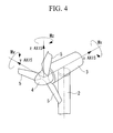
Fig. 4] Fig. 4 illustrates the definition of z, y, and z axes. - [
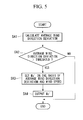
Fig. 5] Fig. 5 is a flow chart illustrating the processing procedure carried out by a yaw-control-command-value setting unit according to an embodiment of the present invention. - [
Fig. 6] Fig. 6 illustrates an example of a yaw-control-command-value table. -
- 1: wind turbine generator
- 2: wind turbine tower
- 3: nacelle
- 4: rotor head
- 5: wind turbine blade
- 7: anemometer
- 8: anemoscope
- 9: load measurement sensor
- 10: gearbox
- 11: generator
- 20: wind-turbine control device
- 21: variable pitch mechanism
- 31: moment calculating unit
- 32: component-command-value setting unit
- 33: pitch-angle-command setting unit
- 34: yaw-control-command-value setting unit
- An embodiment of wind turbine generator according to the present invention and a yaw driving method for a wind turbine generator will be described below with reference to the drawings.
Fig. 1 is a block diagram illustrating, in outline, the configuration of the wind turbine generator according to this embodiment.
As shown inFig. 1 , a wind turbine generator 1 has awind turbine tower 2, anacelle 3 installed at the top of thewind turbine tower 2, and arotor head 4 provided on thenacelle 3 in such a manner as to be rotatable around a substantially horizontal axis. A plurality ofwind turbine blades 5 is attached to therotor head 4 in a radiating pattern around the rotational axis thereof. As a result, the force of the wind striking thewind turbine blades 5 from the rotational axis direction of therotor head 4 is converted to motive energy causing therotor head 4 to rotate around the rotational axis. In this embodiment, a case in which threewind turbine blades 5 are provided will be described. - At appropriate positions (for example, at the top section) on the outer peripheral surface of the
nacelle 3, ananemometer 7 that measures the wind speed in the surroundings and ananemoscope 8 that measures the wind direction are installed. Each of thewind turbine blades 5 is provided with a load measurement sensor (for example, an optical fiber sensor) 9 for measuring the load on thewind turbine blade 5.
Theanemoscope 8 measures a wind-direction deviation and outputs the wind-direction deviation as a measured value. Theload measurement sensor 9, for example, measures the deformation of thewind turbine blade 5 and measures the load corresponding to the amount of deformation. - As shown in
Fig. 2 , agenerator 11 connected to therotor head 4 via acoaxial gearbox 10 is installed inside thenacelle 3. In other words, by speeding up the rotation of therotor head 4 with thegearbox 10 and driving thegenerator 11, a generator output is obtained from thegenerator 11. Moreover, a wind-turbine control device 20 that controls the operation of the wind turbine and avariable pitch mechanism 21 that receives a control signal from the wind-turbine control device 20 and changes the pitch angle of each wind turbine blade are provided inside thenacelle 3. - Load measurement values of the
wind turbine blades 5 measured by theload measurement sensors 9, wind-direction deviation measured by theanemoscope 8, and wind speed measured by theanemometer 7 are input to the wind-turbine control device 20. The wind-turbine control device 20 sets the pitch angles of thewind turbine blades 5 on the basis of such input information and outputs control signals corresponding to the set pitch angles to thevariable pitch mechanism 21. Thevariable pitch mechanism 21 changes the pitch angles of thewind turbine blades 5 on the basis of the control signals sent from the wind-turbine control device 20. -
Fig. 3 illustrates control blocks associated with pitch angle control, provided in the wind-turbine control device 20. As shown inFig. 3 , the wind-turbine control device 20 is equipped with amoment calculating unit 31, a component-command-value setting unit 32, a pitch-angle-command setting unit 33, and a yaw-control-command-value setting unit 34. - The
moment calculating unit 31 calculates a moment Mz around a z axis and a moment My around a y axis, which are shown inFig. 4 , by performing coordinate transformation of loads M1, M2, and M3 on thewind turbine blades 5 measured by theload measurement sensors 9. As shown inFig. 4 , the z axis is an axis parallel to the main axis of thewind turbine tower 2, the x axis is the rotational axis of therotor head 4, and the y axis is an axis orthogonal to the z axis and the x axis. - Upon calculation of the moments My and Mz, the
moment calculating unit 31 outputs them to the component-command-value setting unit 32. The component-command-value setting unit 32 sets an angle command value θy associated with the y axis and an angle command value θz associated with the z axis on the basis of the moments My and Mz calculated by themoment calculating unit 31. - More specifically, the component-command-
value setting unit 32 determines a reference command value that cancels out the moment My around the y axis and sets this reference command value as the angle command value θy around the y axis. The component-command-value setting unit 32 determines a reference command value that cancels out the moment Mz around the z axis, then adds a yaw-control command value Mz' input from the yaw-control-command-value setting unit 34 corresponding to this reference command value, and sets this value as an angle command value θz' around the z axis. The component-command-value setting unit 32 outputs the angle command values θy and θz' to the pitch-angle-command setting unit 33. - The pitch-angle-
command setting unit 33 performs coordinate transformation of the input angle command values θy and θz' to set the pitch angle commands θ1, θ2, and θ3 of thewind turbine blades 5 and outputs these to thevariable pitch mechanism 21. In this way, the pitch angles of thewind turbine blades 5 are changed by thevariable pitch mechanism 21 on the basis of the pitch angle commands θ1, θ2, and θ3. As a result, the load on eachwind turbine blade 5 is reduced, and thenacelle 3 is turned around the z axis by an amount corresponding to the yaw-control command value Mz'. - Next, the above-described yaw-control-command-
value setting unit 34 will be described with reference toFig. 5. Fig. 5 is a flow chart illustrating the processing procedure carried out by the yaw-control-command-value setting unit 34. The processing illustrated inFig. 5 is repeated at predetermined time intervals. - The yaw-control-command-
value setting unit 34 calculates the average of wind direction deviations taken in a predetermined amount of time in the past, which are input from the anemoscope 8 (Step SA1 inFig. 5 ). Subsequently, it is determined whether or not the average wind direction deviation calculated in Step SA1 is larger than a predetermined threshold (Step SA2 inFig. 5 ). As a result, if the average wind direction deviation is equal to or smaller than the threshold, it is determined that thenacelle 3 is facing an optimal direction with respect to the wind direction, and the processing ends without carrying out yaw driving of thenacelle 3. - On the other hand, if the average wind direction deviation is larger than the threshold, it is determined that the
nacelle 3 is not facing a desirable direction with respect to the wind direction, and the yaw-control command value Mz' is set (Step SA3 inFig. 5 ). More specifically, the yaw-control-command-value setting unit 34 refers to the yaw-control-command-value table stored in advance and obtains the yaw-control command value Mz' specified by the average wind direction deviation calculated in Step SA1 and the wind speed input from theanemometer 7.Fig. 6 illustrates an example of the yaw-control-command-value table. As shown inFig. 6 , the yaw-control-command-value table contains yaw-control command values Mz' linked to combinations of wind speed and average wind direction deviation. The yaw-control-command-value setting unit 34 outputs the obtained yaw-control command value Mz' to the component-command-value setting unit 32 (Step SA4 inFig. 5 ). - In this way, the
nacelle 3 can be rotated around the z axis by an amount corresponding to the yaw-control command value Mz' by adding the yaw-control command value Mz' set in response to the wind speed and wind direction to the reference command value about the z axis. - As described above, with the wind turbine generator 1 according to this embodiment, it is possible to generate a moment corresponding to the yaw-control command value Mz' for each
wind turbine blade 5 and rotate thenacelle 3 around the main axis of thewind turbine tower 2 using this moment. By controlling the pitch angle of eachwind turbine blade 5 in this way, thenacelle 3 is turned using air force; therefore, it is possible to reduce the size of a yaw motor (not shown) located inside thenacelle 3. It is also possible to reduce the usage frequency of the yaw motor, thus making it possible to reduce the consumption output. - In the above-described embodiment, the yaw-control-command-
value setting unit 34 obtains a yaw-control command value from a yaw-control-command-value table. Instead, however, the yaw-control command value may be obtained by providing an arithmetic expression containing average wind direction deviation and wind speed as parameters and by substituting the average wind direction deviation and the wind speed into this arithmetic expression. - Although embodiments of the present invention have been described above in detail with reference to the drawings, detailed configurations are not limited to the embodiments, and design modifications, etc. within the scope of the invention are also encompassed.
Claims (4)
- A wind turbine generator comprising:a load measurement unit configured to measure a load on each wind turbine blade;a moment calculating unit configured to calculate a moment around a wind-turbine tower axis by carrying out coordinate transformation of the load on each wind turbine blade measured by the load measurement unit;a component-command-value setting unit configured to calculate an angle command value around the wind-turbine tower axis by adding a yaw-control command value to a reference command value for canceling out the moment calculated by the moment calculating unit; anda pitch-angle-command setting unit configured to set a pitch-angle command value for each wind turbine blade on the basis of the angle command value around the wind-turbine tower axis.
- The wind turbine generator according to Claim 1, wherein the yaw-control command value is provided to correspond to the wind direction.
- The wind turbine generator according to Claim 1, wherein the yaw-control command value is set on the basis of a wind direction deviation.
- A yaw driving method for a wind turbine generator, the method comprising:a step of measuring a load on each wind turbine blade;a step of calculating a moment around a wind-turbine tower axis by carrying out coordinate transformation of the load on each wind turbine blade;a step of calculating an angle command value around the wind-turbine tower axis by adding a tower-axis-control command value to a reference command value for making the moment zero; anda step of setting a pitch-angle control value for each wind turbine blade on the basis of the angle command value around the wind-turbine tower axis.
Applications Claiming Priority (2)
| Application Number | Priority Date | Filing Date | Title |
|---|---|---|---|
| JP2007133830A JP4994947B2 (en) | 2007-05-21 | 2007-05-21 | Wind power generator and yaw rotation drive method for wind power generator |
| PCT/JP2008/058559 WO2008143009A1 (en) | 2007-05-21 | 2008-05-08 | Wind-driven generator and yaw rotation drive method for wind-driven generator |
Publications (3)
| Publication Number | Publication Date |
|---|---|
| EP2154363A1 true EP2154363A1 (en) | 2010-02-17 |
| EP2154363A4 EP2154363A4 (en) | 2016-11-23 |
| EP2154363B1 EP2154363B1 (en) | 2018-03-21 |
Family
ID=40031721
Family Applications (1)
| Application Number | Title | Priority Date | Filing Date |
|---|---|---|---|
| EP08764266.6A Active EP2154363B1 (en) | 2007-05-21 | 2008-05-08 | Wind-driven generator and yaw rotation drive method for wind-driven generator |
Country Status (9)
| Country | Link |
|---|---|
| US (1) | US8249754B2 (en) |
| EP (1) | EP2154363B1 (en) |
| JP (1) | JP4994947B2 (en) |
| KR (1) | KR101039215B1 (en) |
| CN (1) | CN101578450B (en) |
| AU (1) | AU2008252208B2 (en) |
| CA (1) | CA2671408C (en) |
| TW (1) | TW200920940A (en) |
| WO (1) | WO2008143009A1 (en) |
Cited By (5)
| Publication number | Priority date | Publication date | Assignee | Title |
|---|---|---|---|---|
| WO2011134758A2 (en) | 2010-04-26 | 2011-11-03 | Rahmi Oguz Capan | A turbine |
| EP2436921A1 (en) * | 2010-09-30 | 2012-04-04 | Sinovel Wind Group Co., Ltd | Method and apparatus for avoiding unnecessary yaw control based on wind condition and method and system for tracking wind |
| EP2395236A3 (en) * | 2010-06-08 | 2012-10-17 | Fuji Jukogyo Kabushiki Kaisha | Horizontal axis wind turbine apparatus |
| WO2014067661A3 (en) * | 2012-10-31 | 2014-06-26 | 2-B Energy B.V. | Method for aligning a yaw moment of a wind power plant by a yaw moment of the rotor |
| EP2770195A3 (en) * | 2013-02-26 | 2015-12-02 | Mitsubishi Heavy Industries, Ltd. | Wind turbine generator, and control unit and control method of the same |
Families Citing this family (30)
| Publication number | Priority date | Publication date | Assignee | Title |
|---|---|---|---|---|
| WO2005083266A1 (en) * | 2004-02-27 | 2005-09-09 | Mitsubishi Heavy Industries, Ltd. | Wind turbine generator, active vibration damping method for the same, and wind turbine tower |
| AU2008313747A1 (en) * | 2007-10-15 | 2009-04-23 | Suzlon Energy Gmbh | Wind energy installation with enhanced overvoltage protection |
| US8408871B2 (en) * | 2008-06-13 | 2013-04-02 | General Electric Company | Method and apparatus for measuring air flow condition at a wind turbine blade |
| US8786117B2 (en) * | 2008-06-13 | 2014-07-22 | General Electric Company | Wind turbine sensor assembly and method of assembling the same |
| KR101227327B1 (en) | 2009-04-24 | 2013-01-28 | 미츠비시 쥬고교 가부시키가이샤 | Load measurement device and method and program |
| CN101592127B (en) * | 2009-06-22 | 2011-09-14 | 浙江运达风电股份有限公司 | Independent pitch control method for large wind turbine |
| DE102009026372A1 (en) | 2009-08-14 | 2011-02-17 | Ssb Wind Systems Gmbh & Co. Kg | Method for controlling a wind turbine |
| EP2530304A4 (en) * | 2010-01-27 | 2014-07-16 | Mitsubishi Heavy Ind Ltd | WIND ENERGY GENERATING DEVICE AND METHOD FOR CONTROLLING LACET ROTATION FOR WIND POWER GENERATING DEVICE |
| KR101114814B1 (en) * | 2010-02-08 | 2012-04-05 | 미츠비시 쥬고교 가부시키가이샤 | Wind turbine generator and blade pitch angle control method thereof |
| EP2375061B1 (en) * | 2010-02-10 | 2016-07-06 | Mitsubishi Heavy Industries, Ltd. | Wind-powered electricity generator and method for controlling wind-powered electricity generator |
| EP3581792B1 (en) * | 2011-05-03 | 2025-04-23 | Siemens Gamesa Renewable Energy A/S | Method of checking a wind turbine in a wind farm for a yaw misalignment, method of monitoring a wind turbine in a wind farm and monitoring apparatus |
| WO2013057836A1 (en) | 2011-10-21 | 2013-04-25 | 三菱重工業株式会社 | Wind power generation device and wind power generation device yaw rotation control method |
| US8434996B2 (en) | 2011-12-06 | 2013-05-07 | General Electric Company | System and method for detecting and/or controlling loads in a wind turbine |
| CN102913385A (en) * | 2012-06-08 | 2013-02-06 | 北方工业大学 | Active yaw control system of small/ medium-sized wind generating set |
| CN103573552B (en) | 2012-08-02 | 2016-02-24 | 通用电气公司 | The controlling method of wind turbine and reduction rotor unbalance thereof |
| US9035231B2 (en) * | 2012-08-24 | 2015-05-19 | General Electric Company | System and method for monitoring load-related parameters of a wind turbine rotor blade |
| AU2012388403B2 (en) * | 2012-09-20 | 2015-09-10 | Korea Electric Power Corporation | Apparatus for monitoring wind turbine blade and method thereof |
| CH707227A1 (en) * | 2012-11-16 | 2014-05-30 | Wepfer Technics Ag | Wind turbine with rotating tower console. |
| CN107503885B (en) * | 2012-12-26 | 2019-06-07 | 菱重维斯塔斯海上风力有限公司 | The control device and control method of float type wind power generation plant |
| EP2757255A1 (en) | 2013-01-21 | 2014-07-23 | Alstom Wind, S.L.U. | Method of operating a wind farm |
| KR101515377B1 (en) * | 2014-01-27 | 2015-04-28 | 디에치이앤이 (주) | Vertical axis wind turbine |
| DE102014210949A1 (en) * | 2014-06-06 | 2015-12-17 | Wobben Properties Gmbh | Wind energy plant with optical pressure sensors and method for operating a wind energy plant |
| KR101722189B1 (en) * | 2015-07-16 | 2017-03-31 | 삼성중공업 주식회사 | Wind generator and operating method thereof |
| JP6405324B2 (en) * | 2016-01-29 | 2018-10-17 | 三菱重工業株式会社 | Wind power generator and operation method thereof |
| CN108317043B (en) * | 2017-01-18 | 2020-02-21 | 杰能动力工业股份有限公司 | Wind power photoelectric driving device |
| US10781792B2 (en) | 2017-05-18 | 2020-09-22 | General Electric Company | System and method for controlling a pitch angle of a wind turbine rotor blade |
| JP2019094886A (en) * | 2017-11-28 | 2019-06-20 | 株式会社日立製作所 | Floating type offshore wind power generation device |
| CN109630355B (en) * | 2018-12-10 | 2021-10-15 | 济南德明电源设备有限公司 | Control method, controller and system for automatic yawing and variable pitch of wind driven generator |
| US11193469B2 (en) * | 2019-03-19 | 2021-12-07 | 2-B Energy B.V. | Method for operating a wind turbine, wind turbine, and control means for a wind turbine |
| CN113494418B (en) | 2020-04-08 | 2025-08-12 | 通用电气可再生能源西班牙有限公司 | System and method for reducing load acting on rotor blades of a wind turbine |
Family Cites Families (10)
| Publication number | Priority date | Publication date | Assignee | Title |
|---|---|---|---|---|
| US4297076A (en) * | 1979-06-08 | 1981-10-27 | Lockheed Corporation | Wind turbine |
| DE29715248U1 (en) * | 1997-08-25 | 1998-12-24 | Institut für Solare Energieversorgungstechnik Verein an der Universität Gesamthochschule Kassel eV, 34119 Kassel | Wind turbine |
| JP2001289149A (en) | 2000-04-10 | 2001-10-19 | Mitsubishi Heavy Ind Ltd | Yawrotation drive device for wind power generator and method of controlling yawrotation driving of wind power generator |
| DE10106208C2 (en) * | 2001-02-10 | 2002-12-19 | Aloys Wobben | Wind turbine |
| CN100398813C (en) * | 2003-02-18 | 2008-07-02 | 丹麦理工大学 | Method of controlling wind turbine aerodynamic loads |
| NO20041208L (en) * | 2004-03-22 | 2005-09-23 | Sway As | Procedure for reducing axial power variations for rotor and directional control for wind power with active pitch control |
| US7118339B2 (en) * | 2004-06-30 | 2006-10-10 | General Electric Company | Methods and apparatus for reduction of asymmetric rotor loads in wind turbines |
| CA2571829A1 (en) | 2004-07-23 | 2006-02-02 | Afa Controls, Llc | Methods of operating microvalve assemblies and related structures and related devices |
| EP2450568B1 (en) * | 2005-05-31 | 2018-04-18 | Hitachi, Ltd. | Horizontal axis wind turbine |
| EP2079927A1 (en) * | 2006-10-02 | 2009-07-22 | Clipper Windpower Technology, Inc. | Wind turbine with blade pitch control to compensate for wind shear and wind misalignment |
-
2007
- 2007-05-21 JP JP2007133830A patent/JP4994947B2/en active Active
-
2008
- 2008-05-06 TW TW097116684A patent/TW200920940A/en not_active IP Right Cessation
- 2008-05-08 EP EP08764266.6A patent/EP2154363B1/en active Active
- 2008-05-08 CN CN2008800015071A patent/CN101578450B/en active Active
- 2008-05-08 CA CA2671408A patent/CA2671408C/en not_active Expired - Fee Related
- 2008-05-08 US US12/517,271 patent/US8249754B2/en active Active
- 2008-05-08 KR KR1020097012406A patent/KR101039215B1/en not_active Expired - Fee Related
- 2008-05-08 AU AU2008252208A patent/AU2008252208B2/en not_active Ceased
- 2008-05-08 WO PCT/JP2008/058559 patent/WO2008143009A1/en not_active Ceased
Cited By (7)
| Publication number | Priority date | Publication date | Assignee | Title |
|---|---|---|---|---|
| WO2011134758A2 (en) | 2010-04-26 | 2011-11-03 | Rahmi Oguz Capan | A turbine |
| EP2395236A3 (en) * | 2010-06-08 | 2012-10-17 | Fuji Jukogyo Kabushiki Kaisha | Horizontal axis wind turbine apparatus |
| US9033662B2 (en) | 2010-06-08 | 2015-05-19 | Hitachi, Ltd. | Horizontal axis wind turbine apparatus |
| EP2436921A1 (en) * | 2010-09-30 | 2012-04-04 | Sinovel Wind Group Co., Ltd | Method and apparatus for avoiding unnecessary yaw control based on wind condition and method and system for tracking wind |
| WO2014067661A3 (en) * | 2012-10-31 | 2014-06-26 | 2-B Energy B.V. | Method for aligning a yaw moment of a wind power plant by a yaw moment of the rotor |
| CN105264221A (en) * | 2012-10-31 | 2016-01-20 | 2-B能源有限责任公司 | Method for orienting of a wind power plant by a yaw moment of the rotor |
| EP2770195A3 (en) * | 2013-02-26 | 2015-12-02 | Mitsubishi Heavy Industries, Ltd. | Wind turbine generator, and control unit and control method of the same |
Also Published As
| Publication number | Publication date |
|---|---|
| AU2008252208B2 (en) | 2011-04-07 |
| AU2008252208A1 (en) | 2008-11-27 |
| CN101578450A (en) | 2009-11-11 |
| CA2671408C (en) | 2011-10-04 |
| EP2154363A4 (en) | 2016-11-23 |
| TW200920940A (en) | 2009-05-16 |
| US20100087960A1 (en) | 2010-04-08 |
| JP4994947B2 (en) | 2012-08-08 |
| KR101039215B1 (en) | 2011-06-03 |
| JP2008286156A (en) | 2008-11-27 |
| KR20090098828A (en) | 2009-09-17 |
| WO2008143009A1 (en) | 2008-11-27 |
| CA2671408A1 (en) | 2008-11-27 |
| CN101578450B (en) | 2012-06-13 |
| TWI350341B (en) | 2011-10-11 |
| EP2154363B1 (en) | 2018-03-21 |
| US8249754B2 (en) | 2012-08-21 |
Similar Documents
| Publication | Publication Date | Title |
|---|---|---|
| EP2154363B1 (en) | Wind-driven generator and yaw rotation drive method for wind-driven generator | |
| EP2306003B1 (en) | System and methods for controlling a wind turbine | |
| US7772713B2 (en) | Method and system for controlling a wind turbine | |
| EP2317130B1 (en) | Systems and methods for assembling a pitch assembly for use in a wind turbine | |
| JP5101689B2 (en) | Wind power generator and yaw rotation control method for wind power generator | |
| EP2927484A1 (en) | Yaw and pitch angles | |
| EP2712403B1 (en) | Power management system for yaw controlled wind turbines | |
| US20090220340A1 (en) | Variable tip speed ratio tracking control for wind turbines | |
| EP3812579B1 (en) | System and method for improved extreme load control for wind turbine components | |
| EP2327877A1 (en) | Stress analysis device of windmill structure, computer-readable recording medium with stress analysis program recorded thereon, and wind power system | |
| US20120027589A1 (en) | Method and apparatus for control of asymmetric loading of a wind turbine | |
| EP3249218B1 (en) | System and method for micrositing a wind farm for loads optimization | |
| EP3619425B1 (en) | Adjustment factor for aerodynamic performance map | |
| JP2023008841A (en) | Azimuth sensors in wind turbines | |
| EP3514373B1 (en) | Twist correction factor for aerodynamic performance map used in wind turbine control | |
| EP3705716B1 (en) | Thrust limits for wind turbines | |
| EP4194688A1 (en) | System and method for controlling blade pitch on wind turbine rotor blades to reduce vibrations and limit loads in a locked condition of the turbine rotor | |
| EP4124748B1 (en) | Systems and methods for operating a wind farm | |
| JP6865672B2 (en) | Evaluation method and design method of wind power generation equipment | |
| JP2023165630A (en) | wind turbine control |
Legal Events
| Date | Code | Title | Description |
|---|---|---|---|
| PUAI | Public reference made under article 153(3) epc to a published international application that has entered the european phase |
Free format text: ORIGINAL CODE: 0009012 |
|
| 17P | Request for examination filed |
Effective date: 20090603 |
|
| AK | Designated contracting states |
Kind code of ref document: A1 Designated state(s): AT BE BG CH CY CZ DE DK EE ES FI FR GB GR HR HU IE IS IT LI LT LU LV MC MT NL NO PL PT RO SE SI SK TR |
|
| AX | Request for extension of the european patent |
Extension state: AL BA MK RS |
|
| DAX | Request for extension of the european patent (deleted) | ||
| RA4 | Supplementary search report drawn up and despatched (corrected) |
Effective date: 20161021 |
|
| RIC1 | Information provided on ipc code assigned before grant |
Ipc: F03D 7/04 20060101AFI20161017BHEP Ipc: F03D 7/02 20060101ALI20161017BHEP |
|
| RIC1 | Information provided on ipc code assigned before grant |
Ipc: F03D 7/04 20060101AFI20170705BHEP Ipc: F03D 7/02 20060101ALI20170705BHEP |
|
| GRAP | Despatch of communication of intention to grant a patent |
Free format text: ORIGINAL CODE: EPIDOSNIGR1 |
|
| INTG | Intention to grant announced |
Effective date: 20171018 |
|
| GRAS | Grant fee paid |
Free format text: ORIGINAL CODE: EPIDOSNIGR3 |
|
| GRAA | (expected) grant |
Free format text: ORIGINAL CODE: 0009210 |
|
| AK | Designated contracting states |
Kind code of ref document: B1 Designated state(s): AT BE BG CH CY CZ DE DK EE ES FI FR GB GR HR HU IE IS IT LI LT LU LV MC MT NL NO PL PT RO SE SI SK TR |
|
| REG | Reference to a national code |
Ref country code: GB Ref legal event code: FG4D |
|
| REG | Reference to a national code |
Ref country code: CH Ref legal event code: EP |
|
| REG | Reference to a national code |
Ref country code: AT Ref legal event code: REF Ref document number: 981405 Country of ref document: AT Kind code of ref document: T Effective date: 20180415 |
|
| REG | Reference to a national code |
Ref country code: IE Ref legal event code: FG4D |
|
| REG | Reference to a national code |
Ref country code: DE Ref legal event code: R096 Ref document number: 602008054510 Country of ref document: DE |
|
| REG | Reference to a national code |
Ref country code: FR Ref legal event code: PLFP Year of fee payment: 11 |
|
| REG | Reference to a national code |
Ref country code: NL Ref legal event code: MP Effective date: 20180321 |
|
| PG25 | Lapsed in a contracting state [announced via postgrant information from national office to epo] |
Ref country code: FI Free format text: LAPSE BECAUSE OF FAILURE TO SUBMIT A TRANSLATION OF THE DESCRIPTION OR TO PAY THE FEE WITHIN THE PRESCRIBED TIME-LIMIT Effective date: 20180321 Ref country code: NO Free format text: LAPSE BECAUSE OF FAILURE TO SUBMIT A TRANSLATION OF THE DESCRIPTION OR TO PAY THE FEE WITHIN THE PRESCRIBED TIME-LIMIT Effective date: 20180621 Ref country code: HR Free format text: LAPSE BECAUSE OF FAILURE TO SUBMIT A TRANSLATION OF THE DESCRIPTION OR TO PAY THE FEE WITHIN THE PRESCRIBED TIME-LIMIT Effective date: 20180321 Ref country code: CY Free format text: LAPSE BECAUSE OF FAILURE TO SUBMIT A TRANSLATION OF THE DESCRIPTION OR TO PAY THE FEE WITHIN THE PRESCRIBED TIME-LIMIT Effective date: 20180321 Ref country code: LT Free format text: LAPSE BECAUSE OF FAILURE TO SUBMIT A TRANSLATION OF THE DESCRIPTION OR TO PAY THE FEE WITHIN THE PRESCRIBED TIME-LIMIT Effective date: 20180321 |
|
| REG | Reference to a national code |
Ref country code: LT Ref legal event code: MG4D |
|
| REG | Reference to a national code |
Ref country code: AT Ref legal event code: MK05 Ref document number: 981405 Country of ref document: AT Kind code of ref document: T Effective date: 20180321 |
|
| PG25 | Lapsed in a contracting state [announced via postgrant information from national office to epo] |
Ref country code: BG Free format text: LAPSE BECAUSE OF FAILURE TO SUBMIT A TRANSLATION OF THE DESCRIPTION OR TO PAY THE FEE WITHIN THE PRESCRIBED TIME-LIMIT Effective date: 20180621 Ref country code: GR Free format text: LAPSE BECAUSE OF FAILURE TO SUBMIT A TRANSLATION OF THE DESCRIPTION OR TO PAY THE FEE WITHIN THE PRESCRIBED TIME-LIMIT Effective date: 20180622 Ref country code: SE Free format text: LAPSE BECAUSE OF FAILURE TO SUBMIT A TRANSLATION OF THE DESCRIPTION OR TO PAY THE FEE WITHIN THE PRESCRIBED TIME-LIMIT Effective date: 20180321 Ref country code: LV Free format text: LAPSE BECAUSE OF FAILURE TO SUBMIT A TRANSLATION OF THE DESCRIPTION OR TO PAY THE FEE WITHIN THE PRESCRIBED TIME-LIMIT Effective date: 20180321 |
|
| PG25 | Lapsed in a contracting state [announced via postgrant information from national office to epo] |
Ref country code: EE Free format text: LAPSE BECAUSE OF FAILURE TO SUBMIT A TRANSLATION OF THE DESCRIPTION OR TO PAY THE FEE WITHIN THE PRESCRIBED TIME-LIMIT Effective date: 20180321 Ref country code: NL Free format text: LAPSE BECAUSE OF FAILURE TO SUBMIT A TRANSLATION OF THE DESCRIPTION OR TO PAY THE FEE WITHIN THE PRESCRIBED TIME-LIMIT Effective date: 20180321 Ref country code: IT Free format text: LAPSE BECAUSE OF FAILURE TO SUBMIT A TRANSLATION OF THE DESCRIPTION OR TO PAY THE FEE WITHIN THE PRESCRIBED TIME-LIMIT Effective date: 20180321 Ref country code: RO Free format text: LAPSE BECAUSE OF FAILURE TO SUBMIT A TRANSLATION OF THE DESCRIPTION OR TO PAY THE FEE WITHIN THE PRESCRIBED TIME-LIMIT Effective date: 20180321 Ref country code: ES Free format text: LAPSE BECAUSE OF FAILURE TO SUBMIT A TRANSLATION OF THE DESCRIPTION OR TO PAY THE FEE WITHIN THE PRESCRIBED TIME-LIMIT Effective date: 20180321 Ref country code: PL Free format text: LAPSE BECAUSE OF FAILURE TO SUBMIT A TRANSLATION OF THE DESCRIPTION OR TO PAY THE FEE WITHIN THE PRESCRIBED TIME-LIMIT Effective date: 20180321 |
|
| PG25 | Lapsed in a contracting state [announced via postgrant information from national office to epo] |
Ref country code: CZ Free format text: LAPSE BECAUSE OF FAILURE TO SUBMIT A TRANSLATION OF THE DESCRIPTION OR TO PAY THE FEE WITHIN THE PRESCRIBED TIME-LIMIT Effective date: 20180321 Ref country code: SK Free format text: LAPSE BECAUSE OF FAILURE TO SUBMIT A TRANSLATION OF THE DESCRIPTION OR TO PAY THE FEE WITHIN THE PRESCRIBED TIME-LIMIT Effective date: 20180321 Ref country code: AT Free format text: LAPSE BECAUSE OF FAILURE TO SUBMIT A TRANSLATION OF THE DESCRIPTION OR TO PAY THE FEE WITHIN THE PRESCRIBED TIME-LIMIT Effective date: 20180321 |
|
| REG | Reference to a national code |
Ref country code: CH Ref legal event code: PL |
|
| PG25 | Lapsed in a contracting state [announced via postgrant information from national office to epo] |
Ref country code: PT Free format text: LAPSE BECAUSE OF FAILURE TO SUBMIT A TRANSLATION OF THE DESCRIPTION OR TO PAY THE FEE WITHIN THE PRESCRIBED TIME-LIMIT Effective date: 20180723 |
|
| REG | Reference to a national code |
Ref country code: DE Ref legal event code: R097 Ref document number: 602008054510 Country of ref document: DE |
|
| PLBE | No opposition filed within time limit |
Free format text: ORIGINAL CODE: 0009261 |
|
| STAA | Information on the status of an ep patent application or granted ep patent |
Free format text: STATUS: NO OPPOSITION FILED WITHIN TIME LIMIT |
|
| REG | Reference to a national code |
Ref country code: BE Ref legal event code: MM Effective date: 20180531 |
|
| PG25 | Lapsed in a contracting state [announced via postgrant information from national office to epo] |
Ref country code: DK Free format text: LAPSE BECAUSE OF FAILURE TO SUBMIT A TRANSLATION OF THE DESCRIPTION OR TO PAY THE FEE WITHIN THE PRESCRIBED TIME-LIMIT Effective date: 20180321 Ref country code: MC Free format text: LAPSE BECAUSE OF FAILURE TO SUBMIT A TRANSLATION OF THE DESCRIPTION OR TO PAY THE FEE WITHIN THE PRESCRIBED TIME-LIMIT Effective date: 20180321 |
|
| REG | Reference to a national code |
Ref country code: IE Ref legal event code: MM4A |
|
| 26N | No opposition filed |
Effective date: 20190102 |
|
| PG25 | Lapsed in a contracting state [announced via postgrant information from national office to epo] |
Ref country code: CH Free format text: LAPSE BECAUSE OF NON-PAYMENT OF DUE FEES Effective date: 20180531 Ref country code: LI Free format text: LAPSE BECAUSE OF NON-PAYMENT OF DUE FEES Effective date: 20180531 |
|
| PG25 | Lapsed in a contracting state [announced via postgrant information from national office to epo] |
Ref country code: LU Free format text: LAPSE BECAUSE OF NON-PAYMENT OF DUE FEES Effective date: 20180508 |
|
| PG25 | Lapsed in a contracting state [announced via postgrant information from national office to epo] |
Ref country code: IE Free format text: LAPSE BECAUSE OF NON-PAYMENT OF DUE FEES Effective date: 20180508 |
|
| PG25 | Lapsed in a contracting state [announced via postgrant information from national office to epo] |
Ref country code: SI Free format text: LAPSE BECAUSE OF FAILURE TO SUBMIT A TRANSLATION OF THE DESCRIPTION OR TO PAY THE FEE WITHIN THE PRESCRIBED TIME-LIMIT Effective date: 20180321 Ref country code: BE Free format text: LAPSE BECAUSE OF NON-PAYMENT OF DUE FEES Effective date: 20180531 |
|
| PG25 | Lapsed in a contracting state [announced via postgrant information from national office to epo] |
Ref country code: MT Free format text: LAPSE BECAUSE OF NON-PAYMENT OF DUE FEES Effective date: 20180508 |
|
| PG25 | Lapsed in a contracting state [announced via postgrant information from national office to epo] |
Ref country code: TR Free format text: LAPSE BECAUSE OF FAILURE TO SUBMIT A TRANSLATION OF THE DESCRIPTION OR TO PAY THE FEE WITHIN THE PRESCRIBED TIME-LIMIT Effective date: 20180321 |
|
| PG25 | Lapsed in a contracting state [announced via postgrant information from national office to epo] |
Ref country code: HU Free format text: LAPSE BECAUSE OF FAILURE TO SUBMIT A TRANSLATION OF THE DESCRIPTION OR TO PAY THE FEE WITHIN THE PRESCRIBED TIME-LIMIT; INVALID AB INITIO Effective date: 20080508 |
|
| PG25 | Lapsed in a contracting state [announced via postgrant information from national office to epo] |
Ref country code: IS Free format text: LAPSE BECAUSE OF FAILURE TO SUBMIT A TRANSLATION OF THE DESCRIPTION OR TO PAY THE FEE WITHIN THE PRESCRIBED TIME-LIMIT Effective date: 20180721 |
|
| REG | Reference to a national code |
Ref country code: DE Ref legal event code: R082 Ref document number: 602008054510 Country of ref document: DE Representative=s name: CBDL PATENTANWAELTE GBR, DE Ref country code: DE Ref legal event code: R082 Ref document number: 602008054510 Country of ref document: DE Representative=s name: CBDL PATENTANWAELTE EGBR, DE |
|
| REG | Reference to a national code |
Ref country code: FR Ref legal event code: PLFP Year of fee payment: 16 |
|
| PGFP | Annual fee paid to national office [announced via postgrant information from national office to epo] |
Ref country code: DE Payment date: 20250402 Year of fee payment: 18 |
|
| PGFP | Annual fee paid to national office [announced via postgrant information from national office to epo] |
Ref country code: FR Payment date: 20250401 Year of fee payment: 18 |
|
| PGFP | Annual fee paid to national office [announced via postgrant information from national office to epo] |
Ref country code: GB Payment date: 20260323 Year of fee payment: 19 |