EP2154351A2 - Inlet air conditioning system for a turbomachine - Google Patents
Inlet air conditioning system for a turbomachine Download PDFInfo
- Publication number
- EP2154351A2 EP2154351A2 EP09167380A EP09167380A EP2154351A2 EP 2154351 A2 EP2154351 A2 EP 2154351A2 EP 09167380 A EP09167380 A EP 09167380A EP 09167380 A EP09167380 A EP 09167380A EP 2154351 A2 EP2154351 A2 EP 2154351A2
- Authority
- EP
- European Patent Office
- Prior art keywords
- airstream
- conditioning module
- temperature
- inlet
- air conditioning
- Prior art date
- Legal status (The legal status is an assumption and is not a legal conclusion. Google has not performed a legal analysis and makes no representation as to the accuracy of the status listed.)
- Withdrawn
Links
Images

Classifications
-
- F—MECHANICAL ENGINEERING; LIGHTING; HEATING; WEAPONS; BLASTING
- F02—COMBUSTION ENGINES; HOT-GAS OR COMBUSTION-PRODUCT ENGINE PLANTS
- F02C—GAS-TURBINE PLANTS; AIR INTAKES FOR JET-PROPULSION PLANTS; CONTROLLING FUEL SUPPLY IN AIR-BREATHING JET-PROPULSION PLANTS
- F02C7/00—Features, components parts, details or accessories, not provided for in, or of interest apart form groups F02C1/00 - F02C6/00; Air intakes for jet-propulsion plants
- F02C7/12—Cooling of plants
- F02C7/14—Cooling of plants of fluids in the plant, e.g. lubricant or fuel
- F02C7/141—Cooling of plants of fluids in the plant, e.g. lubricant or fuel of working fluid
- F02C7/143—Cooling of plants of fluids in the plant, e.g. lubricant or fuel of working fluid before or between the compressor stages
-
- F—MECHANICAL ENGINEERING; LIGHTING; HEATING; WEAPONS; BLASTING
- F02—COMBUSTION ENGINES; HOT-GAS OR COMBUSTION-PRODUCT ENGINE PLANTS
- F02C—GAS-TURBINE PLANTS; AIR INTAKES FOR JET-PROPULSION PLANTS; CONTROLLING FUEL SUPPLY IN AIR-BREATHING JET-PROPULSION PLANTS
- F02C7/00—Features, components parts, details or accessories, not provided for in, or of interest apart form groups F02C1/00 - F02C6/00; Air intakes for jet-propulsion plants
- F02C7/04—Air intakes for gas-turbine plants or jet-propulsion plants
- F02C7/057—Control or regulation
Definitions
- the present invention relates generally to a turbomachine; and more particularly to a system for increasing the efficiency of a turbomachine.
- Some turbomachines for example a gas turbine, may generally include, in serial flow arrangement, an inlet system for receiving and channeling an ambient airstream; a compressor which receives and compresses that airstream, a combusting system that mixes a fuel and the compressed airstream, ignites the mixture, and allows for the gaseous by-product to flow to a turbine section; which transfers energy from the gaseous by-product to an output power.
- Other components of the gas turbine may be used therein.
- the power output of a gas turbine is directly proportional to and limited by the mass flowrate of compressed airstream exiting the compressor.
- the compressor has a fixed capacity for handling a volumetric flowrate of the airstream for a given rotational speed of the compressor.
- the mass flowrate of the airstream decreases with an increase in ambient temperature because the air density decreases when air temperature increases. Therefore, the efficiency and power output of the gas turbine decreases below the rated capacity at the ISO conditions with increases in ambient temperature above ISO conditions.
- an inlet air conditioning system is commonly used.
- the air conditioning system increases the airstream density by lowering the temperature of the airstream. This increases the mass flowrate of air entering the compressor, resulting in increased efficiency and power output of the gas turbine.
- An air conditioning system may include, for example, but not limiting of, a chiller, an evaporative cooler, a spray cooler, or combinations thereof, located downstream of an inlet filter house within an inlet system of the gas turbine.
- Some air conditioning systems add resistance to the airstream entering the compressor. This resistance is defined as a pressure drop in the inlet system and may be measured in inches of water column. Gas turbine efficiency and power output are a direct function of the inlet system pressure drop.
- Typical pressure drop values across the gas turbine inlet system for power generation varies from about two (2) to about five (5) inches of water column (about five (5) to about 12.7 centimeters of water). This includes the pressure drop across the air conditioning system, which varies from about 0.5 inches to about 1.5 inches of water column (about 1.27 to about 3.8 centimeters of water).
- the value of this pressure drop affects the gas turbine output anywhere in the range of about one (1) to about five (5) megawatts at rated ISO conditions. This in turn may affect the turbine efficiency in the range of about 0.01% to about 0.3%. Every point of efficiency and power, however, is essential in the competitive business of power generation or the variety of other uses for mechanical drive gas turbines.
- One retrofitting approach involves inserting the air conditioning system downstream of the inlet filter house. This approach requires extensive retrofitting, which involves separating the inlet filter house from the transition piece. Next, the inlet filter house is moved forward such that the air conditioning system is inserted between the transition piece and the inlet filter house. Another retrofitting approach involves replacing the existing inlet filter house with a new inlet filter house having an air conditioning system 115 therein. The downtime, lost revenues, and construction costs prohibit operators from adding an air conditioning system.
- a system for increasing the efficiency of a turbomachine comprising an inlet system and a compressor, the system comprising: a housing configured to channel an airstream towards the inlet system; wherein the housing is positioned upstream of the inlet system; and at least one conditioning module configured for adjusting the temperature of the airstream; wherein the airstream enters the conditioning module at a first temperature and exits the conditioning module at a second temperature.
- a system for adjusting a temperature of an airstream comprising: an inlet system comprising: an inlet filter house, a transition piece, and an inlet duct; and an air conditioning system comprising: a housing configured to channel an airstream towards the inlet system; wherein the housing is positioned upstream of the inlet system; and at least one conditioning module configured for adjusting the temperature of the airstream; wherein the at least one conditioning module comprises at least one of the following system: a chiller, an evaporative cooler; a spray cooler, or combinations thereof; wherein the airstream enters the conditioning module at a first temperature and exits the conditioning module at a second temperature.
- the present invention provides an air conditioning system located upstream of the inlet system for a gas turbine.
- the air conditioning system may comprise at least one conditioning module for adjusting the temperature of the airstream.
- the at least one conditioning module may have a plurality of forms including at least one of the following systems: a chiller, an evaporative cooler; a spray cooler, or combinations thereof.
- the specific form of the at least one conditioning module may be determined in part the configuration of the gas turbine.
- the air conditioning system may decrease the temperature of the airstream entering the inlet system of the gas turbine to increase the efficiency and power output.
- the air conditioning system may increase the temperature of the airstream entering the inlet system of the gas turbine to reduce the possibly of icing on the compressor blades.
- the air conditioning system may be integrated with a bypass.
- the bypass may reduce the pressure drop derived from a non-operating air conditioning system.
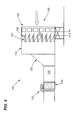
- Figure 1 is a schematic illustrating an environment where an embodiment of the present invention may operate.
- Figure 1 illustrates an inlet system 100 that may be integrated with a gas turbine compressor (not illustrated).
- the following description provides an overview of a typical configuration of an inlet system 100; the present invention may be integrated with other configurations of the inlet system 100, which are not illustrated in the Figures.
- an embodiment of the present invention may be integrated with inlet systems 100 not associated with gas turbines, or other turbomachines.
- the inlet system 100 channels the airstream (represented by the arrow pointed towards the inlet system 100) ingested by the compressor.
- the airstream may derive directly or indirectly from the environment in which the turbomachine operates. Initially, the airstream flows around a weather hood 105, which may prevent weather elements, such as rain, snow, etc, from entering the compressor.
- the weather hood 105 may include a plurality of drift eliminator and/or coalescer pads 107, for reducing the content of liquids within the airstream.
- the airstream may then flow through an inlet filter house 110; which generally removes foreign objects and debris from the airstream.
- the airstream may pass through an air conditioning system 115.
- the airstream may pass through a transition piece 120 and an inlet duct 125; these components may adjust the velocity and pressure of the airstream.
- the airstream may flow through a silencer section 130.
- the airstream may flow through an inlet bleed heat system 135, which generally increases the temperature of the airstream prior to entering the compressor.
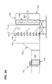
- Figure 2 is a schematic illustrating an air conditioning system 115 in accordance with an embodiment of the present invention.
- Figure 2 illustrates an embodiment of the inlet system 100 and an embodiment of the air conditioning system 115.
- the air conditioning system 115 comprises at least one conditioning module 145 positioned within a housing 140.
- Embodiments of the present invention may significantly reduce the power generation loses and construction costs, by installing the air conditioning system 115 upstream of the inlet system 100. This retrofit may occur while the gas turbine operates and the inlet system 100 receives the airstream.
- the air conditioning system 115 may be bolted onto the front of the inlet system 100, allowing for the airstream continuing to flow through the inlet system 100.
- the housing 140 may enclose a portion or all of the components of the at least one conditioning module 145. As illustrated in Figure 2 , the housing 140 may have a shape similar to the inlet filter house 110, or any other shape allowing for structural integration with the inlet system 100. The integration of the inlet filter house 110 and the housing 140 may allow for a nearly uniform flow of the airstream entering the air conditioning system 115 and then flowing to the inlet filter house 110.
- the housing 140 may be joined to the inlet system 100 via a plurality of connection means, such as, but not limiting of, welding, bolting, other fastening methods, or combinations thereof.
- the housing 140 may created of any material capable of: supporting the at least one conditioning module 145; and allowing for integration with the inlet system 100. This material may be for example, but not limiting of, a metal, an alloy, or other structural materials.
- the air conditioning system 115 of an embodiment of the present invention may install at an operational distance represented as location "X".
- the operational distance may allow for access to the at least one conditioning module 145 within the housing 140.
- the operational distance "X” may aid in maintenance of the at least one conditioning module 145.
- the operational distance "X” may also prevent fluid droplets and/or condensate from the at least one conditioning module 145 from wetting a portion of the filters within the inlet filter house 110.
- the operational distance "X” may also reduce the pressure drop when the air conditioning system 115 is not operation.
- Location X may be from a downstream end of the at least one conditioning module 145 to an upstream end of the weather hood 105.
- the operational distance may comprise a range of from about 1 meter to about 3 meters.
- the at least one conditioning module 145 may have the form of at least one of the following system: a chiller, an evaporative cooler; a spray cooler, or combinations thereof.
- the at least one conditioning module 145 may also include a pre-filter (not illustrating) upstream of the at least one conditioning module 145 to guard against debris and foreign objects.
- the at least one conditioning module 145 may be configured for adjusting the temperature of the airstream.
- the at least one conditioning module 145 may decrease the temperature of the airstream.
- the gas turbine may be operating during a time when the ambient air is above ISO conditions; reducing the power output and efficiency.
- the at least one conditioning module 145 may also increase the temperature of the airstream.
- the gas turbine may be operating during a time when the ambient air conditions may lead to ice formation on the compressor blades.
- this first exemplary embodiment of the present invention may be installed with little disruption to the operation of the gas turbine.
- An operator of the gas turbine may connect the air conditioning system 115 to the front of the inlet system 100.
- the airstream may flow around the and/or through the at least one conditioning module 145.
- the inlet system 100 may not need to be substantially modified to integrate with the air conditioning system 115.
- an operator of the gas turbine may experience significant increases in efficiency and output. For example, but not limiting of, on a large Frame 9 type of gas turbine operating with an ambient airstream temperature of about 90 deg. F and about 50% relative humidity, the air conditioning system 115 may reduce the airstream to about 59 deg. F. This may result in up to a 15% increase power output and up to a 1.0% increase in efficiency.
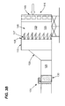
- Figures 3A and 3B are schematics illustrating an air conditioning system 115 in accordance with an alternate embodiment of the present invention. The discussion hereafter will be limited to the differences between this alternate embodiment and the previous embodiment.
- FIG. 3 illustrates the air conditioning system 115 integrated with an inlet system 100 having a bypass 150.
- the bypass 150 may reduce the pressure drop while the air conditioning system 115 is not operating.
- the bypass 150 may increase the overall efficiency and power of the gas turbine.
- the bypass 150 may include at least one damper door 155 positioned between the at least one conditioning module 145 and the inlet filter house 110.
- the at least one damper door 155 may be opened to allow the airstream to flow directly into the inlet system 100. This may allow for a reduction in pressure drop.
- the at least one damper door 155 may slide into a desired position. Alternatively, the at least one damper door 155 may be hinged to allow movement into a desired position.
- the bypass 150 may created out of any material capable of withstanding the operational environments of the inlet system 100 and the air conditioning system 115.
- the air conditioning system 115 of an alternate embodiment of the present invention may install at a bypass distance represented as location "Y".
- the bypass distance may allow for access to the at least one conditioning module 145 within the housing 140.
- Location Y may also reduce the pressure drop when the air conditioning system 115 is not operation.
- Location Y may range from a downstream end of the at least one conditioning module 145 to an upstream end of the weather hood 105.
- the operational distance may comprise a range of from about 1 meter to about 5.5 meters.
Abstract
An embodiment of the present invention provides an air conditioning system (115) located upstream of the inlet system (100) for a gas turbine. The air conditioning system (115) may comprise at least one conditioning module (145) for adjusting the temperature of the airstream. The at least one conditioning module (145) may have a plurality of forms including at least one of the following systems: a chiller, an evaporative cooler; a spray cooler, or combinations thereof The specific form of the at least one conditioning module (145) may be determined in part by the configuration of the gas turbine.
Description
- The present invention relates generally to a turbomachine; and more particularly to a system for increasing the efficiency of a turbomachine.
- Some turbomachines, for example a gas turbine, may generally include, in serial flow arrangement, an inlet system for receiving and channeling an ambient airstream; a compressor which receives and compresses that airstream, a combusting system that mixes a fuel and the compressed airstream, ignites the mixture, and allows for the gaseous by-product to flow to a turbine section; which transfers energy from the gaseous by-product to an output power. Other components of the gas turbine may be used therein.
- The power output of a gas turbine is directly proportional to and limited by the mass flowrate of compressed airstream exiting the compressor. The compressor has a fixed capacity for handling a volumetric flowrate of the airstream for a given rotational speed of the compressor. The mass flowrate of the airstream decreases with an increase in ambient temperature because the air density decreases when air temperature increases. Therefore, the efficiency and power output of the gas turbine decreases below the rated capacity at the ISO conditions with increases in ambient temperature above ISO conditions.
- To generate additional power from an existing gas turbine, an inlet air conditioning system is commonly used. The air conditioning system increases the airstream density by lowering the temperature of the airstream. This increases the mass flowrate of air entering the compressor, resulting in increased efficiency and power output of the gas turbine. An air conditioning system may include, for example, but not limiting of, a chiller, an evaporative cooler, a spray cooler, or combinations thereof, located downstream of an inlet filter house within an inlet system of the gas turbine. Some air conditioning systems, however, add resistance to the airstream entering the compressor. This resistance is defined as a pressure drop in the inlet system and may be measured in inches of water column. Gas turbine efficiency and power output are a direct function of the inlet system pressure drop.
- The higher the inlet system pressure drop, the lower the efficiency and power output of the turbine. Typical pressure drop values across the gas turbine inlet system for power generation varies from about two (2) to about five (5) inches of water column (about five (5) to about 12.7 centimeters of water). This includes the pressure drop across the air conditioning system, which varies from about 0.5 inches to about 1.5 inches of water column (about 1.27 to about 3.8 centimeters of water). Depending on the size of the gas turbine frame, the value of this pressure drop affects the gas turbine output anywhere in the range of about one (1) to about five (5) megawatts at rated ISO conditions. This in turn may affect the turbine efficiency in the range of about 0.01% to about 0.3%. Every point of efficiency and power, however, is essential in the competitive business of power generation or the variety of other uses for mechanical drive gas turbines.
- Operators of existing gas turbines, that do not have an air conditioning system, may desire the additional power output and efficiency increases these systems provide. However, these operators may resist retrofitting the gas turbine for a few reasons including operational downtime and construction costs. Gas turbine operators greatly avoid shutting down the machines because of the associated loss in revenue. Also, the cost of retrofitting an inlet system can be exorbitant.
- One retrofitting approach involves inserting the air conditioning system downstream of the inlet filter house. This approach requires extensive retrofitting, which involves separating the inlet filter house from the transition piece. Next, the inlet filter house is moved forward such that the air conditioning system is inserted between the transition piece and the inlet filter house. Another retrofitting approach involves replacing the existing inlet filter house with a new inlet filter house having an
air conditioning system 115 therein. The downtime, lost revenues, and construction costs prohibit operators from adding an air conditioning system. - For the foregoing reasons, there is a need for an air condition system for retrofitting an operating gas turbine. After installing, the system should minimize the inlet system pressure drop when not in operation. The system components should be installed without a need for extending the overall inlet system. The system should be capable of being installed with minimum disruption to gas turbine operation.
- In an embodiment of the present invention, a system for increasing the efficiency of a turbomachine comprising an inlet system and a compressor, the system comprising: a housing configured to channel an airstream towards the inlet system; wherein the housing is positioned upstream of the inlet system; and at least one conditioning module configured for adjusting the temperature of the airstream; wherein the airstream enters the conditioning module at a first temperature and exits the conditioning module at a second temperature.
- In an alternate embodiment of the present invention, a system for adjusting a temperature of an airstream, the system comprising: an inlet system comprising: an inlet filter house, a transition piece, and an inlet duct; and an air conditioning system comprising: a housing configured to channel an airstream towards the inlet system; wherein the housing is positioned upstream of the inlet system; and at least one conditioning module configured for adjusting the temperature of the airstream; wherein the at least one conditioning module comprises at least one of the following system: a chiller, an evaporative cooler; a spray cooler, or combinations thereof; wherein the airstream enters the conditioning module at a first temperature and exits the conditioning module at a second temperature.
- There follows a detailed description of embodiments of the invention by way of example only with reference to the accompanying drawings, in which:
-
Figure 1 is a schematic illustrating an environment where an embodiment of the present invention may operate; -
Figure 2 is a schematic illustrating an air conditioning system in accordance with an embodiment of the present invention; and -
Figures 3A and3B , collectivelyFigure 3 , are schematics illustrating an air conditioning system in accordance with an alternate embodiment of the present invention. - The following detailed description of preferred embodiments refers to the accompanying drawings, which illustrate specific embodiments of the invention. Other embodiments having different structures and operations do not depart from the scope of the present invention.
- Certain terminology may be used herein for the convenience of the reader only and is not to be taken as a limitation on the scope of the invention. For example, words such as "upper", "lower", "left", "right", "front", "rear", "top", "bottom", "horizontal", "vertical", "upstream", "downstream", "fore", "aft", and the like; merely describe the configuration shown in the Figures. Indeed, the element or elements of an embodiment of the present invention may be oriented in any direction and the terminology, therefore, should be understood as encompassing such variations unless specified otherwise.
- The present invention provides an air conditioning system located upstream of the inlet system for a gas turbine. The air conditioning system may comprise at least one conditioning module for adjusting the temperature of the airstream. The at least one conditioning module may have a plurality of forms including at least one of the following systems: a chiller, an evaporative cooler; a spray cooler, or combinations thereof. The specific form of the at least one conditioning module may be determined in part the configuration of the gas turbine.
- In an embodiment of the present invention, the air conditioning system may decrease the temperature of the airstream entering the inlet system of the gas turbine to increase the efficiency and power output. Alternatively, the air conditioning system may increase the temperature of the airstream entering the inlet system of the gas turbine to reduce the possibly of icing on the compressor blades.
- In an alternate embodiment of the present invention, the air conditioning system may be integrated with a bypass. The bypass may reduce the pressure drop derived from a non-operating air conditioning system.
- Referring now to the Figures, where the various numbers represent like elements throughout the several views,
Figure 1 is a schematic illustrating an environment where an embodiment of the present invention may operate.Figure 1 illustrates aninlet system 100 that may be integrated with a gas turbine compressor (not illustrated). The following description provides an overview of a typical configuration of aninlet system 100; the present invention may be integrated with other configurations of theinlet system 100, which are not illustrated in the Figures. Furthermore, an embodiment of the present invention may be integrated withinlet systems 100 not associated with gas turbines, or other turbomachines. - The
inlet system 100 channels the airstream (represented by the arrow pointed towards the inlet system 100) ingested by the compressor. The airstream may derive directly or indirectly from the environment in which the turbomachine operates. Initially, the airstream flows around aweather hood 105, which may prevent weather elements, such as rain, snow, etc, from entering the compressor. Theweather hood 105 may include a plurality of drift eliminator and/orcoalescer pads 107, for reducing the content of liquids within the airstream. The airstream may then flow through aninlet filter house 110; which generally removes foreign objects and debris from the airstream. Next, the airstream may pass through anair conditioning system 115. Next, the airstream may pass through atransition piece 120 and aninlet duct 125; these components may adjust the velocity and pressure of the airstream. Next, the airstream may flow through asilencer section 130. Next, the airstream may flow through an inletbleed heat system 135, which generally increases the temperature of the airstream prior to entering the compressor. -
Figure 2 is a schematic illustrating anair conditioning system 115 in accordance with an embodiment of the present invention.Figure 2 illustrates an embodiment of theinlet system 100 and an embodiment of theair conditioning system 115. In this embodiment of the present invention theair conditioning system 115 comprises at least oneconditioning module 145 positioned within ahousing 140. - As discussed, operators may refrain from retrofitting a gas turbine with an
air conditioning system 115 because of the lose in power generation and construction costs. Embodiments of the present invention may significantly reduce the power generation loses and construction costs, by installing theair conditioning system 115 upstream of theinlet system 100. This retrofit may occur while the gas turbine operates and theinlet system 100 receives the airstream. In an embodiment of the present invention, theair conditioning system 115 may be bolted onto the front of theinlet system 100, allowing for the airstream continuing to flow through theinlet system 100. - The
housing 140 may enclose a portion or all of the components of the at least oneconditioning module 145. As illustrated inFigure 2 , thehousing 140 may have a shape similar to theinlet filter house 110, or any other shape allowing for structural integration with theinlet system 100. The integration of theinlet filter house 110 and thehousing 140 may allow for a nearly uniform flow of the airstream entering theair conditioning system 115 and then flowing to theinlet filter house 110. Thehousing 140 may be joined to theinlet system 100 via a plurality of connection means, such as, but not limiting of, welding, bolting, other fastening methods, or combinations thereof. Thehousing 140 may created of any material capable of: supporting the at least oneconditioning module 145; and allowing for integration with theinlet system 100. This material may be for example, but not limiting of, a metal, an alloy, or other structural materials. - As illustrated in
Figure 2 , theair conditioning system 115 of an embodiment of the present invention may install at an operational distance represented as location "X". The operational distance may allow for access to the at least oneconditioning module 145 within thehousing 140. The operational distance "X" may aid in maintenance of the at least oneconditioning module 145. The operational distance "X" may also prevent fluid droplets and/or condensate from the at least oneconditioning module 145 from wetting a portion of the filters within theinlet filter house 110. The operational distance "X" may also reduce the pressure drop when theair conditioning system 115 is not operation. Location X may be from a downstream end of the at least oneconditioning module 145 to an upstream end of theweather hood 105. The operational distance may comprise a range of from about 1 meter to about 3 meters. - The at least one
conditioning module 145 may have the form of at least one of the following system: a chiller, an evaporative cooler; a spray cooler, or combinations thereof. The at least oneconditioning module 145 may also include a pre-filter (not illustrating) upstream of the at least oneconditioning module 145 to guard against debris and foreign objects. The at least oneconditioning module 145 may be configured for adjusting the temperature of the airstream. The at least oneconditioning module 145 may decrease the temperature of the airstream. Here, the gas turbine may be operating during a time when the ambient air is above ISO conditions; reducing the power output and efficiency. The at least oneconditioning module 145 may also increase the temperature of the airstream. Here, the gas turbine may be operating during a time when the ambient air conditions may lead to ice formation on the compressor blades. - In use, this first exemplary embodiment of the present invention may be installed with little disruption to the operation of the gas turbine. An operator of the gas turbine may connect the
air conditioning system 115 to the front of theinlet system 100. During the installation the airstream may flow around the and/or through the at least oneconditioning module 145. Moreover, during the installation theinlet system 100 may not need to be substantially modified to integrate with theair conditioning system 115. After installation, an operator of the gas turbine may experience significant increases in efficiency and output. For example, but not limiting of, on a large Frame 9 type of gas turbine operating with an ambient airstream temperature of about 90 deg. F and about 50% relative humidity, theair conditioning system 115 may reduce the airstream to about 59 deg. F. This may result in up to a 15% increase power output and up to a 1.0% increase in efficiency. -
Figures 3A and3B , collectivelyFigure 3 , are schematics illustrating anair conditioning system 115 in accordance with an alternate embodiment of the present invention. The discussion hereafter will be limited to the differences between this alternate embodiment and the previous embodiment. -
Figure 3 illustrates theair conditioning system 115 integrated with aninlet system 100 having abypass 150. Thebypass 150 may reduce the pressure drop while theair conditioning system 115 is not operating. Thebypass 150 may increase the overall efficiency and power of the gas turbine. Thebypass 150 may include at least onedamper door 155 positioned between the at least oneconditioning module 145 and theinlet filter house 110. When theair conditioning system 115 is not operating, the at least onedamper door 155 may be opened to allow the airstream to flow directly into theinlet system 100. This may allow for a reduction in pressure drop. The at least onedamper door 155 may slide into a desired position. Alternatively, the at least onedamper door 155 may be hinged to allow movement into a desired position. Thebypass 150 may created out of any material capable of withstanding the operational environments of theinlet system 100 and theair conditioning system 115. - As illustrated in
Figure 3 , theair conditioning system 115 of an alternate embodiment of the present invention may install at a bypass distance represented as location "Y". The bypass distance may allow for access to the at least oneconditioning module 145 within thehousing 140. Location Y may also reduce the pressure drop when theair conditioning system 115 is not operation. Location Y may range from a downstream end of the at least oneconditioning module 145 to an upstream end of theweather hood 105. The operational distance may comprise a range of from about 1 meter to about 5.5 meters. - The terminology used herein is for the purpose of describing particular embodiments only and is not intended to be limiting of the invention. As used herein, the singular forms "a", "an" and "the" are intended to include the plural forms as well, unless the context clearly indicates otherwise. It will be further understood that the terms "comprises" and/or "comprising," when used in this specification, specify the presence of stated features, integers, steps, operations, elements, and/or components, but do not preclude the presence or addition of one or more other features, integers, steps, operations, elements, components, and/or groups thereof.
- Although the present invention has been shown and described in considerable detail with respect to only a few exemplary embodiments thereof, it should be understood by those skilled in the art that we do not intend to limit the invention to the embodiments since various modifications, omissions and additions may be made to the disclosed embodiments without materially departing from the novel teachings and advantages of the invention, particularly in light of the foregoing teachings. Accordingly, we intend to cover all such modifications, omission, additions and equivalents as may be included within the spirit and scope of the invention as defined by the following claims.
Claims (15)
- A system for increasing the efficiency of a turbomachine comprising an inlet system (100) and a compressor, the system comprising an air conditioning system (115), wherein the air conditioning system (115) comprises:a housing (140) configured to channel an airstream towards the inlet system (100); wherein the housing (140) is positioned upstream of the inlet system (100); andat least one conditioning module (145) configured for adjusting the temperature of the airstream;
wherein the airstream enters the conditioning module (145) at a first temperature and exits the conditioning module (145) at a second temperature. - The system of claim 1 further comprising a bypass (150) for allowing the airstream to flow around the at least one conditioning module (145); wherein portions of the bypass (150) are positioned within the housing (140).
- The system of claim 2, wherein the bypass (150) comprises at least one damper door (155).
- The system of claim 3, wherein the at least one damper door (155) is closed when the at least one conditioning module (145) is operating.
- The system of any of the preceding claims, wherein the at least one conditioning module (145) decreases a temperature of the airstream.
- The system of any of the preceding claims, wherein the at least one conditioning module (145) increases a temperature of the airstream.
- The system of any of the preceding claims, wherein the air conditioning system (115) is located at an operational distance that allows for access to the at least one conditioning module (145).
- The system of claim 7, wherein the operational distance comprises a range of from about 1 meter to about 3 meters.
- The system of claim 2, wherein the air conditioning system (115) is located at a bypass distance that reduces a pressure drop between the at least one conditioning module (145) and the inlet system (100).
- The system of claim 9, wherein the bypass distance comprises a range of from about 1 meter to about 5.5 meters.
- A system for adjusting a temperature of an airstream, the system comprising:an inlet system comprising:an inlet filter house,a transition piece, andan inlet duct; andan air conditioning system comprising:wherein the airstream enters the conditioning module at a first temperature and exits the conditioning module at a second temperature.a housing configured to channel an airstream towards the inlet system; wherein the housing is positioned upstream of the inlet system; andat least one conditioning module configured for adjusting the temperature of the airstream; wherein the at least one conditioning module comprises at least one of the following system: a chiller, an evaporative cooler; a spray cooler, or combinations thereof;
- The system of claim 11 further comprising a bypass, wherein in the bypass allows the airstream to flow around the at least one conditioning module; wherein components of the bypass are positioned within the housing.
- The system of claim 12, wherein the bypass comprises at least one damper door, wherein the at least one damper door is nearly closed when the at least one conditioning module is operating.
- The system of any of claims 11 to 13, wherein the at least one conditioning module decreases a temperature of the airstream from the first temperature to the second temperature.
- The system of any of claims 11 to 14, wherein the at least one conditioning module increases a temperature of the airstream from the first temperature to the second temperature.
Applications Claiming Priority (1)
| Application Number | Priority Date | Filing Date | Title |
|---|---|---|---|
| US12/192,584 US7963095B2 (en) | 2006-06-21 | 2008-08-15 | Inlet air conditioning system |
Publications (1)
| Publication Number | Publication Date |
|---|---|
| EP2154351A2 true EP2154351A2 (en) | 2010-02-17 |
Family
ID=40951580
Family Applications (1)
| Application Number | Title | Priority Date | Filing Date |
|---|---|---|---|
| EP09167380A Withdrawn EP2154351A2 (en) | 2008-08-15 | 2009-08-06 | Inlet air conditioning system for a turbomachine |
Country Status (3)
| Country | Link |
|---|---|
| US (1) | US7963095B2 (en) |
| EP (1) | EP2154351A2 (en) |
| JP (1) | JP2010043645A (en) |
Cited By (2)
| Publication number | Priority date | Publication date | Assignee | Title |
|---|---|---|---|---|
| WO2015066837A1 (en) * | 2013-11-05 | 2015-05-14 | General Electric Company | Gas turbine inlet air conditioning coil system |
| US9546572B2 (en) | 2013-09-24 | 2017-01-17 | General Electric Company | Gas turbine casing load sharing mechanism |
Families Citing this family (24)
| Publication number | Priority date | Publication date | Assignee | Title |
|---|---|---|---|---|
| EP2314883A1 (en) * | 2009-10-20 | 2011-04-27 | Alstom Technology Ltd | Device for feeding air to a compressor of a gas turbine |
| AU2011215608B2 (en) * | 2010-02-15 | 2015-09-03 | Donaldson Company, Inc. | Coil arrangements for air intake system for gas turbine and methods |
| US8702372B2 (en) * | 2010-05-03 | 2014-04-22 | Bha Altair, Llc | System and method for adjusting compressor inlet fluid temperature |
| US9097182B2 (en) | 2010-08-05 | 2015-08-04 | General Electric Company | Thermal control system for fault detection and mitigation within a power generation system |
| US9019108B2 (en) | 2010-08-05 | 2015-04-28 | General Electric Company | Thermal measurement system for fault detection within a power generation system |
| US8349045B2 (en) | 2011-02-11 | 2013-01-08 | General Electric Company | Turbine inlet air filter system |
| US8349043B2 (en) | 2011-02-11 | 2013-01-08 | General Electric Company | Turbine inlet air system |
| US8505309B2 (en) | 2011-06-14 | 2013-08-13 | General Electric Company | Systems and methods for improving the efficiency of a combined cycle power plant |
| US8715384B2 (en) | 2011-06-23 | 2014-05-06 | General Electric Company | Inlet air pulse filtration system |
| US8465573B2 (en) | 2011-10-05 | 2013-06-18 | General Electric Company | System and method for conditioning air flow to a gas turbine |
| US20130186117A1 (en) * | 2012-01-20 | 2013-07-25 | General Electric Company | System and method to process inlet air |
| US20130193127A1 (en) * | 2012-01-26 | 2013-08-01 | General Electric Company | Combustion turbine inlet anti-icing resistive heating system |
| US20140027097A1 (en) * | 2012-07-30 | 2014-01-30 | Ian Alexandre Araujo De Barros | Heat Exchanger for an Intercooler and Water Extraction Apparatus |
| US9719423B2 (en) | 2012-09-04 | 2017-08-01 | General Electric Company | Inlet air chilling system with humidity control and energy recovery |
| US9897003B2 (en) * | 2012-10-01 | 2018-02-20 | General Electric Company | Apparatus and method of operating a turbine assembly |
| US20140123623A1 (en) * | 2012-11-08 | 2014-05-08 | General Electric Company | Gas turbomachine system including an inlet chiller condensate recovery system |
| US20140202186A1 (en) * | 2013-01-18 | 2014-07-24 | Braden Manufacturing, Llc | Zoned Evaporative Cooling Media for Air Intake House of Gas Turbine |
| US9665077B2 (en) * | 2013-12-18 | 2017-05-30 | General Electric Company | Gas turbine firing temperature control system and method |
| CN103967620B (en) * | 2014-05-08 | 2016-04-06 | 中国联合工程公司 | A kind of air inlet rectifying device for large-scale gas turbine |
| US10247096B2 (en) * | 2017-02-22 | 2019-04-02 | S&T Mfg. Co. | Modular gas turbine inlet cooling systems |
| CN107269394B (en) * | 2017-06-20 | 2024-01-19 | 江苏人和环保设备有限公司 | Filter for gas turbine inlet |
| US10947900B2 (en) | 2018-10-26 | 2021-03-16 | General Electric Company | Inlet air heating systems for combined cycle power plants |
| US11828230B2 (en) * | 2021-10-04 | 2023-11-28 | General Electric Company | System and method for mitigating particulate intrusion to an air intake system of a gas turbine system with intrusion protective coatings tailored to locale of operation |
| CN115228221B (en) * | 2022-07-15 | 2023-04-21 | 武汉新烽光电股份有限公司 | Pretreatment cabinet with multistage filtering structure |
Family Cites Families (5)
| Publication number | Priority date | Publication date | Assignee | Title |
|---|---|---|---|---|
| JP2899247B2 (en) * | 1996-05-28 | 1999-06-02 | 川崎重工業株式会社 | Gas turbine inlet heating and cooling system |
| US6769258B2 (en) * | 1999-08-06 | 2004-08-03 | Tom L. Pierson | System for staged chilling of inlet air for gas turbines |
| US7007484B2 (en) | 2003-06-06 | 2006-03-07 | General Electric Company | Methods and apparatus for operating gas turbine engines |
| JP4532224B2 (en) * | 2004-07-22 | 2010-08-25 | 日本無機株式会社 | Gas turbine intake filter unit |
| US7648564B2 (en) * | 2006-06-21 | 2010-01-19 | General Electric Company | Air bypass system for gas turbine inlet |
-
2008
- 2008-08-15 US US12/192,584 patent/US7963095B2/en not_active Expired - Fee Related
-
2009
- 2009-08-06 EP EP09167380A patent/EP2154351A2/en not_active Withdrawn
- 2009-08-11 JP JP2009186208A patent/JP2010043645A/en active Pending
Cited By (2)
| Publication number | Priority date | Publication date | Assignee | Title |
|---|---|---|---|---|
| US9546572B2 (en) | 2013-09-24 | 2017-01-17 | General Electric Company | Gas turbine casing load sharing mechanism |
| WO2015066837A1 (en) * | 2013-11-05 | 2015-05-14 | General Electric Company | Gas turbine inlet air conditioning coil system |
Also Published As
| Publication number | Publication date |
|---|---|
| US20080298957A1 (en) | 2008-12-04 |
| JP2010043645A (en) | 2010-02-25 |
| US7963095B2 (en) | 2011-06-21 |
Similar Documents
| Publication | Publication Date | Title |
|---|---|---|
| EP2154351A2 (en) | Inlet air conditioning system for a turbomachine | |
| EP2578841A2 (en) | System and method for conditioning air flow to a gas turbine | |
| AU2009227834B2 (en) | A system and method for changing the efficiency of a combustion turbine | |
| US8967958B2 (en) | Integration of an air-liquid heat exchanger on an engine | |
| EP0542909B1 (en) | Environmental control system condensing cycle | |
| US7648564B2 (en) | Air bypass system for gas turbine inlet | |
| US9719423B2 (en) | Inlet air chilling system with humidity control and energy recovery | |
| US20110247313A1 (en) | System for heating an airstream by recirculating waste heat of a turbomachine | |
| US8257017B2 (en) | Method and device for cooling a component of a turbine | |
| EP2604807A2 (en) | System and method for active clearance control | |
| US20020182062A1 (en) | Aircraft engine air filter and method | |
| CN101687552B (en) | For the air intake arrangement of the vehicle particularly aircraft | |
| CN107120146B (en) | Active HPC clearance control | |
| CN104420999A (en) | Systems and methods for de-icing a gas turbine engine inlet screen and dehumidifying inlet air filters | |
| US10245540B2 (en) | Inertial particle separator for engine inlet | |
| US8322981B2 (en) | Aircraft fluid diversion inlet louver | |
| RU2344302C2 (en) | Complex air cleaning device for cleaning of gas turbine plant cycle air | |
| US9347455B2 (en) | Ejector assembly | |
| US20150114006A1 (en) | Aircraft engine strut assembly and methods of assembling the same | |
| EP3392484A1 (en) | System and method for regulating flow in turbomachines | |
| KR101373498B1 (en) | Electric power generation plant | |
| EP2314883A1 (en) | Device for feeding air to a compressor of a gas turbine | |
| CN110382825B (en) | Method and system for ice tolerant vent removal | |
| US11846231B2 (en) | System and method for preventing icing in the combustion inlet air path of a gas turbine system | |
| Dickson | Problems associated with cold weather operation of gas turbines |
Legal Events
| Date | Code | Title | Description |
|---|---|---|---|
| PUAI | Public reference made under article 153(3) epc to a published international application that has entered the european phase |
Free format text: ORIGINAL CODE: 0009012 |
|
| AK | Designated contracting states |
Kind code of ref document: A2 Designated state(s): AT BE BG CH CY CZ DE DK EE ES FI FR GB GR HR HU IE IS IT LI LT LU LV MC MK MT NL NO PL PT RO SE SI SK SM TR |
|
| STAA | Information on the status of an ep patent application or granted ep patent |
Free format text: STATUS: THE APPLICATION IS DEEMED TO BE WITHDRAWN |
|
| 18D | Application deemed to be withdrawn |
Effective date: 20140301 |