EP2154337A2 - Schmiermittelschaufel - Google Patents
Schmiermittelschaufel Download PDFInfo
- Publication number
- EP2154337A2 EP2154337A2 EP09251883A EP09251883A EP2154337A2 EP 2154337 A2 EP2154337 A2 EP 2154337A2 EP 09251883 A EP09251883 A EP 09251883A EP 09251883 A EP09251883 A EP 09251883A EP 2154337 A2 EP2154337 A2 EP 2154337A2
- Authority
- EP
- European Patent Office
- Prior art keywords
- lubricant
- central axis
- scoop
- radially
- axis
- Prior art date
- Legal status (The legal status is an assumption and is not a legal conclusion. Google has not performed a legal analysis and makes no representation as to the accuracy of the status listed.)
- Granted
Links
Images


Classifications
-
- F—MECHANICAL ENGINEERING; LIGHTING; HEATING; WEAPONS; BLASTING
- F01—MACHINES OR ENGINES IN GENERAL; ENGINE PLANTS IN GENERAL; STEAM ENGINES
- F01D—NON-POSITIVE DISPLACEMENT MACHINES OR ENGINES, e.g. STEAM TURBINES
- F01D25/00—Component parts, details, or accessories, not provided for in, or of interest apart from, other groups
- F01D25/18—Lubricating arrangements
-
- F—MECHANICAL ENGINEERING; LIGHTING; HEATING; WEAPONS; BLASTING
- F01—MACHINES OR ENGINES IN GENERAL; ENGINE PLANTS IN GENERAL; STEAM ENGINES
- F01D—NON-POSITIVE DISPLACEMENT MACHINES OR ENGINES, e.g. STEAM TURBINES
- F01D25/00—Component parts, details, or accessories, not provided for in, or of interest apart from, other groups
- F01D25/16—Arrangement of bearings; Supporting or mounting bearings in casings
-
- F—MECHANICAL ENGINEERING; LIGHTING; HEATING; WEAPONS; BLASTING
- F16—ENGINEERING ELEMENTS AND UNITS; GENERAL MEASURES FOR PRODUCING AND MAINTAINING EFFECTIVE FUNCTIONING OF MACHINES OR INSTALLATIONS; THERMAL INSULATION IN GENERAL
- F16C—SHAFTS; FLEXIBLE SHAFTS; ELEMENTS OR CRANKSHAFT MECHANISMS; ROTARY BODIES OTHER THAN GEARING ELEMENTS; BEARINGS
- F16C33/00—Parts of bearings; Special methods for making bearings or parts thereof
- F16C33/30—Parts of ball or roller bearings
- F16C33/66—Special parts or details in view of lubrication
- F16C33/6637—Special parts or details in view of lubrication with liquid lubricant
- F16C33/6659—Details of supply of the liquid to the bearing, e.g. passages or nozzles
- F16C33/6677—Details of supply of the liquid to the bearing, e.g. passages or nozzles from radial inside, e.g. via a passage through the shaft and/or inner ring
-
- F—MECHANICAL ENGINEERING; LIGHTING; HEATING; WEAPONS; BLASTING
- F16—ENGINEERING ELEMENTS AND UNITS; GENERAL MEASURES FOR PRODUCING AND MAINTAINING EFFECTIVE FUNCTIONING OF MACHINES OR INSTALLATIONS; THERMAL INSULATION IN GENERAL
- F16N—LUBRICATING
- F16N7/00—Arrangements for supplying oil or unspecified lubricant from a stationary reservoir or the equivalent in or on the machine or member to be lubricated
- F16N7/14—Arrangements for supplying oil or unspecified lubricant from a stationary reservoir or the equivalent in or on the machine or member to be lubricated the lubricant being conveyed from the reservoir by mechanical means
- F16N7/16—Arrangements for supplying oil or unspecified lubricant from a stationary reservoir or the equivalent in or on the machine or member to be lubricated the lubricant being conveyed from the reservoir by mechanical means the oil being carried up by a lifting device
-
- F—MECHANICAL ENGINEERING; LIGHTING; HEATING; WEAPONS; BLASTING
- F16—ENGINEERING ELEMENTS AND UNITS; GENERAL MEASURES FOR PRODUCING AND MAINTAINING EFFECTIVE FUNCTIONING OF MACHINES OR INSTALLATIONS; THERMAL INSULATION IN GENERAL
- F16N—LUBRICATING
- F16N7/00—Arrangements for supplying oil or unspecified lubricant from a stationary reservoir or the equivalent in or on the machine or member to be lubricated
- F16N7/30—Arrangements for supplying oil or unspecified lubricant from a stationary reservoir or the equivalent in or on the machine or member to be lubricated the oil being fed or carried along by another fluid
- F16N7/32—Mist lubrication
-
- F—MECHANICAL ENGINEERING; LIGHTING; HEATING; WEAPONS; BLASTING
- F05—INDEXING SCHEMES RELATING TO ENGINES OR PUMPS IN VARIOUS SUBCLASSES OF CLASSES F01-F04
- F05D—INDEXING SCHEME FOR ASPECTS RELATING TO NON-POSITIVE-DISPLACEMENT MACHINES OR ENGINES, GAS-TURBINES OR JET-PROPULSION PLANTS
- F05D2260/00—Function
- F05D2260/60—Fluid transfer
-
- F—MECHANICAL ENGINEERING; LIGHTING; HEATING; WEAPONS; BLASTING
- F16—ENGINEERING ELEMENTS AND UNITS; GENERAL MEASURES FOR PRODUCING AND MAINTAINING EFFECTIVE FUNCTIONING OF MACHINES OR INSTALLATIONS; THERMAL INSULATION IN GENERAL
- F16C—SHAFTS; FLEXIBLE SHAFTS; ELEMENTS OR CRANKSHAFT MECHANISMS; ROTARY BODIES OTHER THAN GEARING ELEMENTS; BEARINGS
- F16C19/00—Bearings with rolling contact, for exclusively rotary movement
- F16C19/02—Bearings with rolling contact, for exclusively rotary movement with bearing balls essentially of the same size in one or more circular rows
- F16C19/04—Bearings with rolling contact, for exclusively rotary movement with bearing balls essentially of the same size in one or more circular rows for radial load mainly
- F16C19/06—Bearings with rolling contact, for exclusively rotary movement with bearing balls essentially of the same size in one or more circular rows for radial load mainly with a single row or balls
-
- F—MECHANICAL ENGINEERING; LIGHTING; HEATING; WEAPONS; BLASTING
- F16—ENGINEERING ELEMENTS AND UNITS; GENERAL MEASURES FOR PRODUCING AND MAINTAINING EFFECTIVE FUNCTIONING OF MACHINES OR INSTALLATIONS; THERMAL INSULATION IN GENERAL
- F16C—SHAFTS; FLEXIBLE SHAFTS; ELEMENTS OR CRANKSHAFT MECHANISMS; ROTARY BODIES OTHER THAN GEARING ELEMENTS; BEARINGS
- F16C2360/00—Engines or pumps
- F16C2360/23—Gas turbine engines
-
- F—MECHANICAL ENGINEERING; LIGHTING; HEATING; WEAPONS; BLASTING
- F16—ENGINEERING ELEMENTS AND UNITS; GENERAL MEASURES FOR PRODUCING AND MAINTAINING EFFECTIVE FUNCTIONING OF MACHINES OR INSTALLATIONS; THERMAL INSULATION IN GENERAL
- F16N—LUBRICATING
- F16N2210/00—Applications
- F16N2210/02—Turbines
-
- F—MECHANICAL ENGINEERING; LIGHTING; HEATING; WEAPONS; BLASTING
- F16—ENGINEERING ELEMENTS AND UNITS; GENERAL MEASURES FOR PRODUCING AND MAINTAINING EFFECTIVE FUNCTIONING OF MACHINES OR INSTALLATIONS; THERMAL INSULATION IN GENERAL
- F16N—LUBRICATING
- F16N2210/00—Applications
- F16N2210/14—Bearings
Definitions
- the invention relates to a structure for receiving a spray of lubricant and for directing the received lubricant axially and radially relative to an axis of rotation.
- a lubricant scoop is used to direct lubricant axially along a rotating shaft and also radially relative to the axis of rotation.
- Lubricant scoops are useful when other structures adjacent to the shaft render the component requiring lubrication inaccessible.
- the lubricant scoop receives a radially-directed stream of lubricant from a jet or spray orifice and redirects the lubricant axially.
- the invention is a lubricant scoop.
- the lubricant scoop comprises an annular body encircling a central axis. The annular body is operable to rotate about the central axis in a first direction.
- the lubricant scoop also comprises a plurality of lubricant passageways defined in the annular body. Each of the plurality of passageways extends radially inward toward the central axis from respective entry ports to respective exit ports.
- the lubricant scoop also comprises an entry plenum defined in the annular body. The entry plenum is upstream of and fluidly communicates with each of the plurality of passageways. The entry plenum has an upstream opening operable to receive lubricant from a lubricant spray nozzle.
- Figure 1 is a perspective view of a lubricant scoop according to an exemplary embodiment of the invention
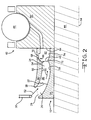
- Figure 2 is a cross-sectional view taken along an axis of rotation of a shaft in a turbine engine incorporating the exemplary embodiment of the invention.
- Figure 3 is a cut-away view of the exemplary embodiment of the invention.
- Lubricant sprayed through a lubricant nozzle possesses momentum in the direction of spray.
- Momentum is a quantity relating to the motion of a body, such as a droplet of lubricant, and is equal to the product of the mass of the body and its velocity.
- Velocity is a quantity defined as the time rate of change of the position of the body in a specified direction. Velocity thus changes when the direction of movement of the body changes, unless some other force is applied to the body. Furthermore, velocity changes result in changes to the momentum of the body.
- the exemplary embodiment of the present invention takes advantage of the momentum generated by spraying the lubricant from a lubricant nozzle in order to move the lubricant through a lubricant scoop.
- Advantages provided by the exemplary embodiment of the present invention in a turbine engine are set forth below.
- Alternative embodiments of the invention can be practiced to in different operating environments to realize similar or different benefits. It is noted that the benefits articulated herein may not be realized in all operating environments for all embodiments of the invention. Furthermore, it is noted that the benefits articulated herein are not exhaustive, other benefits may be perceived in the practice of the exemplary embodiment or in the practice of alternative embodiments of the invention.
- the benefits associated with the exemplary embodiment and described herein are not limitations of the broader invention, but rather demonstrate industrial applicability.
- FIG 1 is a perspective view of a lubricant scoop 10 according to an exemplary embodiment of the invention.
- the lubricant scoop 10 comprises an annular body 12 encircling a central axis 14.
- the annular body 12 is operable to rotate about the central axis 14 in a first direction, represented by arrows 16 and 18.
- the lubricant scoop 10 also comprises a plurality of lubricant passageways 20 defined in the annular body 12. Referring now to Figure 2 , each of the plurality of passageways 20 extend radially inward toward the central axis 14 from respective entry ports 22 to respective exit ports 24.
- the lubricant scoop 10 also comprises an entry plenum 26 defined in the annular body 12.
- the entry plenum 26 is upstream of and fluidly communicates with each of the plurality of passageways 20.
- the entry plenum 26 has an upstream opening 28 operable to receive lubricant from a lubricant spray nozzle 30.
- the upstream opening 28 is shown in dashed line in Figure 2
- Figures 1 and 2 show that the exemplary the lubricant scoop 10 can be formed with a first ring 32 centered on the central axis 14.
- the exemplary lubricant scoop 10 can also include a second ring 34 concentric with and spaced radially inward from the first ring 32.
- a plurality of vanes 36 can individually extend radially between the first and second rings 32, 34.
- the plurality of vanes 36 can also extend axially along the central axis 14.
- An individual passageway 20 is defined between two adjacent vanes 36.
- Figure 2 shows a single vane 36 extending between a leading edge 38 and a trailing edge 40.
- An entry port 22 is defined between adjacent leading edges 38 of two vanes 36.
- Figure 2 also shows that the entry plenum 26 can extend radially between the first and second rings 32, 34 and axially along the central axis 14 between the upstream opening 28 and the leading edge 38 of the vane 36.
- the opening 28 is shown in dash line in Figure 2 since it references the plane of the opening into the capture area.
- the exemplary lubricant scoop 10 can be incorporated in a turbine engine.
- the turbine engine can include a shaft 44 operable to rotate about the axis 14 in a first angular direction.
- the first angular direction is the same direction as the first direction represented by arrows 16 and 18. With respect to the perspective of Figure 2 , the first direction implies that the illustrated structures above the axis 14 are coming out of the page.
- the turbine engine can also include a component 46 mounted to the shaft 44.
- the illustrated component 46 is a bearing with a rolling sphere 48 and an inner race 50 mounted to rotate with the shaft 44.
- the component can be a gear, a different configuration of bearing, a seal runner, or any other structure which is to receive lubricant during operation.
- the lubricant scoop 10 can be mounted to rotate with the shaft 44 and be positioned adjacent to the component 46.
- the lubricant scoop 10 can be directly adjacent to the component 46, as shown, or can be spaced from the component 46 in alternative embodiments of the invention.
- the lubricant nozzle 30 can be oriented to direct lubricant in a first rectilinear direction, represented by arrow 52.
- the lubricant nozzle 30 can direct lubricant in the first rectilinear direction represented by arrow 52 across an open space and through the upstream opening 28.
- the first rectilinear direction represented by arrow 52 includes a first directional component along the axis 14 and a second directional component toward the axis 14.
- the upstream opening 28 extends 360 degrees about the central axis 14.
- the exemplary lubricant scoop 10 can thus continuously collect lubricant; no structure blocks lubricant at any point during rotation of the exemplary embodiment of the invention.
- Alternative embodiments of the invention can include a discontinuous upstream opening if operating considerations indicate a discontinuous upstream opening is desirable.
- the upstream opening 28 can be transverse to the central axis 14.
- the dash line representing the upstream opening 28 in Figure 2 if extended, would intersect the axis 14 in the plane of Figure 2 .
- Transverse means non-parallel, either perpendicular or at an angle less then ninety degrees.
- the orientation of the upstream opening 28 and the first rectilinear direction represented by arrow 52 allows the lubricant scoop 10 to receive lubricant possessing momentum in the axial direction.
- the axial momentum of the lubricant generated by spraying is applied to move the lubricant through the lubricant scoop 10.
- the lubricant can collide with one of the surfaces defining the passageway 20, a surface defining the entry plenum 26, or a leading edge 38 of one of the vanes 36.
- Figure 2 shows the first rectilinear direction represented by arrow 52 in a first plane
- Figure 3 shows the first rectilinear direction represented by arrow 52 in a second plane perpendicular to the first plane.
- the view in Figure 3 is of the lubricant scoop 10 with the first ring 32 removed and the second ring 34 laid flat to enhance clarity.
- a first vane 36 is shown relative to the axis 14 of rotation and a second vane 36 is shown for reference.
- Figure 3 shows that the vanes 36 can be airfoil-shaped in radial cross-section, with the leading edge 38 and the trailing edge 40 and a concave surface 54 facing the first angular direction represented by arrow 16.
- the vanes 36 can be generally arcuate in radial cross-section in that the leading edges 38 and the trailing edges 40 of each of the plurality vanes 36 are circumferentially spaced from one another. Again, based on the viewing perspective, the circumference of the second ring 34 extends vertically in Figure 3 .
- the concave surface 54 is a first side surface of an individual passageway 20. At the leading edge 38 or respective entry port 22, the surface 54 can be transverse to the central axis 14. The surface 54 can be shaped at the leading edge 38 such that the first rectilinear direction represented by arrow 52 is tangent to the concave surface 54 at the leading edge 38. Because the vane 36 is continuously moving, the first rectilinear direction represented by arrow 52 is intermittently tangent to the concave surface at the leading edge 38.
- the concave surface 54 can be substantially parallel to the axis 14 of rotation at the trailing edge 40, the line 56 being tangent to the concave surface 54 at the trailing edge 40.
- the lubricant spray received on the concave surface 54 can follow the curvature of the concave surface 54 and be moved along the axis 14, redirected from movement in a partially axial direction to movement in a substantially fully axial direction.
- Lubricant received at the leading edge 38 will experience a less abrupt change of direction than lubricant received on the concave surface 54 aft of the leading edge 38, thereby conserving a maximum amount of momentum.
- all of the lubricant received on the concave surface 54 can be redirected to more axial movement without losing all momentum.
- the portion of lubricant spray not received by the concave surface 54 will contact a radially outer surface 58 of the second ring 34.
- the surface 58 is arcuate and transverse to the first rectilinear direction represented by arrow 52. Similar to the concave surface 54, the surface 58 can be concave and can redirect lubricant to more axial movement.
- the exemplary passageways 20 can narrow both radially and circumferentially along the central axis 14 between the respective entry port 22 and the respective exit port 24.
- the passageways 20 can thus build speed of the lubricant moving along the axis 14 and increase momentum.
- the first ring 32 can include a radially-innermost surface 60 acting as the radially-outermost surface of each passageway 20.
- the surface 60 can be convex to the axis 14 and be defined by a first radius of curvature. Movement of lubricant along the surface 60, from the entry port 22 to the exit port 24, is radially inward and is therefore movement against centrifugal forces. Therefore, the first radius of curvature can be relatively small or gentle.
- the concave surface 54 can define a second radius of curvature more aggressive than the first radius of curvature of the surface 60.
- the second radius of curvature of the surface 54 can be more aggressive than the first radius of curvature of the surface 60.
- the shape of the surface 54 can encourage movement of lubricant toward the exit port 24. The surface 54 falls away in the direction of rotation and therefore lubricant will be induced to follow the surface 54 to the exit port 24.
- the shape of the passageway 20 applies the propensity of the lubricant to move relatively easier along the surface 54 towards moving the lubricant along the surface 60, which is relatively more difficult.
- the cooperation between the two surfaces 54, 60 can thus promote movement of the lubricant toward the axis 14.
- the various radii of curvature discussed herein need not be constant across the various surfaces for practicing the invention. Any of the various surfaces can be comprised of a plurality of discrete portions, each with a different radius of curvature.
- the exemplary embodiment simply offers one way of practicing the invention in which the side surface of the passageway falls circumferentially away from a leading edge at a greater rate than the top surface falls radially downward toward the axis of rotation.
- the exemplary lubricant scoop 10 can also include an exhaust plenum 62 defined in the annular body 12 downstream of and fluidly communicating with each of the plurality of passageways 20.
- the exhaust plenum 62 can include a downstream opening 64 permitting lubricant to escape from the annular body 12.
- the exhaust plenum 62 can also include an annular notch 66 facing the axis 14.
- the notch 66 can extend 360° around the axis and have a first, forward side wall 68 positioned adjacent to the exit ports 24 of the plurality of passageways 20.
- the notch 66 can also include a second, aft side wall 70 opposite the first side wall 68.
- the second side wall 70 can be shorter than the first side wall 68.
- the side wall 68 extends further toward the axis 14 than the side wall 70.
- the exemplary notch 66 can act as a catch basin, collecting lubricant falling radially outward over the edge defined by the intersection between the side wall 68 and the surface 60.
- Lubricant can be collected in the notch 66 to a circumferentially uniform pool height, stabilizing flow. Lubricant can overflow the notch 66 by passing over the aft side wall 70. Thus, the relative sizes of the side walls 68 and 70 can prevent backflow of the lubricant.
- the respective positions of the walls 68, 70 relative to the vanes 36 are shown in phantom line in Figure 3 .
- the exemplary lubricant scoop 10 also provides additional structure to reduce the backflow of lubricant on the surface 58.
- Figure 2 shows the surface 58 extending between the upstream opening 28 and a lip 72.
- the lip 72 is defined between the surface 58 and a radially-innermost surface 74 of the exhaust plenum 62.
- the surface 74 can be convex to the central axis 14 and abut the surface 58 along the axis 14. Lubricant moving along the surface 58 toward the exit port 24 can escape the surface 58 at the lip 72 and be collected in the notch 66.
- the surfaces 58, 74 can have at least one of different radii of curvature and/or different centers of curvature so that the lip 72 is relatively pronounced to encourage lubricant from escaping the surface 58.
- the surface 58 can have a greater radius of curvature than the surface 60 to induce separation of the lubricant from the surface 58.
Landscapes
- Engineering & Computer Science (AREA)
- General Engineering & Computer Science (AREA)
- Mechanical Engineering (AREA)
- Chemical & Material Sciences (AREA)
- Combustion & Propulsion (AREA)
- Oil, Petroleum & Natural Gas (AREA)
- Rolling Contact Bearings (AREA)
- General Details Of Gearings (AREA)
- Food-Manufacturing Devices (AREA)
Applications Claiming Priority (1)
| Application Number | Priority Date | Filing Date | Title |
|---|---|---|---|
| US12/192,294 US8464835B2 (en) | 2008-08-15 | 2008-08-15 | Lubricant scoop |
Publications (3)
| Publication Number | Publication Date |
|---|---|
| EP2154337A2 true EP2154337A2 (de) | 2010-02-17 |
| EP2154337A3 EP2154337A3 (de) | 2011-03-16 |
| EP2154337B1 EP2154337B1 (de) | 2018-12-26 |
Family
ID=41343998
Family Applications (1)
| Application Number | Title | Priority Date | Filing Date |
|---|---|---|---|
| EP09251883.6A Not-in-force EP2154337B1 (de) | 2008-08-15 | 2009-07-27 | Schmiermittelschaufel |
Country Status (2)
| Country | Link |
|---|---|
| US (1) | US8464835B2 (de) |
| EP (1) | EP2154337B1 (de) |
Cited By (3)
| Publication number | Priority date | Publication date | Assignee | Title |
|---|---|---|---|---|
| EP3018303A1 (de) * | 2014-11-06 | 2016-05-11 | Rolls-Royce plc | Ölverteiler |
| EP3693651A1 (de) * | 2019-02-07 | 2020-08-12 | United Technologies Corporation | Ölzufuhrdüse mit ungleichmässigem sprühmuster |
| CN111878237A (zh) * | 2020-07-29 | 2020-11-03 | 中国航发湖南动力机械研究所 | 收油环及环下供油润滑装置 |
Families Citing this family (21)
| Publication number | Priority date | Publication date | Assignee | Title |
|---|---|---|---|---|
| EP2375092B1 (de) * | 2010-04-06 | 2013-03-27 | Siemens Aktiengesellschaft | Schmiersystem für Lager |
| US8308426B2 (en) * | 2010-07-30 | 2012-11-13 | United Technologies Corporation | Shaft assembly for a gas turbine engine |
| US8997937B2 (en) * | 2012-07-25 | 2015-04-07 | Bell Helicopter Textron Inc. | Direct drive rotation device for passively moving fluid |
| US8985277B2 (en) | 2012-07-31 | 2015-03-24 | United Technologies Corporation | Case with integral lubricant scavenge passage |
| US20140241851A1 (en) * | 2013-02-27 | 2014-08-28 | United Technologies Corporation | Axial oil scoop for a gas turbine engine |
| EP3094845B1 (de) * | 2014-01-15 | 2020-04-29 | United Technologies Corporation | Kühlsysteme für gasturbinenmotoren |
| US9726040B2 (en) | 2015-03-27 | 2017-08-08 | Pratt & Whitney Canada Corp. | Fluid delivery system for a gas turbine engine |
| US9797268B2 (en) * | 2015-03-27 | 2017-10-24 | United Technologies Corporation | Oil scoop with integrated sensor |
| US9732630B2 (en) * | 2015-03-27 | 2017-08-15 | United Technologies Corporation | Oil scoop and shaft with axially-oriented hole |
| US9989083B2 (en) | 2015-05-26 | 2018-06-05 | Pratt & Whitney Canada Corp. | Seal and bearing assembly for a gas turbine engine and method of assembling same |
| US10731558B2 (en) * | 2016-02-16 | 2020-08-04 | Rolls-Royce Corporation | Circumferential lubricant scoop |
| US10174629B1 (en) * | 2017-09-11 | 2019-01-08 | United Technologies Corporation | Phonic seal seat |
| US10662812B2 (en) * | 2017-10-20 | 2020-05-26 | United Technologies Corporation | Lubricant scoop |
| DE102018107494A1 (de) * | 2018-03-28 | 2019-10-02 | Rolls-Royce Deutschland Ltd & Co Kg | Planetengetriebevorrichtung mit einer Ölversorgungseinrichtung, Gasturbinentriebwerk mit einer Planetengetriebevorrichtung und Verfahren zum Herstellen einer Schaufelpumpe |
| GB201805180D0 (en) * | 2018-03-29 | 2018-05-16 | Rolls Royce Plc | Oil distribution assembly |
| US10746051B2 (en) * | 2018-09-21 | 2020-08-18 | United Technologies Corporation | Hybrid wet-dry face seal seat |
| US11022174B2 (en) | 2018-09-28 | 2021-06-01 | Rolls-Royce Corporation | Drain arrangement for a squeeze film damper |
| US11486270B2 (en) | 2018-09-28 | 2022-11-01 | Rolls-Royce Corporation | Splined oil catcher |
| US10527098B1 (en) | 2018-09-28 | 2020-01-07 | Rolls-Royce Corporation | Systems and methods of oil distribution for a bearing |
| US11852029B2 (en) | 2020-08-14 | 2023-12-26 | Rtx Corporation | Scoop assembly for rotational equipment |
| CN119021986A (zh) * | 2024-10-21 | 2024-11-26 | 马鞍山易联仓储科技有限公司 | 一种输送设备用自动定量润滑的轴承 |
Family Cites Families (20)
| Publication number | Priority date | Publication date | Assignee | Title |
|---|---|---|---|---|
| DE1030637B (de) | 1954-05-06 | 1958-05-22 | Heidenreich & Harbeck Gmbh | Einrichtung zur Schmierung der Waelzlager einer in einem Getriebekasten angeordneten Welle |
| US2874803A (en) * | 1955-07-26 | 1959-02-24 | United Aircraft Corp | Lubrication means |
| US2878894A (en) | 1955-11-14 | 1959-03-24 | United Aircraft Corp | Lubricating means |
| US3195682A (en) * | 1962-12-21 | 1965-07-20 | Ford Motor Co | Lubricating means for bearings |
| US4013141A (en) * | 1975-10-16 | 1977-03-22 | General Electric Company | Means for lubricating a mechanism disposed within a rotating shaft |
| US4221279A (en) * | 1978-12-11 | 1980-09-09 | Dana Corporation | Centrifugal lubrication system for transmission pocket bearing |
| US4342489A (en) | 1980-10-07 | 1982-08-03 | Teledyne Industries, Inc. | Bearing lubricating injector |
| US4648485A (en) | 1985-10-04 | 1987-03-10 | United Technologies Corporation | Radial scoop construction |
| JPS63231021A (ja) * | 1987-03-17 | 1988-09-27 | Nippon Seiko Kk | 転がり軸受の潤滑装置 |
| DE4041389A1 (de) * | 1990-12-21 | 1992-06-25 | Kugelfischer G Schaefer & Co | Vorrichtung zum entfernen von oel aus ringraeumen |
| US5904427A (en) | 1996-11-04 | 1999-05-18 | Stemco Inc | Unitized wheel hub and bearing assembly with lubricant distributing vanes |
| JP2000249151A (ja) | 1998-12-28 | 2000-09-12 | Nsk Ltd | 転がり軸受の潤滑構造 |
| US6200037B1 (en) | 1999-06-02 | 2001-03-13 | Stemco Inc | Lubricant distributing vanes for unitized wheel hub and bearing assembly |
| JP2001099167A (ja) | 1999-09-28 | 2001-04-10 | Mitsubishi Heavy Ind Ltd | 回転軸の軸受の流体供給構造 |
| US6409464B1 (en) | 2000-06-30 | 2002-06-25 | General Electric Company | Methods and apparatus for supplying oil to bearing assemblies |
| US6682222B2 (en) | 2001-08-22 | 2004-01-27 | General Electric Company | Bi-directional oil scoop for bearing lubrication |
| US6735956B2 (en) * | 2001-10-26 | 2004-05-18 | Pratt & Whitney Canada Corp. | High pressure turbine blade cooling scoop |
| US20060062504A1 (en) * | 2004-09-23 | 2006-03-23 | Wilton Stephen A | Lubricant distribution weir for lubricating moving machine elements |
| CN101581340B (zh) * | 2004-10-08 | 2011-06-08 | Ntn株式会社 | 滚动轴承 |
| US7244096B2 (en) | 2005-05-19 | 2007-07-17 | Honeywell International, Inc. | Curved blade oil scoop |
-
2008
- 2008-08-15 US US12/192,294 patent/US8464835B2/en active Active
-
2009
- 2009-07-27 EP EP09251883.6A patent/EP2154337B1/de not_active Not-in-force
Cited By (5)
| Publication number | Priority date | Publication date | Assignee | Title |
|---|---|---|---|---|
| EP3018303A1 (de) * | 2014-11-06 | 2016-05-11 | Rolls-Royce plc | Ölverteiler |
| US9897005B2 (en) | 2014-11-06 | 2018-02-20 | Rolls-Royce Plc | Oil distributor |
| EP3693651A1 (de) * | 2019-02-07 | 2020-08-12 | United Technologies Corporation | Ölzufuhrdüse mit ungleichmässigem sprühmuster |
| US11230946B2 (en) | 2019-02-07 | 2022-01-25 | Raytheon Technologies Corporation | Non-uniform spray pattern oil delivery nozzle |
| CN111878237A (zh) * | 2020-07-29 | 2020-11-03 | 中国航发湖南动力机械研究所 | 收油环及环下供油润滑装置 |
Also Published As
| Publication number | Publication date |
|---|---|
| US8464835B2 (en) | 2013-06-18 |
| EP2154337A3 (de) | 2011-03-16 |
| US20100038173A1 (en) | 2010-02-18 |
| EP2154337B1 (de) | 2018-12-26 |
Similar Documents
| Publication | Publication Date | Title |
|---|---|---|
| US8464835B2 (en) | Lubricant scoop | |
| EP3196426B1 (de) | Schmierstoffrücklaufsystem | |
| EP2766622B1 (de) | Dynamisch geschmiertes lager | |
| US8517612B2 (en) | Bearing oiling system | |
| US7244096B2 (en) | Curved blade oil scoop | |
| EP2766621B1 (de) | Dynamisch geschmiertes lager und verfahren zur dynamischen schmierung eines lagers | |
| EP3214329B1 (de) | Schmiermittelfanganordnung mit schaufeln an einer sich zwischen einer welle und einem wälzlager einer gasturbine erstreckenden hülse | |
| EP2414654B1 (de) | Turbomaschine mit wellendichtungsanordnung | |
| US7232258B2 (en) | Passive bearing clearance control using a pre-swirler | |
| US6640933B2 (en) | Lubrication system for a bearing | |
| EP3699447B1 (de) | Lager zur verwendung in hochgeschwindigkeitsanwendungen | |
| US8240434B2 (en) | Flow control arrangement | |
| JP2014025525A (ja) | オイルエア潤滑式転がり軸受装置 | |
| EP3683465B1 (de) | Lager zur verwendung in einer hochgeschwindigkeitsanwendung | |
| JP5024114B2 (ja) | ターボチャージャ用軸受装置 | |
| JP2006090461A (ja) | 転がり軸受 | |
| US20240318688A1 (en) | Lubricant draining bearing assemblies |
Legal Events
| Date | Code | Title | Description |
|---|---|---|---|
| PUAI | Public reference made under article 153(3) epc to a published international application that has entered the european phase |
Free format text: ORIGINAL CODE: 0009012 |
|
| AK | Designated contracting states |
Kind code of ref document: A2 Designated state(s): AT BE BG CH CY CZ DE DK EE ES FI FR GB GR HR HU IE IS IT LI LT LU LV MC MK MT NL NO PL PT RO SE SI SK SM TR |
|
| AX | Request for extension of the european patent |
Extension state: AL BA RS |
|
| PUAL | Search report despatched |
Free format text: ORIGINAL CODE: 0009013 |
|
| AK | Designated contracting states |
Kind code of ref document: A3 Designated state(s): AT BE BG CH CY CZ DE DK EE ES FI FR GB GR HR HU IE IS IT LI LT LU LV MC MK MT NL NO PL PT RO SE SI SK SM TR |
|
| AX | Request for extension of the european patent |
Extension state: AL BA RS |
|
| RIC1 | Information provided on ipc code assigned before grant |
Ipc: F16N 7/32 20060101ALI20110210BHEP Ipc: F16C 33/66 20060101ALI20110210BHEP Ipc: F01D 25/18 20060101AFI20091130BHEP Ipc: F16H 57/04 20100101ALI20110210BHEP |
|
| 17P | Request for examination filed |
Effective date: 20110916 |
|
| 17Q | First examination report despatched |
Effective date: 20130304 |
|
| 17Q | First examination report despatched |
Effective date: 20130315 |
|
| STAA | Information on the status of an ep patent application or granted ep patent |
Free format text: STATUS: EXAMINATION IS IN PROGRESS |
|
| GRAP | Despatch of communication of intention to grant a patent |
Free format text: ORIGINAL CODE: EPIDOSNIGR1 |
|
| STAA | Information on the status of an ep patent application or granted ep patent |
Free format text: STATUS: GRANT OF PATENT IS INTENDED |
|
| INTG | Intention to grant announced |
Effective date: 20180912 |
|
| GRAS | Grant fee paid |
Free format text: ORIGINAL CODE: EPIDOSNIGR3 |
|
| GRAA | (expected) grant |
Free format text: ORIGINAL CODE: 0009210 |
|
| STAA | Information on the status of an ep patent application or granted ep patent |
Free format text: STATUS: THE PATENT HAS BEEN GRANTED |
|
| AK | Designated contracting states |
Kind code of ref document: B1 Designated state(s): AT BE BG CH CY CZ DE DK EE ES FI FR GB GR HR HU IE IS IT LI LT LU LV MC MK MT NL NO PL PT RO SE SI SK SM TR |
|
| REG | Reference to a national code |
Ref country code: GB Ref legal event code: FG4D |
|
| REG | Reference to a national code |
Ref country code: CH Ref legal event code: EP |
|
| REG | Reference to a national code |
Ref country code: DE Ref legal event code: R096 Ref document number: 602009056373 Country of ref document: DE |
|
| REG | Reference to a national code |
Ref country code: AT Ref legal event code: REF Ref document number: 1081709 Country of ref document: AT Kind code of ref document: T Effective date: 20190115 |
|
| REG | Reference to a national code |
Ref country code: IE Ref legal event code: FG4D |
|
| PG25 | Lapsed in a contracting state [announced via postgrant information from national office to epo] |
Ref country code: FI Free format text: LAPSE BECAUSE OF FAILURE TO SUBMIT A TRANSLATION OF THE DESCRIPTION OR TO PAY THE FEE WITHIN THE PRESCRIBED TIME-LIMIT Effective date: 20181226 Ref country code: NO Free format text: LAPSE BECAUSE OF FAILURE TO SUBMIT A TRANSLATION OF THE DESCRIPTION OR TO PAY THE FEE WITHIN THE PRESCRIBED TIME-LIMIT Effective date: 20190326 Ref country code: LV Free format text: LAPSE BECAUSE OF FAILURE TO SUBMIT A TRANSLATION OF THE DESCRIPTION OR TO PAY THE FEE WITHIN THE PRESCRIBED TIME-LIMIT Effective date: 20181226 Ref country code: LT Free format text: LAPSE BECAUSE OF FAILURE TO SUBMIT A TRANSLATION OF THE DESCRIPTION OR TO PAY THE FEE WITHIN THE PRESCRIBED TIME-LIMIT Effective date: 20181226 Ref country code: BG Free format text: LAPSE BECAUSE OF FAILURE TO SUBMIT A TRANSLATION OF THE DESCRIPTION OR TO PAY THE FEE WITHIN THE PRESCRIBED TIME-LIMIT Effective date: 20190326 Ref country code: HR Free format text: LAPSE BECAUSE OF FAILURE TO SUBMIT A TRANSLATION OF THE DESCRIPTION OR TO PAY THE FEE WITHIN THE PRESCRIBED TIME-LIMIT Effective date: 20181226 |
|
| REG | Reference to a national code |
Ref country code: NL Ref legal event code: MP Effective date: 20181226 |
|
| REG | Reference to a national code |
Ref country code: LT Ref legal event code: MG4D |
|
| PG25 | Lapsed in a contracting state [announced via postgrant information from national office to epo] |
Ref country code: SE Free format text: LAPSE BECAUSE OF FAILURE TO SUBMIT A TRANSLATION OF THE DESCRIPTION OR TO PAY THE FEE WITHIN THE PRESCRIBED TIME-LIMIT Effective date: 20181226 Ref country code: GR Free format text: LAPSE BECAUSE OF FAILURE TO SUBMIT A TRANSLATION OF THE DESCRIPTION OR TO PAY THE FEE WITHIN THE PRESCRIBED TIME-LIMIT Effective date: 20190327 |
|
| REG | Reference to a national code |
Ref country code: AT Ref legal event code: MK05 Ref document number: 1081709 Country of ref document: AT Kind code of ref document: T Effective date: 20181226 |
|
| PG25 | Lapsed in a contracting state [announced via postgrant information from national office to epo] |
Ref country code: NL Free format text: LAPSE BECAUSE OF FAILURE TO SUBMIT A TRANSLATION OF THE DESCRIPTION OR TO PAY THE FEE WITHIN THE PRESCRIBED TIME-LIMIT Effective date: 20181226 |
|
| PG25 | Lapsed in a contracting state [announced via postgrant information from national office to epo] |
Ref country code: CZ Free format text: LAPSE BECAUSE OF FAILURE TO SUBMIT A TRANSLATION OF THE DESCRIPTION OR TO PAY THE FEE WITHIN THE PRESCRIBED TIME-LIMIT Effective date: 20181226 Ref country code: IT Free format text: LAPSE BECAUSE OF FAILURE TO SUBMIT A TRANSLATION OF THE DESCRIPTION OR TO PAY THE FEE WITHIN THE PRESCRIBED TIME-LIMIT Effective date: 20181226 Ref country code: PL Free format text: LAPSE BECAUSE OF FAILURE TO SUBMIT A TRANSLATION OF THE DESCRIPTION OR TO PAY THE FEE WITHIN THE PRESCRIBED TIME-LIMIT Effective date: 20181226 Ref country code: ES Free format text: LAPSE BECAUSE OF FAILURE TO SUBMIT A TRANSLATION OF THE DESCRIPTION OR TO PAY THE FEE WITHIN THE PRESCRIBED TIME-LIMIT Effective date: 20181226 Ref country code: PT Free format text: LAPSE BECAUSE OF FAILURE TO SUBMIT A TRANSLATION OF THE DESCRIPTION OR TO PAY THE FEE WITHIN THE PRESCRIBED TIME-LIMIT Effective date: 20190426 |
|
| PG25 | Lapsed in a contracting state [announced via postgrant information from national office to epo] |
Ref country code: EE Free format text: LAPSE BECAUSE OF FAILURE TO SUBMIT A TRANSLATION OF THE DESCRIPTION OR TO PAY THE FEE WITHIN THE PRESCRIBED TIME-LIMIT Effective date: 20181226 Ref country code: SM Free format text: LAPSE BECAUSE OF FAILURE TO SUBMIT A TRANSLATION OF THE DESCRIPTION OR TO PAY THE FEE WITHIN THE PRESCRIBED TIME-LIMIT Effective date: 20181226 Ref country code: IS Free format text: LAPSE BECAUSE OF FAILURE TO SUBMIT A TRANSLATION OF THE DESCRIPTION OR TO PAY THE FEE WITHIN THE PRESCRIBED TIME-LIMIT Effective date: 20190426 Ref country code: RO Free format text: LAPSE BECAUSE OF FAILURE TO SUBMIT A TRANSLATION OF THE DESCRIPTION OR TO PAY THE FEE WITHIN THE PRESCRIBED TIME-LIMIT Effective date: 20181226 Ref country code: SK Free format text: LAPSE BECAUSE OF FAILURE TO SUBMIT A TRANSLATION OF THE DESCRIPTION OR TO PAY THE FEE WITHIN THE PRESCRIBED TIME-LIMIT Effective date: 20181226 |
|
| REG | Reference to a national code |
Ref country code: DE Ref legal event code: R097 Ref document number: 602009056373 Country of ref document: DE |
|
| PG25 | Lapsed in a contracting state [announced via postgrant information from national office to epo] |
Ref country code: AT Free format text: LAPSE BECAUSE OF FAILURE TO SUBMIT A TRANSLATION OF THE DESCRIPTION OR TO PAY THE FEE WITHIN THE PRESCRIBED TIME-LIMIT Effective date: 20181226 Ref country code: DK Free format text: LAPSE BECAUSE OF FAILURE TO SUBMIT A TRANSLATION OF THE DESCRIPTION OR TO PAY THE FEE WITHIN THE PRESCRIBED TIME-LIMIT Effective date: 20181226 |
|
| PLBE | No opposition filed within time limit |
Free format text: ORIGINAL CODE: 0009261 |
|
| STAA | Information on the status of an ep patent application or granted ep patent |
Free format text: STATUS: NO OPPOSITION FILED WITHIN TIME LIMIT |
|
| 26N | No opposition filed |
Effective date: 20190927 |
|
| PGFP | Annual fee paid to national office [announced via postgrant information from national office to epo] |
Ref country code: GB Payment date: 20190729 Year of fee payment: 11 |
|
| PG25 | Lapsed in a contracting state [announced via postgrant information from national office to epo] |
Ref country code: MC Free format text: LAPSE BECAUSE OF FAILURE TO SUBMIT A TRANSLATION OF THE DESCRIPTION OR TO PAY THE FEE WITHIN THE PRESCRIBED TIME-LIMIT Effective date: 20181226 Ref country code: SI Free format text: LAPSE BECAUSE OF FAILURE TO SUBMIT A TRANSLATION OF THE DESCRIPTION OR TO PAY THE FEE WITHIN THE PRESCRIBED TIME-LIMIT Effective date: 20181226 |
|
| REG | Reference to a national code |
Ref country code: CH Ref legal event code: PL |
|
| PG25 | Lapsed in a contracting state [announced via postgrant information from national office to epo] |
Ref country code: TR Free format text: LAPSE BECAUSE OF FAILURE TO SUBMIT A TRANSLATION OF THE DESCRIPTION OR TO PAY THE FEE WITHIN THE PRESCRIBED TIME-LIMIT Effective date: 20181226 |
|
| REG | Reference to a national code |
Ref country code: BE Ref legal event code: MM Effective date: 20190731 |
|
| PG25 | Lapsed in a contracting state [announced via postgrant information from national office to epo] |
Ref country code: LU Free format text: LAPSE BECAUSE OF NON-PAYMENT OF DUE FEES Effective date: 20190727 Ref country code: LI Free format text: LAPSE BECAUSE OF NON-PAYMENT OF DUE FEES Effective date: 20190731 Ref country code: CH Free format text: LAPSE BECAUSE OF NON-PAYMENT OF DUE FEES Effective date: 20190731 Ref country code: BE Free format text: LAPSE BECAUSE OF NON-PAYMENT OF DUE FEES Effective date: 20190731 |
|
| PG25 | Lapsed in a contracting state [announced via postgrant information from national office to epo] |
Ref country code: IE Free format text: LAPSE BECAUSE OF NON-PAYMENT OF DUE FEES Effective date: 20190727 |
|
| GBPC | Gb: european patent ceased through non-payment of renewal fee |
Effective date: 20200727 |
|
| PG25 | Lapsed in a contracting state [announced via postgrant information from national office to epo] |
Ref country code: GB Free format text: LAPSE BECAUSE OF NON-PAYMENT OF DUE FEES Effective date: 20200727 |
|
| PG25 | Lapsed in a contracting state [announced via postgrant information from national office to epo] |
Ref country code: CY Free format text: LAPSE BECAUSE OF FAILURE TO SUBMIT A TRANSLATION OF THE DESCRIPTION OR TO PAY THE FEE WITHIN THE PRESCRIBED TIME-LIMIT Effective date: 20181226 |
|
| PG25 | Lapsed in a contracting state [announced via postgrant information from national office to epo] |
Ref country code: HU Free format text: LAPSE BECAUSE OF FAILURE TO SUBMIT A TRANSLATION OF THE DESCRIPTION OR TO PAY THE FEE WITHIN THE PRESCRIBED TIME-LIMIT; INVALID AB INITIO Effective date: 20090727 Ref country code: MT Free format text: LAPSE BECAUSE OF FAILURE TO SUBMIT A TRANSLATION OF THE DESCRIPTION OR TO PAY THE FEE WITHIN THE PRESCRIBED TIME-LIMIT Effective date: 20181226 |
|
| PG25 | Lapsed in a contracting state [announced via postgrant information from national office to epo] |
Ref country code: MK Free format text: LAPSE BECAUSE OF FAILURE TO SUBMIT A TRANSLATION OF THE DESCRIPTION OR TO PAY THE FEE WITHIN THE PRESCRIBED TIME-LIMIT Effective date: 20181226 |
|
| P01 | Opt-out of the competence of the unified patent court (upc) registered |
Effective date: 20230528 |
|
| PGFP | Annual fee paid to national office [announced via postgrant information from national office to epo] |
Ref country code: FR Payment date: 20230725 Year of fee payment: 15 Ref country code: DE Payment date: 20230726 Year of fee payment: 15 |
|
| REG | Reference to a national code |
Ref country code: DE Ref legal event code: R119 Ref document number: 602009056373 Country of ref document: DE |
|
| PG25 | Lapsed in a contracting state [announced via postgrant information from national office to epo] |
Ref country code: DE Free format text: LAPSE BECAUSE OF NON-PAYMENT OF DUE FEES Effective date: 20250201 |
|
| PG25 | Lapsed in a contracting state [announced via postgrant information from national office to epo] |
Ref country code: FR Free format text: LAPSE BECAUSE OF NON-PAYMENT OF DUE FEES Effective date: 20240731 |