EP2154033A1 - Safety hinge for front car bonnets - Google Patents
Safety hinge for front car bonnets Download PDFInfo
- Publication number
- EP2154033A1 EP2154033A1 EP09177798A EP09177798A EP2154033A1 EP 2154033 A1 EP2154033 A1 EP 2154033A1 EP 09177798 A EP09177798 A EP 09177798A EP 09177798 A EP09177798 A EP 09177798A EP 2154033 A1 EP2154033 A1 EP 2154033A1
- Authority
- EP
- European Patent Office
- Prior art keywords
- bonnet
- chassis
- point
- joined
- hinged
- Prior art date
- Legal status (The legal status is an assumption and is not a legal conclusion. Google has not performed a legal analysis and makes no representation as to the accuracy of the status listed.)
- Granted
Links
- 210000003660 reticulum Anatomy 0.000 title claims abstract description 66
- 230000005489 elastic deformation Effects 0.000 claims description 4
- 238000006073 displacement reaction Methods 0.000 description 2
- 230000001154 acute effect Effects 0.000 description 1
- 238000006243 chemical reaction Methods 0.000 description 1
- 150000001875 compounds Chemical class 0.000 description 1
- 230000000694 effects Effects 0.000 description 1
Images


Classifications
-
- B—PERFORMING OPERATIONS; TRANSPORTING
- B60—VEHICLES IN GENERAL
- B60R—VEHICLES, VEHICLE FITTINGS, OR VEHICLE PARTS, NOT OTHERWISE PROVIDED FOR
- B60R21/00—Arrangements or fittings on vehicles for protecting or preventing injuries to occupants or pedestrians in case of accidents or other traffic risks
- B60R21/34—Protecting non-occupants of a vehicle, e.g. pedestrians
-
- B—PERFORMING OPERATIONS; TRANSPORTING
- B62—LAND VEHICLES FOR TRAVELLING OTHERWISE THAN ON RAILS
- B62D—MOTOR VEHICLES; TRAILERS
- B62D25/00—Superstructure or monocoque structure sub-units; Parts or details thereof not otherwise provided for
- B62D25/08—Front or rear portions
- B62D25/10—Bonnets or lids, e.g. for trucks, tractors, busses, work vehicles
- B62D25/12—Parts or details thereof
-
- B—PERFORMING OPERATIONS; TRANSPORTING
- B60—VEHICLES IN GENERAL
- B60R—VEHICLES, VEHICLE FITTINGS, OR VEHICLE PARTS, NOT OTHERWISE PROVIDED FOR
- B60R21/00—Arrangements or fittings on vehicles for protecting or preventing injuries to occupants or pedestrians in case of accidents or other traffic risks
- B60R21/34—Protecting non-occupants of a vehicle, e.g. pedestrians
- B60R2021/343—Protecting non-occupants of a vehicle, e.g. pedestrians using deformable body panel, bodywork or components
-
- E—FIXED CONSTRUCTIONS
- E05—LOCKS; KEYS; WINDOW OR DOOR FITTINGS; SAFES
- E05Y—INDEXING SCHEME ASSOCIATED WITH SUBCLASSES E05D AND E05F, RELATING TO CONSTRUCTION ELEMENTS, ELECTRIC CONTROL, POWER SUPPLY, POWER SIGNAL OR TRANSMISSION, USER INTERFACES, MOUNTING OR COUPLING, DETAILS, ACCESSORIES, AUXILIARY OPERATIONS NOT OTHERWISE PROVIDED FOR, APPLICATION THEREOF
- E05Y2900/00—Application of doors, windows, wings or fittings thereof
- E05Y2900/50—Application of doors, windows, wings or fittings thereof for vehicles
- E05Y2900/53—Type of wing
- E05Y2900/536—Hoods
Definitions
- the invention relates to a safety hinge for front car bonnets, of the type which comprise a push-bar which forms part of the vehicle's bonnet, joined to the vehicle's chassis for opening and closing the bonnet via at least one hinged point, which is displaced when the bonnet receives an impact which is stronger than a predetermined value.
- a car may cause to a pedestrian, especially in the event of a head-on collision between the car and the pedestrian, some cars have systems for absorbing part of the force of the impact or collision, so that the pedestrian does not receive such a severe blow when hit by the vehicle.
- the hinge device described in patent document US 6588526 introduces elastic means, such as a spring, whereon the hinged point is supported in such a way that it is displaced upon receiving an impact.
- elastic means such as a spring
- the use of springs becomes a problem since the hinged point, when not fixed to the vehicle's chassis, can produce vibrations when the car is moving, causing continued rattling or other form of noise.
- the safety hinge for front car bonnets in the invention comprises a push-bar which forms part of the vehicle's bonnet, joined to the vehicle's chassis for opening and closing the bonnet via two hinged points which are displaced when the bonnet receives an impact which is stronger than a predetermined value.
- the safety hinge is further characterized in that the structure which supports the two hinged points is formed by two bars whereon on one of their respective ends is a corresponding hinged point, while their other respective ends are joined in an articulated way to a support bar, the support point articulated with the chassis being on one of the ends of the support bar, while on the other end is the displaceable joining point.
- Such characteristics of the structure enable the hinge to move in the event of an impact in such a way that said hinged points pull the bonnet in its movement.
- the structure preferably comprises, in the joining point which can be displaced with respect to the chassis, a detaching body, removably coupled in a hollow housing which forms part of the vehicle's chassis, whose cavity has a similar configuration to that of the detaching body and is adapted to tightly house the latter.
- the detaching body is essentially tubular in shape and the housing has an opening which is narrower than the diameter of the detaching body, whereby the latter is forced through the opening, via plastic or elastic deformation of the detaching body and/or of the housing.
- a safety hinge 1 is essentially made up of the following elements: a push-bar 3 joined by a first end to the bonnet 2 and joined by its other end to a hinged point 4, around which said push-bar 3 can be turned in both directions, corresponding with the turn of the bonnet between a closed position and an open position; and a structure 5 which supports the hinged point 4 and which is fixed to the chassis 6 of the vehicle by two joining points, A and B respectively, wherein point A is displaced when the bonnet 2 receives an impact greater than a predetermined value, and point B is articulated, all this being adapted in such a way that when point A is displaced, the structure 5 turns around point B displacing the hinged point 4 and the bonnet 2 downwards.
- Fig. 1 which corresponds to a first diagrammatic embodiment, it can be seen that the structure 5 is formed by two bars 7 and 8, a detaching bar 7 and a support bar 8, respectively, joined together in an articulated way, displaceable point A being situated on the detaching bar 7, and the articulated point B being situated on the support bar 8.
- Fig. 2 which corresponds to a second diagrammatic embodiment, it can be seen that the structure 5 is similar to that in the first embodiment in Fig. 1 , only differing in the fact that the displaceable point A is situated on the support bar 8, and the articulated point B is situated on the detaching bar 7.
- Fig. 3 which corresponds to a third diagrammatic embodiment, it can be seen that the structure 5 is similar to that of the first and second embodiments represented in Figs. 1 and 2 , respectively, the embodiment in Fig. 3 differing only from the embodiment in Fig. 2 by the fact that the detaching bar 7 and the support bar 8 are joined in a non-articulated way, or simply form part of the same body.
- the structure 5 instead of bars 7 and 8, the structure 5 could be formed, as mentioned earlier, by a single body or block, for which reason, the structure 5 is designed to be formed, for example, by an essentially flat, rigid sheet whereon points A, B and the hinged point 4 would be situated.
- points A and B and the join between the detaching bar 7 and the support bar 8 form an imaginary triangle, on the base whereof is an imaginary line which links the joining points of the bars 7 and 8 with the chassis, and the angles formed by said bars 7 and 8 with the base are acute.
- FIGs. 4 , 5 and 6 an embodiment is represented which corresponds to the first diagrammatic embodiment of the safety hinge for front car bonnets.
- the hinge 1 is represented in different operating positions: in Fig. 4 the hinge 1 is represented in a position with the bonnet 2 closed; in Fig. 5 the hinge 1 is represented in a position with the bonnet 2 open; and in Fig. 6 the hinge 1 is represented after the bonnet 2 of the vehicle has received an impact.
- the safety hinge 1 comprises a push-bar 3 joined by a first end to the bonnet 2, while its other end is joined to a hinged point 4 supported by a structure 5 fixed to the chassis 6, all this adapted in such a way that the bonnet 2 can be turned around the hinged point 4 in both directions indicated as C in Fig. 4 , in order to open it, and as D in Fig. 5 , in order to close it.
- the structure 5 is made up of a detaching bar 7 and a support bar 8.
- One of the ends of the detaching bar 7 is joined in an articulated way to the push-bar 3 forming the hinged point 4, while its other end is joined to the chassis 6 and forms the displaceable joining point A, which is described below.
- One of the ends of the support bar 8 is joined in an articulated way to an intermediate point 9 on the detaching bar 7, while its other end is joined in an articulated way to the chassis 6 of the vehicle and forms articulation point B, all this adapted in such a way that the support bar 8 can turn around the articulation point B and around the intermediate point 9, and in each case, in both directions, in the event of impact.
- the structure 5 includes, on the displaceable point A, a detaching body 10 which generally has a tubular cylindrical shape which forms part of the detaching bar 7 and which is removably coupled to a housing 11 with an opening 12, represented in Fig. 6 , and which is on the chassis 6; all this being adapted in such a way that the detaching body 10 is forced through the opening 12, via plastic or elastic deformation of the detaching body 10.
- the elements forming the displaceable point A can adopt other configurations, for example, that forcing of the detaching body through the opening is done essentially via the plastic deformation of the housing, or via the simultaneous plastic deformation of the detaching body and the housing.
- join between the structure 5 and the chassis 6 of the vehicle can be direct, whereby the housing 11 and the articulation point B would form part of, or would be integrated in, the chassis itself, or indirectly, via an auxiliary intermediate body forming part of the chassis 6 of the vehicle, with the aforementioned housing 11 and the corresponding articulated joint.
- the inventor provided for the detaching body 10 to have a deformable covering in the area where it is coupled to the housing 11, which enables the housing unit to be detached, so that the housing body 10 is not damaged or does not deteriorate so that said covering can be replaced for reuse.
- Fig. 4 the safety hinge of the invention is represented in a position with the bonnet 2 closed; in these circumstances, in order to open the bonnet 2, the user must turn it in the direction shown as C, causing the push-bar 3 to turn around the hinged point 4, until the bonnet 2 reaches the open position shown in Fig. 5 . In a similar way, in order for the bonnet 2 to close, the user must turn it in the direction shown as D in Fig. 5 , causing the push-bar 3 to turn around the hinged point 4, until it reaches the closed position shown in Fig. 4 . It is now shown that during opening and closing of the bonnet 2 the hinged point 4 has maintained its position with respect to the chassis 6.
- the hinge functions as follows. Said impact produces a force F, shown in Fig. 4 , applied to the bonnet 2 which is transmitted to the push-bar 3 and through the hinged point 4 to the detaching bar 7; if said force F reaches an intensity of a predetermined value, the detaching body 10 is forced out of its housing 11 in the chassis 6, and at the same time the support bar 8 turns around the articulation point B in the direction shown as G in Fig. 4 , until the hinge 1 reaches the detaching position shown in Fig. 6 , wherein the hinged point 4 occupies a position on the chassis 6 below which it previously occupied at the time the bonnet 2 received said impact, in such a way managing to reduce the harm that may have been suffered by the pedestrian as a result of the collision.
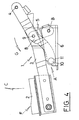
- Fig. 7 diagrammatically shows a first embodiment of the safety hinge 13 for front bonnets 14 of cars according to the invention.
- the safety hinge 13 is essentially made up of the following elements: a push-bar 15 joined by a first end to the bonnet 14 and joined by its other end to a first and second hinged point, 16 and 17 respectively; and a structure 18 which supports the two hinged points 16 and 17 and which is fixed to the chassis 22 of the vehicle at two joining points, A and B respectively, being point A displaceable when the bonnet 14 receives an impact greater than a predetermined value and the articulated point B, all this adapted to so that, in a similar way to what was explained earlier for the embodiments in Figs. 1 to 3 , when point A is displaced, the structure 18 turns around point B, the hinged points 16 and 17 and the bonnet 14 being displaced downwards.
- the structure 18 is formed by a first and second bar, 19 and 20 respectively, and by a support bar 21. From these bars, the first bar 19 has one of its ends connected to the first hinged point 16 while its other end is joined in an articulated way to a first intermediate point 23 of the support bar 21; the second bar 20 has one of its ends joined to the second hinged point 17 while its other end is joined in an articulated way to a second intermediate point 24 of the support bar 21; and the support bar 21 is joined by its ends to the chassis 22 at points A and B, respectively.
- the safety hinge 13 can be seen to comprise a push-bar 15 joined by one of its ends to the bonnet 14, while its other end has an extension 25 whereon the first and second hinged points 16 and 17 are positioned respectively.
- the structure 18 comprises a first and second bar, 18 and 19 respectively, and a support bar 21.
- the ends of the first bar 18 are joined in an articulated way to the first hinged point 16 and to a first intermediate point 23 of the support bar 21 respectively;
- the second bar 20 has its ends joined in an articulated way to the second hinged point 17 and to a second intermediate point 24 of the support bar 21 respectively; and one of the ends of the support bar 21 is joined in an articulated way to the chassis 22 by point B, and its other end forms displaceable point A.
- the structure 18 has a detaching body 26 on the displaceable point A which generally has a tubular cylindrical shape which forms part of the support bar 21, and which is removably coupled to the chassis 22 by means of a housing 27 which has an opening 28; all this being adapted in such a way that the detaching body 26 is forced through the opening 28 via plastic or elastic deformation of the detaching body 26.
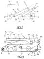
- Fig. 8 represents the safety hinge 13 of the invention in the position with the bonnet 14 closed.
- the user To open the bonnet 14 the user must turn it in the direction shown as H, causing the bars 19 and 20 to turn around the articulated points 23 and 24 connected to the support bar 21 while the bonnet, in a compound movement, turns in the direction shown by the arrow H in Fig. 8 ; obviously, in order for the bonnet 14 to close by reaching the position shown in Fig. 8 it turns in the opposite direction to before, i.e. in the direction shown as I.
- the support bar 21 maintains its position with respect to the vehicle's chassis 22.
Landscapes
- Engineering & Computer Science (AREA)
- Mechanical Engineering (AREA)
- Chemical & Material Sciences (AREA)
- Combustion & Propulsion (AREA)
- Transportation (AREA)
- Superstructure Of Vehicle (AREA)
Abstract
Description
- The invention relates to a safety hinge for front car bonnets, of the type which comprise a push-bar which forms part of the vehicle's bonnet, joined to the vehicle's chassis for opening and closing the bonnet via at least one hinged point, which is displaced when the bonnet receives an impact which is stronger than a predetermined value.
- In order to minimize the harm a car may cause to a pedestrian, especially in the event of a head-on collision between the car and the pedestrian, some cars have systems for absorbing part of the force of the impact or collision, so that the pedestrian does not receive such a severe blow when hit by the vehicle.
- To that effect, different devices are known whereby the front bonnets of cars, upon receiving an impact of a predetermined force, absorb part of the force of the impact by being displaced to cushion the reaction force that the bonnet might apply to the pedestrian.
- The former rigid articulations whereby the bonnet was fixed to the chassis of the vehicle are being replaced by hinges which allow opening and closing of the bonnet under normal conditions, so that they are substantially displaced when the bonnet receives an impact upon hitting a pedestrian, and also displacing the part of the bonnet close to the hinge to absorb some of the force of the impact.
- The patent documents
EP 1178917 andWO 03/012233 - Unlike previous documents, the hinge device described in patent document
US 6588526 introduces elastic means, such as a spring, whereon the hinged point is supported in such a way that it is displaced upon receiving an impact. However, the use of springs becomes a problem since the hinged point, when not fixed to the vehicle's chassis, can produce vibrations when the car is moving, causing continued rattling or other form of noise. - In order to provide a solution to the aforementioned problems, the safety hinge being the object of the invention will be disclosed. The safety hinge for front car bonnets in the invention comprises a push-bar which forms part of the vehicle's bonnet, joined to the vehicle's chassis for opening and closing the bonnet via two hinged points which are displaced when the bonnet receives an impact which is stronger than a predetermined value.
- The safety hinge is further characterized in that the structure which supports the two hinged points is formed by two bars whereon on one of their respective ends is a corresponding hinged point, while their other respective ends are joined in an articulated way to a support bar, the support point articulated with the chassis being on one of the ends of the support bar, while on the other end is the displaceable joining point.
- Such characteristics of the structure enable the hinge to move in the event of an impact in such a way that said hinged points pull the bonnet in its movement.
- The structure preferably comprises, in the joining point which can be displaced with respect to the chassis, a detaching body, removably coupled in a hollow housing which forms part of the vehicle's chassis, whose cavity has a similar configuration to that of the detaching body and is adapted to tightly house the latter.
- In an embodiment of the invention, the detaching body is essentially tubular in shape and the housing has an opening which is narrower than the diameter of the detaching body, whereby the latter is forced through the opening, via plastic or elastic deformation of the detaching body and/or of the housing.
- The attached drawings show, in a non-limitative way, four diagrammatic forms of embodiment of the hinge being the object of the invention and two preferred examples of embodiment. In said drawings:
- Figs. 1, 2 and 3
- are respective diagrammatic forms of some embodiments of hinges not forming part of the claimed of the invention, with a sole hinged point;
- Fig. 4
- is a side view of an example of a embodiment of a hinge not forming part of the claimed invention in a position with the bonnet closed, corresponding to the diagrammatic embodiment in
Fig. 1 ; - Fig. 5
- is a side view of the hinge in
Fig. 4 in a position with the bonnet open; - Fig. 6,
- is a side view of the hinge in
Figs. 4 and5 with the structure which joins it to the chassis of the vehicle being displaced; - Fig. 7
- is a diagrammatic embodiment of a hinge according to the invention, with two hinged points; and
- Fig. 8,
- is a side view of another preferred example of embodiment of a hinge according to the invention, in a position with the bonnet closed, corresponding to the diagrammatic embodiment in
Fig. 7 . - In
Figs. 1, 2 and 3 respective diagrammatic forms of embodiment of asafety hinge 1 are described forfront bonnets 2 of cars not forming part of the invention. In all of these, it can be seen that thesafety hinge 1 is essentially made up of the following elements: a push-bar 3 joined by a first end to thebonnet 2 and joined by its other end to ahinged point 4, around which said push-bar 3 can be turned in both directions, corresponding with the turn of the bonnet between a closed position and an open position; and astructure 5 which supports thehinged point 4 and which is fixed to thechassis 6 of the vehicle by two joining points, A and B respectively, wherein point A is displaced when thebonnet 2 receives an impact greater than a predetermined value, and point B is articulated, all this being adapted in such a way that when point A is displaced, thestructure 5 turns around point B displacing the hingedpoint 4 and thebonnet 2 downwards. - In
Fig. 1 , which corresponds to a first diagrammatic embodiment, it can be seen that thestructure 5 is formed by twobars bar 7 and asupport bar 8, respectively, joined together in an articulated way, displaceable point A being situated on the detachingbar 7, and the articulated point B being situated on thesupport bar 8. - In
Fig. 2 , which corresponds to a second diagrammatic embodiment, it can be seen that thestructure 5 is similar to that in the first embodiment inFig. 1 , only differing in the fact that the displaceable point A is situated on thesupport bar 8, and the articulated point B is situated on the detachingbar 7. - In
Fig. 3 , which corresponds to a third diagrammatic embodiment, it can be seen that thestructure 5 is similar to that of the first and second embodiments represented inFigs. 1 and 2 , respectively, the embodiment inFig. 3 differing only from the embodiment inFig. 2 by the fact that the detachingbar 7 and thesupport bar 8 are joined in a non-articulated way, or simply form part of the same body. Naturally, in a practical embodiment, instead ofbars structure 5 could be formed, as mentioned earlier, by a single body or block, for which reason, thestructure 5 is designed to be formed, for example, by an essentially flat, rigid sheet whereon points A, B and thehinged point 4 would be situated. - In the three forms of embodiment described, it can be seen that points A and B and the join between the detaching
bar 7 and thesupport bar 8 form an imaginary triangle, on the base whereof is an imaginary line which links the joining points of thebars said bars - As indicated above, in
Figs. 4 ,5 and6 an embodiment is represented which corresponds to the first diagrammatic embodiment of the safety hinge for front car bonnets. InFigs. 4 ,5 and6 thehinge 1 is represented in different operating positions: inFig. 4 thehinge 1 is represented in a position with thebonnet 2 closed; inFig. 5 thehinge 1 is represented in a position with thebonnet 2 open; and inFig. 6 thehinge 1 is represented after thebonnet 2 of the vehicle has received an impact. - To help simplify the following description, the same numerical references have been used in
Figs. 1, 2 and 3 to indicate the same or similar components of the safety hinge of the invention. - In
Figs. 4 and5 , it can be seen that thesafety hinge 1 comprises a push-bar 3 joined by a first end to thebonnet 2, while its other end is joined to a hingedpoint 4 supported by astructure 5 fixed to thechassis 6, all this adapted in such a way that thebonnet 2 can be turned around the hingedpoint 4 in both directions indicated as C inFig. 4 , in order to open it, and as D inFig. 5 , in order to close it. - The
structure 5 is made up of a detachingbar 7 and asupport bar 8. One of the ends of the detachingbar 7 is joined in an articulated way to the push-bar 3 forming thehinged point 4, while its other end is joined to thechassis 6 and forms the displaceable joining point A, which is described below. One of the ends of thesupport bar 8 is joined in an articulated way to anintermediate point 9 on the detachingbar 7, while its other end is joined in an articulated way to thechassis 6 of the vehicle and forms articulation point B, all this adapted in such a way that thesupport bar 8 can turn around the articulation point B and around theintermediate point 9, and in each case, in both directions, in the event of impact. - The
structure 5 includes, on the displaceable point A, a detachingbody 10 which generally has a tubular cylindrical shape which forms part of the detachingbar 7 and which is removably coupled to ahousing 11 with anopening 12, represented inFig. 6 , and which is on thechassis 6; all this being adapted in such a way that the detachingbody 10 is forced through theopening 12, via plastic or elastic deformation of the detachingbody 10. It is understood that the elements forming the displaceable point A can adopt other configurations, for example, that forcing of the detaching body through the opening is done essentially via the plastic deformation of the housing, or via the simultaneous plastic deformation of the detaching body and the housing. - It is noted here that the join between the
structure 5 and thechassis 6 of the vehicle can be direct, whereby thehousing 11 and the articulation point B would form part of, or would be integrated in, the chassis itself, or indirectly, via an auxiliary intermediate body forming part of thechassis 6 of the vehicle, with theaforementioned housing 11 and the corresponding articulated joint. - In the same way, the inventor provided for the detaching
body 10 to have a deformable covering in the area where it is coupled to thehousing 11, which enables the housing unit to be detached, so that thehousing body 10 is not damaged or does not deteriorate so that said covering can be replaced for reuse. - An explanation of how the safety hinge for front car bonnets of the above described invention functions is given below.
- In
Fig. 4 the safety hinge of the invention is represented in a position with thebonnet 2 closed; in these circumstances, in order to open thebonnet 2, the user must turn it in the direction shown as C, causing the push-bar 3 to turn around thehinged point 4, until thebonnet 2 reaches the open position shown inFig. 5 . In a similar way, in order for thebonnet 2 to close, the user must turn it in the direction shown as D inFig. 5 , causing the push-bar 3 to turn around thehinged point 4, until it reaches the closed position shown inFig. 4 . It is now shown that during opening and closing of thebonnet 2 the hingedpoint 4 has maintained its position with respect to thechassis 6. - If there is an impact on the
bonnet 2, such as that produced, for example, by a collision with a pedestrian, the hinge functions as follows. Said impact produces a force F, shown inFig. 4 , applied to thebonnet 2 which is transmitted to the push-bar 3 and through the hingedpoint 4 to the detachingbar 7; if said force F reaches an intensity of a predetermined value, the detachingbody 10 is forced out of itshousing 11 in thechassis 6, and at the same time thesupport bar 8 turns around the articulation point B in the direction shown as G inFig. 4 , until thehinge 1 reaches the detaching position shown inFig. 6 , wherein the hingedpoint 4 occupies a position on thechassis 6 below which it previously occupied at the time thebonnet 2 received said impact, in such a way managing to reduce the harm that may have been suffered by the pedestrian as a result of the collision. -
Fig. 7 diagrammatically shows a first embodiment of thesafety hinge 13 forfront bonnets 14 of cars according to the invention. It can be seen that thesafety hinge 13 is essentially made up of the following elements: a push-bar 15 joined by a first end to thebonnet 14 and joined by its other end to a first and second hinged point, 16 and 17 respectively; and astructure 18 which supports the twohinged points chassis 22 of the vehicle at two joining points, A and B respectively, being point A displaceable when thebonnet 14 receives an impact greater than a predetermined value and the articulated point B, all this adapted to so that, in a similar way to what was explained earlier for the embodiments inFigs. 1 to 3 , when point A is displaced, thestructure 18 turns around point B, thehinged points bonnet 14 being displaced downwards. - The
structure 18 is formed by a first and second bar, 19 and 20 respectively, and by asupport bar 21. From these bars, thefirst bar 19 has one of its ends connected to the firsthinged point 16 while its other end is joined in an articulated way to a firstintermediate point 23 of thesupport bar 21; thesecond bar 20 has one of its ends joined to the secondhinged point 17 while its other end is joined in an articulated way to a secondintermediate point 24 of thesupport bar 21; and thesupport bar 21 is joined by its ends to thechassis 22 at points A and B, respectively. - In the description that follows, the same numerical references have been used as in
Fig. 7 to indicate the same or similar components of the safety hinge of the invention which, as an example of embodiment, is represented inFig. 8 , the safety hinge being represented in this figure with the bonnet closed. - In
Fig. 8 thesafety hinge 13 can be seen to comprise a push-bar 15 joined by one of its ends to thebonnet 14, while its other end has anextension 25 whereon the first and second hingedpoints structure 18 comprises a first and second bar, 18 and 19 respectively, and asupport bar 21. The ends of thefirst bar 18 are joined in an articulated way to the first hingedpoint 16 and to a firstintermediate point 23 of thesupport bar 21 respectively; thesecond bar 20 has its ends joined in an articulated way to the second hingedpoint 17 and to a secondintermediate point 24 of thesupport bar 21 respectively; and one of the ends of thesupport bar 21 is joined in an articulated way to thechassis 22 by point B, and its other end forms displaceable point A. - In a similar way, as explained for the example of embodiment shown in
Figs. 4 to 6 , thestructure 18 has a detachingbody 26 on the displaceable point A which generally has a tubular cylindrical shape which forms part of thesupport bar 21, and which is removably coupled to thechassis 22 by means of ahousing 27 which has anopening 28; all this being adapted in such a way that the detachingbody 26 is forced through theopening 28 via plastic or elastic deformation of the detachingbody 26. - The functioning of the hinge of the invention represented in
Fig. 8 does not essentially differ from the one explained earlier for the embodiment represented inFigs. 4 to 6 , and which is described in a more simplified way below. - As indicated,
Fig. 8 represents thesafety hinge 13 of the invention in the position with thebonnet 14 closed. To open thebonnet 14 the user must turn it in the direction shown as H, causing thebars points support bar 21 while the bonnet, in a compound movement, turns in the direction shown by the arrow H inFig. 8 ; obviously, in order for thebonnet 14 to close by reaching the position shown inFig. 8 it turns in the opposite direction to before, i.e. in the direction shown as I. It is noted in this point that, during opening and closing of the bonnet, 14 thesupport bar 21 maintains its position with respect to the vehicle'schassis 22. - If there is an impact against the
bonnet 14, such as that produced by hitting a pedestrian, said impact produces a force shown as J inFig. 8 which is transmitted to displaceable point A by displacement of the push-bar 15, which runs up against thesupport bar 21 causing, if said impact is greater than a predetermined value, the detachingbody 26, which has a support bar, to be forced out of itshousing 27 in thechassis 22 of the vehicle, and consequently the displacement of thebonnet 14 downwards, in such a way reducing the harm that may be suffered by the pedestrian as a result of the collision.
Claims (3)
- Safety hinge (13) for front bonnets (14) of cars, which comprises a push-bar (15) which forms part of the bonnet (14) of the vehicle, joined to the vehicle's chassis for opening and closing the bonnet (14) by at least two hinged points (16, 17) which are displaced when the bonnet (14) receives an impact greater than a predetermined value, said hinged points (16, 17) being joined to the vehicle's chassis (22) by means of a structure (18), originally fixed to the chassis by at least two joining points (A, B), one of these (A) being displaceable when the bonnet (14) receives the impact while the second (B) is articulated, whereby upon the structure (18) being displaced by the first joining point (A), the structure turns around the articulated point (B), pulling the hinged points (16, 17) in its movement, the safety hinge being characterized in that the structure which supports the two hinged points (16, 17) is formed by two bars (19, 20) whereon on one of their respective ends is a corresponding hinged point (16, 17), while their other respective ends are joined in an articulated way (23, 24) to a support bar (21), the support point (A) articulated with the chassis (22) being on one of the ends of the support bar (21), while on the other end is the displaceable joining point (B).
- Safety hinge (13) according to claim 1, characterized in that the structure (18) comprises, in the joining point (A), which is displaceable with respect to the chassis (22), a detaching body (26), removably coupled to a hollow housing (27) which forms part of the vehicle's chassis (22), whose cavity has a similar configuration to that of the detaching body (26) and is adapted to tightly house the latter.
- Safety hinge (13) according to preceding claims, characterized in that the detaching body (26) is essentially tubular in shape and the housing (27) has an opening (28) which is narrower than the diameter of the detaching body, whereby the latter is forced through the opening via plastic or elastic deformation of the detaching body and/or of the housing.
Priority Applications (1)
| Application Number | Priority Date | Filing Date | Title |
|---|---|---|---|
| PL09177798T PL2154033T3 (en) | 2004-05-13 | 2005-04-20 | Safety hinge for front car bonnets |
Applications Claiming Priority (2)
| Application Number | Priority Date | Filing Date | Title |
|---|---|---|---|
| ES200401148A ES2259874B1 (en) | 2004-05-13 | 2004-05-13 | SAFETY HINGE FOR FRONT COATS OF MOTOR VEHICLES. |
| EP05735619A EP1747123B1 (en) | 2004-05-13 | 2005-04-20 | Safety hinge for front car bonnets |
Related Parent Applications (3)
| Application Number | Title | Priority Date | Filing Date |
|---|---|---|---|
| EP05735619A Division-Into EP1747123B1 (en) | 2004-05-13 | 2005-04-20 | Safety hinge for front car bonnets |
| EP05735619A Division EP1747123B1 (en) | 2004-05-13 | 2005-04-20 | Safety hinge for front car bonnets |
| EP05735619.8 Division | 2005-04-20 |
Publications (3)
| Publication Number | Publication Date |
|---|---|
| EP2154033A1 true EP2154033A1 (en) | 2010-02-17 |
| EP2154033B1 EP2154033B1 (en) | 2011-02-23 |
| EP2154033B9 EP2154033B9 (en) | 2011-04-27 |
Family
ID=34965591
Family Applications (2)
| Application Number | Title | Priority Date | Filing Date |
|---|---|---|---|
| EP09177798A Expired - Lifetime EP2154033B9 (en) | 2004-05-13 | 2005-04-20 | Safety hinge for front car bonnets |
| EP05735619A Expired - Lifetime EP1747123B1 (en) | 2004-05-13 | 2005-04-20 | Safety hinge for front car bonnets |
Family Applications After (1)
| Application Number | Title | Priority Date | Filing Date |
|---|---|---|---|
| EP05735619A Expired - Lifetime EP1747123B1 (en) | 2004-05-13 | 2005-04-20 | Safety hinge for front car bonnets |
Country Status (6)
| Country | Link |
|---|---|
| EP (2) | EP2154033B9 (en) |
| AT (2) | ATE456493T1 (en) |
| DE (2) | DE602005026596D1 (en) |
| ES (3) | ES2259874B1 (en) |
| PL (2) | PL2154033T3 (en) |
| WO (1) | WO2005113301A1 (en) |
Families Citing this family (3)
| Publication number | Priority date | Publication date | Assignee | Title |
|---|---|---|---|---|
| DE102008014767A1 (en) * | 2008-03-18 | 2009-09-24 | Bayerische Motoren Werke Aktiengesellschaft | Protection device for bonnet of vehicle, has stop which is fastened on support element or on part fixed on it, on which closed bonnet rests, where closed bonnet is deformed in elastic or plastic manner |
| DE602008005262D1 (en) * | 2008-03-31 | 2011-04-14 | Ford Global Tech Llc | hood hinge |
| DE102009013262A1 (en) * | 2009-03-14 | 2010-09-16 | Bayerische Motoren Werke Aktiengesellschaft | Hinge device for a front flap of a motor vehicle |
Citations (6)
| Publication number | Priority date | Publication date | Assignee | Title |
|---|---|---|---|---|
| JPH1120740A (en) * | 1997-06-27 | 1999-01-26 | Nissan Motor Co Ltd | Car hood mounting structure |
| DE19948459A1 (en) * | 1999-10-08 | 2001-05-17 | Edscha Ag | Front bonnet arrangement, especially for private motor vehicle, has at least one link with joint located on part of bonnet and on vehicle and which is positionally adjustable under load of impacting pedestrian |
| EP1178917A1 (en) | 1999-05-17 | 2002-02-13 | Edscha AG | Front hood system |
| DE10116716A1 (en) * | 2001-04-04 | 2002-10-10 | Volkswagen Ag | Hinge unit for vehicle bonnet for raising into impact position has support fixed on vehicle and energy accumulator with adjusting member to raise up bonnet in event of collision with e.g. pedestrian |
| WO2003012233A1 (en) | 2001-07-28 | 2003-02-13 | Adam Opel Ag | Dual-arm articulated hinge for the front bonnet of a motor vehicle |
| US6588526B1 (en) | 1999-05-17 | 2003-07-08 | Edsca Ag | Front hood assembly |
Family Cites Families (2)
| Publication number | Priority date | Publication date | Assignee | Title |
|---|---|---|---|---|
| DE19922107C1 (en) * | 1999-05-17 | 2001-01-18 | Edscha Ag | Front hood assembly for motor vehicle has multijoint hinge with connecting rod which pivot front hood to chassis, such that connecting rod varies in length under collision impact |
| DE10136901A1 (en) * | 2001-07-28 | 2003-02-06 | Opel Adam Ag | Bodywork with yielding bonnet (hood) has pivot mounted on cantilever which tilts inward under frontal impact |
-
2004
- 2004-05-13 ES ES200401148A patent/ES2259874B1/en not_active Expired - Fee Related
-
2005
- 2005-04-20 ES ES09177798T patent/ES2361245T3/en not_active Expired - Lifetime
- 2005-04-20 AT AT05735619T patent/ATE456493T1/en not_active IP Right Cessation
- 2005-04-20 ES ES05735619T patent/ES2337701T3/en not_active Expired - Lifetime
- 2005-04-20 WO PCT/EP2005/004251 patent/WO2005113301A1/en not_active Ceased
- 2005-04-20 EP EP09177798A patent/EP2154033B9/en not_active Expired - Lifetime
- 2005-04-20 PL PL09177798T patent/PL2154033T3/en unknown
- 2005-04-20 PL PL05735619T patent/PL1747123T3/en unknown
- 2005-04-20 AT AT09177798T patent/ATE499246T1/en not_active IP Right Cessation
- 2005-04-20 EP EP05735619A patent/EP1747123B1/en not_active Expired - Lifetime
- 2005-04-20 DE DE602005026596T patent/DE602005026596D1/en not_active Expired - Lifetime
- 2005-04-20 DE DE602005019152T patent/DE602005019152D1/en not_active Expired - Lifetime
Patent Citations (6)
| Publication number | Priority date | Publication date | Assignee | Title |
|---|---|---|---|---|
| JPH1120740A (en) * | 1997-06-27 | 1999-01-26 | Nissan Motor Co Ltd | Car hood mounting structure |
| EP1178917A1 (en) | 1999-05-17 | 2002-02-13 | Edscha AG | Front hood system |
| US6588526B1 (en) | 1999-05-17 | 2003-07-08 | Edsca Ag | Front hood assembly |
| DE19948459A1 (en) * | 1999-10-08 | 2001-05-17 | Edscha Ag | Front bonnet arrangement, especially for private motor vehicle, has at least one link with joint located on part of bonnet and on vehicle and which is positionally adjustable under load of impacting pedestrian |
| DE10116716A1 (en) * | 2001-04-04 | 2002-10-10 | Volkswagen Ag | Hinge unit for vehicle bonnet for raising into impact position has support fixed on vehicle and energy accumulator with adjusting member to raise up bonnet in event of collision with e.g. pedestrian |
| WO2003012233A1 (en) | 2001-07-28 | 2003-02-13 | Adam Opel Ag | Dual-arm articulated hinge for the front bonnet of a motor vehicle |
Non-Patent Citations (1)
| Title |
|---|
| PATENT ABSTRACTS OF JAPAN vol. 1999, no. 4 30 April 1999 (1999-04-30) * |
Also Published As
| Publication number | Publication date |
|---|---|
| ATE456493T1 (en) | 2010-02-15 |
| EP1747123B1 (en) | 2010-01-27 |
| EP1747123A1 (en) | 2007-01-31 |
| ES2259874A1 (en) | 2006-10-16 |
| ES2259874B1 (en) | 2007-09-16 |
| ES2337701T3 (en) | 2010-04-28 |
| ATE499246T1 (en) | 2011-03-15 |
| DE602005019152D1 (en) | 2010-03-18 |
| EP2154033B1 (en) | 2011-02-23 |
| EP2154033B9 (en) | 2011-04-27 |
| ES2361245T3 (en) | 2011-06-15 |
| PL1747123T3 (en) | 2010-06-30 |
| WO2005113301A1 (en) | 2005-12-01 |
| DE602005026596D1 (en) | 2011-04-07 |
| PL2154033T3 (en) | 2011-05-31 |
Similar Documents
| Publication | Publication Date | Title |
|---|---|---|
| CN101198511B (en) | Pedestrian protection automotive hood hinge assembly | |
| EP0641707B1 (en) | Vehicle bonnets | |
| EP1497570B1 (en) | Collision energy-absorbing device | |
| US7828100B2 (en) | Front hood assembly | |
| US7410027B2 (en) | Device for reducing the impact for pedestrians | |
| JP4410823B2 (en) | Pop-up hood device for vehicle | |
| CN110116701A (en) | Hinge apparatus | |
| US12083988B2 (en) | Drive device for a vehicle flap | |
| CZ20014010A3 (en) | Arrangement of front bonnet | |
| JP4249133B2 (en) | Hinge to connect the hood, especially the engine hood to the car body | |
| JP2007501161A (en) | A device that manually reverses a device that protects people in the event of a frontal collision with an automobile | |
| EP2154033B1 (en) | Safety hinge for front car bonnets | |
| EP2106976B1 (en) | Hood hinge | |
| JP3842022B2 (en) | Vehicle hood device | |
| EP3184377B1 (en) | Hinge arrangement | |
| GB2372536A (en) | A hinge assembly and a motor vehicle including the same | |
| EP3184376B1 (en) | Hinge arrangement | |
| CN205805259U (en) | A kind of automobile engine hood hinge assembly that can be used for pedestrian protecting | |
| JPH0686216B2 (en) | Car steering support device | |
| JPH01195176A (en) | Steering support structure for automobile |
Legal Events
| Date | Code | Title | Description |
|---|---|---|---|
| PUAI | Public reference made under article 153(3) epc to a published international application that has entered the european phase |
Free format text: ORIGINAL CODE: 0009012 |
|
| AC | Divisional application: reference to earlier application |
Ref document number: 1747123 Country of ref document: EP Kind code of ref document: P |
|
| AK | Designated contracting states |
Kind code of ref document: A1 Designated state(s): AT BE BG CH CY CZ DE DK EE ES FI FR GB GR HU IE IS IT LI LT LU MC NL PL PT RO SE SI SK TR |
|
| 17P | Request for examination filed |
Effective date: 20100816 |
|
| GRAP | Despatch of communication of intention to grant a patent |
Free format text: ORIGINAL CODE: EPIDOSNIGR1 |
|
| RIC1 | Information provided on ipc code assigned before grant |
Ipc: B60R 21/34 20060101AFI20100908BHEP Ipc: E05D 3/06 20060101ALI20100908BHEP |
|
| GRAS | Grant fee paid |
Free format text: ORIGINAL CODE: EPIDOSNIGR3 |
|
| GRAA | (expected) grant |
Free format text: ORIGINAL CODE: 0009210 |
|
| AC | Divisional application: reference to earlier application |
Ref document number: 1747123 Country of ref document: EP Kind code of ref document: P |
|
| AK | Designated contracting states |
Kind code of ref document: B1 Designated state(s): AT BE BG CH CY CZ DE DK EE ES FI FR GB GR HU IE IS IT LI LT LU MC NL PL PT RO SE SI SK TR |
|
| REG | Reference to a national code |
Ref country code: GB Ref legal event code: FG4D |
|
| REG | Reference to a national code |
Ref country code: CH Ref legal event code: EP |
|
| REG | Reference to a national code |
Ref country code: IE Ref legal event code: FG4D |
|
| REF | Corresponds to: |
Ref document number: 602005026596 Country of ref document: DE Date of ref document: 20110407 Kind code of ref document: P |
|
| REG | Reference to a national code |
Ref country code: DE Ref legal event code: R096 Ref document number: 602005026596 Country of ref document: DE Effective date: 20110407 |
|
| REG | Reference to a national code |
Ref country code: PL Ref legal event code: T3 |
|
| REG | Reference to a national code |
Ref country code: ES Ref legal event code: FG2A Ref document number: 2361245 Country of ref document: ES Kind code of ref document: T3 Effective date: 20110615 |
|
| REG | Reference to a national code |
Ref country code: NL Ref legal event code: VDEP Effective date: 20110223 |
|
| LTIE | Lt: invalidation of european patent or patent extension |
Effective date: 20110223 |
|
| PG25 | Lapsed in a contracting state [announced via postgrant information from national office to epo] |
Ref country code: GR Free format text: LAPSE BECAUSE OF FAILURE TO SUBMIT A TRANSLATION OF THE DESCRIPTION OR TO PAY THE FEE WITHIN THE PRESCRIBED TIME-LIMIT Effective date: 20110524 Ref country code: LT Free format text: LAPSE BECAUSE OF FAILURE TO SUBMIT A TRANSLATION OF THE DESCRIPTION OR TO PAY THE FEE WITHIN THE PRESCRIBED TIME-LIMIT Effective date: 20110223 Ref country code: SE Free format text: LAPSE BECAUSE OF FAILURE TO SUBMIT A TRANSLATION OF THE DESCRIPTION OR TO PAY THE FEE WITHIN THE PRESCRIBED TIME-LIMIT Effective date: 20110223 Ref country code: PT Free format text: LAPSE BECAUSE OF FAILURE TO SUBMIT A TRANSLATION OF THE DESCRIPTION OR TO PAY THE FEE WITHIN THE PRESCRIBED TIME-LIMIT Effective date: 20110623 |
|
| PG25 | Lapsed in a contracting state [announced via postgrant information from national office to epo] |
Ref country code: SI Free format text: LAPSE BECAUSE OF FAILURE TO SUBMIT A TRANSLATION OF THE DESCRIPTION OR TO PAY THE FEE WITHIN THE PRESCRIBED TIME-LIMIT Effective date: 20110223 Ref country code: BG Free format text: LAPSE BECAUSE OF FAILURE TO SUBMIT A TRANSLATION OF THE DESCRIPTION OR TO PAY THE FEE WITHIN THE PRESCRIBED TIME-LIMIT Effective date: 20110523 Ref country code: AT Free format text: LAPSE BECAUSE OF FAILURE TO SUBMIT A TRANSLATION OF THE DESCRIPTION OR TO PAY THE FEE WITHIN THE PRESCRIBED TIME-LIMIT Effective date: 20110223 Ref country code: NL Free format text: LAPSE BECAUSE OF FAILURE TO SUBMIT A TRANSLATION OF THE DESCRIPTION OR TO PAY THE FEE WITHIN THE PRESCRIBED TIME-LIMIT Effective date: 20110223 Ref country code: BE Free format text: LAPSE BECAUSE OF FAILURE TO SUBMIT A TRANSLATION OF THE DESCRIPTION OR TO PAY THE FEE WITHIN THE PRESCRIBED TIME-LIMIT Effective date: 20110223 Ref country code: CY Free format text: LAPSE BECAUSE OF FAILURE TO SUBMIT A TRANSLATION OF THE DESCRIPTION OR TO PAY THE FEE WITHIN THE PRESCRIBED TIME-LIMIT Effective date: 20110223 Ref country code: FI Free format text: LAPSE BECAUSE OF FAILURE TO SUBMIT A TRANSLATION OF THE DESCRIPTION OR TO PAY THE FEE WITHIN THE PRESCRIBED TIME-LIMIT Effective date: 20110223 |
|
| PG25 | Lapsed in a contracting state [announced via postgrant information from national office to epo] |
Ref country code: EE Free format text: LAPSE BECAUSE OF FAILURE TO SUBMIT A TRANSLATION OF THE DESCRIPTION OR TO PAY THE FEE WITHIN THE PRESCRIBED TIME-LIMIT Effective date: 20110223 Ref country code: DK Free format text: LAPSE BECAUSE OF FAILURE TO SUBMIT A TRANSLATION OF THE DESCRIPTION OR TO PAY THE FEE WITHIN THE PRESCRIBED TIME-LIMIT Effective date: 20110223 |
|
| PG25 | Lapsed in a contracting state [announced via postgrant information from national office to epo] |
Ref country code: RO Free format text: LAPSE BECAUSE OF FAILURE TO SUBMIT A TRANSLATION OF THE DESCRIPTION OR TO PAY THE FEE WITHIN THE PRESCRIBED TIME-LIMIT Effective date: 20110223 Ref country code: SK Free format text: LAPSE BECAUSE OF FAILURE TO SUBMIT A TRANSLATION OF THE DESCRIPTION OR TO PAY THE FEE WITHIN THE PRESCRIBED TIME-LIMIT Effective date: 20110223 Ref country code: CZ Free format text: LAPSE BECAUSE OF FAILURE TO SUBMIT A TRANSLATION OF THE DESCRIPTION OR TO PAY THE FEE WITHIN THE PRESCRIBED TIME-LIMIT Effective date: 20110223 Ref country code: MC Free format text: LAPSE BECAUSE OF NON-PAYMENT OF DUE FEES Effective date: 20110430 |
|
| REG | Reference to a national code |
Ref country code: CH Ref legal event code: PL |
|
| PLBE | No opposition filed within time limit |
Free format text: ORIGINAL CODE: 0009261 |
|
| STAA | Information on the status of an ep patent application or granted ep patent |
Free format text: STATUS: NO OPPOSITION FILED WITHIN TIME LIMIT |
|
| GBPC | Gb: european patent ceased through non-payment of renewal fee |
Effective date: 20110523 |
|
| PG25 | Lapsed in a contracting state [announced via postgrant information from national office to epo] |
Ref country code: CH Free format text: LAPSE BECAUSE OF NON-PAYMENT OF DUE FEES Effective date: 20110430 Ref country code: LI Free format text: LAPSE BECAUSE OF NON-PAYMENT OF DUE FEES Effective date: 20110430 |
|
| 26N | No opposition filed |
Effective date: 20111124 |
|
| REG | Reference to a national code |
Ref country code: IE Ref legal event code: MM4A |
|
| REG | Reference to a national code |
Ref country code: DE Ref legal event code: R097 Ref document number: 602005026596 Country of ref document: DE Effective date: 20111124 |
|
| PG25 | Lapsed in a contracting state [announced via postgrant information from national office to epo] |
Ref country code: IE Free format text: LAPSE BECAUSE OF NON-PAYMENT OF DUE FEES Effective date: 20110420 |
|
| PG25 | Lapsed in a contracting state [announced via postgrant information from national office to epo] |
Ref country code: IT Free format text: LAPSE BECAUSE OF FAILURE TO SUBMIT A TRANSLATION OF THE DESCRIPTION OR TO PAY THE FEE WITHIN THE PRESCRIBED TIME-LIMIT Effective date: 20110223 |
|
| PG25 | Lapsed in a contracting state [announced via postgrant information from national office to epo] |
Ref country code: GB Free format text: LAPSE BECAUSE OF NON-PAYMENT OF DUE FEES Effective date: 20110523 |
|
| PG25 | Lapsed in a contracting state [announced via postgrant information from national office to epo] |
Ref country code: LU Free format text: LAPSE BECAUSE OF NON-PAYMENT OF DUE FEES Effective date: 20110420 |
|
| PG25 | Lapsed in a contracting state [announced via postgrant information from national office to epo] |
Ref country code: IS Free format text: LAPSE BECAUSE OF FAILURE TO SUBMIT A TRANSLATION OF THE DESCRIPTION OR TO PAY THE FEE WITHIN THE PRESCRIBED TIME-LIMIT Effective date: 20110223 |
|
| PG25 | Lapsed in a contracting state [announced via postgrant information from national office to epo] |
Ref country code: TR Free format text: LAPSE BECAUSE OF FAILURE TO SUBMIT A TRANSLATION OF THE DESCRIPTION OR TO PAY THE FEE WITHIN THE PRESCRIBED TIME-LIMIT Effective date: 20110223 |
|
| PG25 | Lapsed in a contracting state [announced via postgrant information from national office to epo] |
Ref country code: HU Free format text: LAPSE BECAUSE OF FAILURE TO SUBMIT A TRANSLATION OF THE DESCRIPTION OR TO PAY THE FEE WITHIN THE PRESCRIBED TIME-LIMIT Effective date: 20110223 |
|
| REG | Reference to a national code |
Ref country code: FR Ref legal event code: PLFP Year of fee payment: 12 |
|
| REG | Reference to a national code |
Ref country code: FR Ref legal event code: PLFP Year of fee payment: 13 |
|
| PGFP | Annual fee paid to national office [announced via postgrant information from national office to epo] |
Ref country code: PL Payment date: 20170317 Year of fee payment: 13 |
|
| PGFP | Annual fee paid to national office [announced via postgrant information from national office to epo] |
Ref country code: ES Payment date: 20170321 Year of fee payment: 13 |
|
| PGFP | Annual fee paid to national office [announced via postgrant information from national office to epo] |
Ref country code: FR Payment date: 20170426 Year of fee payment: 13 Ref country code: DE Payment date: 20170419 Year of fee payment: 13 |
|
| REG | Reference to a national code |
Ref country code: DE Ref legal event code: R119 Ref document number: 602005026596 Country of ref document: DE |
|
| PG25 | Lapsed in a contracting state [announced via postgrant information from national office to epo] |
Ref country code: DE Free format text: LAPSE BECAUSE OF NON-PAYMENT OF DUE FEES Effective date: 20181101 |
|
| PG25 | Lapsed in a contracting state [announced via postgrant information from national office to epo] |
Ref country code: FR Free format text: LAPSE BECAUSE OF NON-PAYMENT OF DUE FEES Effective date: 20180430 |
|
| REG | Reference to a national code |
Ref country code: ES Ref legal event code: FD2A Effective date: 20190912 |
|
| PG25 | Lapsed in a contracting state [announced via postgrant information from national office to epo] |
Ref country code: ES Free format text: LAPSE BECAUSE OF NON-PAYMENT OF DUE FEES Effective date: 20180421 |
|
| PG25 | Lapsed in a contracting state [announced via postgrant information from national office to epo] |
Ref country code: PL Free format text: LAPSE BECAUSE OF NON-PAYMENT OF DUE FEES Effective date: 20180420 |