EP2153890A1 - Fluid bed reactors and associated methods - Google Patents
Fluid bed reactors and associated methods Download PDFInfo
- Publication number
- EP2153890A1 EP2153890A1 EP09010196A EP09010196A EP2153890A1 EP 2153890 A1 EP2153890 A1 EP 2153890A1 EP 09010196 A EP09010196 A EP 09010196A EP 09010196 A EP09010196 A EP 09010196A EP 2153890 A1 EP2153890 A1 EP 2153890A1
- Authority
- EP
- European Patent Office
- Prior art keywords
- tray
- fluid bed
- bed reactor
- trays
- top surface
- Prior art date
- Legal status (The legal status is an assumption and is not a legal conclusion. Google has not performed a legal analysis and makes no representation as to the accuracy of the status listed.)
- Granted
Links
Images


Classifications
-
- B—PERFORMING OPERATIONS; TRANSPORTING
- B01—PHYSICAL OR CHEMICAL PROCESSES OR APPARATUS IN GENERAL
- B01J—CHEMICAL OR PHYSICAL PROCESSES, e.g. CATALYSIS OR COLLOID CHEMISTRY; THEIR RELEVANT APPARATUS
- B01J8/00—Chemical or physical processes in general, conducted in the presence of fluids and solid particles; Apparatus for such processes
- B01J8/08—Chemical or physical processes in general, conducted in the presence of fluids and solid particles; Apparatus for such processes with moving particles
- B01J8/10—Chemical or physical processes in general, conducted in the presence of fluids and solid particles; Apparatus for such processes with moving particles moved by stirrers or by rotary drums or rotary receptacles or endless belts
-
- B—PERFORMING OPERATIONS; TRANSPORTING
- B01—PHYSICAL OR CHEMICAL PROCESSES OR APPARATUS IN GENERAL
- B01J—CHEMICAL OR PHYSICAL PROCESSES, e.g. CATALYSIS OR COLLOID CHEMISTRY; THEIR RELEVANT APPARATUS
- B01J8/00—Chemical or physical processes in general, conducted in the presence of fluids and solid particles; Apparatus for such processes
- B01J8/08—Chemical or physical processes in general, conducted in the presence of fluids and solid particles; Apparatus for such processes with moving particles
- B01J8/12—Chemical or physical processes in general, conducted in the presence of fluids and solid particles; Apparatus for such processes with moving particles moved by gravity in a downward flow
- B01J8/125—Chemical or physical processes in general, conducted in the presence of fluids and solid particles; Apparatus for such processes with moving particles moved by gravity in a downward flow with multiple sections one above the other separated by distribution aids, e.g. reaction and regeneration sections
-
- B—PERFORMING OPERATIONS; TRANSPORTING
- B01—PHYSICAL OR CHEMICAL PROCESSES OR APPARATUS IN GENERAL
- B01J—CHEMICAL OR PHYSICAL PROCESSES, e.g. CATALYSIS OR COLLOID CHEMISTRY; THEIR RELEVANT APPARATUS
- B01J8/00—Chemical or physical processes in general, conducted in the presence of fluids and solid particles; Apparatus for such processes
- B01J8/18—Chemical or physical processes in general, conducted in the presence of fluids and solid particles; Apparatus for such processes with fluidised particles
- B01J8/24—Chemical or physical processes in general, conducted in the presence of fluids and solid particles; Apparatus for such processes with fluidised particles according to "fluidised-bed" technique
- B01J8/26—Chemical or physical processes in general, conducted in the presence of fluids and solid particles; Apparatus for such processes with fluidised particles according to "fluidised-bed" technique with two or more fluidised beds, e.g. reactor and regeneration installations
- B01J8/28—Chemical or physical processes in general, conducted in the presence of fluids and solid particles; Apparatus for such processes with fluidised particles according to "fluidised-bed" technique with two or more fluidised beds, e.g. reactor and regeneration installations the one above the other
-
- B—PERFORMING OPERATIONS; TRANSPORTING
- B01—PHYSICAL OR CHEMICAL PROCESSES OR APPARATUS IN GENERAL
- B01J—CHEMICAL OR PHYSICAL PROCESSES, e.g. CATALYSIS OR COLLOID CHEMISTRY; THEIR RELEVANT APPARATUS
- B01J8/00—Chemical or physical processes in general, conducted in the presence of fluids and solid particles; Apparatus for such processes
- B01J8/18—Chemical or physical processes in general, conducted in the presence of fluids and solid particles; Apparatus for such processes with fluidised particles
- B01J8/24—Chemical or physical processes in general, conducted in the presence of fluids and solid particles; Apparatus for such processes with fluidised particles according to "fluidised-bed" technique
- B01J8/38—Chemical or physical processes in general, conducted in the presence of fluids and solid particles; Apparatus for such processes with fluidised particles according to "fluidised-bed" technique with fluidised bed containing a rotatable device or being subject to rotation or to a circulatory movement, i.e. leaving a vessel and subsequently re-entering it
- B01J8/382—Chemical or physical processes in general, conducted in the presence of fluids and solid particles; Apparatus for such processes with fluidised particles according to "fluidised-bed" technique with fluidised bed containing a rotatable device or being subject to rotation or to a circulatory movement, i.e. leaving a vessel and subsequently re-entering it with a rotatable device only
-
- F—MECHANICAL ENGINEERING; LIGHTING; HEATING; WEAPONS; BLASTING
- F26—DRYING
- F26B—DRYING SOLID MATERIALS OR OBJECTS BY REMOVING LIQUID THEREFROM
- F26B17/00—Machines or apparatus for drying materials in loose, plastic, or fluidised form, e.g. granules, staple fibres, with progressive movement
- F26B17/001—Machines or apparatus for drying materials in loose, plastic, or fluidised form, e.g. granules, staple fibres, with progressive movement the material moving down superimposed floors
- F26B17/005—Machines or apparatus for drying materials in loose, plastic, or fluidised form, e.g. granules, staple fibres, with progressive movement the material moving down superimposed floors with rotating floors, e.g. around a vertical axis, which may have scrapers
-
- F—MECHANICAL ENGINEERING; LIGHTING; HEATING; WEAPONS; BLASTING
- F26—DRYING
- F26B—DRYING SOLID MATERIALS OR OBJECTS BY REMOVING LIQUID THEREFROM
- F26B3/00—Drying solid materials or objects by processes involving the application of heat
- F26B3/02—Drying solid materials or objects by processes involving the application of heat by convection, i.e. heat being conveyed from a heat source to the materials or objects to be dried by a gas or vapour, e.g. air
- F26B3/06—Drying solid materials or objects by processes involving the application of heat by convection, i.e. heat being conveyed from a heat source to the materials or objects to be dried by a gas or vapour, e.g. air the gas or vapour flowing through the materials or objects to be dried
- F26B3/08—Drying solid materials or objects by processes involving the application of heat by convection, i.e. heat being conveyed from a heat source to the materials or objects to be dried by a gas or vapour, e.g. air the gas or vapour flowing through the materials or objects to be dried so as to loosen them, e.g. to form a fluidised bed
-
- B—PERFORMING OPERATIONS; TRANSPORTING
- B01—PHYSICAL OR CHEMICAL PROCESSES OR APPARATUS IN GENERAL
- B01J—CHEMICAL OR PHYSICAL PROCESSES, e.g. CATALYSIS OR COLLOID CHEMISTRY; THEIR RELEVANT APPARATUS
- B01J2208/00—Processes carried out in the presence of solid particles; Reactors therefor
- B01J2208/00008—Controlling the process
- B01J2208/00017—Controlling the temperature
- B01J2208/00327—Controlling the temperature by direct heat exchange
- B01J2208/00336—Controlling the temperature by direct heat exchange adding a temperature modifying medium to the reactants
- B01J2208/00353—Non-cryogenic fluids
- B01J2208/00371—Non-cryogenic fluids gaseous
-
- B—PERFORMING OPERATIONS; TRANSPORTING
- B01—PHYSICAL OR CHEMICAL PROCESSES OR APPARATUS IN GENERAL
- B01J—CHEMICAL OR PHYSICAL PROCESSES, e.g. CATALYSIS OR COLLOID CHEMISTRY; THEIR RELEVANT APPARATUS
- B01J2219/00—Chemical, physical or physico-chemical processes in general; Their relevant apparatus
- B01J2219/18—Details relating to the spatial orientation of the reactor
- B01J2219/185—Details relating to the spatial orientation of the reactor vertical
-
- Y—GENERAL TAGGING OF NEW TECHNOLOGICAL DEVELOPMENTS; GENERAL TAGGING OF CROSS-SECTIONAL TECHNOLOGIES SPANNING OVER SEVERAL SECTIONS OF THE IPC; TECHNICAL SUBJECTS COVERED BY FORMER USPC CROSS-REFERENCE ART COLLECTIONS [XRACs] AND DIGESTS
- Y10—TECHNICAL SUBJECTS COVERED BY FORMER USPC
- Y10S—TECHNICAL SUBJECTS COVERED BY FORMER USPC CROSS-REFERENCE ART COLLECTIONS [XRACs] AND DIGESTS
- Y10S210/00—Liquid purification or separation
- Y10S210/902—Materials removed
- Y10S210/911—Cumulative poison
- Y10S210/912—Heavy metal
Definitions
- One embodiment of the present invention relates to a fluid bed reactor.
- Another embodiment of the present invention relates to a fluid bed reactor for drying product input therein.
- Another embodiment of the present invention relates to an associated method for drying product.
- perforated material is intended to refer to any material having holes or the like through which a gas may flow (including, but not limited to meshes (e.g., metal meshes), weaves (e.g., metal weaves), fibers (e.g., metal fibers), etched foils (e.g., photo-etched metal foils), gas-porous materials and/or gas-permeable materials).
- meshes e.g., metal meshes
- weaves e.g., metal weaves
- fibers e.g., metal fibers
- etched foils e.g., photo-etched metal foils
- the term "at least partially fluidizes” is intended to refer to directing a flow of gas out of a top surface of a tray such that product on the top surface of the tray at least partially behaves like a fluid but such that the product still at least partially rotates with the tray as the tray is rotated.
- Thermally-inhibited starches and flours are well-known in the art and described, for example, in U.S. Patent Nos.5,720,822 ; 5,725,676 ; 5,932,017 ; 6,010,574 ; 6,231,675 ; 6,261,376 ; and 6,451,121 , all incorporated herein by reference it their entirety for all purposes.
- DYNAPORE sintered porous metals which may be divided into classes determined by the raw materials employed, as follows: sintered woven wire mesh (single layer); sintered wire mesh laminates (multi-layer); and composite structures.
- DYNAPORE (or a similar material) may be utilized in a device and/or method according to the present invention (e.g., as the perforated material of one or more of the trays).
- TRANS-FLOW aeration media may be utilized in a device and/or method according to the present invention (e.g., as the perforated material of one or more of the trays).
- TURBO-DRYER a dryer similar in configuration to the TURBO-DRYER (e.g., having vertically spaced rotating trays) may be utilized in a device and/or method according to the present invention.
- the fluid bed reactor 101 of this embodiment may comprise a housing 103 (shown here partially cut away) and at least one tray 105A-105D (of note, while four trays are shown in the Figure (and called-out with reference numerals), any number of trays (more trays or less trays) may, of course, be utilized - this is indicated by the three ellipses between tray 105C and tray 105D).
- the at least one tray 105A-105D is disposed within the housing 103.
- At least one motor may be operatively connected to the at least one tray 105A-105D to rotate the at least one tray 105A-105D.
- At least one wiper may be provided (of note, while three wipers 107A-107C are called-out with reference numerals, any desired number of wipers (e.g., one wiper per tray, a plurality of wipers per tray) may, of course, be utilized; of further note, no wiper is shown in this view for tray 105C, because in this illustrative view the wiper would be hidden from view at the back of the housing 103, as the wipers may be at any radial position on the tray, either in the same position on each tray or in a different position from tray to tray).
- Each wiper may direct product on a top surface of a respective tray down through at least one radial slot in each respective tray as each respective tray is rotated by the motor (of note, while one radial slot 115 is called-out with a reference numeral, any desired number of radial slots (e.g., one slot per tray, a plurality of slots per tray) may, of course, be utilized). While the wipers may be at any radial position, in one embodiment they are progressively oriented such that the product will may a substantially complete rotation on a tray prior to being directed through the radial slot. The wiper may also contribute, along with the fluidization, to the leveling and movement of the product.
- the at least one of the trays comprises a perforated material.
- one tray may comprises a perforated material.
- all of the trays may comprise a perforated material.
- less than all of the trays may comprise a perforated material.
- the perforated material may comprise less than the entire surface of a tray.
- the perforated material may comprise essentially the entire surface of a tray.
- a perforated material comprises essentially the entire bottom surface of each tray, although only a portion of each perforated material is seen in this view (as a dark wedge) because product is depicted on top of each perforated material).
- each tray may have a raised lip or wall to retain the product on the tray.
- the lip or wall may be any height, but in one embodiment is the same height as the top of the wiper.
- the perforated material may permit a gas (e.g., heated dry supply fluid ("DSF")) to flow up out of the top surface of a tray and the flow of gas out of the top surface of the tray may at least partially fluidize product on the top surface of the tray.
- a gas e.g., heated dry supply fluid ("DSF")
- heated DSF may be provided by fan/heater 109 via rotating DSF coupling 111 (additional heating may be provided by secondary fan/heater 113, if desired).
- At least one heater may heat at least the housing (e.g., the exterior and/or the interior).
- At least one heater may heat at least some of the gas flowing up out of the top surface of the tray(s).
- a single motor may be utilized.
- a plurality of motors may be utilized.
- At least one of the wipers may be a stationary wiper.
- each of the wipers may be a stationary wiper.
- the perforated material may be sized to essentially prohibit product from passing through the perforations.
- the size of the perforations may be the same for each of the at least one tray.
- the size of the perforations may be different for at least two of the trays.
- the perforations on a tray may all be of the same size.
- the perforations on a tray may be of different sizes.
- the gas may comprise air, dried gas, oxygen-enriched air, an inert gas, including in one embodiment nitrogen, steam (including in one embodiment superheated steam), and/or any combination thereof.
- the fluid bed reactor may further comprise at least one fan, wherein the gas may be caused to flow up out of the top surface of the tray by the fan.
- the fluid bed reactor may further comprise at least one heater.
- the heater may heat at least some of the gas flowing up out of the top surface of the tray.
- the heater may heat all of the gas flowing up out of the top surface of the tray.
- the trays may be spaced vertically apart from one another along a common axis of rotation.
- the vertical spacing between each of the plurality of trays may be the same for each of the plurality of trays.
- the vertical spacing between each of the plurality of trays may be different for at least two of the plurality of trays.
- each of the at least one tray may be essentially circular.
- each of the at least one tray may be essentially planar.
- the speed of rotation of each of the at least one tray may be the same.
- the speed of rotation of at least two of the trays may be different.
- each of the at least one tray may have a single radial slot.
- each of the at least one tray may have a plurality of radial slots.
- each of the plurality of trays have the same number of slots and in another example in which there is a plurality of trays, at least two of the trays may have a different number of slots.
- the spacing between the radial slots on the at least one tray may be the same.
- the spacing between the radial slots on at least one tray may be different.
- the fluid bed reactor may further comprise at least one leveler, wherein each leveler may be associated with one of the at least one tray, and wherein each of the at least one leveler may maintain product on a top surface of a respective tray at a predetermined level.
- the predetermined level may be the same for each of the at least one leveler.
- the predetermined level may be different for at least two of the levelers.
- the at least one leveler may be a stationary leveler.
- each of the levelers may be a stationary leveler.
- each of the at least one tray may be disposed entirely within the housing.
- the perforated material perforation/mesh size may have a range of: 0.2 micron - 1000 microns; 5 microns - 500 microns; 25 microns - 250 microns; or 1 micron - 20 microns.
- the gas flow velocity may have a range of (may vary based on the size of the unit): 0.1 feet per hour - 3,000 feet per hour; 40 feet per hour - 300 feet per hour; 1200 feet per hour - 2400 feet per hour; 100 feet per hour - 1,000 feet per hour; 25 feet per hour - 500 feet per hour; or 1,000 feet per hour - 3,000 feet per hour.
- the product bed thickness may have a range of: 1/2" - 10"; 1.5" - 3"; or 1" - 5".
- the average product particle size may have a range of: .1 micron - 1000 microns; 1 micron - 250 microns; 25 microns - 100 microns; I micron - 25 microns; or ⁇ 10 microns.
- the tray diameter may have a range of 0.5' - 50'; 5' - 40'; 10' - 20'; or 15' - 25'.
- FIG. 2 a view of a fluid bed reactor proof of concept device 201 according to an embodiment of the present invention is shown.
- a TRANS-FLOW plate 203 measuring approximately 12" x 18" was used with a 2" vertical wall 204 on the outside edge.
- the TRANS-FLOW plate 203 was installed in a heated vessel and supplied with a DSF, in this case an instrument air/nitrogen blend (of note, the fluid bed reactor proof of concept device 201 is partially cut away in this view (showing the interior with product on a perforated plate)). The flows, temperatures and pressures were monitored through the various experimental runs.
- the DSF for the test runs was a mixture of nitrogen and compressed air.
- the liquid nitrogen was expanded to the gaseous state and contained less than 20 ppm oxygen and less than 18 ppm water from the assay supplied from the vendor.
- the compressed air was dried using a refrigerated drier and desiccant drier.
- the mixture used for the experiments was 62.5% nitrogen and 37.5% air by volume using rotometers.
- various embodiments of the present invention may be used for processing starch, dextrins and/or converted starches.
- the present invention may be used in any desired starch process, including: dextrinization; starch drying; heat moisture treatment; preparation of soluble starch; or dry chemical modifications to starch (i.e. cross-linking and substitution).
- the present invention may be used in connection with the following processes: agglomerating, baking, blanching, calcinating, conditioning, cooling (e.g., evaporative), deactivating enzymes, dedusting, drying, fermenting, freeze drying, inert gas drying, pasteurizing, puffing, reacting, roasting, steam stripping, sterilizing, and/or any combination thereof.
- agglomerating baking, blanching, calcinating, conditioning, cooling (e.g., evaporative), deactivating enzymes, dedusting, drying, fermenting, freeze drying, inert gas drying, pasteurizing, puffing, reacting, roasting, steam stripping, sterilizing, and/or any combination thereof.
- the present invention may be used in the food industry, dairy industry, nutraceuaticals industry, and/or any combination thereof.
- the present invention may be used in the food industry, dairy industry and/or nutraceuaticals industry in connection with derivatives, supplements, ingredients, end products, and/or any combination thereof.
- the present invention may be used in connection with the following products: beta carotene, breadcrumbs, calcium gluconate, cereals, cheese, coca beans, coffee, crumb, dextrose, GDL, grains, herbs and spices, KGA, lactitol, sorbitol, xylitol, lactose, licorice extrudate, lycopens, meat, nuts/peanuts, potato flakes, powdered milk, PUFA, rice, salt, sausage farce (rusk), seeds, soya, sugar, tea, tobacco, tomato pulp, vitamin A, vitamin C, and/or any combination thereof.
- the present invention may be used in connection with biomass processing, animal feed processing, inorganic waste processing, and/or any combination thereof.
- the present invention may be used in connection with the following products: blood meal, citrus peel, compost, domestic waste, fish feed, fish meal, manure, paper waste, potato residue, return brood, slaughter waste, sludge, wood, and/or any combination thereof.
- the present invention may be used in connection with bioplastics processing.
- the present invention may be used in connection with mineral processing.
- the present invention may be used in connection with the following products: aggregates, blast furnace slag, calcium carbonate, calumite, china clay, copper slag, ferrous metals, gypsum, iron slag, limestone, marble sand, non-ferrous metals, rock salt, sand, kaolin, and/or any combination thereof.
- the present invention may be used in connection with chemical processing.
- the present invention may be used in connection with the following products: ammonium sulphate, butyle rubber, calcium chloride, carboxyl methyl cellulose, chemicals, chomic acid, detergent powder, fertilizer, flame retardant, herbicides, hexamine, pena erythritol, pesticides, plastic granulate, polymers, potassium chloride, potassium sulphate, rubber pellets, salts, silica gel, sodium sulphate, twaron (Kevlar) pulp, vanadium oxide, Zn Pb granulate, aramide, and/or any combination thereof.
- ammonium sulphate butyle rubber, calcium chloride, carboxyl methyl cellulose, chemicals, chomic acid, detergent powder, fertilizer, flame retardant, herbicides, hexamine, pena erythritol, pesticides, plastic granulate, polymers, potassium chloride, potassium sulphate, rubber pellets, salts, silica gel, sodium sulphate, t
- any embodiments described herein may, of course, be implemented using any appropriate computer hardware and/or computer software.
- computer hardware e.g., a mainframe, a mini-computer, a personal computer ("PC"), a network (e.g., an intranet and/or the Internet)
- type of computer programming techniques e.g., object oriented programming
- type of computer programming languages e.g., C++, Basic
Landscapes
- Chemical & Material Sciences (AREA)
- Engineering & Computer Science (AREA)
- Organic Chemistry (AREA)
- Chemical Kinetics & Catalysis (AREA)
- Combustion & Propulsion (AREA)
- Mechanical Engineering (AREA)
- General Engineering & Computer Science (AREA)
- Microbiology (AREA)
- Life Sciences & Earth Sciences (AREA)
- Devices And Processes Conducted In The Presence Of Fluids And Solid Particles (AREA)
- Drying Of Solid Materials (AREA)
- Grain Derivatives (AREA)
- Jellies, Jams, And Syrups (AREA)
- Polysaccharides And Polysaccharide Derivatives (AREA)
- Freezing, Cooling And Drying Of Foods (AREA)
- Cereal-Derived Products (AREA)
Abstract
a housing, at least one tray disposed within the housing, at least one motor operatively connected to the at least one tray, wherein the motor rotates the at least one tray; and at least one wiper associated with at the at least one tray which directs product on a top surface of a respective tray down through at least one radial slot in each respective tray as each respective tray is rotated by the motor. At least one of the trays is at least partially perforated material which a gas to flow up out of the top surface of the tray, at least partially fluidizing product on the top surface of the tray.
Description
- This application claims the benefit of United States Provisional Application Ser. No.
61/087,434, filed August 8, 2008 12/437,190 - One embodiment of the present invention relates to a fluid bed reactor.
- Another embodiment of the present invention relates to a fluid bed reactor for drying product input therein.
- Another embodiment of the present invention relates to an associated method for drying product.
- For the purposes of describing and claiming the present invention, the term "perforated material" is intended to refer to any material having holes or the like through which a gas may flow (including, but not limited to meshes (e.g., metal meshes), weaves (e.g., metal weaves), fibers (e.g., metal fibers), etched foils (e.g., photo-etched metal foils), gas-porous materials and/or gas-permeable materials).
- Further, for the purposes of describing and claiming the present invention, the term "at least partially fluidizes" is intended to refer to directing a flow of gas out of a top surface of a tray such that product on the top surface of the tray at least partially behaves like a fluid but such that the product still at least partially rotates with the tray as the tray is rotated.
- Thermally-inhibited starches and flours (as well as processes for their preparation) are well-known in the art and described, for example, in
U.S. Patent Nos.5,720,822 ;5,725,676 ;5,932,017 ;6,010,574 ;6,231,675 ;6,261,376 ; and6,451,121 , all incorporated herein by reference it their entirety for all purposes. - Martin Kurz & Co., Inc., of Mineola, NY, USA, markets the so-called DYNAPORE sintered porous metals which may be divided into classes determined by the raw materials employed, as follows: sintered woven wire mesh (single layer); sintered wire mesh laminates (multi-layer); and composite structures. Of note, in one embodiment, DYNAPORE (or a similar material) may be utilized in a device and/or method according to the present invention (e.g., as the perforated material of one or more of the trays).
- Young Industries, of Muncy, PA, USA, markets the so-called SILENTFLOW bin discharger product. Of note, in one embodiment, TRANS-FLOW aeration media (or a similar material) may be utilized in a device and/or method according to the present invention (e.g., as the perforated material of one or more of the trays).
- Wyssmont, of Fort Lee, NJ, USA, markets the so-called TURBO-DRYER product. Of note, in one embodiment, a dryer similar in configuration to the TURBO-DRYER (e.g., having vertically spaced rotating trays) may be utilized in a device and/or method according to the present invention.
-
-
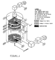
Figure 1 shows a partially cut away view of a fluid bed reactor according to an embodiment of the present invention; -
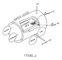
Figure 2 shows a view of a fluid bed reactor proof of concept device according to an embodiment of the present invention; and -
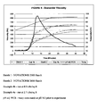
Figures 3-5 show charts related to trial runs carried out utilizing a fluid bed reactor proof of concept device of the type shown inFigure 2 . - Among those benefits and improvements that have been disclosed, other objects and advantages of this invention will become apparent from the following description taken in conjunction with the accompanying figures. The figures constitute a part of this specification and include illustrative embodiments of the present invention and illustrate various objects and features thereof.
- Detailed embodiments of the present invention are disclosed herein; however, it is to be understood that the disclosed embodiments are merely illustrative of the invention that may be embodied in various forms. In addition, each of the examples given in connection with the various embodiments of the invention are intended to be illustrative, and not restrictive. Further, the figures are not necessarily to scale, some features may be exaggerated to show details of particular components. In addition, any measurements, specifications and the like shown in the figures are intended to be illustrative, and not restrictive. Therefore, specific structural and functional details disclosed herein are not to be interpreted as limiting, but merely as a representative basis for teaching one skilled in the art to variously employ the present invention.
- Referring now to
Figure 1 (a partially cut away view), a fluid bed reactor 101 according to an embodiment of the present invention is shown. The fluid bed reactor 101 of this embodiment may comprise a housing 103 (shown here partially cut away) and at least onetray 105A-105D (of note, while four trays are shown in the Figure (and called-out with reference numerals), any number of trays (more trays or less trays) may, of course, be utilized - this is indicated by the three ellipses betweentray 105C andtray 105D). - As seen, in this embodiment the at least one
tray 105A-105D is disposed within thehousing 103. In one embodiment, there is a plurality of trays and in the shown embodiment the plurality oftrays 105A-105D are spaced vertically apart from one another. - Further, at least one motor (not shown) may be operatively connected to the at least one
tray 105A-105D to rotate the at least onetray 105A-105D. - In addition, at least one wiper may be provided (of note, while three
wipers 107A-107C are called-out with reference numerals, any desired number of wipers (e.g., one wiper per tray, a plurality of wipers per tray) may, of course, be utilized; of further note, no wiper is shown in this view fortray 105C, because in this illustrative view the wiper would be hidden from view at the back of thehousing 103, as the wipers may be at any radial position on the tray, either in the same position on each tray or in a different position from tray to tray). Each wiper may direct product on a top surface of a respective tray down through at least one radial slot in each respective tray as each respective tray is rotated by the motor (of note, while oneradial slot 115 is called-out with a reference numeral, any desired number of radial slots (e.g., one slot per tray, a plurality of slots per tray) may, of course, be utilized). While the wipers may be at any radial position, in one embodiment they are progressively oriented such that the product will may a substantially complete rotation on a tray prior to being directed through the radial slot. The wiper may also contribute, along with the fluidization, to the leveling and movement of the product. - Further, the at least one of the trays comprises a perforated material. In one example, one tray may comprises a perforated material. In another example, all of the trays may comprise a perforated material. In another example, less than all of the trays may comprise a perforated material. In another example, the perforated material may comprise less than the entire surface of a tray. In another example, the perforated material may comprise essentially the entire surface of a tray. Of note, in the view of
Figure 1 a perforated material comprises essentially the entire bottom surface of each tray, although only a portion of each perforated material is seen in this view (as a dark wedge) because product is depicted on top of each perforated material). - Further, each tray may have a raised lip or wall to retain the product on the tray. The lip or wall may be any height, but in one embodiment is the same height as the top of the wiper.
- The perforated material may permit a gas (e.g., heated dry supply fluid ("DSF")) to flow up out of the top surface of a tray and the flow of gas out of the top surface of the tray may at least partially fluidize product on the top surface of the tray.
- In one example, heated DSF may be provided by fan/
heater 109 via rotating DSF coupling 111 (additional heating may be provided by secondary fan/heater 113, if desired). - In another example, at least one heater may heat at least the housing (e.g., the exterior and/or the interior).
- In another example, at least one heater may heat at least some of the gas flowing up out of the top surface of the tray(s).
- In another example, a single motor may be utilized.
- In another example, a plurality of motors may be utilized.
- In another example, at least one of the wipers may be a stationary wiper.
- In another example, each of the wipers may be a stationary wiper.
- In another example, the perforated material may be sized to essentially prohibit product from passing through the perforations.
- In another example, the size of the perforations may be the same for each of the at least one tray.
- In another example in which there is a plurality of trays, the size of the perforations may be different for at least two of the trays.
- In another example, the perforations on a tray may all be of the same size.
- In another example, the perforations on a tray may be of different sizes.
- In another example, the gas may comprise air, dried gas, oxygen-enriched air, an inert gas, including in one embodiment nitrogen, steam (including in one embodiment superheated steam), and/or any combination thereof.
- In another example, the fluid bed reactor may further comprise at least one fan, wherein the gas may be caused to flow up out of the top surface of the tray by the fan.
- In another example, the fluid bed reactor may further comprise at least one heater.
- In another example, the heater may heat at least some of the gas flowing up out of the top surface of the tray.
- In another example, the heater may heat all of the gas flowing up out of the top surface of the tray.
- In another example in which there is a plurality of trays, the trays may be spaced vertically apart from one another along a common axis of rotation.
- In another example in which there is a plurality of trays, the vertical spacing between each of the plurality of trays may be the same for each of the plurality of trays.
- In another example in which there is a plurality of trays, the vertical spacing between each of the plurality of trays may be different for at least two of the plurality of trays.
- In another example, each of the at least one tray may be essentially circular.
- In another example, the top surface of each of the at least one tray may be essentially planar.
- In another example, the speed of rotation of each of the at least one tray may be the same.
- In another example in which there is a plurality of trays, the speed of rotation of at least two of the trays may be different.
- In another example, each of the at least one tray may have a single radial slot.
- In another example, each of the at least one tray may have a plurality of radial slots.
- In another example, each of the plurality of trays have the same number of slots and in another example in which there is a plurality of trays, at least two of the trays may have a different number of slots.
- In another example in which there is a plurality of radial slots, the spacing between the radial slots on the at least one tray may be the same.
- In another example in which there is a plurality of radial slots, the spacing between the radial slots on at least one tray may be different.
- In another example, the fluid bed reactor may further comprise at least one leveler, wherein each leveler may be associated with one of the at least one tray, and wherein each of the at least one leveler may maintain product on a top surface of a respective tray at a predetermined level.
- In another example, the predetermined level may be the same for each of the at least one leveler.
- In another example in which there is a plurality of levelers, the predetermined level may be different for at least two of the levelers.
- In another example, the at least one leveler may be a stationary leveler.
- In another example in which there is more than one leverler, each of the levelers may be a stationary leveler.
- In another example, each of the at least one tray may be disposed entirely within the housing.
- In another example, the perforated material perforation/mesh size may have a range of: 0.2 micron - 1000 microns; 5 microns - 500 microns; 25 microns - 250 microns; or 1 micron - 20 microns.
- In another example, the gas flow velocity may have a range of (may vary based on the size of the unit): 0.1 feet per hour - 3,000 feet per hour; 40 feet per hour - 300 feet per hour; 1200 feet per hour - 2400 feet per hour; 100 feet per hour - 1,000 feet per hour; 25 feet per hour - 500 feet per hour; or 1,000 feet per hour - 3,000 feet per hour.
- In another example, the product bed thickness may have a range of: 1/2" - 10"; 1.5" - 3"; or 1" - 5".
- In another example, the average product particle size may have a range of: .1 micron - 1000 microns; 1 micron - 250 microns; 25 microns - 100 microns; I micron - 25 microns; or < 10 microns.
- In another example, the tray diameter may have a range of 0.5' - 50'; 5' - 40'; 10' - 20'; or 15' - 25'.
- Referring now to
Figure 2 , a view of a fluid bed reactor proof of concept device 201 according to an embodiment of the present invention is shown. As seen in this Fig., a TRANS-FLOW plate 203 measuring approximately 12" x 18" was used with a 2"vertical wall 204 on the outside edge. The TRANS-FLOW plate 203 was installed in a heated vessel and supplied with a DSF, in this case an instrument air/nitrogen blend (of note, the fluid bed reactor proof of concept device 201 is partially cut away in this view (showing the interior with product on a perforated plate)). The flows, temperatures and pressures were monitored through the various experimental runs. - In this regard, several experiments were conducted regarding how the powder moves on the plate with respect to the DSF, and what would occur when heated. The work was done using the perforated plate and waxy corn starch at an initial moisture of 9.5%. One intent of the experiments was to determine the minimum quantity of DSF required in order to produce a suspended product bed. Of note, all examples, test runs, experiments and the like described herein are intended to be illustrative and not restrictive.
- With respect to determination of moisture when 1% or less, the following procedure was carried out - Five grams of powder was weighed onto a Cenco B-3 Digital moisture balance. The bulb power was set to 100% to heat the sample to between 135-140°C for 15 minutes. Weight percent moisture was determined by weight loss and reported directly by the moisture balance. Note, if moisture was above 1% moisture, the balance was run in automatic and stopped when there was no change in weight of the sample.
- Further, the DSF for the test runs was a mixture of nitrogen and compressed air. The liquid nitrogen was expanded to the gaseous state and contained less than 20 ppm oxygen and less than 18 ppm water from the assay supplied from the vendor. The compressed air was dried using a refrigerated drier and desiccant drier. The mixture used for the experiments was 62.5% nitrogen and 37.5% air by volume using rotometers.
- There were several unheated trials as follows:
- Examples 1a and 1b: Approximately 2 pounds of waxy corn starch was added to the test plate and evenly distributed across the plate using a straight edge. The compressed air used as the DSF was regulated between 10 and 20" WC. The DSF was supplied at 2 and 4 ft3/min pressure to the unit. In both cases, the product bed raised and cracked in the center, which allowed flow only through the cracks formed in the product bed. It was concluded that the method of distribution used packed the starch, and did not allow the DSF to flow uniformly through the product bed and between the particles.
- Example 2: A second test was conducted with the DSF flowing prior to the waxy corn starch being added at the same flow rates used in the first set of experiments (1a and 1b). After addition of the starch, the starch was not touched. During this experiment, the loading weights were increased up to 4-1/2 pounds. Using varying weights, the heights of the product bed varied from ¼" up to 1-1/2" high. The starch during these runs no longer packed when added, but flowed like a fluid, and leveled to the heights indicated above without additional interaction. Another visual observation was the surface did not appear to be moving like a traditional fluid bed which particles move from bottom to top and are in constant motion.
- Examples 3a and 3b: The third experiment outside the heated vessel was done to understand how the proof of concept device was fluidizing the starch. Keeping the DSF on from the start of the test the following was done. Waxy corn starch dyed red was added to the test plate for two tests (1) at the bottom prior to adding the waxy corn starch and (2) to the top after adding the waxy corn starch. In the first test, the dyed starch moved from the bottom to the top, but only during the addition of the waxy corn starch. The dyed starch remained at the walls of the test rig and did not flow across the test plate. The DSF to the product bed was shut down, and the test plate was cleaned and setup to run with the second test. During this second test, undyed waxy corn starch was added to the test plate with the DSF flowing. The dyed waxy corn starch was dispersed evenly over the bed. Migration of the waxy corn starch through the dyed starch was not seen. The top of the product bed remained stationary, and stayed the same red intensity as when the dyed starch was added. The duration of the tests was 30 minutes each. It was also noticed there was no starch build up and the plate was cleaned without residuals.
- Heated trials were carried out as follows:
- A heated vessel was retrofitted to accept the test plate as shown in
Figure 2 . This was done to determine if heating the DSF changed the operation of the poof of concept device, and its benefits. A heating unit for the DSF was not used for these experiments, but may be beneficial in additional trials. The vessel the test plate was installed in was heated. Waxy corn starch (4.4 lbs) was added to the test plate with DSF on prior to the addition of the waxy corn starch (the vessel was not heated at this point for safety reasons). The DSF used in this case was a mixture of nitrogen and compressed air. The liquid nitrogen was expanded to the gaseous state and contained less than 20 ppm oxygen and less than 18 ppm water from the assay supplied from the vendor. The compressed air was dried using a refrigerated drier followed by a desiccant drier. The mixture used for the experiment was 62.5% nitrogen and 37.5% air by volume. The vessel was closed and heated. Data from two of the runs is below:- o Example 4a: As seen in the chart of
Fig. 3 - The content pressure was about 1.5 psi during the heating and drying. The heating took about 6 hours for temperature to get to 300F. Moisture of the waxy corn starch decreased from 9.5% to 0.04%. - o Example 4b: As seen in the chart of
Fig. 4 - Contents pressure less than 1 psi during heating and drying. It took about 4 hours for temperature to get to 300F. Moisture of the waxy corn starch decreased from 9.5% to 0.5%. - o Brabender curves for 0.9 and 2.7 cfm/sq ft DSF flow (
Figs. 4 and3 , respectively) indicate properties of inhibited starches. The chart ofFig. 5 shows the level of inhibition compared to commercial starches, that is, the chart ofFig. 5 relates to Brabender viscosity curves for 0.9 and 2.7 cfm/sq ft DSF flow and commercial thermally inhibited starches produced by a commercial fluid bed reactor method. The products produced in the proof of concept device clearly indicate thermally inhibited products from the viscosity profiles. The starch with higher flow held for longer time indicates a more inhibited product, which would be expected based on experience with the commercial fluid bed reactor process..
- o Example 4a: As seen in the chart of
- Of note, various embodiments of the present invention may be used for processing starch, dextrins and/or converted starches.
- In another example, the present invention may be used in any desired starch process, including: dextrinization; starch drying; heat moisture treatment; preparation of soluble starch; or dry chemical modifications to starch (i.e. cross-linking and substitution).
- In another example, the present invention may be used in connection with the following processes: agglomerating, baking, blanching, calcinating, conditioning, cooling (e.g., evaporative), deactivating enzymes, dedusting, drying, fermenting, freeze drying, inert gas drying, pasteurizing, puffing, reacting, roasting, steam stripping, sterilizing, and/or any combination thereof.
- In another example, the present invention may be used in the food industry, dairy industry, nutraceuaticals industry, and/or any combination thereof.
- In another example, the present invention may be used in the food industry, dairy industry and/or nutraceuaticals industry in connection with derivatives, supplements, ingredients, end products, and/or any combination thereof.
- In another example, the present invention may be used in connection with the following products: beta carotene, breadcrumbs, calcium gluconate, cereals, cheese, coca beans, coffee, crumb, dextrose, GDL, grains, herbs and spices, KGA, lactitol, sorbitol, xylitol, lactose, licorice extrudate, lycopens, meat, nuts/peanuts, potato flakes, powdered milk, PUFA, rice, salt, sausage farce (rusk), seeds, soya, sugar, tea, tobacco, tomato pulp, vitamin A, vitamin C, and/or any combination thereof.
- In another example, the present invention may be used in connection with biomass processing, animal feed processing, inorganic waste processing, and/or any combination thereof.
- In another example, the present invention may be used in connection with the following products: blood meal, citrus peel, compost, domestic waste, fish feed, fish meal, manure, paper waste, potato residue, return brood, slaughter waste, sludge, wood, and/or any combination thereof.
- In another example, the present invention may be used in connection with bioplastics processing.
- In another example, the present invention may be used in connection with mineral processing.
- In another example, the present invention may be used in connection with the following products: aggregates, blast furnace slag, calcium carbonate, calumite, china clay, copper slag, ferrous metals, gypsum, iron slag, limestone, marble sand, non-ferrous metals, rock salt, sand, kaolin, and/or any combination thereof.
- In another example, the present invention may be used in connection with chemical processing.
- In another example, the present invention may be used in connection with the following products: ammonium sulphate, butyle rubber, calcium chloride, carboxyl methyl cellulose, chemicals, chomic acid, detergent powder, fertilizer, flame retardant, herbicides, hexamine, pena erythritol, pesticides, plastic granulate, polymers, potassium chloride, potassium sulphate, rubber pellets, salts, silica gel, sodium sulphate, twaron (Kevlar) pulp, vanadium oxide, Zn Pb granulate, aramide, and/or any combination thereof.
- Of note, any embodiments described herein may, of course, be implemented using any appropriate computer hardware and/or computer software. In this regard, those of ordinary skill in the art are well versed in the type of computer hardware that may be used (e.g., a mainframe, a mini-computer, a personal computer ("PC"), a network (e.g., an intranet and/or the Internet)), the type of computer programming techniques that may be used (e.g., object oriented programming), and the type of computer programming languages that may be used (e.g., C++, Basic). The aforementioned examples are, of course, illustrative and not restrictive.
- While a number of embodiments of the present invention have been described, it is understood that these embodiments are illustrative only, and not restrictive, and that many modifications may become apparent to those of ordinary skill in the art. For example, certain methods may have been described herein as being "computer implementable". In this regard it is noted that while such methods can be implemented using a computer, the methods do not necessarily have to be implemented using a computer. Also, to the extent that such methods are implemented using a computer, not every step must necessarily be implemented using a computer. Further, the housing may be heated, but need not necessarily be heated. Further, any heating may be carried out via conduction, convection and/or a combination thereof. Further still, any steps may be carried out in any desired order (and any desired steps may be added and/or any desired steps may be eliminated).
- The following embodiments are presented to further illustrate and explain the present invention and should not be taken as limiting in any regard.
- 1. A fluid bed reactor, comprising:
- a housing;
- at least one tray disposed within the housing,;
- at least one motor operatively connected to the at least one tray, wherein the motor rotates the at least one tray; and
- at least one wiper associated with at the at least one tray which directs product on a top surface of a respective tray down through at least one radial slot in each respective tray as each respective tray is rotated by the motor;
- wherein at least one of the trays at least partially comprises a perforated material;
- wherein the perforated material permits a gas to flow up out of the top surface of the tray; and
- wherein the flow of gas out of the top surface of the tray at least partially fluidizes product on the top surface of the tray.
- 2. The fluid bed reactor of
embodiment 1, wherein there is a plurality of trays spaced vertically apart from one another. - 3. The fluid bed reactor of
embodiment - 3. The fluid bed reactor of
embodiment 1, wherein a plurality of the trays comprise a perforated material. - 4. The fluid bed reactor of embodiment 3, wherein a size of the perforations is the same for each of the plurality of trays.
- 5. The fluid bed reactor of embodiment 3, wherein a size of the perforations is different for at least two of the plurality of trays.
- 6. The fluid bed reactor of
embodiment 1, wherein the gas comprises air, dried gas, oxygen-enriched air, nitrogen, another inert gas, steam, superheated steam, and/or any combination thereof. - 7. The fluid bed reactor of
embodiment 1, further comprising at least one fan, wherein the gas is caused to flow up out of the top surface of the tray by the fan. - 8. The fluid bed reactor of
embodiment 1, further comprising at least one heater, wherein the heater heats at least the housing. - 9. The fluid bed reactor of
embodiment 1, further comprising at least one heater, wherein the heater heats at least some of the gas flowing up out of the top surface of the tray. - 10. The fluid bed reactor of
embodiment 1, wherein the plurality of trays are spaced vertically apart from one another along a common axis of rotation. - 11. The fluid bed reactor of
embodiment 1, wherein a vertical spacing between each of the plurality of trays is the same for each of the plurality of trays. - 12. The fluid bed reactor of
embodiment 1, wherein a vertical spacing between each of the plurality of trays is different for at least two of the plurality of trays. - 13. The fluid bed reactor of
embodiment 1, wherein each of the plurality of trays is essentially circular. - 14. The fluid bed reactor of
embodiment 1, wherein the top surface of each of the plurality of trays is essentially planar. - 15. The fluid bed reactor of
embodiment 1, wherein a speed of rotation of each of the plurality of trays is the same. - 16. The fluid bed reactor of
embodiment 1, wherein each of the plurality of trays has a single radial slot. - 17. The fluid bed reactor of
embodiment 1, wherein each of the plurality of trays has a plurality of radial slots. - 18. The fluid bed reactor of embodiment 18, wherein a spacing between the plurality of radial slots on each of the plurality of trays is the same.
- 19. The fluid bed reactor of embodiment 18, wherein a spacing between the plurality of radial slots is different for at least two of the plurality of trays.
- 20. The fluid bed reactor of
embodiment 1, further comprising a plurality of levelers, wherein each of the plurality of levelers is associated with one of the plurality of trays, and wherein each of the plurality of levelers maintains product on a top surface of a respective tray at a predetermined level. - 21. The fluid bed reactor of embodiment 21, wherein the predetermined level is the same for each of the plurality of levelers.
- 22. The fluid bed reactor of embodiment 21, wherein the predetermined level is different for at least two of the plurality of levelers.
- 23. The fluid bed reactor of
embodiment 1, wherein each of the plurality of trays is disposed entirely within the housing. - In the claims, "comprising" or "comprises" is intended to mean "including the following elements but not excluding others"; "consisting of" or "consists of" is intended to mean "excluding more than trace amounts of other than the recited elements"; and "consisting essentially of" is intended to mean "excluding other elements of any essential significance to the claimed combination."
Claims (15)
- A fluid bed reactor, comprising:a housing;at least one tray disposed within the housing,;at least one motor operatively connected to the at least one tray, wherein the motor rotates the at least one tray; andat least one wiper associated with at the at least one tray which directs product on a top surface of a respective tray down through at least one radial slot in each respective tray as each respective tray is rotated by the motor;wherein at least one of the trays at least partially comprises a perforated material;wherein the perforated material permits a gas to flow up out of the top surface of the tray; andwherein the flow of gas out of the top surface of the tray at least partially fluidizes product on the top surface of the tray.
- The fluid bed reactor of claim 1, wherein there is a plurality of trays spaced vertically apart from one another.
- The fluid bed reactor of claim 1 or 2, wherein the perforated material is sized to essentially prohibit product from passing through the perforations.
- The fluid bed reactor of any one of claims 1-3, wherein a size of the perforations is the same for each of the plurality of trays.
- The fluid bed reactor of any one of claims 1-3, wherein a size of the perforations is different for at least two of the plurality of trays.
- The fluid bed reactor of any one of claims 1-5, wherein the gas comprises air, dried gas, oxygen-enriched air, nitrogen, another inert gas, steam, superheated steam, and/or any combination thereof.
- The fluid bed reactor of any one of claims 1-6, further comprising at least one fan, wherein the gas is caused to flow up out of the top surface of the tray by the fan.
- The fluid bed reactor of any one of claims 1-7, further comprising at least one heater, wherein the heater heats at least the housing.
- The fluid bed reactor of any one of claims 1-8, further comprising at least one heater, wherein the heater heats at least some of the gas flowing up out of the top surface of the tray.
- The fluid bed reactor of any one of claims 1-9, wherein the plurality of trays are spaced vertically apart from one another along a common axis of rotation.
- The fluid bed reactor of any one of claims 1-10, wherein each of the plurality of trays is essentially circular.
- The fluid bed reactor of any one of claims 1-11, wherein the top surface of each of the plurality of trays is essentially planar.
- The fluid bed reactor of any one of claims 1-12, wherein each of the plurality of trays has a single radial slot.
- The fluid bed reactor of any one of claims 1-12, wherein each of the plurality of trays has a plurality of radial slots.
- The fluid bed reactor of any one of claims 1-14, further comprising a plurality of levelers, wherein each of the plurality of levelers is associated with one of the plurality of trays, and wherein each of the plurality of levelers maintains product on a top surface of a respective tray at a predetermined level.
Applications Claiming Priority (2)
| Application Number | Priority Date | Filing Date | Title |
|---|---|---|---|
| US8743408P | 2008-08-08 | 2008-08-08 | |
| US12/437,190 US8034298B2 (en) | 2008-08-08 | 2009-05-07 | Fluid bed reactors and associated methods |
Publications (2)
| Publication Number | Publication Date |
|---|---|
| EP2153890A1 true EP2153890A1 (en) | 2010-02-17 |
| EP2153890B1 EP2153890B1 (en) | 2018-04-18 |
Family
ID=41168503
Family Applications (1)
| Application Number | Title | Priority Date | Filing Date |
|---|---|---|---|
| EP09010196.5A Active EP2153890B1 (en) | 2008-08-08 | 2009-08-06 | Fluid bed reactor |
Country Status (9)
| Country | Link |
|---|---|
| US (1) | US8034298B2 (en) |
| EP (1) | EP2153890B1 (en) |
| JP (1) | JP5663152B2 (en) |
| CN (1) | CN101703912B (en) |
| AU (1) | AU2009206181B2 (en) |
| BR (1) | BRPI0904296A2 (en) |
| CA (1) | CA2674176C (en) |
| MX (1) | MX2009008182A (en) |
| RU (1) | RU2502553C2 (en) |
Cited By (1)
| Publication number | Priority date | Publication date | Assignee | Title |
|---|---|---|---|---|
| WO2023049675A1 (en) | 2021-09-23 | 2023-03-30 | Cargill, Incorporated | Thermally inhibited, ozone treated starch or flour, and a method of manufacturing a thermally inhibited, ozone treated starch or flour |
Families Citing this family (19)
| Publication number | Priority date | Publication date | Assignee | Title |
|---|---|---|---|---|
| WO2011020528A1 (en) * | 2009-08-19 | 2011-02-24 | Cargill, Incorporated | Plasterboard panels and methods of making the same |
| US8534904B2 (en) * | 2010-03-10 | 2013-09-17 | Lord Ltd., Lp | Apparatus for restarting a gas-solids contactor |
| US8986785B2 (en) * | 2011-06-23 | 2015-03-24 | Surface Activation Technologies | Method and apparatus for continuous sulfonization of discrete article |
| US20130017039A1 (en) * | 2011-07-15 | 2013-01-17 | Wyssmont Company Inc. | Multi stream material processing apparatus |
| CN105157396B (en) * | 2013-01-04 | 2017-09-29 | 浙江红绿蓝纺织印染有限公司 | Continuous drying system and its method of work for the processing of three wastes synthetical recovery |
| CN103965366A (en) * | 2014-05-23 | 2014-08-06 | 李广志 | Mixed starch airflow dryer |
| US11512019B2 (en) * | 2016-08-10 | 2022-11-29 | Yoshino Gypsum Co., Ltd. | Apparatus and method for treating gypsum |
| CN111703137B (en) * | 2020-05-08 | 2022-01-11 | 上海继尔新材料科技有限公司 | Engineering material with flame retardant function |
| CN112354562B (en) * | 2020-11-25 | 2022-07-12 | 昆明理工大学 | Copper-containing catalyst and preparation method and application thereof |
| CN112985035A (en) * | 2020-12-24 | 2021-06-18 | 安徽都灵精密机械有限公司 | Grain is with high-efficient quick drying equipment based on humidity |
| CN112958029B (en) * | 2021-04-02 | 2024-08-02 | 华陆工程科技有限责任公司 | Synthetic reactor and N, N-dimethylacetamide synthesis system |
| CN113865271A (en) * | 2021-10-12 | 2021-12-31 | 常熟市春来机械有限公司 | Rotary drying tank |
| CN115540520A (en) * | 2022-05-18 | 2022-12-30 | 郭赛娇 | Drying equipment is used in preparation of high-efficient industrial enzyme |
| CN116123855B (en) * | 2022-11-09 | 2024-08-06 | 赣州有色冶金机械有限公司 | Scattering device for feeding of calciner |
| CN116878251B (en) * | 2023-08-10 | 2025-12-26 | 辽宁省粮食科学研究所 | Multi-parameter grain drying section multi-physics field simulation test device and control method |
| CN117299005A (en) * | 2023-10-11 | 2023-12-29 | 摩氢科技有限公司 | A carbon monoxide selective oxidation device and method |
| CN117968361B (en) * | 2024-03-28 | 2024-06-07 | 卫辉市卫新机械有限公司 | Drying and cooling device for cured powdery feed |
| CN118256334B (en) * | 2024-05-30 | 2025-06-24 | 山东中创健康科技集团有限公司 | Microbial additive fermentation air multistage filtration sterilization device |
| CN118602770B (en) * | 2024-08-05 | 2024-10-18 | 承德锦滦新材料科技有限公司 | A fluidized calcining furnace temperature control system and control method thereof |
Citations (12)
| Publication number | Priority date | Publication date | Assignee | Title |
|---|---|---|---|---|
| US2893851A (en) * | 1955-12-29 | 1959-07-07 | American Oil Co | Powdered catalyst contacting unit |
| DE1149336B (en) * | 1960-06-25 | 1963-05-30 | Ruhrchemie Ag | Countercurrent fluidized bed apparatus |
| DE2551578A1 (en) * | 1975-11-17 | 1977-05-26 | Werner Glatt | Granulator with rotary stirrer and upright cylindrical vessel - through which drying air flows vertically upwards |
| DE3828941A1 (en) * | 1988-05-07 | 1990-03-15 | Schumacher Walter | Process and apparatus for obtaining fats and oils, on the one hand, and coarse meal directly suitable as animal feed, on the other hand, from soya beans |
| EP0449398A2 (en) * | 1990-03-27 | 1991-10-02 | Grace GmbH | Process for the continuous treatment of very finely divided substances with gases in fluidized beds, and reactor for the implementation of this process |
| WO1994022764A1 (en) * | 1993-04-02 | 1994-10-13 | Valence Technology, Inc. | Apparatus and method for continuous synthesis of vanadium oxide |
| US5720822A (en) | 1995-06-07 | 1998-02-24 | National Starch And Chemical Investment Holding Corporation | Thermally-inhibited pregelatinized non-granular starches and flours and process for their production |
| US5725676A (en) | 1993-07-30 | 1998-03-10 | National Starch And Chemical Investment Holding Corporation | Thermally inhibited starches and flours and process for their production |
| US5910240A (en) * | 1996-12-23 | 1999-06-08 | Mobil Oil Corporation | FCC unit catalyst stripper |
| US5932017A (en) | 1993-07-30 | 1999-08-03 | National Starch And Chemical Investment Holding Corporation | Thermally-inhibited non-pregelatinized granular starches and flours and process for their preparation |
| US6451121B2 (en) | 1993-07-30 | 2002-09-17 | National Starch And Chemical Investment Holding Corporation | Thermally-inhibited non-pregelatinized granular starches and flours and process for their preparation |
| US8743409B2 (en) | 2010-09-06 | 2014-06-03 | Oki Data Corporation | Information processing apparatus and method of processing information |
Family Cites Families (22)
| Publication number | Priority date | Publication date | Assignee | Title |
|---|---|---|---|---|
| US3287823A (en) * | 1963-07-17 | 1966-11-29 | Vidali Livio | Disc drying apparatus for meal or powders of various kinds |
| US4236063A (en) * | 1978-06-22 | 1980-11-25 | Glucksman Dov Z | Dehydrator |
| US4839022A (en) * | 1984-12-03 | 1989-06-13 | Atlantic Richfield Company | Method and apparatus for treating oil-water-solids sludges and refinery waste streams |
| US4612183A (en) | 1985-02-25 | 1986-09-16 | Gte Products Corporation | Method of producing crystalline ammonium metatungstate |
| US4769923A (en) | 1987-09-08 | 1988-09-13 | Chang Yen Nien | Dryer for drying a product-laden air stream as spirally floated |
| CN2114124U (en) * | 1991-11-08 | 1992-08-26 | 中国科学院工程热物理研究所 | Multi-layer vertical fluid-bed dryer |
| JP3143309B2 (en) * | 1993-06-04 | 2001-03-07 | ホソカワミクロン株式会社 | Powder processing equipment |
| US5329020A (en) * | 1993-10-05 | 1994-07-12 | Monsanto Company | Preparation of polysuccinimide |
| US5602071A (en) * | 1994-05-26 | 1997-02-11 | Aero-Terra-Aqua Technologies Corporation | Bead for removing dissolved metal contaminants |
| JPH08196891A (en) * | 1995-01-30 | 1996-08-06 | A G Medical Kk | Granular product manufacturing method |
| US6395678B1 (en) * | 1999-09-01 | 2002-05-28 | Aero-Terra-Aqua Technologies Corporation | Bead and process for removing dissolved metal contaminants |
| US6609871B2 (en) | 2001-06-18 | 2003-08-26 | Young Industries, Inc. | System for handling bulk particulate materials |
| CN2519133Y (en) * | 2002-01-04 | 2002-10-30 | 上海帆旺电力设备制造有限公司 | Disk clinker-cooling machine |
| RU2207187C1 (en) * | 2002-02-04 | 2003-06-27 | Ивановский государственный химико-технологический университет | Multisectional fluidized bed apparatus |
| US6719500B2 (en) | 2002-08-20 | 2004-04-13 | The Young Industries, Inc. | System for pneumatically conveying bulk particulate materials |
| US6722822B2 (en) | 2002-08-20 | 2004-04-20 | The Young Industries, Inc. | System for pneumatically conveying bulk particulate materials |
| ES2232304B2 (en) * | 2003-11-07 | 2006-04-01 | Tecnologias Aplicadas Del Maiz, S.L. | PROCEDURE FOR THE FLAVOR OF CORN GRAINS. |
| BE1015976A3 (en) | 2004-04-14 | 2005-12-06 | Broqueville Axel De | Polymerization process in bed cataltytique vertical rotary fluidized. |
| US20060163118A1 (en) | 2005-01-26 | 2006-07-27 | Eastman Kodak Company | Particulate separation processes and apparatus |
| US7662422B2 (en) * | 2005-04-05 | 2010-02-16 | Furtaw Louis F | Crisp meat-based food snacks |
| US7446156B2 (en) | 2006-05-16 | 2008-11-04 | Westlake Longview Corporation | Swirling fluidized-bed reactors for olefin polymerization |
| CN101290185A (en) * | 2007-04-18 | 2008-10-22 | 沈开宇 | Automatic control vertical type drying-machine |
-
2009
- 2009-05-07 US US12/437,190 patent/US8034298B2/en active Active
- 2009-07-24 CA CA2674176A patent/CA2674176C/en not_active Expired - Fee Related
- 2009-07-30 MX MX2009008182A patent/MX2009008182A/en active IP Right Grant
- 2009-08-06 JP JP2009183090A patent/JP5663152B2/en not_active Expired - Fee Related
- 2009-08-06 AU AU2009206181A patent/AU2009206181B2/en not_active Ceased
- 2009-08-06 EP EP09010196.5A patent/EP2153890B1/en active Active
- 2009-08-07 BR BRPI0904296-2A patent/BRPI0904296A2/en not_active Application Discontinuation
- 2009-08-07 CN CN200910161888.6A patent/CN101703912B/en active Active
- 2009-08-07 RU RU2009130411/05A patent/RU2502553C2/en not_active IP Right Cessation
Patent Citations (15)
| Publication number | Priority date | Publication date | Assignee | Title |
|---|---|---|---|---|
| US2893851A (en) * | 1955-12-29 | 1959-07-07 | American Oil Co | Powdered catalyst contacting unit |
| DE1149336B (en) * | 1960-06-25 | 1963-05-30 | Ruhrchemie Ag | Countercurrent fluidized bed apparatus |
| DE2551578A1 (en) * | 1975-11-17 | 1977-05-26 | Werner Glatt | Granulator with rotary stirrer and upright cylindrical vessel - through which drying air flows vertically upwards |
| DE3828941A1 (en) * | 1988-05-07 | 1990-03-15 | Schumacher Walter | Process and apparatus for obtaining fats and oils, on the one hand, and coarse meal directly suitable as animal feed, on the other hand, from soya beans |
| EP0449398A2 (en) * | 1990-03-27 | 1991-10-02 | Grace GmbH | Process for the continuous treatment of very finely divided substances with gases in fluidized beds, and reactor for the implementation of this process |
| WO1994022764A1 (en) * | 1993-04-02 | 1994-10-13 | Valence Technology, Inc. | Apparatus and method for continuous synthesis of vanadium oxide |
| US5932017A (en) | 1993-07-30 | 1999-08-03 | National Starch And Chemical Investment Holding Corporation | Thermally-inhibited non-pregelatinized granular starches and flours and process for their preparation |
| US5725676A (en) | 1993-07-30 | 1998-03-10 | National Starch And Chemical Investment Holding Corporation | Thermally inhibited starches and flours and process for their production |
| US6231675B1 (en) | 1993-07-30 | 2001-05-15 | National Starch And Chemical Investment Holding Corporation | Thermally-inhibited non-pregelatinized granular starches and flours and process for their preparation |
| US6451121B2 (en) | 1993-07-30 | 2002-09-17 | National Starch And Chemical Investment Holding Corporation | Thermally-inhibited non-pregelatinized granular starches and flours and process for their preparation |
| US5720822A (en) | 1995-06-07 | 1998-02-24 | National Starch And Chemical Investment Holding Corporation | Thermally-inhibited pregelatinized non-granular starches and flours and process for their production |
| US6010574A (en) | 1995-06-07 | 2000-01-04 | National Starch And Chemical Investment Holding Corporation | Thermally-inhibited pregelatinized non-granular starches and flours and process for their production |
| US6261376B1 (en) | 1995-06-07 | 2001-07-17 | National Starch And Chemical Investment Holding Corporation | Thermally-Inhibited pregelatinized non-granular starches and flours |
| US5910240A (en) * | 1996-12-23 | 1999-06-08 | Mobil Oil Corporation | FCC unit catalyst stripper |
| US8743409B2 (en) | 2010-09-06 | 2014-06-03 | Oki Data Corporation | Information processing apparatus and method of processing information |
Cited By (1)
| Publication number | Priority date | Publication date | Assignee | Title |
|---|---|---|---|---|
| WO2023049675A1 (en) | 2021-09-23 | 2023-03-30 | Cargill, Incorporated | Thermally inhibited, ozone treated starch or flour, and a method of manufacturing a thermally inhibited, ozone treated starch or flour |
Also Published As
| Publication number | Publication date |
|---|---|
| CA2674176A1 (en) | 2010-02-08 |
| AU2009206181B2 (en) | 2013-03-28 |
| CA2674176C (en) | 2017-04-25 |
| CN101703912A (en) | 2010-05-12 |
| AU2009206181A1 (en) | 2010-02-25 |
| CN101703912B (en) | 2015-04-15 |
| RU2009130411A (en) | 2011-02-20 |
| JP2010042405A (en) | 2010-02-25 |
| US20100034709A1 (en) | 2010-02-11 |
| RU2502553C2 (en) | 2013-12-27 |
| JP5663152B2 (en) | 2015-02-04 |
| US8034298B2 (en) | 2011-10-11 |
| BRPI0904296A2 (en) | 2010-11-09 |
| MX2009008182A (en) | 2010-03-22 |
| EP2153890B1 (en) | 2018-04-18 |
Similar Documents
| Publication | Publication Date | Title |
|---|---|---|
| CA2674176C (en) | Fluid bed reactors and associated methods | |
| Hovmand | Fluidized bed drying | |
| Pallai et al. | Spouted bed drying | |
| Baker | Industrial drying of foods | |
| FI62958B (en) | ANORDING FOR FLUIDISERINGSPROCESSER | |
| Haron et al. | Recent advances in fluidized bed drying | |
| Levy et al. | 17 Pneumatic and Flash Drying | |
| Shilton et al. | Fluidization and its applications to food processing | |
| Oi et al. | Feasibility study for production of green banana flour in a spray dryer | |
| Masters | Spray dryers | |
| Lee et al. | Drying characteristics of starch in an inert medium fluidized bed | |
| Balasubramanian et al. | Drying of granular materials in circulating fluidized beds | |
| Telis-Romero et al. | Effect of apparent viscosity on the pressure drop during fluidized bed drying of soursop pulp | |
| Mujumdar et al. | Applications of vibration techniques for drying and agglomeration in food processing | |
| Saini et al. | Fluidized Bed Drying: Recent Developments and Applications | |
| Ruhyat et al. | Hydrodynamic study of drying on Qisthi Hindi using a Fluidized Bed Dryer | |
| Carsky | Design of a dryer for citrus peels | |
| JPS6152657B2 (en) | ||
| BAKU | 4 Fluidized bed dryers | |
| EP1250558B1 (en) | Method and apparatus for fluid-bed drying | |
| Kudra et al. | Novel drying technologies | |
| Hauhouot-O’Hara et al. | Technical notes: Angles of repose of ground marigold petals as a function of particle size, moisture content, and flow enhancer | |
| Abesekara et al. | Study on Fluidization Behaviour of Raw and Dry Sri Lankan Black Pepper | |
| KEPÇEOĞLU et al. | Determination Of The Ideal Flow Rate In Drying Of Table Salt | |
| Arsenijević et al. | Prediction of the particle circulation rate in a draft tube spouted bed suspension dryer |
Legal Events
| Date | Code | Title | Description |
|---|---|---|---|
| PUAI | Public reference made under article 153(3) epc to a published international application that has entered the european phase |
Free format text: ORIGINAL CODE: 0009012 |
|
| AK | Designated contracting states |
Kind code of ref document: A1 Designated state(s): AT BE BG CH CY CZ DE DK EE ES FI FR GB GR HR HU IE IS IT LI LT LU LV MC MK MT NL NO PL PT RO SE SI SK SM TR |
|
| AX | Request for extension of the european patent |
Extension state: AL BA RS |
|
| 17P | Request for examination filed |
Effective date: 20100817 |
|
| 17Q | First examination report despatched |
Effective date: 20100916 |
|
| RAP1 | Party data changed (applicant data changed or rights of an application transferred) |
Owner name: CORN PRODUCTS DEVELOPMENT INC. |
|
| GRAJ | Information related to disapproval of communication of intention to grant by the applicant or resumption of examination proceedings by the epo deleted |
Free format text: ORIGINAL CODE: EPIDOSDIGR1 |
|
| GRAP | Despatch of communication of intention to grant a patent |
Free format text: ORIGINAL CODE: EPIDOSNIGR1 |
|
| GRAP | Despatch of communication of intention to grant a patent |
Free format text: ORIGINAL CODE: EPIDOSNIGR1 |
|
| INTG | Intention to grant announced |
Effective date: 20171031 |
|
| GRAS | Grant fee paid |
Free format text: ORIGINAL CODE: EPIDOSNIGR3 |
|
| GRAA | (expected) grant |
Free format text: ORIGINAL CODE: 0009210 |
|
| AK | Designated contracting states |
Kind code of ref document: B1 Designated state(s): AT BE BG CH CY CZ DE DK EE ES FI FR GB GR HR HU IE IS IT LI LT LU LV MC MK MT NL NO PL PT RO SE SI SK SM TR |
|
| REG | Reference to a national code |
Ref country code: GB Ref legal event code: FG4D |
|
| REG | Reference to a national code |
Ref country code: CH Ref legal event code: EP |
|
| REG | Reference to a national code |
Ref country code: AT Ref legal event code: REF Ref document number: 989846 Country of ref document: AT Kind code of ref document: T Effective date: 20180515 |
|
| REG | Reference to a national code |
Ref country code: IE Ref legal event code: FG4D |
|
| REG | Reference to a national code |
Ref country code: DE Ref legal event code: R096 Ref document number: 602009051815 Country of ref document: DE |
|
| REG | Reference to a national code |
Ref country code: FR Ref legal event code: PLFP Year of fee payment: 10 |
|
| REG | Reference to a national code |
Ref country code: NL Ref legal event code: FP |
|
| REG | Reference to a national code |
Ref country code: SE Ref legal event code: TRGR |
|
| REG | Reference to a national code |
Ref country code: LT Ref legal event code: MG4D |
|
| PG25 | Lapsed in a contracting state [announced via postgrant information from national office to epo] |
Ref country code: NO Free format text: LAPSE BECAUSE OF FAILURE TO SUBMIT A TRANSLATION OF THE DESCRIPTION OR TO PAY THE FEE WITHIN THE PRESCRIBED TIME-LIMIT Effective date: 20180718 Ref country code: ES Free format text: LAPSE BECAUSE OF FAILURE TO SUBMIT A TRANSLATION OF THE DESCRIPTION OR TO PAY THE FEE WITHIN THE PRESCRIBED TIME-LIMIT Effective date: 20180418 Ref country code: BG Free format text: LAPSE BECAUSE OF FAILURE TO SUBMIT A TRANSLATION OF THE DESCRIPTION OR TO PAY THE FEE WITHIN THE PRESCRIBED TIME-LIMIT Effective date: 20180718 Ref country code: LT Free format text: LAPSE BECAUSE OF FAILURE TO SUBMIT A TRANSLATION OF THE DESCRIPTION OR TO PAY THE FEE WITHIN THE PRESCRIBED TIME-LIMIT Effective date: 20180418 Ref country code: FI Free format text: LAPSE BECAUSE OF FAILURE TO SUBMIT A TRANSLATION OF THE DESCRIPTION OR TO PAY THE FEE WITHIN THE PRESCRIBED TIME-LIMIT Effective date: 20180418 Ref country code: PL Free format text: LAPSE BECAUSE OF FAILURE TO SUBMIT A TRANSLATION OF THE DESCRIPTION OR TO PAY THE FEE WITHIN THE PRESCRIBED TIME-LIMIT Effective date: 20180418 |
|
| REG | Reference to a national code |
Ref country code: SK Ref legal event code: T3 Ref document number: E 27763 Country of ref document: SK |
|
| PG25 | Lapsed in a contracting state [announced via postgrant information from national office to epo] |
Ref country code: GR Free format text: LAPSE BECAUSE OF FAILURE TO SUBMIT A TRANSLATION OF THE DESCRIPTION OR TO PAY THE FEE WITHIN THE PRESCRIBED TIME-LIMIT Effective date: 20180719 Ref country code: LV Free format text: LAPSE BECAUSE OF FAILURE TO SUBMIT A TRANSLATION OF THE DESCRIPTION OR TO PAY THE FEE WITHIN THE PRESCRIBED TIME-LIMIT Effective date: 20180418 Ref country code: HR Free format text: LAPSE BECAUSE OF FAILURE TO SUBMIT A TRANSLATION OF THE DESCRIPTION OR TO PAY THE FEE WITHIN THE PRESCRIBED TIME-LIMIT Effective date: 20180418 |
|
| PG25 | Lapsed in a contracting state [announced via postgrant information from national office to epo] |
Ref country code: PT Free format text: LAPSE BECAUSE OF FAILURE TO SUBMIT A TRANSLATION OF THE DESCRIPTION OR TO PAY THE FEE WITHIN THE PRESCRIBED TIME-LIMIT Effective date: 20180820 |
|
| REG | Reference to a national code |
Ref country code: DE Ref legal event code: R097 Ref document number: 602009051815 Country of ref document: DE |
|
| PG25 | Lapsed in a contracting state [announced via postgrant information from national office to epo] |
Ref country code: DK Free format text: LAPSE BECAUSE OF FAILURE TO SUBMIT A TRANSLATION OF THE DESCRIPTION OR TO PAY THE FEE WITHIN THE PRESCRIBED TIME-LIMIT Effective date: 20180418 Ref country code: EE Free format text: LAPSE BECAUSE OF FAILURE TO SUBMIT A TRANSLATION OF THE DESCRIPTION OR TO PAY THE FEE WITHIN THE PRESCRIBED TIME-LIMIT Effective date: 20180418 Ref country code: CZ Free format text: LAPSE BECAUSE OF FAILURE TO SUBMIT A TRANSLATION OF THE DESCRIPTION OR TO PAY THE FEE WITHIN THE PRESCRIBED TIME-LIMIT Effective date: 20180418 Ref country code: RO Free format text: LAPSE BECAUSE OF FAILURE TO SUBMIT A TRANSLATION OF THE DESCRIPTION OR TO PAY THE FEE WITHIN THE PRESCRIBED TIME-LIMIT Effective date: 20180418 |
|
| PLBE | No opposition filed within time limit |
Free format text: ORIGINAL CODE: 0009261 |
|
| STAA | Information on the status of an ep patent application or granted ep patent |
Free format text: STATUS: NO OPPOSITION FILED WITHIN TIME LIMIT |
|
| PG25 | Lapsed in a contracting state [announced via postgrant information from national office to epo] |
Ref country code: IT Free format text: LAPSE BECAUSE OF FAILURE TO SUBMIT A TRANSLATION OF THE DESCRIPTION OR TO PAY THE FEE WITHIN THE PRESCRIBED TIME-LIMIT Effective date: 20180418 Ref country code: SM Free format text: LAPSE BECAUSE OF FAILURE TO SUBMIT A TRANSLATION OF THE DESCRIPTION OR TO PAY THE FEE WITHIN THE PRESCRIBED TIME-LIMIT Effective date: 20180418 |
|
| 26N | No opposition filed |
Effective date: 20190121 |
|
| PG25 | Lapsed in a contracting state [announced via postgrant information from national office to epo] |
Ref country code: MC Free format text: LAPSE BECAUSE OF FAILURE TO SUBMIT A TRANSLATION OF THE DESCRIPTION OR TO PAY THE FEE WITHIN THE PRESCRIBED TIME-LIMIT Effective date: 20180418 |
|
| REG | Reference to a national code |
Ref country code: CH Ref legal event code: PL |
|
| PG25 | Lapsed in a contracting state [announced via postgrant information from national office to epo] |
Ref country code: LU Free format text: LAPSE BECAUSE OF NON-PAYMENT OF DUE FEES Effective date: 20180806 Ref country code: LI Free format text: LAPSE BECAUSE OF NON-PAYMENT OF DUE FEES Effective date: 20180831 Ref country code: CH Free format text: LAPSE BECAUSE OF NON-PAYMENT OF DUE FEES Effective date: 20180831 |
|
| REG | Reference to a national code |
Ref country code: BE Ref legal event code: MM Effective date: 20180831 |
|
| REG | Reference to a national code |
Ref country code: IE Ref legal event code: MM4A |
|
| PG25 | Lapsed in a contracting state [announced via postgrant information from national office to epo] |
Ref country code: SI Free format text: LAPSE BECAUSE OF FAILURE TO SUBMIT A TRANSLATION OF THE DESCRIPTION OR TO PAY THE FEE WITHIN THE PRESCRIBED TIME-LIMIT Effective date: 20180418 |
|
| PG25 | Lapsed in a contracting state [announced via postgrant information from national office to epo] |
Ref country code: IE Free format text: LAPSE BECAUSE OF NON-PAYMENT OF DUE FEES Effective date: 20180806 |
|
| PG25 | Lapsed in a contracting state [announced via postgrant information from national office to epo] |
Ref country code: BE Free format text: LAPSE BECAUSE OF NON-PAYMENT OF DUE FEES Effective date: 20180831 |
|
| PG25 | Lapsed in a contracting state [announced via postgrant information from national office to epo] |
Ref country code: MT Free format text: LAPSE BECAUSE OF NON-PAYMENT OF DUE FEES Effective date: 20180806 |
|
| PG25 | Lapsed in a contracting state [announced via postgrant information from national office to epo] |
Ref country code: TR Free format text: LAPSE BECAUSE OF FAILURE TO SUBMIT A TRANSLATION OF THE DESCRIPTION OR TO PAY THE FEE WITHIN THE PRESCRIBED TIME-LIMIT Effective date: 20180418 |
|
| PG25 | Lapsed in a contracting state [announced via postgrant information from national office to epo] |
Ref country code: HU Free format text: LAPSE BECAUSE OF FAILURE TO SUBMIT A TRANSLATION OF THE DESCRIPTION OR TO PAY THE FEE WITHIN THE PRESCRIBED TIME-LIMIT; INVALID AB INITIO Effective date: 20090806 |
|
| PG25 | Lapsed in a contracting state [announced via postgrant information from national office to epo] |
Ref country code: CY Free format text: LAPSE BECAUSE OF FAILURE TO SUBMIT A TRANSLATION OF THE DESCRIPTION OR TO PAY THE FEE WITHIN THE PRESCRIBED TIME-LIMIT Effective date: 20180418 Ref country code: MK Free format text: LAPSE BECAUSE OF NON-PAYMENT OF DUE FEES Effective date: 20180418 |
|
| PG25 | Lapsed in a contracting state [announced via postgrant information from national office to epo] |
Ref country code: IS Free format text: LAPSE BECAUSE OF FAILURE TO SUBMIT A TRANSLATION OF THE DESCRIPTION OR TO PAY THE FEE WITHIN THE PRESCRIBED TIME-LIMIT Effective date: 20180818 |
|
| REG | Reference to a national code |
Ref country code: AT Ref legal event code: UEP Ref document number: 989846 Country of ref document: AT Kind code of ref document: T Effective date: 20180418 |
|
| P01 | Opt-out of the competence of the unified patent court (upc) registered |
Effective date: 20230530 |
|
| PGFP | Annual fee paid to national office [announced via postgrant information from national office to epo] |
Ref country code: NL Payment date: 20250826 Year of fee payment: 17 |
|
| PGFP | Annual fee paid to national office [announced via postgrant information from national office to epo] |
Ref country code: DE Payment date: 20250827 Year of fee payment: 17 |
|
| PGFP | Annual fee paid to national office [announced via postgrant information from national office to epo] |
Ref country code: GB Payment date: 20250827 Year of fee payment: 17 |
|
| PGFP | Annual fee paid to national office [announced via postgrant information from national office to epo] |
Ref country code: FR Payment date: 20250825 Year of fee payment: 17 Ref country code: AT Payment date: 20250827 Year of fee payment: 17 |
|
| PGFP | Annual fee paid to national office [announced via postgrant information from national office to epo] |
Ref country code: SE Payment date: 20250827 Year of fee payment: 17 |
|
| PGFP | Annual fee paid to national office [announced via postgrant information from national office to epo] |
Ref country code: SK Payment date: 20250718 Year of fee payment: 17 |