EP2153597B1 - Verfahren zur datenverarbeitung in einem drahtlosen kommunikationssystem - Google Patents
Verfahren zur datenverarbeitung in einem drahtlosen kommunikationssystem Download PDFInfo
- Publication number
- EP2153597B1 EP2153597B1 EP08741581A EP08741581A EP2153597B1 EP 2153597 B1 EP2153597 B1 EP 2153597B1 EP 08741581 A EP08741581 A EP 08741581A EP 08741581 A EP08741581 A EP 08741581A EP 2153597 B1 EP2153597 B1 EP 2153597B1
- Authority
- EP
- European Patent Office
- Prior art keywords
- lower layer
- data block
- indication information
- layer
- packet
- Prior art date
- Legal status (The legal status is an assumption and is not a legal conclusion. Google has not performed a legal analysis and makes no representation as to the accuracy of the status listed.)
- Not-in-force
Links
Images


Classifications
-
- H—ELECTRICITY
- H04—ELECTRIC COMMUNICATION TECHNIQUE
- H04W—WIRELESS COMMUNICATION NETWORKS
- H04W28/00—Network traffic management; Network resource management
- H04W28/02—Traffic management, e.g. flow control or congestion control
- H04W28/06—Optimizing the usage of the radio link, e.g. header compression, information sizing, discarding information
- H04W28/065—Optimizing the usage of the radio link, e.g. header compression, information sizing, discarding information using assembly or disassembly of packets
-
- H—ELECTRICITY
- H04—ELECTRIC COMMUNICATION TECHNIQUE
- H04L—TRANSMISSION OF DIGITAL INFORMATION, e.g. TELEGRAPHIC COMMUNICATION
- H04L69/00—Network arrangements, protocols or services independent of the application payload and not provided for in the other groups of this subclass
- H04L69/04—Protocols for data compression, e.g. ROHC
-
- H—ELECTRICITY
- H04—ELECTRIC COMMUNICATION TECHNIQUE
- H04W—WIRELESS COMMUNICATION NETWORKS
- H04W80/00—Wireless network protocols or protocol adaptations to wireless operation
- H04W80/04—Network layer protocols, e.g. mobile IP [Internet Protocol]
Definitions
- the present invention relates to a wireless communication system, and more particularly, to a method of data processing in a wireless communication system.
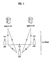
- FIG. 1 is a diagram illustrating a network structure of an E-UMTS (Evolved-Universal Mobile Telecommunications System).
- An E-UMTS is a system evolving from the conventional WCDMA (wideband code division multiple access) UMTS and its basic standardization is currently handled by the 3GPP (3 rd Generation Partnership Project).
- the E-UMTS can also be called an LTE (Long Term Evolution) system.
- an E-UTRAN (UMTS terrestrial radio access network) includes base stations (hereinafter, referred to as 'eNode B' or 'eNB'), wherein the respective eNBs are connected with each other through X2 interface. Also, each of eNBs is connected with a user equipment (UE) through a radio interface and connected with an EPC (Evolved Packet Core) through S1 interface.
- the EPC includes MME/SAE gateway (Mobility Management Entity/System Architecture Evolution gateway).
- Layers of a radio interface protocol between a UE and a network can be classified into a first layer L1, a second layer L2 and a third layer L3 based on three lower layers of OSI (open system interconnection) standard model widely known in communication systems.
- a physical layer belonging to the first layer L1 provides an information transfer service using a physical channel.
- a radio resource control (hereinafter, abbreviated as 'RRC') layer located at the third layer plays a role in controlling radio resources between the UE and the network.
- the RRC layer enables RRC messages to be exchanged between the UE and the network.
- the RRC layer may distributively be located at network nodes including Node B, an AG and the like, or may independently be located at either the Node B or the AG.
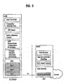
- FIG 2 is a schematic view illustrating an E-UTRAN (UMTS terrestrial radio access network).
- a hatching part represents functional entities of a user plane and a non-hatching part represents functional entities of a control plane.
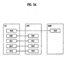
- FIG 3A and FIG 3B are diagrams illustrating a structure of a radio interface protocol between the user equipment (UE) and the E-UTRAN, in which FIG 3A is a schematic view of a control plane protocol and FIG 3B is a schematic view of a user plane protocol.
- a radio interface protocol horizontally includes a physical layer, a data link layer, and a network layer and vertically includes a user plane for data information transfer and a control plane for signaling transfer.
- the protocol layers in FIG 3A and FIG. 3B can be classified into L1 (first layer), L2 (second layer), and L3 (third layer) based on three lower layers of the open system interconnection (OSI) standard model widely known in the communications systems.
- OSI open system interconnection
- the physical layer as the first layer provides information transfer service to an upper layer using physical channels.
- the physical layer is connected to a medium access control (hereinafter, abbreviated as 'MAC') layer above the physical layer via a transport channel.
- 'MAC' medium access control
- Data are transferred between the medium access control layer and the physical layer via the transport channel.
- data are transferred between different physical layers, and more particularly, between one physical layer of a transmitting side and the other physical layer of a receiving side via the physical channel.
- the physical channel of the E-UMTS is modulated according to an orthogonal frequency division multiplexing (OFDM) scheme, and time and frequency are used as radio resources.
- OFDM orthogonal frequency division multiplexing
- the medium access control (hereinafter, abbreviated as 'MAC') layer of the second layer provides a service to a radio link control (hereinafter, abbreviated as 'RLC') layer above the MAC layer via a logical channel.
- the RLC layer of the second layer supports reliable data transfer.
- IP packets e.g., IPv4 or IPv6
- L2 a PDCP layer of the second layer
- a radio resource control (hereinafter, abbreviated as 'RRC') layer located on a lowest part of the third layer is defined in the control plane only and is associated with configuration, reconfiguration and release of radio bearers (hereinafter, abbreviated as 'RBs') to be in charge of controlling the logical, transport and physical channels.
- 'RBs' radio bearers
- the RB means a service provided by the second layer for the data transfer between the UE and the UTRAN.
- the PDCP layer included in the second layer will be described.
- the PDCP layer is connected with its upper layer, i.e., RRC layer or a user application layer, and is connected with its lower layer, i.e., RLC layer.
- Main functions carried out by the PDCP layer include a header compression function and a security function.
- the header compression function is used to enhance use efficiency of radio resources, and is advantageous in that the quantity of information to be transmitted from a radio terminal is decreased using common features of packets transmitted through a single Internet packet stream.
- Examples of the security function include ciphering and integrity check, and the security function is used to prevent data manipulation or monitoring by the third party from occurring.
- a robust header compression (ROHC) scheme is used to reduce header information of RTP (Real-time Transport Protocol)/UDP (User Datagram Protocol)/IP (Internet Protocol) packets.
- RTP Real-time Transport Protocol
- UDP User Datagram Protocol
- IP Internet Protocol
- RFC2507 another example of the header compression scheme includes RFC2507.
- the ROHC scheme is based on the fact that field values of packet headers in continuous packets belonging to one packet stream are almost constant. Accordingly, the ROHC scheme transmits a variable field not all the fields included in the packet headers.
- the entire header size of RTP/UDP/IP packets which are not compressed is 40 octet in case of IPv4 (IP version 4) and 60 octet in case of IPv6 (IP version 6) while size of a pure data part called payload is generally 15 ⁇ 20 octet. Accordingly, it is noted that transmission efficiency is very low as control information has a structure greater than that of user data to be actually transmitted. In this respect, if the header compression scheme is used, the quantity of control information can be reduced remarkably. For example, size of the header reduced by the ROHC scheme is only 1 octet to 3 octets.
- the ROHC scheme is divided into a uni-directional mode (hereinafter, abbreviated as 'U-mode'), a bi-directional optimistic mode (hereinafter, abbreviated as 'O-mode') and a bi-directional reliable mode (hereinafter, abbreviated as 'R-mode').
- 'U-mode uni-directional mode
- 'O-mode' bi-directional optimistic mode
- 'R-mode' bi-directional reliable mode
- the transmitting side performs uni-directional communication to the receiving side.
- the transmitting side performs bi-directional communication to transmit real-time packets and the receiving side transmits transmission status information to the transmitting side.
- the transmitting side transmits header compression packets of data and controls transmission of real-time traffic packets in response to ROHC status information (ACK or NACK) received from the receiving side.
- ROHC status information ACK or NACK
- a use purpose of the ROHC status information transferred from the receiving side to the transmitting side may depend on the mode.
- the ROHC scheme of the O-mode increases compression efficiency by mainly transmitting NACK related information, and the ROHC scheme of the R-mode supports robuster header compression scheme by using strict logic based on the ROHC status information.
- the ROHC status information can be called feedback information in a header compression procedure. In addition to the ROHC scheme, feedback information is also used in another header compression scheme.
- a compressor has there statuses, i.e., an entire context forming status, a dynamic context forming status, and an entire context perfect status.
- a type of a compression header packet is varied depending on each status, and its operation method is also varied depending on each status.
- the structure of a context includes a static context and a dynamic context.
- FIG. 4 is a diagram illustrating a status of an ROHC U-mode compressor according to the related art and its shift procedure.
- the entire context forming status means that the entire context has not been formed at all, or the entire context should be reconstructed due to its damage.
- the dynamic context forming status means that a dynamic context part of the entire context should be reconstructed due to its damage.
- the entire context perfect status means that the entire context is in a perfect status without damage.
- Each status is shifted to another status per period. At this time, the respective periods are different from one another. For example, a shift period from the entire context perfect status to the dynamic context forming status is much greater than that from the entire context perfect status to the entire context forming status.
- the document WO 2006/075820 A1 discloses a particular protocol layer of a transmitting side (transmitter) which initially receives service data units (SDUs) having the same priority through a single stream from an upper layer, processes these SDUs to generate protocol data unit (PDUs) having different priories, and uses respectively different transmission methods to transmit the generated PDUs over a radio interface in order to guarantee their respectively different quality of service requirements.
- the PDCP layer receives IP packets (namely, SDUs) through a single stream from an upper layer and performs header compression thereto to generate PDUs that include full header or compressed headers. Then, the PDCP layer transfers the generated PDUs to the RLC layer together with information indicating the priority for each PDU.
- the packet may be informed or the priorities may be divided into many levels such that packets including full headers are regarded as high priority and packets including compressed headers are regarded as low priority, or various other expressions (e.g., degrees of priority or importance) may be used.
- the document EP 1 372 310 A1 discloses an invention related to a system for communicating packet data using a variable header compression protocol, and an apparatus comprising a selector for selecting either an unacknowledged mode or an acknowledged mode in response to a header compression characteristic of the packet protocol applied to the packet data unit.
- the header compression is optional for PDCP PDUs and the actual header compression may be dynamically altered between packet data units for an ongoing session.
- a header compressor determines if header compression is to be applied to a current PDU. If so, the current PDU is compressed, and unacknowledged mode of the radio link protocol is selected. If header compression is not employed, acknowledged mode of the radio link is selected.
- a data block generated in the aforementioned PDCP layer according to the related art can be divided into various types depending on whether data included in the data block are transferred from an upper layer or generated directly in the PDCP layer. Also, the data block generated in the PDCP layer can be divided into various types depending on whether data transferred from an upper layer are user data or control data. Meanwhile, a lower layer which carries out data processing for each data block transferred from the PDCP layer needs to carry out data processing differently depending on a type of each data block generated in the PDCP layer. Accordingly, for efficiency of data processing in view of the lower layer, a method of identifying a type or feature of data blocks transferred from the PDCP layer is required.
- an object of the present invention is to provide a method of processing data efficiently in a wireless communication system, which substantially obviates one or more problems due to limitations and disadvantages of the related art.
- FIG 5 is a diagram illustrating functional entities included in PDCP layer and RLC layer of a transmitting side in E-UMTS. Although one entity corresponding to each function performed by the PDCP layer and RLC layer is illustrated in FIG 5 , two or more entities may be combined to constitute one entity.
- the PDCP layer receives upper layer data, i.e., PDCP SDU (Service Data Unit) from an upper layer such as an RRC layer or an application layer.
- PDCP SDU Service Data Unit
- the upper layer data transferred from the RRC layer is signaling information of a control plane for carrying out a function of the RRC layer
- the upper layer data transferred from the application layer is data of a user plane.
- a sequence number (SN) allocation entity 11 allocates a sequence number (SN) to the PDCP SDU transferred from the upper layer.
- a header compression entity 12 carries out a header compression function for the data of the user plane, i.e., the PDCP SDU, which are transferred from the upper layer. As described above, the header compression entity 12 can use an ROHC scheme as a compression scheme, and configures a header which includes a part not the entire of a field included in a header of a packet based on the fact that field values of respective packet headers are almost constant in continuous packets belonging to one packet stream.
- the header compression entity 12 does not carry out header compression for all PDCP SDUs, and periodically or non-periodically transmits full headers to a receiving side, wherein the full headers are not compressed.
- the receiving side reconstructs compressed headers based on the received full headers.
- the header compression function is not applied to the upper layer data transferred from the RRC layer.
- the header compression entity 12 generates a control packet which is not related with the PDCP SDU transferred from the upper layer, i.e., which does not include upper layer data.
- the control packet is related with carrying out the function of the PDCP layer, and includes control information generated by the header compression entity.
- An example of the control information includes feedback information or status information for the PDCP PDU received from the receiving side.
- the feedback information includes information related with header compression of the PDCP PDU received from the receiving side.
- the status information can include information as to whether the PDCP PDU received from the receiving side has been successfully received or whether retransmission is required.
- the control information can include other control information in addition to the feedback information or the status information.
- FIG. 6 is a diagram illustrating a procedure of transferring control information generated in the header compression entity 12 to the receiving side.
- first control information B is transmitted from the left to the right, and means response information of compression packet streams, i.e., 'Stream C,' which are transmitted from the right to the left, such as feedback information or status information.
- Second control information D is transmitted from the right to the left, and means response information of compression packet streams, i.e., 'Stream A,' which are transmitted from the left to the right.
- the first control information B transferred in the same direction has no relation with the PDCP SDUs transferred through 'Point E' and is related with a stream of packets transferred to the PDCP layer through 'Point F' and connected to 'Stream C.
- the first control information and the second control information are related with management of context information. Accordingly, the control information is information generated regardless of PDCP SDUs transferred from the upper layer in view of the PDCP layer of the transmitting side. In this case, a sequence number is not allocated by the SN allocation entity.
- an integrity check entity 13 carries out integrity protection for the PDCP SDUs, which include control plane data, i.e., the PDCP SDUs transferred from the RRC layer.
- the integrity check can be carried out in such a manner that a field called MAC-1 (Message Authentication Code for Integrity Protection) is affixed to PDCP PDU which will be transmitted.
- MAC-1 Message Authentication Code for Integrity Protection
- a ciphering entity 14 carries out ciphering for a compression packet and RRC message, wherein the compression packet has undergone header compression by the header compression entity 12 and the RRC message has undergone integrity protection by the integrity check entity 13.
- Data (PLAINTEXT BLOCK) is ciphered through bit operation between ciphering parameters and MASK generated by a specific ciphering algorithm to form CIPHERTEXT BLOCK.
- the CIPHERTEXT BLOCK is transmitted to the receiving side through a radio period, and the receiving side which has received the CIPHERTEXT BLOCK generates the same MASK through the ciphering algorithm used at the transmitting side to recover the original PLAINTEXT BLOCK.
- the ciphering parameters mean CK, COUNT-C, BEARER, DIRECTION, LENGTH, etc, wherein COUNT-C is related with the sequence number of the PDCP SDU where ciphering is carried out, and is varied depending on time.
- COUNT-C is related with the sequence number of the PDCP SDU where ciphering is carried out, and is varied depending on time.
- the control packet to which the sequence number is not allocated is are not ciphered.
- a PDCP header addition entity 15 generates PDCP PDU by adding PDCP header to the data block transferred from the header compression entity 12 or the ciphering entity 14.
- the PDCP PDU can be divided into three types. The first type is a PDCP PDU which includes upper layer data of the control plane, wherein the upper layer data is transferred from the RRC layer.
- the second type is a PDCP PDU which includes upper layer data of the user plane, wherein the upper layer data is transferred from the application layer which is the upper layer.
- the third type is a PDCP PDU which includes the control packet generated by the header compression entity 12. As illustrated in FIG. 5 , since ciphering is carried out by the ciphering entity 14 before header addition, ciphering is not carried out in the header of the PDCP PDU regardless of the type of the PDCP PDU.
- FIG 7 is a diagram illustrating an example of a data format of the PDCP PDU which includes the upper layer data of the control plane.
- the header of the PDCP PDU illustrated in FIG 7 includes PDCP SN field which includes a sequence number.
- 'R' field means a reserved bit.
- MAC-1 field includes a message authentication code added for integrity protection by the integrity check entity 13.
- FIG. 8 is a diagram illustrating an example of a data format of the PDCP PDU which includes the upper layer data of the user plane.
- the header of the PDCP PDU illustrated in FIG 8 includes a D/C field and a PDCP SN field.
- the D/C field includes information indicating whether a corresponding PDCP PDU includes user data or control information.
- the D/C field includes an indicator which indicates that a corresponding PDCP PDU includes user data.
- FIG 9A and FIG 9B are diagrams illustrating examples of data formats of PDCP PDUs which include control information generated in the PDCP layer not an upper layer, wherein the PDCP PDUs include different types of control information.
- the PDCP PDUs illustrated in FIG 9A and FIG 9B include a D/C field and a PDU type field in common.
- the D/C field includes an indicator which indicates that a corresponding PDCP PDU includes control information.
- the PDU type field includes information indicating a type of control information included in the corresponding PDCP PDU. Since FIG 9A and FIG 9B include different types of control information, the respective PDU Type fields include different types of information. Accordingly, the receiving side can identify what type of control information is included in the corresponding PDCP PDU, by using the information included in the PDU Type field.
- the control information included in the PDCP PDU of FIG 9A corresponds to an interspersed ROHC feedback packet.
- the interspersed ROHC feedback packet is generated by the header compression entity of FIG 5 , have no relation with the PDCP SDU transferred from the upper layer, and include feedback information of the PDCP PDU received from the receiving side.
- the information included in the PDCP PDU of FIG. 9B is status report information, and includes information indicating whether a plurality of PDCP PDUs received from the receiving side have been successfully received.
- the status report information can include information as to whether the plurality of PDCP PDUs received from the receiving side have been successfully received, in a bit map type.
- PDCP PDU which includes such another type of control information can be configured.
- the PDU Type field included in the header of the corresponding PDCP PDU includes information different from the PDU Type field included in the PDCP PDUs of FIG 9A and FIG. 9B , so that the PDU Type fields can be identified from each other.
- An example of another type of control information generated in the PDCP layer includes status report information for reporting reception acknowledgement information of PDCP SDUs after carrying out handover.
- each PDCP PDU generated in the PDCP layer is transferred to the RLC layer which is a lower layer.
- the PDCP layer transfers indication information to the RLC layer, wherein the indication information is related with a method of data processing in the RLC layer of each PDCP PDU.
- the indication information can be included in a specific primitive used for information exchange between the PDCP layer and the RLC layer and then can be transferred from the PDCP layer to the RLC layer.
- the indication information can be included in a corresponding PDCP PDU, for example, a specific field of a header of the corresponding PDCP PDU, and then can be transferred from the PDCP layer to the RLC layer.
- the indication information is information related with the method of data processing in the RLC layer of each PDCP PDU, and can include at least one of segmentation information indicating whether the corresponding PDCP PDU can be segmented in the RLC layer and then can included in different data blocks, i.e., RLC PDUs, connection information indicating whether the corresponding PDCP PDU can be concatenated with another PDCP PDU in the RLC layer and then can be included in one RLC PDU, information indicating whether the corresponding PDCP PDU includes a control packet or a compression packet, type information indicating a type of the corresponding PDCP PDU, and transfer information indicating whether the corresponding PDCP PDU is emergency data or non-emergency data.
- the RLC layer carries out data processing according to the indication information for at least one PDCP PDU (RLC SDU) transferred from the PDCP layer.
- the RLC layer can be divided into three modes. The first mode is a transparent mode (TM). This TM RLC entity serves to transfer the RLC SDU transferred from the PDCP layer to the lower layer without separate data processing.
- the second mode is an unacknowledged mode (UM). This UM RLC entity serves to segment/concatenate RLC SDU and generate RLC PDU through header addition.
- the third mode is an acknowledged mode (AM). This AM RLC entity serves to carry out functions related with retransmission of RLC SDU in addition to the functions of the UM mode.
- the RLC layer illustrated in FIG 5 is an example of a configuration of the UM RLC entity.
- a transmission buffer 16 stores PDCP PDUs (RLC SDUs) transferred from the PDCP layer.
- a segmentation/concatenation entity 17 carries out segmentation for the RLC SDU output from the transmission buffer 16, or carries out concatenation for the RLC SDU output from the transmission buffer 16 with two or more RLC SDUs, as occasion demands.
- An RLC header addition entity 18 adds an RLC header to the RLC SDU segmented or concatenated by the segmentation/concatenation entity 17 to generate RLC PDU.
- the generated RLC PDU is transferred to the lower layer.
- the TM RLC entity includes a transmission buffer only, and the AM RLC entity additionally includes a retransmission entity and RLC control entity in addition to elements of the UM RLC entity.
- the segmentation/concatenation entity 17 of the RLC layer divides the corresponding PDCP PDU into two or more.
- the RLC header addition entity 18 adds RLC header to each of the divided parts to generate RLC PDU. If the indication information includes segmentation information indicating that the PDCP PDU transferred from the PDCP layer cannot be divided, the RLC layer does not divide the corresponding PDCP PDU.
- the indication information includes concatenation information indicating that the PDCP PDU transferred from the PDCP layer can be concatenated with another PDCP PDU in the RLC layer and can be included in one RLC PDU
- the segmentation/concatenation entity 17 of the RLC layer concatenates the corresponding PDCP PDU with at least one PDCP PDU
- the RLC header addition entity 18 adds a header to the concatenated PDCP PDUs to generate one RLC PDU.
- the RLC layer does not concatenate the corresponding PDCP PDU with another PDCP PDU and generates RLC PDU including the corresponding PDCP PDU. In this case, if there is a space in the corresponding RLC PDU, the space can be filled with padding.
- a type of the corresponding PDCP PDU can be considered. For example, if the corresponding PDCP PDU includes a compression packet, it can be segmented or can be concatenated with another PDCP PDU which includes a compression packet. Also, if the corresponding PDCP PDU includes a control packet or other control information, it can be included in one RLC PDU without being segmented or concatenated with another PDCP PDU.
- the RLC layer carries out a data process procedure previously set for the corresponding PDCP PDU in accordance with the type of the corresponding PDCP PDU.
- the PDCP PDU which includes control information or a control packet can be set so as not to carry out segmentation or concatenation, and the PDCP PDU which includes a compression packet can be set to carry out segmentation or concatenation if necessary.
- the PDCP PDU which includes control information or a control packet can be set to carry out concatenation with another PDCP PDU, although not be set to carry out segmentation.
- the RLC layer can directly transfer the corresponding PDCP PDU to the lower layer without separate data processing procedure. If the indication information includes transfer information indicating that the PDCP PDU transferred from the PDCP layer is non-emergency data, the RLC layer transfers the corresponding PDCP PDU to the lower layer after data processing procedure which is previously set.
- the RLC header addition entity 18 of the RLC layer adds RLC header to the RLC SDU to generate RLC PDU, it can include at least one indicator in the RLC header, wherein the indicator indicates information related with a feature of the corresponding RLC SDU.
- the indicator can indicate a type of the PDCP PDU included in the RLC PDU, i.e., whether the corresponding PDCP PDU includes a control packet or control information, or a compression packet.
- the indicator can indicate whether the control packet is RoHC feedback information or status report information.
- the indicator can indicate whether the RLC SDU included in the corresponding RLC PDU includes information generated in the RLC layer or information related with the PDCP layer. Also, the indicator can indicate whether the RLC SDU included in the corresponding RLC PDU includes information related with PDCP SDU, or information not related with PDCP SDU.
- the RLC header addition entity 18 of the RLC layer adds RLC header to the RLC SDU to generate RLC PDU, it can include an indicator in the RLC header, wherein the indicator indicates information as to whether a sequence number has been included in the corresponding RLC PDU, information as to whether a sequence number has been included in PDCP PDU included in the corresponding RLC PDU, or information as to whether the PDCP PDU included in the corresponding RLC PDU is related with a specific sequence number.
- the RLC PDU can include an indicator indicating whether the PDCP PDU included in the corresponding RLC PDU is prohibited to carry out segmentation or whether the corresponding PDCP PDU should immediately be transferred to the PDCP layer of the receiving side.
- the RLC PDU can include an indicator indicating whether the PDCP PDU included in the corresponding RLC PDU corresponds to a full packet.
- the RLC layer of the receiving side can carry out different data processing procedures in accordance with at least one indicator included in the header of the RLC PDU transmitted from the transmitting side. For example, if the at least one indicator indicates that the PDCP PDU included in the corresponding RLC PDU includes control information or a control packet, or indicates that the full packet has been included in the corresponding PDCP PDU, the RLC layer of the receiving side can be set to transfer the corresponding PDCP PDU to the upper layer regardless of the sequence number. Even in case that the at least one indicator indicates that the PDCP PDU included in the corresponding RLC PDU should immediately be transferred to the upper layer, the RLC layer immediately transfers the corresponding PDCP PDU to the upper layer regardless of the sequence number.
- the embodiments according to the present invention may be implemented by various means, for example, hardware, firmware, software, or their combination. If the of the present invention may be implemented by one or more application specific integrated circuits (ASICs), digital signal processors (DSPs), digital signal processing devices (DSPDs), programmable logic devices (PLDs), filed programmable gate arrays (FPGAs), processors, controllers, microcontrollers, microprocessors, etc.
- ASICs application specific integrated circuits
- DSPs digital signal processors
- DSPDs digital signal processing devices
- PLDs programmable logic devices
- FPGAs field programmable gate arrays
- processors controllers, microcontrollers, microprocessors, etc.
- the method of transmitting and receiving data in the wireless communication system according to the embodiment of the present invention may be implemented by a type of a module, a procedure, or a function, which performs functions or operations described as above.
- a software code may be stored in a memory unit and then may be driven by a processor.
- the memory unit may be located inside or outside the processor to transmit and receive data to and from the processor through various means which are well known.
- the present invention can be applied to a wireless communication system such as a mobile communication system and a wireless Internet system.
Claims (8)
- Verfahren zum Übertragen eines Datenblocks an eine empfangende Seite durch einen Sender in einem drahtlosen Kommunikationssystem, wobei das Verfahren umfasst:Generieren eines Steuerpakets und/oder eines Datenpakets, das zumindest einen Teil eines von einer Oberschicht übertragenen Oberschicht-Datenblocks enthält, durch eine erste Unterschicht mit einer Headerkomprimierungsfunktion;Generieren eines ersten Unterschicht-Datenblocks, der jedes des generierten mindestens einen Pakets enthält, durch die erste Unterschicht, um den ersten Unterschicht-Datenblock an eine zweite Unterschicht unter der ersten Unterschicht zu übertragen, undwobei das Verfahren dadurch gekennzeichnet ist, dass:das Steuerpaket Steuerinformationen enthält, die nicht mit dem Oberschicht-Datenblock verknüpft sind, und das Verfahren umfasst:Übertragen erster Anzeigeinformationen von der ersten Unterschicht an die zweite Unterschicht, wobei die ersten Anzeigeinformationen anzeigen, ob der erste Unterschicht-Datenblock das Steuerpaket oder das Datenpaket enthält;Übertragen erster Typanzeigeinformationen von der ersten Unterschicht an die zweite Unterschicht, wenn die ersten Anzeigeinformationen anzeigen, dass der erste Unterschicht-Datenblock das Steuerpaket enthält, wobei die ersten Typanzeigeinformationen einen Typ des im ersten Unterschicht-Datenblock enthaltenen Steuerpakets anzeigen;Generieren eines zweiten Unterschicht-Datenblocks auf Grundlage der ersten Anzeigeinformationen und/oder der ersten Typanzeigeinformationen durch die zweite Unterschicht, wobei der zweite Unterschicht-Datenblock zumindest einen Teil des von der ersten Unterschicht übertragenen ersten Unterschicht-Datenblocks enthält;Übertragen zweiter Anzeigeinformationen, die anzeigen, ob der erste Unterschicht-Datenblock, der zumindest teilweise im zweiten Unterschicht-Datenblock enthalten ist, das Steuerpaket oder das Datenpaket enthält, an die empfangende Seite; undÜbertragen zweiter Typanzeigeinformationen an die empfangende Seite, wenn die zweiten Anzeigeinformationen anzeigen, dass der erste Unterschicht-Datenblock, der zumindest teilweise im zweiten Unterschicht-Datenblock enthalten ist, das Steuerpakets enthält, wobei die zweiten Typanzeigeinformationen einen Typ des im ersten Unterschicht-Datenblock im zweiten Unterschicht-Datenblock enthaltenen Steuerpakets anzeigen,wobei die zweiten Anzeigeinformationen und die zweiten Typanzeigeinformationen in einem Header des zweiten unteren Datenblocks enthalten sind und an die empfangende Seite übertragen werden.
- Verfahren nach Anspruch 1, wobei die ersten Typanzeigeinformationen anzeigen, ob das im ersten Unterschichtblock enthaltene Steuerpaket Headerkomprimierungsrückmeldeinformationen oder Statusberichtinformationen enthält,
wobei die Headerkomprimierungsrückmeldeinformationen Rückmeldeinformationen für einen von der empfangenen Seite empfangenen Datenblock anzeigen und die Statusberichtinformationen anzeigen, ob ein von der empfangenden Seite übertragener Datenblock erfolgreich empfangen wurde. - Verfahren nach Anspruch 2, wobei die Rückmeldeinformationen Informationen in Bezug auf die Headerkomprimierung des von der empfangenden Seite empfangenen Datenblocks enthalten.
- Verfahren nach einem der Ansprüche 2 oder 3, wobei die zweiten Typanzeigeinformationen anzeigen, ob das im zweiten Unterschicht-Datenblock enthaltene Steuerpaket die Statusberichtinformationen enthält.
- Verfahren nach einem der Ansprüche 1 bis 4, wobei die ersten Anzeigeinformationen und die ersten Typanzeigeinformationen in einem Header des ersten unteren Datenblocks enthalten sind und an die zweite Unterschicht übertragen werden.
- Verfahren nach einem der Ansprüche 1 bis 5, wobei das durch die erste Unterschicht generierte Datenpaket ein durch die Headerkomprimierungsfunktion für den Oberschicht-Datenblock generiertes komprimiertes Paket ist.
- Verfahren nach einem der Ansprüche 1 bis 6, wobei die zweite Unterschicht auf Grundlage der ersten Anzeigeinformationen und/oder der ersten Typanzeigeinformationen bestimmt, ob der erste Unterschicht-Datenblock in der zweiten Unterschicht segmentierbar ist und anschließend in verschiedenen Datenblöcken enthalten sein kann und/oder ob der erste Unterschicht-Datenblock mit einem anderen ersten Unterschicht-Datenblock verknüpfbar ist und anschließend in einem Datenblock enthalten sein kann.
- Verfahren nach einem der Ansprüche 1 bis 7, wobei die erste Unterschicht das Datenpaket, das den Oberschicht-Datenblocks zumindest teilweise enthält, verschlüsselt und die ersten Anzeigeinformationen dem verschlüsselten Datenpaket hinzufügt, um den ersten Unterschicht-Datenblock zu generieren, und den ersten unteren Datenblock, der das verschlüsselte Datenpaket enthält, an die zweite Unterschicht überträgt; und
die erste Unterschicht das Steuerpaket nicht verschlüsselt und die ersten und zweiten Anzeigeinformationen dem Steuerpaket hinzufügt, um den ersten Unterschicht-Datenblock, der das unverschlüsselte Steuerpaket enthält, zu generieren, und den ersten Unterschicht-Datenblock, der das unverschlüsselte Steuerpaket enthält, an die zweite Unterschicht überträgt.
Applications Claiming Priority (3)
| Application Number | Priority Date | Filing Date | Title |
|---|---|---|---|
| US91591707P | 2007-05-03 | 2007-05-03 | |
| KR1020080040615A KR101456000B1 (ko) | 2007-05-03 | 2008-04-30 | 무선 통신 시스템에서의 데이터 처리 방법 |
| PCT/KR2008/002482 WO2008136598A1 (en) | 2007-05-03 | 2008-05-01 | Method of data processing in a wireless communication system |
Publications (3)
| Publication Number | Publication Date |
|---|---|
| EP2153597A1 EP2153597A1 (de) | 2010-02-17 |
| EP2153597A4 EP2153597A4 (de) | 2010-11-10 |
| EP2153597B1 true EP2153597B1 (de) | 2013-04-03 |
Family
ID=39943676
Family Applications (1)
| Application Number | Title | Priority Date | Filing Date |
|---|---|---|---|
| EP08741581A Not-in-force EP2153597B1 (de) | 2007-05-03 | 2008-05-01 | Verfahren zur datenverarbeitung in einem drahtlosen kommunikationssystem |
Country Status (3)
| Country | Link |
|---|---|
| US (1) | US8005115B2 (de) |
| EP (1) | EP2153597B1 (de) |
| WO (1) | WO2008136598A1 (de) |
Families Citing this family (9)
| Publication number | Priority date | Publication date | Assignee | Title |
|---|---|---|---|---|
| WO2009018318A2 (en) * | 2007-08-02 | 2009-02-05 | Interdigital Patent Holdings, Inc. | Packet data convergence protocol procedures |
| KR101392697B1 (ko) | 2007-08-10 | 2014-05-19 | 엘지전자 주식회사 | 이동통신 시스템에서의 보안 오류 검출방법 및 장치 |
| AR068651A1 (es) * | 2007-10-01 | 2009-11-25 | Inter Digital Patent Holding I | Metodo y aparato para mejorar varias operaciones pdcp y capa 2 |
| JP4952586B2 (ja) * | 2008-01-07 | 2012-06-13 | 富士通株式会社 | パケットデータの廃棄方法、無線通信装置、移動通信システム |
| KR101831448B1 (ko) | 2010-02-02 | 2018-02-26 | 엘지전자 주식회사 | 이동 통신 시스템에서 pdcp 기능을 선택적으로 적용하는 방법 |
| CA2931501C (en) * | 2013-12-03 | 2019-02-26 | Lg Electronics Inc. | Apparatus for processing at least one pdu (protocol data unit) in a broadcast system, method for processing at least one pdu (protocol data unit) in a broadcast system |
| CN107404734B (zh) * | 2016-05-18 | 2022-08-19 | 中兴通讯股份有限公司 | 数据发送方法、装置及系统 |
| US10910325B2 (en) * | 2017-05-29 | 2021-02-02 | Intel Corporation | Integrated circuit packages with conductive element having cavities housing electrically connected embedded components |
| US20190297532A1 (en) * | 2018-03-20 | 2019-09-26 | Nokia Technologies Oy | Application Notifications From Network For Throughput And Flow Control Adaptation |
Family Cites Families (97)
| Publication number | Priority date | Publication date | Assignee | Title |
|---|---|---|---|---|
| US6157833A (en) | 1997-11-14 | 2000-12-05 | Motorola, Inc. | Method for reducing status reporting in a wireless communication systems |
| US6321171B1 (en) * | 1998-04-03 | 2001-11-20 | Tektronix, Inc. | Electronic measurement instrument probe accessory offset, gain, and linearity correction method |
| JP3844877B2 (ja) | 1998-04-08 | 2006-11-15 | パイオニア株式会社 | ストリーム変換装置 |
| KR100348289B1 (ko) | 1998-05-04 | 2002-09-18 | 엘지정보통신주식회사 | 이동통신시스템에있어서방송형단문서비스실행방법 |
| US6611519B1 (en) | 1998-08-19 | 2003-08-26 | Swxtch The Rules, Llc | Layer one switching in a packet, cell, or frame-based network |
| US6131030A (en) | 1998-08-19 | 2000-10-10 | Telefonaktiebolaget Lm Ericsson | System network and method for the transference of cell handover information |
| KR20000024783A (ko) | 1998-10-01 | 2000-05-06 | 정선종 | 다중 반송파 부호분할다중접속방식의 기지국 시스템, 그의 다중코드 파형 발생방법 및 이를 이용한 이동통신 시스템 |
| CN1265671C (zh) | 1998-11-04 | 2006-07-19 | 西门子公司 | 在移动无线电系统中进行数据传输的方法、移动站和基站 |
| US6353628B1 (en) | 1998-12-15 | 2002-03-05 | Nortel Networks Limited | Apparatus, method and system having reduced power consumption in a multi-carrier wireline environment |
| FI114077B (fi) | 1999-03-10 | 2004-07-30 | Nokia Corp | Tunnuksen varausmenetelmä |
| US7245707B1 (en) | 1999-03-26 | 2007-07-17 | Chan Hark C | Data network based telephone messaging system |
| JP3928777B2 (ja) | 1999-05-26 | 2007-06-13 | ノキア コーポレイション | ランダムアクセス制御方法及びシステム |
| ES2281707T3 (es) | 1999-07-07 | 2007-10-01 | Samsung Electronics Co., Ltd. | Aparato y procedimiento de asignacion de canales para un canal comun por paquetes en un sistema de comunicaciones moviles wcdma. |
| FI112304B (fi) | 2000-02-14 | 2003-11-14 | Nokia Corp | Datapakettien numerointi pakettivälitteisessä tiedonsiirrossa |
| EP1148689B1 (de) | 2000-04-18 | 2006-06-14 | Motorola, Inc. | Herunterladen von Webseiten |
| JP3771420B2 (ja) | 2000-04-19 | 2006-04-26 | 富士通株式会社 | 交換局装置,基地局制御装置及びマルチコール通話呼数変更方法 |
| JP3413833B2 (ja) | 2000-05-18 | 2003-06-09 | 日本電気株式会社 | アクセス制御方法と基地局装置 |
| US6557030B1 (en) | 2000-05-31 | 2003-04-29 | Prediwave Corp. | Systems and methods for providing video-on-demand services for broadcasting systems |
| US6708040B1 (en) | 2000-06-19 | 2004-03-16 | Rajiv Laroia | Link level support of wireless data |
| JP4453168B2 (ja) | 2000-06-23 | 2010-04-21 | 日本電気株式会社 | 移動通信制御方法、セルラシステム、移動局、基地局及び基地局制御装置 |
| US6681115B1 (en) | 2000-08-14 | 2004-01-20 | Vesuvius Inc. | Communique subscriber handoff between a narrowcast cellular communication network and a point-to-point cellular communication network |
| KR100447162B1 (ko) | 2000-08-19 | 2004-09-04 | 엘지전자 주식회사 | 래디오 링크 콘트롤(rlc)에서 프로토콜 데이터 유닛(pdu) 정보의 길이 지시자(li) 처리방법 |
| EP1325590B1 (de) | 2000-10-09 | 2005-07-06 | Siemens Aktiengesellschaft | Verfahren zur übertragung von datenpaketen über eine luftschnittstelle eines mobilfunksystems |
| KR20020030367A (ko) | 2000-10-17 | 2002-04-25 | 오길록 | 이동통신시스템에서 임의접속채널의 전송방법 |
| US7116641B2 (en) | 2000-11-15 | 2006-10-03 | Lg Electronics Inc. | Multicast and broadcast transmission method and apparatus of a CDMA mobile communication network |
| WO2002041540A1 (en) | 2000-11-17 | 2002-05-23 | Samsung Electronics Co., Ltd | Apparatus and method for measuring propagation delay in an nb-tdd cdma mobile communication system |
| SE0101846D0 (sv) | 2001-05-22 | 2001-05-22 | Ericsson Telefon Ab L M | Method and system of retransmission |
| FI118244B (fi) | 2001-06-27 | 2007-08-31 | Nokia Corp | Otsikkokenttien kompressiotunnisteen välittäminen datapakettiyhteydellä |
| KR100802618B1 (ko) | 2001-07-07 | 2008-02-13 | 엘지전자 주식회사 | 무선통신시스템에서 이동국 식별자 설정방법 및 장치 |
| US7515616B2 (en) | 2001-11-24 | 2009-04-07 | Lg Electronics Inc. | Packet transmission scheduling technique |
| DE60229482D1 (de) | 2001-11-24 | 2008-12-04 | Lg Electronics Inc | Verfahren zur Übertragung von Paketdaten in komprimierter Form in einem Kommunikationssystem |
| KR100883063B1 (ko) | 2002-02-16 | 2009-02-10 | 엘지전자 주식회사 | 문맥 재할당 방법 |
| US7177658B2 (en) | 2002-05-06 | 2007-02-13 | Qualcomm, Incorporated | Multi-media broadcast and multicast service (MBMS) in a wireless communications system |
| EP1372310A1 (de) * | 2002-06-12 | 2003-12-17 | Motorola, Inc. | Vorrichtung und Verfahren zur Datenübertragung mit Header-Kompression |
| KR100893070B1 (ko) | 2002-09-19 | 2009-04-17 | 엘지전자 주식회사 | 무선통신 시스템의 멀티캐스트 서비스 제공 및 수신 방법, 그리고 그 장치 |
| KR100926707B1 (ko) * | 2002-11-05 | 2009-11-17 | 엘지전자 주식회사 | 이동통신 시스템의 데이터 통신방법 |
| US20040180675A1 (en) | 2002-11-06 | 2004-09-16 | Samsung Electronics Co., Ltd. | Method for transmitting and receiving control messages in a mobile communication system providing MBMS service |
| GB0225903D0 (en) | 2002-11-07 | 2002-12-11 | Siemens Ag | Method for uplink access transmissions in a radio communication system |
| US7649865B2 (en) | 2002-11-08 | 2010-01-19 | Nokia Corporation | Service-activation based state switching |
| JP4173484B2 (ja) | 2002-11-19 | 2008-10-29 | 株式会社エヌ・ティ・ティ・ドコモ | 移動通信システム、集線装置、無線基地局、移動局及び通信方法 |
| KR100488801B1 (ko) | 2002-12-04 | 2005-05-12 | 한국전자통신연구원 | 직교 주파수 분할 다중화 기반의 버스트한 패킷 데이터전송 방법 및 그 장치 |
| KR100483007B1 (ko) | 2002-12-24 | 2005-04-18 | 한국전자통신연구원 | 차세대 이동통신 시스템에서의 핸드오버 방법 |
| KR20040064867A (ko) | 2003-01-10 | 2004-07-21 | 삼성전자주식회사 | 이동통신 시스템에서 역방향 메시지의 전송 구간을제공하는 방법 |
| KR100976140B1 (ko) | 2003-04-03 | 2010-08-16 | 퀄컴 인코포레이티드 | 멀티캐스트 멀티미디어 방송 서비스를 제공하는 이동 통신 시스템에서 호출 방법 |
| KR101002908B1 (ko) | 2003-07-14 | 2010-12-21 | 삼성전자주식회사 | 무선 패킷 데이터 통신 시스템에서 다중 서비스 지원을 위한 프로토콜 데이터 유닛 생성 방법 및 장치 |
| KR100651405B1 (ko) | 2003-07-24 | 2006-11-29 | 삼성전자주식회사 | 이동통신 시스템에서 멀티미디어 브로드캐스트/멀티캐스트 서비스의 제어 정보 송수신 장치 및 방법 |
| KR20050019388A (ko) | 2003-08-19 | 2005-03-03 | 엘지전자 주식회사 | 멀티미디어 방송 및 멀티캐스트 서비스를 위한 패킷데이터와 관련 제어정보를 송수신하는 방법 |
| KR100964679B1 (ko) | 2003-08-19 | 2010-06-22 | 엘지전자 주식회사 | 멀티미디어 방송 멀티 캐스트서비스에서 무선자원제어연결 모드 단말을 집계하는 방법 |
| US20050094670A1 (en) * | 2003-08-20 | 2005-05-05 | Samsung Electronics Co., Ltd. | Method for acquiring header compression context in user equipment for receiving packet data service |
| KR100689543B1 (ko) | 2003-08-26 | 2007-03-02 | 삼성전자주식회사 | 이동통신 시스템에서 상향링크 패킷 전송을 위한 스케쥴링 요청 방법 및 장치 |
| CA2502860C (en) | 2003-09-16 | 2011-01-25 | Samsung Electronics Co., Ltd. | Method and system for providing status information for broadcast/multicast service in a mobile communication system |
| US7330699B2 (en) | 2003-10-07 | 2008-02-12 | Lucent Technologies Inc. | Method and apparatus for providing multicast services in a wireless communication environment |
| AU2003280552A1 (en) * | 2003-10-30 | 2005-05-19 | Utstarcom (China) Co. Ltd. | A device and method on real time ip packet wireless transfer using compress header technique |
| US7881191B2 (en) | 2003-11-12 | 2011-02-01 | Utstarcom (China) Co. Ltd. | Method and apparatus for downlink multi-channel packet combined scheduling in mobile communication system |
| US7263085B2 (en) | 2003-12-29 | 2007-08-28 | Motorola, Inc. | Apparatus and method for controlling connection status |
| KR100595646B1 (ko) | 2004-01-09 | 2006-07-03 | 엘지전자 주식회사 | Mbms서비스를 제공하는 무선통신 시스템 |
| KR100595644B1 (ko) | 2004-01-09 | 2006-07-03 | 엘지전자 주식회사 | 이동통신 시스템에서 점대다 서비스를 위한 통지 지시자 수신방법 |
| KR101048256B1 (ko) * | 2004-03-31 | 2011-07-08 | 엘지전자 주식회사 | 이동통신 시스템의 중요도에 따른 데이터 전송방법 |
| GB0408423D0 (en) | 2004-04-15 | 2004-05-19 | Nokia Corp | Transmission of services in a wireless communications network |
| JP4433891B2 (ja) | 2004-06-11 | 2010-03-17 | 日本電気株式会社 | 発呼規制方法と通信制御方法並びにシステム |
| JP2006067115A (ja) | 2004-08-25 | 2006-03-09 | Nippon Telegr & Teleph Corp <Ntt> | 無線パケット通信方法および無線パケット通信システム |
| EP1641302B1 (de) | 2004-09-27 | 2009-07-01 | Panasonic Corporation | Anonymer Aufwärtsrichtungsmessbericht in einem drahtlosen Kommunikationssystem |
| KR101141650B1 (ko) | 2004-09-30 | 2012-05-17 | 엘지전자 주식회사 | 매체접속제어 계층에서의 데이터 처리 방법 및 이동통신용단말 |
| KR100663279B1 (ko) | 2004-09-30 | 2007-01-02 | 삼성전자주식회사 | 이동통신시스템의 무선 채널에서 음성 서비스를 지원하는방법 및 장치 |
| ATE350866T1 (de) | 2004-10-21 | 2007-01-15 | Cit Alcatel | Verfahren zum bereitstellen eines mbms-dienstes in einem drahtlosen kommunikationssystem |
| US20060094478A1 (en) | 2004-11-04 | 2006-05-04 | Lg Electronics Inc. | Mobile power handling method and apparatus |
| US7551596B2 (en) | 2004-11-09 | 2009-06-23 | Samsung Electronics Co., Ltd. | Method and apparatus for signaling control information of uplink packet data service in mobile communication system |
| KR100983277B1 (ko) | 2005-02-15 | 2010-09-24 | 엘지전자 주식회사 | 멀티미디어 방송/멀티캐스트 서비스 송수신 방법 |
| CN101151924B (zh) | 2005-03-29 | 2010-12-22 | Lg电子株式会社 | 无线移动通信系统中产生下层数据块的方法以及设备 |
| JP2006295725A (ja) | 2005-04-13 | 2006-10-26 | Ntt Docomo Inc | 移動局、基地局および移動通信システム並びに通信制御方法 |
| US7756050B2 (en) * | 2005-04-29 | 2010-07-13 | Alcatel-Lucent Usa Inc. | Method to provide unequal error protection and unequal error detection for internet protocol applications |
| KR100913900B1 (ko) | 2005-05-04 | 2009-08-26 | 삼성전자주식회사 | 이동통신 시스템에서 미리 정의된 길이 지시자를 이용해서 패킷 데이터를 송수신하는 방법 및 장치 |
| DE602006000886T2 (de) | 2005-05-04 | 2009-07-30 | Samsung Electronics Co., Ltd., Suwon | Verfahren und Vorrichtung zum Melden einer Inter-Frequenzmessung unter Verwendung einer RACH-Nachricht in einem Kommunikationssystem |
| US8385878B2 (en) | 2005-06-28 | 2013-02-26 | Qualcomm Incorporated | Systems, methods, and apparatus for activity control in a wireless communications device |
| WO2007023364A1 (en) | 2005-08-23 | 2007-03-01 | Nokia Corporation | Radio link control unacknowledged mode header optimization |
| US8094595B2 (en) | 2005-08-26 | 2012-01-10 | Qualcomm Incorporated | Method and apparatus for packet communications in wireless systems |
| US8489128B2 (en) | 2005-10-31 | 2013-07-16 | Qualcomm Incorporated | Efficient transmission on a shared data channel for wireless communication |
| KR20070047124A (ko) | 2005-11-01 | 2007-05-04 | 엘지전자 주식회사 | 무선 자원에 관한 정보를 송수신하는 방법 |
| US20070155389A1 (en) | 2005-12-31 | 2007-07-05 | Lucent Technologies, Inc. | Method for controlling header compression during handoffs in a wireless system |
| KR101203841B1 (ko) | 2006-01-05 | 2012-11-21 | 엘지전자 주식회사 | 무선 통신 시스템에서의 페이징 메시지 전송 및 수신 방법 |
| KR101265628B1 (ko) | 2006-01-05 | 2013-05-22 | 엘지전자 주식회사 | 이동 통신 시스템에서의 무선 자원 스케줄링 방법 |
| US8000305B2 (en) | 2006-01-17 | 2011-08-16 | Motorola Mobility, Inc. | Preamble sequencing for random access channel in a communication system |
| EP1982476B1 (de) | 2006-01-20 | 2018-09-05 | Nokia Technologies Oy | Direktzugriffsprozedur mit verbesserter abdeckung |
| WO2007130637A2 (en) * | 2006-05-05 | 2007-11-15 | Interdigital Technology Corporation | Apparatuses for performing ciphering with pdcp layer sequence number or by pdcp entities |
| WO2007133034A2 (en) | 2006-05-13 | 2007-11-22 | Lg Electronics Inc. | Method of performing procedures for initial network entry and handover in a broadband wireless access system |
| US7916675B2 (en) | 2006-06-20 | 2011-03-29 | Nokia Corporation | Method and system for providing interim discontinuous reception/transmission |
| US7760676B2 (en) | 2006-06-20 | 2010-07-20 | Intel Corporation | Adaptive DRX cycle length based on available battery power |
| US8818321B2 (en) | 2006-06-20 | 2014-08-26 | Nokia Corporation | Method and system for providing reply-controlled discontinuous reception |
| CN101473564B (zh) | 2006-06-20 | 2013-03-27 | 英特尔公司 | 用于附加资源请求的随机接入请求扩展 |
| US8295243B2 (en) | 2006-08-21 | 2012-10-23 | Qualcomm Incorporated | Method and apparatus for random access in an orthogonal multiple-access communication system |
| WO2008024282A2 (en) * | 2006-08-21 | 2008-02-28 | Interdigital Technology Corporation | Method and apparatus for controlling arq and harq transmissions and retranmissions in a wireless communication system |
| US8948206B2 (en) | 2006-08-31 | 2015-02-03 | Telefonaktiebolaget Lm Ericsson (Publ) | Inclusion of quality of service indication in header compression channel |
| AU2007318106A1 (en) | 2006-10-27 | 2008-05-15 | Interdigital Technology Corporation | Method and apparatus for enhancing discontinuous reception in wireless systems |
| US7957360B2 (en) | 2007-01-09 | 2011-06-07 | Motorola Mobility, Inc. | Method and system for the support of a long DRX in an LTE—active state in a wireless network |
| KR101293812B1 (ko) | 2007-01-30 | 2013-08-06 | 인터디지탈 테크날러지 코포레이션 | Lte_활성 모드에서 암묵적 drx 싸이클 길이 조절 제어 |
| WO2008111684A1 (en) | 2007-03-12 | 2008-09-18 | Sharp Kabushiki Kaisha | Flexible user equipment-specified discontinuous reception |
| US8504046B2 (en) | 2008-01-03 | 2013-08-06 | Telefonaktiebolaget Lm Ericsson (Publ) | Fast radio link recovery after handover failure |
-
2008
- 2008-05-01 US US12/451,255 patent/US8005115B2/en not_active Expired - Fee Related
- 2008-05-01 WO PCT/KR2008/002482 patent/WO2008136598A1/en active Application Filing
- 2008-05-01 EP EP08741581A patent/EP2153597B1/de not_active Not-in-force
Also Published As
| Publication number | Publication date |
|---|---|
| EP2153597A1 (de) | 2010-02-17 |
| EP2153597A4 (de) | 2010-11-10 |
| WO2008136598A1 (en) | 2008-11-13 |
| US8005115B2 (en) | 2011-08-23 |
| US20100118890A1 (en) | 2010-05-13 |
Similar Documents
| Publication | Publication Date | Title |
|---|---|---|
| US9131003B2 (en) | Method of transmitting data in a wireless communication system | |
| US10433206B2 (en) | Method for processing radio protocol in mobile telecommunications system and transmitter of mobile telecommunications | |
| EP2153597B1 (de) | Verfahren zur datenverarbeitung in einem drahtlosen kommunikationssystem | |
| US8416678B2 (en) | Method for repairing an error depending on a radio bearer type | |
| KR101456000B1 (ko) | 무선 통신 시스템에서의 데이터 처리 방법 |
Legal Events
| Date | Code | Title | Description |
|---|---|---|---|
| PUAI | Public reference made under article 153(3) epc to a published international application that has entered the european phase |
Free format text: ORIGINAL CODE: 0009012 |
|
| 17P | Request for examination filed |
Effective date: 20091201 |
|
| AK | Designated contracting states |
Kind code of ref document: A1 Designated state(s): AT BE BG CH CY CZ DE DK EE ES FI FR GB GR HR HU IE IS IT LI LT LU LV MC MT NL NO PL PT RO SE SI SK TR |
|
| AX | Request for extension of the european patent |
Extension state: AL BA MK RS |
|
| RIN1 | Information on inventor provided before grant (corrected) |
Inventor name: YI, SEUNG JUNE Inventor name: CHUN, SUNG DUCK Inventor name: LEE, YOUNG DAE Inventor name: PARK, SUNG JUN |
|
| DAX | Request for extension of the european patent (deleted) | ||
| A4 | Supplementary search report drawn up and despatched |
Effective date: 20101011 |
|
| RIC1 | Information provided on ipc code assigned before grant |
Ipc: H04L 29/08 20060101ALI20101005BHEP Ipc: H04L 12/58 20060101AFI20081126BHEP |
|
| 17Q | First examination report despatched |
Effective date: 20110624 |
|
| REG | Reference to a national code |
Ref country code: DE Ref legal event code: R079 Ref document number: 602008023452 Country of ref document: DE Free format text: PREVIOUS MAIN CLASS: H04L0012580000 Ipc: H04L0029060000 |
|
| GRAP | Despatch of communication of intention to grant a patent |
Free format text: ORIGINAL CODE: EPIDOSNIGR1 |
|
| RIC1 | Information provided on ipc code assigned before grant |
Ipc: H04L 29/08 20060101ALI20121011BHEP Ipc: H04W 80/02 20090101ALI20121011BHEP Ipc: H04L 29/06 20060101AFI20121011BHEP Ipc: H04W 28/06 20090101ALI20121011BHEP |
|
| GRAS | Grant fee paid |
Free format text: ORIGINAL CODE: EPIDOSNIGR3 |
|
| GRAA | (expected) grant |
Free format text: ORIGINAL CODE: 0009210 |
|
| AK | Designated contracting states |
Kind code of ref document: B1 Designated state(s): AT BE BG CH CY CZ DE DK EE ES FI FR GB GR HR HU IE IS IT LI LT LU LV MC MT NL NO PL PT RO SE SI SK TR |
|
| REG | Reference to a national code |
Ref country code: GB Ref legal event code: FG4D |
|
| REG | Reference to a national code |
Ref country code: AT Ref legal event code: REF Ref document number: 605332 Country of ref document: AT Kind code of ref document: T Effective date: 20130415 Ref country code: CH Ref legal event code: EP |
|
| REG | Reference to a national code |
Ref country code: IE Ref legal event code: FG4D |
|
| REG | Reference to a national code |
Ref country code: DE Ref legal event code: R096 Ref document number: 602008023452 Country of ref document: DE Effective date: 20130529 |
|
| REG | Reference to a national code |
Ref country code: AT Ref legal event code: MK05 Ref document number: 605332 Country of ref document: AT Kind code of ref document: T Effective date: 20130403 |
|
| PG25 | Lapsed in a contracting state [announced via postgrant information from national office to epo] |
Ref country code: SI Free format text: LAPSE BECAUSE OF FAILURE TO SUBMIT A TRANSLATION OF THE DESCRIPTION OR TO PAY THE FEE WITHIN THE PRESCRIBED TIME-LIMIT Effective date: 20130403 |
|
| REG | Reference to a national code |
Ref country code: NL Ref legal event code: VDEP Effective date: 20130403 |
|
| REG | Reference to a national code |
Ref country code: LT Ref legal event code: MG4D |
|
| PG25 | Lapsed in a contracting state [announced via postgrant information from national office to epo] |
Ref country code: NL Free format text: LAPSE BECAUSE OF FAILURE TO SUBMIT A TRANSLATION OF THE DESCRIPTION OR TO PAY THE FEE WITHIN THE PRESCRIBED TIME-LIMIT Effective date: 20130403 Ref country code: ES Free format text: LAPSE BECAUSE OF FAILURE TO SUBMIT A TRANSLATION OF THE DESCRIPTION OR TO PAY THE FEE WITHIN THE PRESCRIBED TIME-LIMIT Effective date: 20130714 Ref country code: IS Free format text: LAPSE BECAUSE OF FAILURE TO SUBMIT A TRANSLATION OF THE DESCRIPTION OR TO PAY THE FEE WITHIN THE PRESCRIBED TIME-LIMIT Effective date: 20130803 Ref country code: BE Free format text: LAPSE BECAUSE OF FAILURE TO SUBMIT A TRANSLATION OF THE DESCRIPTION OR TO PAY THE FEE WITHIN THE PRESCRIBED TIME-LIMIT Effective date: 20130403 Ref country code: NO Free format text: LAPSE BECAUSE OF FAILURE TO SUBMIT A TRANSLATION OF THE DESCRIPTION OR TO PAY THE FEE WITHIN THE PRESCRIBED TIME-LIMIT Effective date: 20130703 Ref country code: SE Free format text: LAPSE BECAUSE OF FAILURE TO SUBMIT A TRANSLATION OF THE DESCRIPTION OR TO PAY THE FEE WITHIN THE PRESCRIBED TIME-LIMIT Effective date: 20130403 Ref country code: GR Free format text: LAPSE BECAUSE OF FAILURE TO SUBMIT A TRANSLATION OF THE DESCRIPTION OR TO PAY THE FEE WITHIN THE PRESCRIBED TIME-LIMIT Effective date: 20130704 Ref country code: LT Free format text: LAPSE BECAUSE OF FAILURE TO SUBMIT A TRANSLATION OF THE DESCRIPTION OR TO PAY THE FEE WITHIN THE PRESCRIBED TIME-LIMIT Effective date: 20130403 Ref country code: FI Free format text: LAPSE BECAUSE OF FAILURE TO SUBMIT A TRANSLATION OF THE DESCRIPTION OR TO PAY THE FEE WITHIN THE PRESCRIBED TIME-LIMIT Effective date: 20130403 Ref country code: PT Free format text: LAPSE BECAUSE OF FAILURE TO SUBMIT A TRANSLATION OF THE DESCRIPTION OR TO PAY THE FEE WITHIN THE PRESCRIBED TIME-LIMIT Effective date: 20130805 Ref country code: AT Free format text: LAPSE BECAUSE OF FAILURE TO SUBMIT A TRANSLATION OF THE DESCRIPTION OR TO PAY THE FEE WITHIN THE PRESCRIBED TIME-LIMIT Effective date: 20130403 |
|
| PG25 | Lapsed in a contracting state [announced via postgrant information from national office to epo] |
Ref country code: LV Free format text: LAPSE BECAUSE OF FAILURE TO SUBMIT A TRANSLATION OF THE DESCRIPTION OR TO PAY THE FEE WITHIN THE PRESCRIBED TIME-LIMIT Effective date: 20130403 Ref country code: CY Free format text: LAPSE BECAUSE OF FAILURE TO SUBMIT A TRANSLATION OF THE DESCRIPTION OR TO PAY THE FEE WITHIN THE PRESCRIBED TIME-LIMIT Effective date: 20130403 Ref country code: PL Free format text: LAPSE BECAUSE OF FAILURE TO SUBMIT A TRANSLATION OF THE DESCRIPTION OR TO PAY THE FEE WITHIN THE PRESCRIBED TIME-LIMIT Effective date: 20130403 Ref country code: BG Free format text: LAPSE BECAUSE OF FAILURE TO SUBMIT A TRANSLATION OF THE DESCRIPTION OR TO PAY THE FEE WITHIN THE PRESCRIBED TIME-LIMIT Effective date: 20130703 Ref country code: HR Free format text: LAPSE BECAUSE OF FAILURE TO SUBMIT A TRANSLATION OF THE DESCRIPTION OR TO PAY THE FEE WITHIN THE PRESCRIBED TIME-LIMIT Effective date: 20130403 |
|
| REG | Reference to a national code |
Ref country code: CH Ref legal event code: PL |
|
| PG25 | Lapsed in a contracting state [announced via postgrant information from national office to epo] |
Ref country code: CZ Free format text: LAPSE BECAUSE OF FAILURE TO SUBMIT A TRANSLATION OF THE DESCRIPTION OR TO PAY THE FEE WITHIN THE PRESCRIBED TIME-LIMIT Effective date: 20130403 Ref country code: CH Free format text: LAPSE BECAUSE OF NON-PAYMENT OF DUE FEES Effective date: 20130531 Ref country code: SK Free format text: LAPSE BECAUSE OF FAILURE TO SUBMIT A TRANSLATION OF THE DESCRIPTION OR TO PAY THE FEE WITHIN THE PRESCRIBED TIME-LIMIT Effective date: 20130403 Ref country code: LI Free format text: LAPSE BECAUSE OF NON-PAYMENT OF DUE FEES Effective date: 20130531 Ref country code: EE Free format text: LAPSE BECAUSE OF FAILURE TO SUBMIT A TRANSLATION OF THE DESCRIPTION OR TO PAY THE FEE WITHIN THE PRESCRIBED TIME-LIMIT Effective date: 20130403 Ref country code: MC Free format text: LAPSE BECAUSE OF FAILURE TO SUBMIT A TRANSLATION OF THE DESCRIPTION OR TO PAY THE FEE WITHIN THE PRESCRIBED TIME-LIMIT Effective date: 20130403 Ref country code: DK Free format text: LAPSE BECAUSE OF FAILURE TO SUBMIT A TRANSLATION OF THE DESCRIPTION OR TO PAY THE FEE WITHIN THE PRESCRIBED TIME-LIMIT Effective date: 20130403 |
|
| PLBE | No opposition filed within time limit |
Free format text: ORIGINAL CODE: 0009261 |
|
| STAA | Information on the status of an ep patent application or granted ep patent |
Free format text: STATUS: NO OPPOSITION FILED WITHIN TIME LIMIT |
|
| REG | Reference to a national code |
Ref country code: IE Ref legal event code: MM4A |
|
| PG25 | Lapsed in a contracting state [announced via postgrant information from national office to epo] |
Ref country code: RO Free format text: LAPSE BECAUSE OF FAILURE TO SUBMIT A TRANSLATION OF THE DESCRIPTION OR TO PAY THE FEE WITHIN THE PRESCRIBED TIME-LIMIT Effective date: 20130403 Ref country code: IT Free format text: LAPSE BECAUSE OF FAILURE TO SUBMIT A TRANSLATION OF THE DESCRIPTION OR TO PAY THE FEE WITHIN THE PRESCRIBED TIME-LIMIT Effective date: 20130403 |
|
| REG | Reference to a national code |
Ref country code: FR Ref legal event code: ST Effective date: 20140131 |
|
| 26N | No opposition filed |
Effective date: 20140106 |
|
| REG | Reference to a national code |
Ref country code: DE Ref legal event code: R097 Ref document number: 602008023452 Country of ref document: DE Effective date: 20140106 |
|
| PG25 | Lapsed in a contracting state [announced via postgrant information from national office to epo] |
Ref country code: IE Free format text: LAPSE BECAUSE OF NON-PAYMENT OF DUE FEES Effective date: 20130501 |
|
| PG25 | Lapsed in a contracting state [announced via postgrant information from national office to epo] |
Ref country code: FR Free format text: LAPSE BECAUSE OF NON-PAYMENT OF DUE FEES Effective date: 20130603 |
|
| PG25 | Lapsed in a contracting state [announced via postgrant information from national office to epo] |
Ref country code: MT Free format text: LAPSE BECAUSE OF FAILURE TO SUBMIT A TRANSLATION OF THE DESCRIPTION OR TO PAY THE FEE WITHIN THE PRESCRIBED TIME-LIMIT Effective date: 20130403 |
|
| PG25 | Lapsed in a contracting state [announced via postgrant information from national office to epo] |
Ref country code: TR Free format text: LAPSE BECAUSE OF FAILURE TO SUBMIT A TRANSLATION OF THE DESCRIPTION OR TO PAY THE FEE WITHIN THE PRESCRIBED TIME-LIMIT Effective date: 20130403 |
|
| PG25 | Lapsed in a contracting state [announced via postgrant information from national office to epo] |
Ref country code: LU Free format text: LAPSE BECAUSE OF NON-PAYMENT OF DUE FEES Effective date: 20130501 Ref country code: HU Free format text: LAPSE BECAUSE OF FAILURE TO SUBMIT A TRANSLATION OF THE DESCRIPTION OR TO PAY THE FEE WITHIN THE PRESCRIBED TIME-LIMIT; INVALID AB INITIO Effective date: 20080501 |
|
| PGFP | Annual fee paid to national office [announced via postgrant information from national office to epo] |
Ref country code: DE Payment date: 20170406 Year of fee payment: 10 Ref country code: GB Payment date: 20170407 Year of fee payment: 10 |
|
| REG | Reference to a national code |
Ref country code: DE Ref legal event code: R119 Ref document number: 602008023452 Country of ref document: DE |
|
| GBPC | Gb: european patent ceased through non-payment of renewal fee |
Effective date: 20180501 |
|
| PG25 | Lapsed in a contracting state [announced via postgrant information from national office to epo] |
Ref country code: GB Free format text: LAPSE BECAUSE OF NON-PAYMENT OF DUE FEES Effective date: 20180501 Ref country code: DE Free format text: LAPSE BECAUSE OF NON-PAYMENT OF DUE FEES Effective date: 20181201 |