EP2151595B1 - Clutch control device - Google Patents
Clutch control device Download PDFInfo
- Publication number
- EP2151595B1 EP2151595B1 EP09166609A EP09166609A EP2151595B1 EP 2151595 B1 EP2151595 B1 EP 2151595B1 EP 09166609 A EP09166609 A EP 09166609A EP 09166609 A EP09166609 A EP 09166609A EP 2151595 B1 EP2151595 B1 EP 2151595B1
- Authority
- EP
- European Patent Office
- Prior art keywords
- value
- clutch
- additional torque
- vehicle
- torque
- Prior art date
- Legal status (The legal status is an assumption and is not a legal conclusion. Google has not performed a legal analysis and makes no representation as to the accuracy of the status listed.)
- Active
Links
- 238000001514 detection method Methods 0.000 claims abstract description 22
- 230000004044 response Effects 0.000 claims abstract description 15
- 230000005540 biological transmission Effects 0.000 claims description 17
- 239000007788 liquid Substances 0.000 claims description 15
- 230000008859 change Effects 0.000 claims description 11
- 230000035939 shock Effects 0.000 description 27
- 230000009467 reduction Effects 0.000 description 11
- 230000003247 decreasing effect Effects 0.000 description 8
- 238000000034 method Methods 0.000 description 5
- 238000004519 manufacturing process Methods 0.000 description 3
- 238000013213 extrapolation Methods 0.000 description 2
- 241000221535 Pucciniales Species 0.000 description 1
- 230000001133 acceleration Effects 0.000 description 1
- 238000013459 approach Methods 0.000 description 1
- 230000008901 benefit Effects 0.000 description 1
- 238000004364 calculation method Methods 0.000 description 1
- 238000006243 chemical reaction Methods 0.000 description 1
- 238000002485 combustion reaction Methods 0.000 description 1
- 238000011217 control strategy Methods 0.000 description 1
- 238000013016 damping Methods 0.000 description 1
- 238000010586 diagram Methods 0.000 description 1
- 230000001970 hydrokinetic effect Effects 0.000 description 1
- 230000007246 mechanism Effects 0.000 description 1
- 230000007935 neutral effect Effects 0.000 description 1
- 230000001052 transient effect Effects 0.000 description 1
Images


Classifications
-
- F—MECHANICAL ENGINEERING; LIGHTING; HEATING; WEAPONS; BLASTING
- F16—ENGINEERING ELEMENTS AND UNITS; GENERAL MEASURES FOR PRODUCING AND MAINTAINING EFFECTIVE FUNCTIONING OF MACHINES OR INSTALLATIONS; THERMAL INSULATION IN GENERAL
- F16D—COUPLINGS FOR TRANSMITTING ROTATION; CLUTCHES; BRAKES
- F16D25/00—Fluid-actuated clutches
- F16D25/08—Fluid-actuated clutches with fluid-actuated member not rotating with a clutching member
- F16D25/082—Fluid-actuated clutches with fluid-actuated member not rotating with a clutching member the line of action of the fluid-actuated members co-inciding with the axis of rotation
- F16D25/086—Fluid-actuated clutches with fluid-actuated member not rotating with a clutching member the line of action of the fluid-actuated members co-inciding with the axis of rotation the clutch being actuated by a push rod extending coaxially through the input or output shaft
-
- F—MECHANICAL ENGINEERING; LIGHTING; HEATING; WEAPONS; BLASTING
- F16—ENGINEERING ELEMENTS AND UNITS; GENERAL MEASURES FOR PRODUCING AND MAINTAINING EFFECTIVE FUNCTIONING OF MACHINES OR INSTALLATIONS; THERMAL INSULATION IN GENERAL
- F16D—COUPLINGS FOR TRANSMITTING ROTATION; CLUTCHES; BRAKES
- F16D48/00—External control of clutches
- F16D48/06—Control by electric or electronic means, e.g. of fluid pressure
-
- F—MECHANICAL ENGINEERING; LIGHTING; HEATING; WEAPONS; BLASTING
- F16—ENGINEERING ELEMENTS AND UNITS; GENERAL MEASURES FOR PRODUCING AND MAINTAINING EFFECTIVE FUNCTIONING OF MACHINES OR INSTALLATIONS; THERMAL INSULATION IN GENERAL
- F16D—COUPLINGS FOR TRANSMITTING ROTATION; CLUTCHES; BRAKES
- F16D2500/00—External control of clutches by electric or electronic means
- F16D2500/10—System to be controlled
- F16D2500/11—Application
- F16D2500/1107—Vehicles
- F16D2500/1117—Motorcycle
-
- F—MECHANICAL ENGINEERING; LIGHTING; HEATING; WEAPONS; BLASTING
- F16—ENGINEERING ELEMENTS AND UNITS; GENERAL MEASURES FOR PRODUCING AND MAINTAINING EFFECTIVE FUNCTIONING OF MACHINES OR INSTALLATIONS; THERMAL INSULATION IN GENERAL
- F16D—COUPLINGS FOR TRANSMITTING ROTATION; CLUTCHES; BRAKES
- F16D2500/00—External control of clutches by electric or electronic means
- F16D2500/30—Signal inputs
- F16D2500/302—Signal inputs from the actuator
- F16D2500/3024—Pressure
-
- F—MECHANICAL ENGINEERING; LIGHTING; HEATING; WEAPONS; BLASTING
- F16—ENGINEERING ELEMENTS AND UNITS; GENERAL MEASURES FOR PRODUCING AND MAINTAINING EFFECTIVE FUNCTIONING OF MACHINES OR INSTALLATIONS; THERMAL INSULATION IN GENERAL
- F16D—COUPLINGS FOR TRANSMITTING ROTATION; CLUTCHES; BRAKES
- F16D2500/00—External control of clutches by electric or electronic means
- F16D2500/30—Signal inputs
- F16D2500/306—Signal inputs from the engine
- F16D2500/3065—Torque of the engine
-
- F—MECHANICAL ENGINEERING; LIGHTING; HEATING; WEAPONS; BLASTING
- F16—ENGINEERING ELEMENTS AND UNITS; GENERAL MEASURES FOR PRODUCING AND MAINTAINING EFFECTIVE FUNCTIONING OF MACHINES OR INSTALLATIONS; THERMAL INSULATION IN GENERAL
- F16D—COUPLINGS FOR TRANSMITTING ROTATION; CLUTCHES; BRAKES
- F16D2500/00—External control of clutches by electric or electronic means
- F16D2500/30—Signal inputs
- F16D2500/306—Signal inputs from the engine
- F16D2500/3067—Speed of the engine
-
- F—MECHANICAL ENGINEERING; LIGHTING; HEATING; WEAPONS; BLASTING
- F16—ENGINEERING ELEMENTS AND UNITS; GENERAL MEASURES FOR PRODUCING AND MAINTAINING EFFECTIVE FUNCTIONING OF MACHINES OR INSTALLATIONS; THERMAL INSULATION IN GENERAL
- F16D—COUPLINGS FOR TRANSMITTING ROTATION; CLUTCHES; BRAKES
- F16D2500/00—External control of clutches by electric or electronic means
- F16D2500/30—Signal inputs
- F16D2500/308—Signal inputs from the transmission
- F16D2500/30806—Engaged transmission ratio
-
- F—MECHANICAL ENGINEERING; LIGHTING; HEATING; WEAPONS; BLASTING
- F16—ENGINEERING ELEMENTS AND UNITS; GENERAL MEASURES FOR PRODUCING AND MAINTAINING EFFECTIVE FUNCTIONING OF MACHINES OR INSTALLATIONS; THERMAL INSULATION IN GENERAL
- F16D—COUPLINGS FOR TRANSMITTING ROTATION; CLUTCHES; BRAKES
- F16D2500/00—External control of clutches by electric or electronic means
- F16D2500/30—Signal inputs
- F16D2500/31—Signal inputs from the vehicle
- F16D2500/3108—Vehicle speed
-
- F—MECHANICAL ENGINEERING; LIGHTING; HEATING; WEAPONS; BLASTING
- F16—ENGINEERING ELEMENTS AND UNITS; GENERAL MEASURES FOR PRODUCING AND MAINTAINING EFFECTIVE FUNCTIONING OF MACHINES OR INSTALLATIONS; THERMAL INSULATION IN GENERAL
- F16D—COUPLINGS FOR TRANSMITTING ROTATION; CLUTCHES; BRAKES
- F16D2500/00—External control of clutches by electric or electronic means
- F16D2500/30—Signal inputs
- F16D2500/312—External to the vehicle
- F16D2500/3121—Ambient conditions, e.g. air humidity, air temperature, ambient pressure
-
- F—MECHANICAL ENGINEERING; LIGHTING; HEATING; WEAPONS; BLASTING
- F16—ENGINEERING ELEMENTS AND UNITS; GENERAL MEASURES FOR PRODUCING AND MAINTAINING EFFECTIVE FUNCTIONING OF MACHINES OR INSTALLATIONS; THERMAL INSULATION IN GENERAL
- F16D—COUPLINGS FOR TRANSMITTING ROTATION; CLUTCHES; BRAKES
- F16D2500/00—External control of clutches by electric or electronic means
- F16D2500/30—Signal inputs
- F16D2500/314—Signal inputs from the user
- F16D2500/31406—Signal inputs from the user input from pedals
- F16D2500/3144—Accelerator pedal position
-
- F—MECHANICAL ENGINEERING; LIGHTING; HEATING; WEAPONS; BLASTING
- F16—ENGINEERING ELEMENTS AND UNITS; GENERAL MEASURES FOR PRODUCING AND MAINTAINING EFFECTIVE FUNCTIONING OF MACHINES OR INSTALLATIONS; THERMAL INSULATION IN GENERAL
- F16D—COUPLINGS FOR TRANSMITTING ROTATION; CLUTCHES; BRAKES
- F16D2500/00—External control of clutches by electric or electronic means
- F16D2500/50—Problem to be solved by the control system
- F16D2500/502—Relating the clutch
- F16D2500/50287—Torque control
-
- F—MECHANICAL ENGINEERING; LIGHTING; HEATING; WEAPONS; BLASTING
- F16—ENGINEERING ELEMENTS AND UNITS; GENERAL MEASURES FOR PRODUCING AND MAINTAINING EFFECTIVE FUNCTIONING OF MACHINES OR INSTALLATIONS; THERMAL INSULATION IN GENERAL
- F16D—COUPLINGS FOR TRANSMITTING ROTATION; CLUTCHES; BRAKES
- F16D2500/00—External control of clutches by electric or electronic means
- F16D2500/70—Details about the implementation of the control system
- F16D2500/704—Output parameters from the control unit; Target parameters to be controlled
- F16D2500/70402—Actuator parameters
- F16D2500/70406—Pressure
-
- F—MECHANICAL ENGINEERING; LIGHTING; HEATING; WEAPONS; BLASTING
- F16—ENGINEERING ELEMENTS AND UNITS; GENERAL MEASURES FOR PRODUCING AND MAINTAINING EFFECTIVE FUNCTIONING OF MACHINES OR INSTALLATIONS; THERMAL INSULATION IN GENERAL
- F16D—COUPLINGS FOR TRANSMITTING ROTATION; CLUTCHES; BRAKES
- F16D2500/00—External control of clutches by electric or electronic means
- F16D2500/70—Details about the implementation of the control system
- F16D2500/704—Output parameters from the control unit; Target parameters to be controlled
- F16D2500/70422—Clutch parameters
- F16D2500/70438—From the output shaft
- F16D2500/7044—Output shaft torque
Definitions
- the present invention relates to a clutch control device which, in a clutch for performing connection/disconnection of power transmitted to a drive wheel from an engine in response to a liquid pressure, controls the clutch from a state in which power is disconnected by the clutch (disengagement of the clutch) to a state in which the power is connected by the clutch (engagement of the clutch).
- patent document 1 discloses a technique which includes a means for detecting a power transmission state using a magnetic strain sensor, and increases a clutch engagement speed in a state where power is not transmitted and lowers the clutch engagement speed in a state where the power is transmitted.
- EP Patent No. 1101969 discloses an automatic control strategy for use with a multiple-ratio transmission in an automotive vehicle driveline in which the crankshaft of an internal combustion engine is connected directly to torque input elements of a multiple-ratio gearing without an intervening hydrokinetic torque converter.
- the strategy is adapted especially for use with a wet auto clutch to provide forward or reverse drive engagement during vehicle launch and during transient damping of driveline disturbances.
- the strategy makes it possible to control the clutches to achieve maximum vehicle acceleration by controlling the engine speed so that it operates at maximum torque throughout the useful engine speed range for any given engine throttle position.
- the entry and exit conditions for each drive mode are determined by the strategy so that optimum drive-away performance and optimum shift control, as well as soft clutch engagement and full clutch engagement, can be achieved.
- the present invention has been made in view of such a task, and it is an object of the present invention to provide a clutch control device which can acquire engagement feeling which conforms to a state of a vehicle without requiring the correction of an engagement position or the like even when a clutch is worn.
- the clutch control device can acquire engagement feeling which conforms to the state of the vehicle. Further, by adopting such a liquid pressure control instead of a position (stroke) control of the clutch, a clutch control is not influenced by wear of the clutch or the like and hence, a complicated control such as a control which corrects an engagement position or the like becomes unnecessary. Still further, it is unnecessary to provide a particular sensor such as a magnetic strain sensor and hence, the constitution is advantageous in reducing a manufacturing cost of the clutch control device.
- the clutch is controlled so as to obtain the target friction torque value by adding the additional torque value which is properly set corresponding to a state of the vehicle to the engine torque estimated value and hence, the clutch control device can acquire engagement feeling which conforms to a state of the engine.
- a desirable additional torque value can be set in response to at least any one of the shift position of the transmission, the engine rotational speed, the throttle opening, the vehicle speed and the engine torque estimated value. For example, by setting a large additional torque value when the vehicle is in a state that a high engagement speed is desired and by setting a small additional torque value when the vehicle is in a state that a small engagement shock is desired, the clutch control device can acquire proper engagement performance corresponding to a state of the vehicle.
- the clutch is controlled such that a friction torque of the clutch is increased along with a lapse of time and hence, even when there is difference between an estimated engine torque and an actual engine torque, there is no possibility that the clutch excessively slides.
- the lower the shift position the larger a shift shock becomes.
- priority is assigned to the reduction of a shift shock over an engagement speed and hence, the shift shock becomes small.
- the higher the shift position of the transmission the smaller the shift shock becomes. Accordingly, by setting the first additional torque value and the second additional torque value to a large value, priority is assigned to the engagement speed over the reduction of shift shock and hence, time necessary for a shift change can be further shortened.
- a shift shock in a shift-down operation is larger than a shift shock in a shift-up operation.
- priority is assigned to the reduction of the shift shock over an engagement speed and hence, the shift shock becomes small.
- the first additional torque value and the second additional torque value are set to a large value and hence, priority is assigned to the engagement speed over the reduction of the shift shock and hence, the clutch control device can further shorten time necessary for the shift change.
- the clutch control device can acquire engagement feeling which conforms to a state of a vehicle without requiring a complicated control such as a control for correcting an engagement position or the like. Further, it is unnecessary to provide a particular sensor such as a magnetic strain sensor and hence, the clutch control device is also advantageous in reducing a manufacturing cost of the clutch control device.
- the vehicle includes a four-wheeled vehicle and a motorcycle.
- the clutch control device 10 includes, as shown in Fig. 1 , an engine 12, primary speed reduction gears 14 which transmit a drive force of the engine 12, a clutch 18 which performs connection/disconnection of power transmitted to an output shaft 16 from the engine 12 in response to an oil pressure, a transmission 20 which selectively changes a plurality of shift positions by rotating a shift drum not shown in the drawing, and an actuator 22 which generates a liquid pressure for engaging/disengaging the clutch 18.
- the disconnection of power transmitted to the output shaft 16 from the engine 12 by the clutch is referred to as "disengagement of the clutch”
- a connection of power transmitted to the output shaft 16 from the engine 12 by the clutch is referred to as "engagement of the clutch”.
- the actuator 22 includes, as shown in Fig. 2 , a master cylinder 26 which is connected to a hydraulic pipe 24, a master piston 28 which slides in the inside of the master cylinder 26, a motor 34 which fixedly mounts a worm gear 32 on a rotary shaft 30 thereof, and a sector-shaped worm wheel gear 36 to which a drive force of the motor 34 is transmitted via the worm gear 32.
- One end of the master piston 28 is connected to one end of the worm wheel gear 36.
- the master piston 28 slides toward the hydraulic pipe 24 side so that an oil pressure (clutch oil pressure) in the hydraulic pipe 24 is elevated.
- the motor 34 is rotated in the reverse direction
- the master piston 28 slides toward the rotary shaft 30 side of the motor 34 so that the clutch oil pressure in the hydraulic pipe 24 is lowered.
- the clutch 18, as shown in Fig. 2 transmits the drive force by making use of a friction force generated between a plurality of drive friction discs 40 mounted on a clutch outer 38 and a plurality of driven friction discs 44 mounted on a clutch inner 42.
- the drive friction disc 40 and the driven friction disc 44 are alternately arranged between a pressure receiving plate 46 provided to one end of the clutch inner 42 and a pressure applying plate 48.
- the pressure applying plate 48 is biased by a clutch spring 50 arranged between the pressure applying plate 48 and the clutch inner 42.
- the pressure applying plate 48 pushes the drive friction discs 40 and the driven friction discs 44 together due to the biasing force and generates a friction force proportional to the biasing force.
- the stronger the biasing force the stronger the friction force becomes so that a friction torque is increased.
- the pressure applying plate 48 is rotatably joined to a slave piston 54 by way of a push rod 52.
- the slave piston 54 is connected to the master cylinder 26 of the actuator 22 by way of the hydraulic pipe 24. Accordingly, a force applied to the slave piston 54 due to the elevation of the clutch oil pressure acts so as to decrease the biasing force applied to the pressure applying plate 48 by the clutch spring 50. Accordingly, when the clutch oil pressure is 0, the biasing force applied to the pressure applying plate 48 is largest, that is, the friction torque is largest. Along with the elevation of the clutch oil pressure, the biasing force is decreased so that the friction torque is decreased. When the clutch oil pressure becomes a predetermined value or more, the biasing force becomes 0, that is, the friction torque becomes 0.
- the clutch 18 can perform the connection/disconnection of a driving force corresponding to the clutch oil pressure generated by the actuator 22 which is controlled by the clutch control device 10.
- the transmission 20 is of a meshing clutch type which can select a gear change ratio at plural positions. The gear change ratio is shifted to arbitrary positions including a neutral position by a shift pedal not shown in the drawing which is operated by a rider.
- the clutch control device 10 includes a shift position sensor 60 which detects a shift position Gr of the transmission 20, an engine rotational speed sensor 62 which detects a rotational speed (engine rotational speed Ne) of the engine 12, a throttle opening sensor 64 which detects throttle opening Th, a vehicle speed sensor 66 which detects a vehicle speed, an oil pressure sensor 70 which detects a clutch oil pressure for disengaging/engaging the clutch 18, and an actuator operational angle sensor 72 which detects an operational position of the actuator 22, for example, a rotational angle of the worm wheel gear 36 (see Fig. 2 ).
- the shift position sensor 60, the engine rotational speed sensor 62, the throttle opening sensor 64 and the vehicle speed sensor 66 constitute a vehicle state detection part 74 which detects a state of the vehicle.
- the clutch control device 10 includes, as shown in Fig. 1 , a target torque decision part 76 which decides a target friction torque value Tt to be generated by the clutch 18 in response to a time which elapses from a point of time that the engagement of the clutch 18 starts as well as in response to a state of the vehicle, a target oil pressure decision part 78 which decides a target oil pressure value Pt corresponding to the target friction torque value Tt, an actuator control part 80 which controls the actuator 22 so as to set an oil pressure value detected by the oil pressure sensor 70 to a value equal to the target oil pressure value Pt, and a clutch engagement completion detection part 82 which detects that the clutch 18 is completely engaged.
- a target torque decision part 76 which decides a target friction torque value Tt to be generated by the clutch 18 in response to a time which elapses from a point of time that the engagement of the clutch 18 starts as well as in response to a state of the vehicle
- a target oil pressure decision part 78 which decides a target oil
- the target torque decision part 76 includes an engine torque estimation part 84 which estimates a torque of the engine 12 and outputs an estimated torque as an engine torque estimated value Te, an additional torque decision part 86 which decides an additional torque value Ta in response to a state of the vehicle, and an addition part 88 which obtains the target friction torque value Tt by adding the additional torque value Ta to the engine torque estimated value Te.
- the engine torque estimation part 84 includes an engine torque map 90 which describes the relationship among the engine rotational speed Ne, the throttle opening Th and the engine torque estimated value Te.
- the engine torque estimated value Te which is an estimated value of an engine torque generated by the engine 12 corresponding to a value of the engine rotational speed Ne and a value of the throttle opening Th is written.
- the engine torque estimated value Te is decided by preliminarily measuring a torque generated by the engine 12, for example.
- the engine torque estimation part 84 decides the engine torque estimated value Te based on the detected values (engine rotational speed Ne and throttle opening Th) from the engine rotational speed sensor 62 and the throttle opening sensor 64 and the engine torque map 90.
- the engine 12 assumes a drive state in which the engine 12 drives the output shaft 16 and an engine brake state in which the output shaft 16 drives the engine 12.
- the engine torque estimated value Te is written in the engine torque map 90 as a positive value.
- the additional torque decision part 86 includes an additional torque map 92 which describes first additional torque values T1 and second additional torque values T2 which are preset corresponding to shift positions, and a timer 94 which counts a time t which elapses from a point of time that the engagement of the clutch 18 starts.
- a first additional torque value T1 and a second additional torque value T2 corresponding to shift positions Gr are written.
- the shift position Gr is small (that is, when a gear change ratio is large)
- priority is assigned to the reduction of the shift shock over the engagement speed and hence, the additional torque value is small.
- the shift position Gr is large (that is, when the gear change ratio is small)
- priority is assigned to the engagement speed over the reduction of shift shock and hence, the additional torque value is large.
- the second additional torque value T2 is set to a value larger than the first additional torque value T1.
- the additional torque decision part 86 decides the first additional torque value T1 and the second additional torque value T2 based on a detected value (shift position Gr) from the shift position sensor 60 and the additional torque map 92, and calculates the additional torque value Ta based on the first additional torque value T1, the second additional torque value T2 and a time (time t which elapses from a point of time that the engagement of the clutch 18 starts) counted by the timer 94. After a predetermined time T elapses, the additional torque decision part 86 outputs the second additional torque value T2 as the additional torque value Ta.
- the additional torque decision part 86 decides the additional torque value Ta corresponding to a state of the vehicle (in this case, shift position Gr).
- the larger the additional torque value Ta the shorter the engagement time becomes so that the engagement shock is increased. Accordingly, the clutch control device can control the clutch with proper engagement time and proper engagement shock corresponding to a state of the vehicle.
- the target oil pressure decision part 78 decides a target oil pressure value Pt corresponding to the target torque value Tt outputted from the target torque decision part 76 (the value decided by adding the additional torque value Ta to the engine torque estimated value Te).
- the conversion from the target torque value Tt into the target oil pressure value Pt is made using a following formula, for example.
- Pt P ⁇ 0 - k ⁇ Tt
- Pt target oil pressure value
- P0 constant k: constant
- Tt target torque value
- the target oil pressure value Pt may be decided using a map in which the relationship between the target torque value Tt and the target oil pressure value Pt is written.
- the clutch engagement completion detection part 82 calculates a slide speed of the clutch 18 based on the engine rotational speed Ne, the shift position Gr, and the vehicle speed, and detects the completion of the engagement when the clutch 18 does not slide.
- the actuator control part 80 controls the actuator 22 by driving the motor 34 (see Fig. 2 ) such that an oil pressure value detected by the oil pressure sensor 70 becomes the target oil pressure value Pt.
- a known technique such as a PID control, for example, may be used.
- the actuator control part 80 controls the actuator 22 by driving the motor 34 such that a rotational angle of the worm wheel gear 36 which is detected by the actuator operational angle sensor 72 becomes equal to a first rotational angle A1 at which the clutch 18 has a maximum friction torque.
- the actuator control part 80 controls the actuator 22 by driving the motor 34 such that the rotational angle of the worm wheel gear 36 becomes equal to a second rotational angle A2 at which the clutch 18 assumes a completely disengaged state.
- a known technique such as the PID control, for example, may be used.
- a torque value corresponding to a state of the vehicle is stored in the engine torque map 90 and the additional torque map 92 respectively.
- Torque values which correspond to a state of the vehicle are read from the engine torque map 90 and the additional torque map 92 respectively using the engine torque estimation part 84 and the additional torque decision part 86, and the target torque value Tt is decided based on these torque values. Then, the target torque value Tt is converted into an oil pressure value thus deciding the target oil pressure value Pt.
- preliminarily-converted oil pressure values may be stored. In this case, the target oil pressure decision part 78 can be omitted.
- a time (elapsed time t) counted by the timer 94 is reset to 0 in step S1 in Fig. 5 . That is, the timer 94 counts clock pulses supplied at predetermined time intervals, and the counted value indicates an elapsed time t.
- the elapsed time t is also referred to as a counted time t.
- step S2 the engine torque estimation part 84 decides the engine torque estimated value Te based on the detected values (engine rotational speed Ne and throttle opening Th) from the engine rotational speed sensor 62 and the throttle opening sensor 64, and the engine torque map 90.
- step S3 the additional torque decision part 86 compares the counted value t counted by the timer 94 and the predetermined value T (predetermined number of pulses: predetermined time T) so as to determine whether or not the predetermined time T elapses from a point of time that the engagement of the clutch starts.
- step S4 the additional torque decision part 86 decides the first additional torque value T1 and the second additional torque value T2 based on a detected value (shift position Gr) from the shift position sensor 60 and the additional torque map 92 and, further, calculates the additional torque value Ta based on the first additional torque value T1, the second additional torque value T2 and a count value counted by the timer 94.
- step S3 when it is determined that the predetermined time T elapses from a point of time that the engagement of the clutch starts, the processing advances to step S5 where the additional torque decision part 86 decides the second additional torque value T2 based on a detected value from the shift position sensor 60 and the additional torque map 92 and assumes the second additional torque value T2 as the additional torque value Ta.
- step S6 an addition part 88 of the target torque decision part 76 adds the engine torque estimated value Te from the engine torque estimation part 84 and the additional torque value Ta from the additional torque decision part 86 and decides the target torque value Tt.
- step S7 the target oil pressure decision part 78 decides the target oil pressure value Pt corresponding to the target torque value Tt from the target torque decision part 76.
- step S8 and step S9 the actuator control part 80 compares the target oil pressure value Pt with the first threshold value P1 and the second threshold value P2.
- the processing advances to step S12.
- the comparison result exhibits the relationship of P1 ⁇ Pt ⁇ P2
- the processing advances to step S10.
- the processing advances to step S11.
- the first threshold value P1 is set to a value slightly larger than the first oil pressure value Pc1 at which the clutch has the maximum friction torque.
- the second threshold value P2 is set to a value in the vicinity of the second oil pressure value Pc2 which is a boundary between a half clutch state and a disengagement state of the clutch 18.
- step S10 the actuator control part 80 performs a PID control of the actuator 22 such that an oil pressure value detected by the oil pressure sensor 70 becomes the target oil pressure value Pt.
- step S11 the actuator control part 80 performs a PIC control of the actuator 22 such that a rotational angle of the worm wheel gear 36 which is detected by the actuator operational angle sensor 72 becomes equal to the second rotational angle A2 at which the clutch 18 assumes a completely disengaged state.
- step S12 the actuator control part 80 performs a PID control of the actuator 22 such that a rotational angle of the worm wheel gear 36 becomes equal to the first rotational angle A1 at which the clutch 18 has the maximum friction torque.
- step S10 the processing advances to step S13 where the clutch engagement completion detection part 82 determines whether or not the engagement of the clutch 18 is completed.
- the clutch control device 10 finishes the clutch engagement control.
- the processing returns to step S2, and the above-mentioned clutch engagement control is continued.
- the additional torque value Ta is fixed to the second additional torque value T2.
- the additional torque value Ta may be estimated by extrapolation (for example, linear extrapolation using a primary function) based on the first additional torque value T1 and the second additional torque value T2, and the additional torque value Ta may be continuously increased until the completion of the engagement of the clutch is detected.
- exemplified is a case in which the present invention is applied to the constitution of the clutch 18 in which the friction torque of the clutch 18 is decreased corresponding to the increase of the oil pressure.
- the present invention is also applicable to the constitution of the clutch 18 in which the friction torque of the clutch 18 is increased corresponding to the increase of the oil pressure.
- the setting of magnitude in the determination executed in step S8 and step S9 is reversed.
- the clutch 18 is in a disengagement state initially. In this state, the oil pressure value is equal to or more than the second threshold value P2, and the friction torque of the clutch 18 is 0.
- the additional torque value Ta assumes the first additional torque value T1 at a point of time t1, and the additional torque value Ta is increased along with a lapse of time and assumes the second additional torque value T2 at a point of time t2 that a predetermined time T elapses.
- the additional torque value Ta is held at the second additional torque value T2.
- the clutch 18 is controlled to have the maximum friction torque. Accordingly, the oil pressure value becomes approximately 0.
- the clutch control device 10 the target friction torque value Tt corresponding to a state of a vehicle is obtained and a liquid pressure is controlled corresponding to the target friction torque value Tt and hence, the clutch control device can acquire engagement feeling which conforms to the state of the vehicle. Further, by adopting such a liquid pressure control instead of a position (stroke) control of the clutch 18, a clutch control is not influenced by wear of the clutch 18 or the like and hence, a complicated control such as a control which corrects an engagement position or the like becomes unnecessary. Still further, it is unnecessary to provide a particular sensor such as a magnetic strain sensor and hence, the constitution is advantageous in reducing a manufacturing cost of the clutch control device.
- the clutch 18 is controlled so as to obtain the target friction torque value Tt by adding the additional torque value Ta which is properly set corresponding to a state of the vehicle to the engine torque estimated value Te and hence, the clutch control device can acquire engagement feeling which conforms to a state of the engine 12.
- a desirable additional torque value Ta can be set in response to at least any one of the shift position Gr of the transmission 20, the engine rotational speed Ne, the throttle opening Th, the vehicle speed and the engine torque estimated value Te. For example, by setting a large additional torque value Ta when the vehicle is in a state that a high engagement speed is desired and by setting a small additional torque value Ta when the vehicle is in a state that a small engagement shock is desired, the clutch control device can acquire proper engagement performance corresponding to a state of the vehicle.
- the clutch 18 is controlled such that a friction torque of the clutch 18 is increased along with a lapse of time and hence, even when there is difference between an estimated engine torque and an actual engine torque, there is no possibility that the clutch 18 excessively slides.
- the first additional torque value Ta is set such that the lower the shift position Gr, the smaller the first additional torque value Ta becomes and hence, priority is assigned to the reduction of the shift shock over the engagement speed whereby the shift shock becomes small.
- the first additional torque value Ta is set such that the higher the shift position Gr, the larger the first additional torque value Ta becomes and hence, priority is assigned to the engagement speed over the reduction of shift shock whereby the clutch control device can further shorten time necessary for the shift change.
- the actuator 22 is controlled such that when the target oil pressure value Pt exceeds the first threshold value P1, a rotational angle of the worm wheel gear 36 which is detected by the actuator operational angle sensor 72 becomes equal to the first rotational angle A1 at which the clutch 18 has the maximum friction torque, and when the target oil pressure value Pt exceeds the second threshold value P2, a rotational angle of the worm wheel gear 36 becomes equal to the second rotational angle A2 at which the clutch 18 assumes the completely disengaged state.
- the clutch control device can favorably perform a control of the clutch 18 even in such a state.
- the additional torque decision part 86 sets the first additional torque value T1 corresponding to the shift position Gr.
- the additional torque decision part 86 may set the first additional torque value T1 such that the large first additional torque value T1 is set when the shift-up is carried out, and the small first additional torque value T1 is set when the shift-down is carried out.
- the detection whether the shift-up is carried out or the shift-down is carried out is made by calculating a sliding speed of the clutch 18 based on the engine rotational speed Ne, the shift position Gr or the vehicle speed, and by determining whether the sliding speed of the clutch 18 is positive or negative.
- the additional torque decision part 86 determines whether the operation is a shift-up operation or a shift-down operation based on a detection signal from the engine rotational speed sensor 62, the shift position sensor 60 or the vehicle speed sensor 66. When it is determined that the operation is the shift-up operation, the additional torque decision part 86 sets the large additional torque value Ta, and when it is determined that the operation is the shift-down operation, the additional torque decision part 86 sets the small additional torque value Ta. To set the large additional torque value Ta, the large first additional torque value T1 and the large second additional torque value T2 may be set. To set the small additional torque value Ta, the small first additional torque value T1 and the small second additional torque value T2 may be set.
- shift shock in a shift-down operation is larger than shift shock in a shift-up operation.
- priority is assigned to the reduction of shift shock over the engagement speed and hence, the shift shock becomes small.
- priority is assigned to the engagement speed over the reduction of shift shock and hence, the clutch control device can further shorten time necessary for the shift change.
Landscapes
- Engineering & Computer Science (AREA)
- General Engineering & Computer Science (AREA)
- Mechanical Engineering (AREA)
- Physics & Mathematics (AREA)
- Fluid Mechanics (AREA)
- Hydraulic Clutches, Magnetic Clutches, Fluid Clutches, And Fluid Joints (AREA)
Abstract
Description
- The present invention relates to a clutch control device which, in a clutch for performing connection/disconnection of power transmitted to a drive wheel from an engine in response to a liquid pressure, controls the clutch from a state in which power is disconnected by the clutch (disengagement of the clutch) to a state in which the power is connected by the clutch (engagement of the clutch).
- Recently, in a vehicle which is provided with a multi-position transmission, there has been known a shift control device which electrically controls a clutch operation necessary for performing a shift operation using an actuator. In such a shift control device, there has been a demand for rapid engagement of a clutch without shock.
- For example,
patent document 1 discloses a technique which includes a means for detecting a power transmission state using a magnetic strain sensor, and increases a clutch engagement speed in a state where power is not transmitted and lowers the clutch engagement speed in a state where the power is transmitted. -
- [Patent Document 1]
JP-A-2003-329064 - However, in the technique disclosed in
patent document 1, when the clutch is worn, an engagement position of the clutch is changed. Accordingly, it is necessary to correct a position for changing an engagement speed or the like thus giving rise to a drawback that a control of the clutch is liable to become complicated. - Further, there has been a demand that such a clutch control device acquires engagement feeling which conforms to a state of a vehicle.
EP Patent No. 1101969 discloses an automatic control strategy for use with a multiple-ratio transmission in an automotive vehicle driveline in which the crankshaft of an internal combustion engine is connected directly to torque input elements of a multiple-ratio gearing without an intervening hydrokinetic torque converter. The strategy is adapted especially for use with a wet auto clutch to provide forward or reverse drive engagement during vehicle launch and during transient damping of driveline disturbances. The strategy makes it possible to control the clutches to achieve maximum vehicle acceleration by controlling the engine speed so that it operates at maximum torque throughout the useful engine speed range for any given engine throttle position. The entry and exit conditions for each drive mode are determined by the strategy so that optimum drive-away performance and optimum shift control, as well as soft clutch engagement and full clutch engagement, can be achieved. - The present invention has been made in view of such a task, and it is an object of the present invention to provide a clutch control device which can acquire engagement feeling which conforms to a state of a vehicle without requiring the correction of an engagement position or the like even when a clutch is worn.
- The above problem is solved by a clutch control system according to
claim 1. - Due to such constitution, the target friction torque which conforms to a state of a vehicle is decided and a liquid pressure is controlled corresponding to the target friction torque and hence, the clutch control device can acquire engagement feeling which conforms to the state of the vehicle. Further, by adopting such a liquid pressure control instead of a position (stroke) control of the clutch, a clutch control is not influenced by wear of the clutch or the like and hence, a complicated control such as a control which corrects an engagement position or the like becomes unnecessary. Still further, it is unnecessary to provide a particular sensor such as a magnetic strain sensor and hence, the constitution is advantageous in reducing a manufacturing cost of the clutch control device.
-
- [2] In the present invention, the target torque decision part includes an engine torque estimation part which estimates a torque of the engine and sets an estimated torque as an engine torque estimated value, an additional torque decision part which decides an additional torque value in response to a state of the vehicle, and an addition part which obtains the target friction torque value by adding the additional torque value to the engine torque estimated value.
- Due to such constitution, the clutch is controlled so as to obtain the target friction torque value by adding the additional torque value which is properly set corresponding to a state of the vehicle to the engine torque estimated value and hence, the clutch control device can acquire engagement feeling which conforms to a state of the engine.
-
- [3] In the present invention, the state of the vehicle detected by the vehicle state detection part may be at least one of a shift position of the transmission, an engine rotational speed, throttle opening, a vehicle speed and the engine torque estimated value.
- Due to such constitution, a desirable additional torque value can be set in response to at least any one of the shift position of the transmission, the engine rotational speed, the throttle opening, the vehicle speed and the engine torque estimated value. For example, by setting a large additional torque value when the vehicle is in a state that a high engagement speed is desired and by setting a small additional torque value when the vehicle is in a state that a small engagement shock is desired, the clutch control device can acquire proper engagement performance corresponding to a state of the vehicle.
-
- [4] In the present invention, an engine torque estimation part may decide the engine torque estimated value based on a map of engine torque estimated values which are preset corresponding to at least one of an engine rotational speed, throttle opening and an atmospheric pressure (an atmospheric pressure applied to the vehicle).
-
- [5] In the present invention, the additional torque decision part may increase the additional torque value from a first additional torque value in response to the state of the vehicle at a point of time that the engagement of the clutch is started toward a second additional torque value which is larger than the first additional torque value.
- In this case, the clutch is controlled such that a friction torque of the clutch is increased along with a lapse of time and hence, even when there is difference between an estimated engine torque and an actual engine torque, there is no possibility that the clutch excessively slides.
-
- [6] In the present invention, the additional torque decision part may maintain the additional torque value at the second additional torque value after the additional torque value reaches the second additional torque value irrespective of a lapse of time.
-
- [7] In the present invention, the additional torque decision part may set the first additional torque value and the second additional torque value such that the lower a shift position of the transmission, the smaller value the first additional torque value and the second additional torque value are set.
- In a vehicle, the lower the shift position, the larger a shift shock becomes. By setting the first additional torque value and the second additional torque value to a small value, priority is assigned to the reduction of a shift shock over an engagement speed and hence, the shift shock becomes small. On the other hand, the higher the shift position of the transmission, the smaller the shift shock becomes. Accordingly, by setting the first additional torque value and the second additional torque value to a large value, priority is assigned to the engagement speed over the reduction of shift shock and hence, time necessary for a shift change can be further shortened.
-
- [8] In the present invention, the clutch control device further includes a shift direction detection part which detects a shift change direction, the additional torque decision part may be configured to set the first additional torque value and the second additional torque value to a large value when shift-up is detected by the shift direction detection part and to set the first additional torque value and the second additional torque value to a small value when shift-down is detected by the shift direction detection part.
- In a vehicle, a shift shock in a shift-down operation is larger than a shift shock in a shift-up operation. By setting the first additional torque value and the second additional torque value to a small value in the shift-down operation, priority is assigned to the reduction of the shift shock over an engagement speed and hence, the shift shock becomes small. To the contrary, in the shift-up operation, the first additional torque value and the second additional torque value are set to a large value and hence, priority is assigned to the engagement speed over the reduction of the shift shock and hence, the clutch control device can further shorten time necessary for the shift change.
- As has been explained heretofore, according to the clutch control device of the present invention, the clutch control device can acquire engagement feeling which conforms to a state of a vehicle without requiring a complicated control such as a control for correcting an engagement position or the like. Further, it is unnecessary to provide a particular sensor such as a magnetic strain sensor and hence, the clutch control device is also advantageous in reducing a manufacturing cost of the clutch control device.
- Hereinafter, an embodiment of a clutch control device according to the present invention is explained in conjunction with
Fig. 1 to Fig. 6 . Here, the vehicle includes a four-wheeled vehicle and a motorcycle. - The
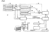
clutch control device 10 according to the embodiment includes, as shown inFig. 1 , anengine 12, primaryspeed reduction gears 14 which transmit a drive force of theengine 12, aclutch 18 which performs connection/disconnection of power transmitted to anoutput shaft 16 from theengine 12 in response to an oil pressure, atransmission 20 which selectively changes a plurality of shift positions by rotating a shift drum not shown in the drawing, and anactuator 22 which generates a liquid pressure for engaging/disengaging theclutch 18. In the explanation made hereinafter, the disconnection of power transmitted to theoutput shaft 16 from theengine 12 by the clutch is referred to as "disengagement of the clutch", and a connection of power transmitted to theoutput shaft 16 from theengine 12 by the clutch is referred to as "engagement of the clutch". - The
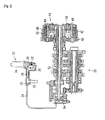
actuator 22 includes, as shown inFig. 2 , amaster cylinder 26 which is connected to ahydraulic pipe 24, amaster piston 28 which slides in the inside of themaster cylinder 26, amotor 34 which fixedly mounts aworm gear 32 on arotary shaft 30 thereof, and a sector-shapedworm wheel gear 36 to which a drive force of themotor 34 is transmitted via theworm gear 32. One end of themaster piston 28 is connected to one end of theworm wheel gear 36. For example, when themotor 34 is rotated in the normal direction, themaster piston 28 slides toward thehydraulic pipe 24 side so that an oil pressure (clutch oil pressure) in thehydraulic pipe 24 is elevated. To the contrary, when themotor 34 is rotated in the reverse direction, themaster piston 28 slides toward therotary shaft 30 side of themotor 34 so that the clutch oil pressure in thehydraulic pipe 24 is lowered. - The
clutch 18, as shown inFig. 2 , transmits the drive force by making use of a friction force generated between a plurality ofdrive friction discs 40 mounted on a clutch outer 38 and a plurality of drivenfriction discs 44 mounted on a clutch inner 42. Thedrive friction disc 40 and the drivenfriction disc 44 are alternately arranged between apressure receiving plate 46 provided to one end of the clutch inner 42 and apressure applying plate 48. - The
pressure applying plate 48 is biased by aclutch spring 50 arranged between thepressure applying plate 48 and the clutch inner 42. Thepressure applying plate 48 pushes thedrive friction discs 40 and the drivenfriction discs 44 together due to the biasing force and generates a friction force proportional to the biasing force. The stronger the biasing force, the stronger the friction force becomes so that a friction torque is increased. - Further, the
pressure applying plate 48 is rotatably joined to aslave piston 54 by way of apush rod 52. Theslave piston 54 is connected to themaster cylinder 26 of theactuator 22 by way of thehydraulic pipe 24. Accordingly, a force applied to theslave piston 54 due to the elevation of the clutch oil pressure acts so as to decrease the biasing force applied to thepressure applying plate 48 by theclutch spring 50. Accordingly, when the clutch oil pressure is 0, the biasing force applied to thepressure applying plate 48 is largest, that is, the friction torque is largest. Along with the elevation of the clutch oil pressure, the biasing force is decreased so that the friction torque is decreased. When the clutch oil pressure becomes a predetermined value or more, the biasing force becomes 0, that is, the friction torque becomes 0. - In this manner, the
clutch 18 can perform the connection/disconnection of a driving force corresponding to the clutch oil pressure generated by theactuator 22 which is controlled by theclutch control device 10. Thetransmission 20 is of a meshing clutch type which can select a gear change ratio at plural positions. The gear change ratio is shifted to arbitrary positions including a neutral position by a shift pedal not shown in the drawing which is operated by a rider. - Further, the
clutch control device 10, as shown inFig. 1 , includes ashift position sensor 60 which detects a shift position Gr of thetransmission 20, an engine rotational speed sensor 62 which detects a rotational speed (engine rotational speed Ne) of theengine 12, athrottle opening sensor 64 which detects throttle opening Th, avehicle speed sensor 66 which detects a vehicle speed, anoil pressure sensor 70 which detects a clutch oil pressure for disengaging/engaging the clutch 18, and an actuatoroperational angle sensor 72 which detects an operational position of theactuator 22, for example, a rotational angle of the worm wheel gear 36 (seeFig. 2 ). Among these parts, theshift position sensor 60, the engine rotational speed sensor 62, thethrottle opening sensor 64 and thevehicle speed sensor 66 constitute a vehiclestate detection part 74 which detects a state of the vehicle. - Further, the
clutch control device 10 according to the embodiment includes, as shown inFig. 1 , a targettorque decision part 76 which decides a target friction torque value Tt to be generated by the clutch 18 in response to a time which elapses from a point of time that the engagement of the clutch 18 starts as well as in response to a state of the vehicle, a target oilpressure decision part 78 which decides a target oil pressure value Pt corresponding to the target friction torque value Tt, anactuator control part 80 which controls theactuator 22 so as to set an oil pressure value detected by theoil pressure sensor 70 to a value equal to the target oil pressure value Pt, and a clutch engagement completion detection part 82 which detects that the clutch 18 is completely engaged. - The target
torque decision part 76 includes an enginetorque estimation part 84 which estimates a torque of theengine 12 and outputs an estimated torque as an engine torque estimated value Te, an additional torque decision part 86 which decides an additional torque value Ta in response to a state of the vehicle, and anaddition part 88 which obtains the target friction torque value Tt by adding the additional torque value Ta to the engine torque estimated value Te. - The engine
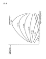
torque estimation part 84 includes anengine torque map 90 which describes the relationship among the engine rotational speed Ne, the throttle opening Th and the engine torque estimated value Te. In theengine torque map 90, as schematically shown inFig. 3 , the engine torque estimated value Te which is an estimated value of an engine torque generated by theengine 12 corresponding to a value of the engine rotational speed Ne and a value of the throttle opening Th is written. The engine torque estimated value Te is decided by preliminarily measuring a torque generated by theengine 12, for example. - Further, the engine
torque estimation part 84 decides the engine torque estimated value Te based on the detected values (engine rotational speed Ne and throttle opening Th) from the engine rotational speed sensor 62 and thethrottle opening sensor 64 and theengine torque map 90. Here, theengine 12 assumes a drive state in which theengine 12 drives theoutput shaft 16 and an engine brake state in which theoutput shaft 16 drives theengine 12. In both states, the engine torque estimated value Te is written in theengine torque map 90 as a positive value. - The additional torque decision part 86 includes an additional torque map 92 which describes first additional torque values T1 and second additional torque values T2 which are preset corresponding to shift positions, and a
timer 94 which counts a time t which elapses from a point of time that the engagement of the clutch 18 starts. - In the additional torque map, as shown in
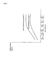
Fig. 4 schematically, a first additional torque value T1 and a second additional torque value T2 corresponding to shift positions Gr are written. When the shift position Gr is small (that is, when a gear change ratio is large), priority is assigned to the reduction of the shift shock over the engagement speed and hence, the additional torque value is small. When the shift position Gr is large (that is, when the gear change ratio is small), priority is assigned to the engagement speed over the reduction of shift shock and hence, the additional torque value is large. Further, the second additional torque value T2 is set to a value larger than the first additional torque value T1. - Then, the additional torque decision part 86 decides the first additional torque value T1 and the second additional torque value T2 based on a detected value (shift position Gr) from the
shift position sensor 60 and the additional torque map 92, and calculates the additional torque value Ta based on the first additional torque value T1, the second additional torque value T2 and a time (time t which elapses from a point of time that the engagement of the clutch 18 starts) counted by thetimer 94. After a predetermined time T elapses, the additional torque decision part 86 outputs the second additional torque value T2 as the additional torque value Ta. - That is, the additional torque decision part 86 decides the additional torque value Ta corresponding to a state of the vehicle (in this case, shift position Gr). The closer the additional torque value Ta approaches 0, the longer the engagement time becomes so that the engagement shock (shift shock) can be decreased. The larger the additional torque value Ta, the shorter the engagement time becomes so that the engagement shock is increased. Accordingly, the clutch control device can control the clutch with proper engagement time and proper engagement shock corresponding to a state of the vehicle.
- The target oil
pressure decision part 78 decides a target oil pressure value Pt corresponding to the target torque value Tt outputted from the target torque decision part 76 (the value decided by adding the additional torque value Ta to the engine torque estimated value Te). The conversion from the target torque value Tt into the target oil pressure value Pt is made using a following formula, for example.
Pt: target oil pressure value, P0: constant
k: constant, Tt: target torque value - Further, the target oil pressure value Pt may be decided using a map in which the relationship between the target torque value Tt and the target oil pressure value Pt is written.
- The clutch engagement completion detection part 82 calculates a slide speed of the clutch 18 based on the engine rotational speed Ne, the shift position Gr, and the vehicle speed, and detects the completion of the engagement when the clutch 18 does not slide.
- The
actuator control part 80 controls theactuator 22 by driving the motor 34 (seeFig. 2 ) such that an oil pressure value detected by theoil pressure sensor 70 becomes the target oil pressure value Pt. To control theactuator 22 such that the oil pressure value becomes the target oil pressure value Pt, a known technique such as a PID control, for example, may be used. - Further, in this embodiment, for example, as shown in
Fig. 6 , assuming an oil pressure value at which the clutch 18 has a maximum friction torque as a first oil pressure value Pc1 and assuming an oil pressure value at which the clutch 18 assumes a completely disengaged state as a second oil pressure value Pc2, an oil pressure value which is set closer to the first oil pressure value Pc1 is assumed as a first threshold value P1, and an oil pressure value which is set closer to the second oil pressure value Pc2 is assumed as a second threshold value P2. - In this case, when the target oil pressure value Pt exceeds the first threshold value P1 (when the target oil pressure value Pt assumes a value smaller than the first threshold value P1), the
actuator control part 80 controls theactuator 22 by driving themotor 34 such that a rotational angle of theworm wheel gear 36 which is detected by the actuatoroperational angle sensor 72 becomes equal to a first rotational angle A1 at which the clutch 18 has a maximum friction torque. Further, when the target oil pressure value Pt exceeds the second threshold value P2 (when the target oil pressure value Pt is set to a value larger than the second threshold value P2), theactuator control part 80 controls theactuator 22 by driving themotor 34 such that the rotational angle of theworm wheel gear 36 becomes equal to a second rotational angle A2 at which the clutch 18 assumes a completely disengaged state. Also in these controls, a known technique such as the PID control, for example, may be used. - In this embodiment, a torque value corresponding to a state of the vehicle is stored in the
engine torque map 90 and the additional torque map 92 respectively. Torque values which correspond to a state of the vehicle are read from theengine torque map 90 and the additional torque map 92 respectively using the enginetorque estimation part 84 and the additional torque decision part 86, and the target torque value Tt is decided based on these torque values. Then, the target torque value Tt is converted into an oil pressure value thus deciding the target oil pressure value Pt. However, in place of using the torque values of the respective torque maps, preliminarily-converted oil pressure values may be stored. In this case, the target oilpressure decision part 78 can be omitted. - Next, the manner of operation of the
clutch control device 10 according to this embodiment is explained also in conjunction with a flowchart shown inFig. 5 . - When the engagement of the clutch 18 starts, first of all, a time (elapsed time t) counted by the
timer 94 is reset to 0 in step S1 inFig. 5 . That is, thetimer 94 counts clock pulses supplied at predetermined time intervals, and the counted value indicates an elapsed time t. Hereinafter, the elapsed time t is also referred to as a counted time t. - Thereafter, in step S2, the engine
torque estimation part 84 decides the engine torque estimated value Te based on the detected values (engine rotational speed Ne and throttle opening Th) from the engine rotational speed sensor 62 and thethrottle opening sensor 64, and theengine torque map 90. - Then, in step S3, the additional torque decision part 86 compares the counted value t counted by the
timer 94 and the predetermined value T (predetermined number of pulses: predetermined time T) so as to determine whether or not the predetermined time T elapses from a point of time that the engagement of the clutch starts. - When it is determined that the predetermined time T does not elapse, the processing advances to step S4 where the additional torque decision part 86 decides the first additional torque value T1 and the second additional torque value T2 based on a detected value (shift position Gr) from the
shift position sensor 60 and the additional torque map 92 and, further, calculates the additional torque value Ta based on the first additional torque value T1, the second additional torque value T2 and a count value counted by thetimer 94. The additional torque value Ta can be obtained using a following calculation formula.
- On the other hand, in step S3, when it is determined that the predetermined time T elapses from a point of time that the engagement of the clutch starts, the processing advances to step S5 where the additional torque decision part 86 decides the second additional torque value T2 based on a detected value from the
shift position sensor 60 and the additional torque map 92 and assumes the second additional torque value T2 as the additional torque value Ta. - At a stage that the processing in step S4 or step S5 is finished, the processing advances to next step S6. In this step S6, an
addition part 88 of the targettorque decision part 76 adds the engine torque estimated value Te from the enginetorque estimation part 84 and the additional torque value Ta from the additional torque decision part 86 and decides the target torque value Tt. - Then, in step S7, the target oil
pressure decision part 78 decides the target oil pressure value Pt corresponding to the target torque value Tt from the targettorque decision part 76. - Thereafter, in step S8 and step S9, the
actuator control part 80 compares the target oil pressure value Pt with the first threshold value P1 and the second threshold value P2. When a comparison result exhibits the relationship Pt<P1, the processing advances to step S12. When the comparison result exhibits the relationship of P1 ≤ Pt<P2, the processing advances to step S10. When the comparison result exhibits the relationship of Pt≥P2, the processing advances to step S11. As described previously, the first threshold value P1 is set to a value slightly larger than the first oil pressure value Pc1 at which the clutch has the maximum friction torque. Further, the second threshold value P2 is set to a value in the vicinity of the second oil pressure value Pc2 which is a boundary between a half clutch state and a disengagement state of the clutch 18. - In step S10, the
actuator control part 80 performs a PID control of theactuator 22 such that an oil pressure value detected by theoil pressure sensor 70 becomes the target oil pressure value Pt. - In step S11, the
actuator control part 80 performs a PIC control of theactuator 22 such that a rotational angle of theworm wheel gear 36 which is detected by the actuatoroperational angle sensor 72 becomes equal to the second rotational angle A2 at which the clutch 18 assumes a completely disengaged state. - In step S12, the
actuator control part 80 performs a PID control of theactuator 22 such that a rotational angle of theworm wheel gear 36 becomes equal to the first rotational angle A1 at which the clutch 18 has the maximum friction torque. - At a stage that the processing in step S10, step S11 or step S12 is finished, the processing advances to step S13 where the clutch engagement completion detection part 82 determines whether or not the engagement of the clutch 18 is completed.
- Further, when the clutch engagement completion detection part 82 determines that the engagement of the clutch 18 is completed, the
clutch control device 10 finishes the clutch engagement control. When the clutch engagement completion detection part 82 determines that the engagement of the clutch 18 is not completed, the processing returns to step S2, and the above-mentioned clutch engagement control is continued. - Here, in this embodiment, after the predetermined time T elapses from a point of time that the engagement of the clutch is started, the additional torque value Ta is fixed to the second additional torque value T2. However, the additional torque value Ta may be estimated by extrapolation (for example, linear extrapolation using a primary function) based on the first additional torque value T1 and the second additional torque value T2, and the additional torque value Ta may be continuously increased until the completion of the engagement of the clutch is detected.
- Further, in this embodiment, exemplified is a case in which the present invention is applied to the constitution of the clutch 18 in which the friction torque of the clutch 18 is decreased corresponding to the increase of the oil pressure. However, it is needless to say that the present invention is also applicable to the constitution of the clutch 18 in which the friction torque of the clutch 18 is increased corresponding to the increase of the oil pressure. In this case, the setting of magnitude in the determination executed in step S8 and step S9 is reversed.
- Next, the manner of operation of the
clutch control device 10 according to this embodiment is explained in conjunction with timing chart shown inFig. 6 . - The clutch 18 is in a disengagement state initially. In this state, the oil pressure value is equal to or more than the second threshold value P2, and the friction torque of the clutch 18 is 0.
- Then, when the engagement of the clutch 18 starts at a point of time t1, the additional torque value Ta assumes the first additional torque value T1 at a point of time t1, and the additional torque value Ta is increased along with a lapse of time and assumes the second additional torque value T2 at a point of time t2 that a predetermined time T elapses. After the predetermined time T elapses, the additional torque value Ta is held at the second additional torque value T2. Although sliding of the clutch 18 takes place at a point of time t1, the friction torque of the clutch 18 is larger than the engine torque by an amount of the additional torque value Ta and hence, a sliding speed of the clutch 18 is gradually decreased and becomes 0 at a point of time t3. The sliding speed of the clutch 18 is decreased so that the engine rotational speed Ne is decreased whereby the engine torque estimated value Te is also decreased along with the decrease of the engine rotational speed Ne.
- When the sliding of the clutch 18 becomes 0 at a point of time t3, the completion of the engagement of the clutch 18 is detected so that the engagement control is finished.
- Usually, after the engagement of the clutch 18 is completed, the clutch 18 is controlled to have the maximum friction torque. Accordingly, the oil pressure value becomes approximately 0.
- In the
clutch control device 10 according to this embodiment, the target friction torque value Tt corresponding to a state of a vehicle is obtained and a liquid pressure is controlled corresponding to the target friction torque value Tt and hence, the clutch control device can acquire engagement feeling which conforms to the state of the vehicle. Further, by adopting such a liquid pressure control instead of a position (stroke) control of the clutch 18, a clutch control is not influenced by wear of the clutch 18 or the like and hence, a complicated control such as a control which corrects an engagement position or the like becomes unnecessary. Still further, it is unnecessary to provide a particular sensor such as a magnetic strain sensor and hence, the constitution is advantageous in reducing a manufacturing cost of the clutch control device. - Further, the clutch 18 is controlled so as to obtain the target friction torque value Tt by adding the additional torque value Ta which is properly set corresponding to a state of the vehicle to the engine torque estimated value Te and hence, the clutch control device can acquire engagement feeling which conforms to a state of the
engine 12. - Due to such constitution, a desirable additional torque value Ta can be set in response to at least any one of the shift position Gr of the
transmission 20, the engine rotational speed Ne, the throttle opening Th, the vehicle speed and the engine torque estimated value Te. For example, by setting a large additional torque value Ta when the vehicle is in a state that a high engagement speed is desired and by setting a small additional torque value Ta when the vehicle is in a state that a small engagement shock is desired, the clutch control device can acquire proper engagement performance corresponding to a state of the vehicle. - Further, the clutch 18 is controlled such that a friction torque of the clutch 18 is increased along with a lapse of time and hence, even when there is difference between an estimated engine torque and an actual engine torque, there is no possibility that the clutch 18 excessively slides.
- Further, the first additional torque value Ta is set such that the lower the shift position Gr, the smaller the first additional torque value Ta becomes and hence, priority is assigned to the reduction of the shift shock over the engagement speed whereby the shift shock becomes small. On the other hand, the first additional torque value Ta is set such that the higher the shift position Gr, the larger the first additional torque value Ta becomes and hence, priority is assigned to the engagement speed over the reduction of shift shock whereby the clutch control device can further shorten time necessary for the shift change.
- Further, in this embodiment, the
actuator 22 is controlled such that when the target oil pressure value Pt exceeds the first threshold value P1, a rotational angle of theworm wheel gear 36 which is detected by the actuatoroperational angle sensor 72 becomes equal to the first rotational angle A1 at which the clutch 18 has the maximum friction torque, and when the target oil pressure value Pt exceeds the second threshold value P2, a rotational angle of theworm wheel gear 36 becomes equal to the second rotational angle A2 at which the clutch 18 assumes the completely disengaged state. - Usually, when the friction torque of the clutch 18 assumes a value in the vicinity of the maximum friction torque or assumes a value in the vicinity of a friction torque which brings the clutch 18 into a completely disengaged state, a change of the oil pressure becomes small and hence, a control of the clutch 18 based on the oil pressure becomes difficult. However, as described above, by controlling the rotational angle of the
worm wheel gear 36, the clutch control device can favorably perform a control of the clutch 18 even in such a state. - In the above-mentioned example, the additional torque decision part 86 sets the first additional torque value T1 corresponding to the shift position Gr. Besides the above-mentioned setting, the additional torque decision part 86 may set the first additional torque value T1 such that the large first additional torque value T1 is set when the shift-up is carried out, and the small first additional torque value T1 is set when the shift-down is carried out. The detection whether the shift-up is carried out or the shift-down is carried out is made by calculating a sliding speed of the clutch 18 based on the engine rotational speed Ne, the shift position Gr or the vehicle speed, and by determining whether the sliding speed of the clutch 18 is positive or negative. When the rotational speed of the
drive friction discs 40 is higher than the rotational speed of the drivenfriction discs 44, the sliding speed is positive value so that the operation is determined as a shift-up operation. To the contrary, when the rotational speed of thedrive friction discs 40 is lower than the rotational speed of the drivenfriction discs 44, the sliding speed of the clutch is negative so that the operation is determined as a shift-down operation. - That is, the additional torque decision part 86 determines whether the operation is a shift-up operation or a shift-down operation based on a detection signal from the engine rotational speed sensor 62, the
shift position sensor 60 or thevehicle speed sensor 66. When it is determined that the operation is the shift-up operation, the additional torque decision part 86 sets the large additional torque value Ta, and when it is determined that the operation is the shift-down operation, the additional torque decision part 86 sets the small additional torque value Ta. To set the large additional torque value Ta, the large first additional torque value T1 and the large second additional torque value T2 may be set. To set the small additional torque value Ta, the small first additional torque value T1 and the small second additional torque value T2 may be set. - Usually, in a vehicle, shift shock in a shift-down operation is larger than shift shock in a shift-up operation. By adopting the above-mentioned control method, in the shift-down operation, priority is assigned to the reduction of shift shock over the engagement speed and hence, the shift shock becomes small. To the contrary, in the shift-up operation, priority is assigned to the engagement speed over the reduction of shift shock and hence, the clutch control device can further shorten time necessary for the shift change.
- In the above-mentioned embodiment, the case where the oil pressure is used in the clutch control is exemplified. Besides the oil, a liquid which has constant viscosity and can suppress the generation of rusts on equipment may be used.
-
- [
Fig. 1 ]
A block diagram showing a vehicle provided with a clutch control device according to an embodiment. - [
Fig. 2 ]
An enlarged view showing a mechanism part of an actuator and a clutch of the vehicle. - [
Fig. 3 ]
A view schematically showing an engine torque map in a form of a characteristic curve. - [
Fig. 4 ]
A view schematically showing an additional torque map in a form of a characteristic curve. - [
Fig. 5 ]
A flowchart showing the manner of operation of the clutch control device according to the embodiment. - [
Fig. 6 ]
A timing chart showing one example of the manner of operation of the clutch control device according to the embodiment. -
- 10: clutch control device
- 12: engine
- 18: clutch
- 20: transmission
- 22: actuator
- 24: hydraulic pipe
- 60: shift position sensor
- 62: engine rotational speed sensor
- 64: throttle opening sensor
- 66: vehicle speed sensor
- 70: oil pressure sensor
- 72: actuator operational angle sensor
- 74: vehicle state detection part
- 76: target torque decision part
- 78: target oil pressure decision part
- 80: actuator control part
- 82: clutch engagement completion detection part
- 84: engine torque estimation part
- 86: additional torque decision part
- 88: addition part
- 90: engine torque map
- 92: additional torque map
- 94: timer
Claims (8)
- A clutch control system comprising:a transmission capable of transmitting power generated by an engine (12) to a drive wheel;a clutch (18) mounted between said transmission and said engine, said clutch capable of performing connection and disconnection of power transmitted to said transmission from the engine;an actuator (22) capable of generating a liquid pressure necessary for engagement/disengagement of the clutch (18);a liquid pressure detection part capable of detecting the liquid pressure generated by the actuator (22);a vehicle state detection part (74) capable of detecting a state of a vehicle; anda control part capable of performing a control of the actuator (22); whereinthe clutch control system (10) further includes:a target torque decision part (76) capable of deciding a target friction torque value to be generated by the clutch (18) in response to a time which elapses from a point of time that the engagement of the clutch (18) starts as well as in response to a state of the vehicle; anda target liquid pressure decision part capable of deciding a target liquid pressure value corresponding to the target friction torque value, andthe control part capable of controlling the actuator (22) so as to set a liquid pressure value detected by the liquid pressure detection part to a value equal to the target liquid pressure value
characterized in thatthe target torque decision part (76) includes:wherein said additional torque decision part (86) decides an additional torques value bigger when the vehicle is shifted up, and smaller when the vehicle is shifted down, the additional torque decision part (86) determining whether the vehicle is shifted up when a slip speed of the clutch is of positive value, and determines whether the vehicle is shifted down when the slip speed of the clutch is of negative value.an engine torque estimation part (84) which estimates a torque of the engine (12) and sets an estimated torque as an engine torque estimated value;an additional torque decision part (86) which decides an additional torque value in response to a state of the vehicle; andan addition part (88) which obtains the target friction torque value by adding the additional torque value to the engine torque estimated value, - A clutch control system according to claim 1, wherein the state of the vehicle detected by the vehicle state detection part (74) is at least one of a shift position of the transmission (20), an engine rotational speed, throttle opening, a vehicle speed and the engine torque estimated value.
- A clutch control system according to claim 1 or 2, wherein an engine torque estimation part decides the engine torque estimated value based on a map of engine torque estimated values which are preset corresponding to at least one of an engine rotational speed, throttle opening, and an atmospheric pressure (an atmospheric pressure applied to the vehicle).
- A clutch control system according to any one of claims 1 to 3,
wherein the additional torque decision part (86) increases the additional torque value from a first additional torque value in response to the state of the vehicle at a point of time that the engagement of the clutch (18) is started toward a second additional torque value which is larger than the first additional torque value. - A clutch control system according to claim 4, wherein the additional torque decision part maintains the additional torque value at the second additional torque value after the additional torque value reaches the second additional torque value irrespective of a lapse of time.
- A clutch control system according to any one of claims 1 to 5,
wherein the additional torque decision part (86) sets the first additional torque value and the second additional torque value such that the lower a shift position of the transmission (20), the smaller the first additional torque value and the second additional torque value become. - A clutch control system according to any one of claims 1 to 6,
wherein the clutch control device (10) further includes a shift direction detection part which detects a shift change direction,
the additional torque decision part (86) sets the first additional torque value and the second additional torque value to large values when shift-up is detected by the shift direction detection part, and
the additional torque decision part (86) sets the first additional torque value and the second additional torque value to small values when shift-down is detected by the shift direction detection part. - The clutch control system according to any one of claims 1 to 7, wherein the control part is capable of controlling the actuator (22) by driving a motor (34) such that a rotational angle of a worm wheel gear (36) which is detected by the actuator operational angle sensor (72) becomes equal to a rotational angle (A1) at which the clutch (18) has a maximum friction torque.
Applications Claiming Priority (1)
| Application Number | Priority Date | Filing Date | Title |
|---|---|---|---|
| JP2008198186A JP5047088B2 (en) | 2008-07-31 | 2008-07-31 | Clutch control device |
Publications (2)
| Publication Number | Publication Date |
|---|---|
| EP2151595A1 EP2151595A1 (en) | 2010-02-10 |
| EP2151595B1 true EP2151595B1 (en) | 2012-01-25 |
Family
ID=41210558
Family Applications (1)
| Application Number | Title | Priority Date | Filing Date |
|---|---|---|---|
| EP09166609A Active EP2151595B1 (en) | 2008-07-31 | 2009-07-28 | Clutch control device |
Country Status (4)
| Country | Link |
|---|---|
| US (1) | US8202200B2 (en) |
| EP (1) | EP2151595B1 (en) |
| JP (1) | JP5047088B2 (en) |
| AT (1) | ATE543018T1 (en) |
Families Citing this family (7)
| Publication number | Priority date | Publication date | Assignee | Title |
|---|---|---|---|---|
| DE102008042783A1 (en) * | 2008-10-13 | 2010-04-15 | Robert Bosch Gmbh | Method and device for operating a drive unit |
| JP5763409B2 (en) * | 2011-05-10 | 2015-08-12 | 本田技研工業株式会社 | Vehicle engine control device |
| KR101165556B1 (en) | 2011-11-22 | 2012-07-16 | 국제종합기계 주식회사 | Wear compensation control system for multi-wet clutch |
| JP2015108438A (en) * | 2013-10-25 | 2015-06-11 | ヤマハ発動機株式会社 | Transmission device and straddle type vehicle |
| JP6712146B2 (en) * | 2016-02-15 | 2020-06-17 | Toyo Tire株式会社 | Pneumatic tire |
| JP2018052311A (en) * | 2016-09-29 | 2018-04-05 | 日立オートモティブシステムズ株式会社 | Actuator system and abnormality detection device |
| US11167762B2 (en) | 2017-06-30 | 2021-11-09 | Honda Motor Co., Ltd. | Vehicle transmission system |
Family Cites Families (12)
| Publication number | Priority date | Publication date | Assignee | Title |
|---|---|---|---|---|
| JP3334442B2 (en) * | 1995-07-12 | 2002-10-15 | スズキ株式会社 | Start control device for clutch |
| JP3430281B2 (en) * | 1996-07-03 | 2003-07-28 | 日産自動車株式会社 | Anti-creep device for automatic transmission |
| JP3589812B2 (en) * | 1996-10-01 | 2004-11-17 | ジヤトコ株式会社 | Control device for automatic transmission |
| US6299565B1 (en) | 1999-11-18 | 2001-10-09 | Ford Global Technologies, Inc. | Control strategy for an automatic transmission |
| JP2003329064A (en) | 2002-05-10 | 2003-11-19 | Yamaha Motor Co Ltd | Clutch-engagement control device |
| US6991585B2 (en) * | 2004-05-04 | 2006-01-31 | Ford Global Technologies, Llc | Torsional isolation of a convertless automatic transmission through slip control of friction clutch |
| JP4319151B2 (en) * | 2005-01-21 | 2009-08-26 | ジヤトコ株式会社 | Control device for automatic transmission |
| US7484429B2 (en) | 2005-05-10 | 2009-02-03 | Eaton Corporation | Closed loop adaptive fluid control system and method |
| DE102006014141A1 (en) | 2006-03-28 | 2007-10-04 | Zf Friedrichshafen Ag | Automatic friction clutch e.g. single-disk dry clutch, controlling method for motor vehicle, involves changing clutch torque to new reference value in pressure-controlled manner and adjusting pressure of actuator to another reference value |
| JP2007314066A (en) * | 2006-05-26 | 2007-12-06 | Nissan Motor Co Ltd | Clutch fastening controller for hybrid vehicle |
| JP2008232368A (en) * | 2007-03-23 | 2008-10-02 | Univance Corp | Driving force distributing device |
| DE102007054726B3 (en) | 2007-11-14 | 2009-07-23 | Getrag Ford Transmissions Gmbh | Method for determining a filling pressure for a clutch |
-
2008
- 2008-07-31 JP JP2008198186A patent/JP5047088B2/en active Active
-
2009
- 2009-07-02 US US12/496,701 patent/US8202200B2/en not_active Expired - Fee Related
- 2009-07-28 AT AT09166609T patent/ATE543018T1/en active
- 2009-07-28 EP EP09166609A patent/EP2151595B1/en active Active
Also Published As
| Publication number | Publication date |
|---|---|
| US8202200B2 (en) | 2012-06-19 |
| JP5047088B2 (en) | 2012-10-10 |
| EP2151595A1 (en) | 2010-02-10 |
| ATE543018T1 (en) | 2012-02-15 |
| JP2010038181A (en) | 2010-02-18 |
| US20100029441A1 (en) | 2010-02-04 |
Similar Documents
| Publication | Publication Date | Title |
|---|---|---|
| EP2273145B1 (en) | CLUTCH CONTROL DEVICE AND µ-CORRECTION FACTOR CALCULATING METHOD | |
| EP2151595B1 (en) | Clutch control device | |
| US7775338B2 (en) | Control device and control method for vehicle | |
| US6050379A (en) | Algorithm for electro-mechanical clutch actuator | |
| US7329205B2 (en) | Drive train having a twin-clutch transmission and a method for controlling the same | |
| EP2416029B1 (en) | A vehicular power transmission control apparatus | |
| JP4229176B2 (en) | Half-clutch point learning device for wet multi-plate clutch | |
| EP2655914B1 (en) | Method and system for calibrating an estimated clutch characteristic curve | |
| EP1937531B1 (en) | Shift control apparatus | |
| US20060154786A1 (en) | Method for determining a transmittable torque of a clutch in an automatic transmission of a motor vehicle | |
| US8989974B2 (en) | Method for the operation of a transmission device in a vehicle drive train, comprising at least one form-fitting shifting element and multiple frictionally engaged shifting elements | |
| EP2094989B1 (en) | Control apparatus and control method for transmission | |
| US8447482B2 (en) | Shift control device and vehicle | |
| US9695890B2 (en) | Method for determining the drainage control of a hydraulic switching element of a transmission | |
| JP3931033B2 (en) | Control device and control method for automatic transmission | |
| US7080569B2 (en) | Powershift transmission having two clutches and a device for recording the clutch torque and method for the control of a push downshift | |
| US20060148614A1 (en) | Control apparatus of automatic transmission | |
| KR20110011440A (en) | Method for controlling transmission of auto transmission vehicle using motor | |
| US11614161B2 (en) | Method for determining reference values of a sensor | |
| US11326654B2 (en) | Friction engagement element control system and method of controlling friction engagement element | |
| US10082204B2 (en) | Control apparatus and method of automatic transmission | |
| EP1188962A2 (en) | Speed change completion degree estimating system of automatic transmission and speed change control device using same | |
| JP2003004131A (en) | Control device and control method of automatic transmission |
Legal Events
| Date | Code | Title | Description |
|---|---|---|---|
| PUAI | Public reference made under article 153(3) epc to a published international application that has entered the european phase |
Free format text: ORIGINAL CODE: 0009012 |
|
| 17P | Request for examination filed |
Effective date: 20090728 |
|
| AK | Designated contracting states |
Kind code of ref document: A1 Designated state(s): AT BE BG CH CY CZ DE DK EE ES FI FR GB GR HR HU IE IS IT LI LT LU LV MC MK MT NL NO PL PT RO SE SI SK SM TR |
|
| AX | Request for extension of the european patent |
Extension state: AL BA RS |
|
| GRAP | Despatch of communication of intention to grant a patent |
Free format text: ORIGINAL CODE: EPIDOSNIGR1 |
|
| GRAS | Grant fee paid |
Free format text: ORIGINAL CODE: EPIDOSNIGR3 |
|
| GRAA | (expected) grant |
Free format text: ORIGINAL CODE: 0009210 |
|
| AK | Designated contracting states |
Kind code of ref document: B1 Designated state(s): AT BE BG CH CY CZ DE DK EE ES FI FR GB GR HR HU IE IS IT LI LT LU LV MC MK MT NL NO PL PT RO SE SI SK SM TR |
|
| REG | Reference to a national code |
Ref country code: GB Ref legal event code: FG4D |
|
| REG | Reference to a national code |
Ref country code: CH Ref legal event code: EP |
|
| REG | Reference to a national code |
Ref country code: AT Ref legal event code: REF Ref document number: 543018 Country of ref document: AT Kind code of ref document: T Effective date: 20120215 |
|
| REG | Reference to a national code |
Ref country code: IE Ref legal event code: FG4D |
|
| REG | Reference to a national code |
Ref country code: DE Ref legal event code: R096 Ref document number: 602009004871 Country of ref document: DE Effective date: 20120322 |
|
| REG | Reference to a national code |
Ref country code: NL Ref legal event code: VDEP Effective date: 20120125 |
|
| LTIE | Lt: invalidation of european patent or patent extension |
Effective date: 20120125 |
|
| PG25 | Lapsed in a contracting state [announced via postgrant information from national office to epo] |
Ref country code: HR Free format text: LAPSE BECAUSE OF FAILURE TO SUBMIT A TRANSLATION OF THE DESCRIPTION OR TO PAY THE FEE WITHIN THE PRESCRIBED TIME-LIMIT Effective date: 20120125 Ref country code: IS Free format text: LAPSE BECAUSE OF FAILURE TO SUBMIT A TRANSLATION OF THE DESCRIPTION OR TO PAY THE FEE WITHIN THE PRESCRIBED TIME-LIMIT Effective date: 20120525 Ref country code: BE Free format text: LAPSE BECAUSE OF FAILURE TO SUBMIT A TRANSLATION OF THE DESCRIPTION OR TO PAY THE FEE WITHIN THE PRESCRIBED TIME-LIMIT Effective date: 20120125 Ref country code: NL Free format text: LAPSE BECAUSE OF FAILURE TO SUBMIT A TRANSLATION OF THE DESCRIPTION OR TO PAY THE FEE WITHIN THE PRESCRIBED TIME-LIMIT Effective date: 20120125 Ref country code: BG Free format text: LAPSE BECAUSE OF FAILURE TO SUBMIT A TRANSLATION OF THE DESCRIPTION OR TO PAY THE FEE WITHIN THE PRESCRIBED TIME-LIMIT Effective date: 20120425 Ref country code: NO Free format text: LAPSE BECAUSE OF FAILURE TO SUBMIT A TRANSLATION OF THE DESCRIPTION OR TO PAY THE FEE WITHIN THE PRESCRIBED TIME-LIMIT Effective date: 20120425 Ref country code: LT Free format text: LAPSE BECAUSE OF FAILURE TO SUBMIT A TRANSLATION OF THE DESCRIPTION OR TO PAY THE FEE WITHIN THE PRESCRIBED TIME-LIMIT Effective date: 20120125 |
|
| PG25 | Lapsed in a contracting state [announced via postgrant information from national office to epo] |
Ref country code: FI Free format text: LAPSE BECAUSE OF FAILURE TO SUBMIT A TRANSLATION OF THE DESCRIPTION OR TO PAY THE FEE WITHIN THE PRESCRIBED TIME-LIMIT Effective date: 20120125 Ref country code: PL Free format text: LAPSE BECAUSE OF FAILURE TO SUBMIT A TRANSLATION OF THE DESCRIPTION OR TO PAY THE FEE WITHIN THE PRESCRIBED TIME-LIMIT Effective date: 20120125 Ref country code: LV Free format text: LAPSE BECAUSE OF FAILURE TO SUBMIT A TRANSLATION OF THE DESCRIPTION OR TO PAY THE FEE WITHIN THE PRESCRIBED TIME-LIMIT Effective date: 20120125 Ref country code: PT Free format text: LAPSE BECAUSE OF FAILURE TO SUBMIT A TRANSLATION OF THE DESCRIPTION OR TO PAY THE FEE WITHIN THE PRESCRIBED TIME-LIMIT Effective date: 20120525 Ref country code: GR Free format text: LAPSE BECAUSE OF FAILURE TO SUBMIT A TRANSLATION OF THE DESCRIPTION OR TO PAY THE FEE WITHIN THE PRESCRIBED TIME-LIMIT Effective date: 20120426 |
|
| REG | Reference to a national code |
Ref country code: AT Ref legal event code: MK05 Ref document number: 543018 Country of ref document: AT Kind code of ref document: T Effective date: 20120125 |
|
| PG25 | Lapsed in a contracting state [announced via postgrant information from national office to epo] |
Ref country code: CY Free format text: LAPSE BECAUSE OF FAILURE TO SUBMIT A TRANSLATION OF THE DESCRIPTION OR TO PAY THE FEE WITHIN THE PRESCRIBED TIME-LIMIT Effective date: 20120125 |
|
| PG25 | Lapsed in a contracting state [announced via postgrant information from national office to epo] |
Ref country code: RO Free format text: LAPSE BECAUSE OF FAILURE TO SUBMIT A TRANSLATION OF THE DESCRIPTION OR TO PAY THE FEE WITHIN THE PRESCRIBED TIME-LIMIT Effective date: 20120125 Ref country code: CZ Free format text: LAPSE BECAUSE OF FAILURE TO SUBMIT A TRANSLATION OF THE DESCRIPTION OR TO PAY THE FEE WITHIN THE PRESCRIBED TIME-LIMIT Effective date: 20120125 Ref country code: EE Free format text: LAPSE BECAUSE OF FAILURE TO SUBMIT A TRANSLATION OF THE DESCRIPTION OR TO PAY THE FEE WITHIN THE PRESCRIBED TIME-LIMIT Effective date: 20120125 Ref country code: SI Free format text: LAPSE BECAUSE OF FAILURE TO SUBMIT A TRANSLATION OF THE DESCRIPTION OR TO PAY THE FEE WITHIN THE PRESCRIBED TIME-LIMIT Effective date: 20120125 Ref country code: SE Free format text: LAPSE BECAUSE OF FAILURE TO SUBMIT A TRANSLATION OF THE DESCRIPTION OR TO PAY THE FEE WITHIN THE PRESCRIBED TIME-LIMIT Effective date: 20120125 Ref country code: DK Free format text: LAPSE BECAUSE OF FAILURE TO SUBMIT A TRANSLATION OF THE DESCRIPTION OR TO PAY THE FEE WITHIN THE PRESCRIBED TIME-LIMIT Effective date: 20120125 |
|
| PG25 | Lapsed in a contracting state [announced via postgrant information from national office to epo] |
Ref country code: SK Free format text: LAPSE BECAUSE OF FAILURE TO SUBMIT A TRANSLATION OF THE DESCRIPTION OR TO PAY THE FEE WITHIN THE PRESCRIBED TIME-LIMIT Effective date: 20120125 |
|
| PLBE | No opposition filed within time limit |
Free format text: ORIGINAL CODE: 0009261 |
|
| STAA | Information on the status of an ep patent application or granted ep patent |
Free format text: STATUS: NO OPPOSITION FILED WITHIN TIME LIMIT |
|
| 26N | No opposition filed |
Effective date: 20121026 |
|
| PG25 | Lapsed in a contracting state [announced via postgrant information from national office to epo] |
Ref country code: AT Free format text: LAPSE BECAUSE OF FAILURE TO SUBMIT A TRANSLATION OF THE DESCRIPTION OR TO PAY THE FEE WITHIN THE PRESCRIBED TIME-LIMIT Effective date: 20120125 |
|
| REG | Reference to a national code |
Ref country code: DE Ref legal event code: R097 Ref document number: 602009004871 Country of ref document: DE Effective date: 20121026 |
|
| PG25 | Lapsed in a contracting state [announced via postgrant information from national office to epo] |
Ref country code: MK Free format text: LAPSE BECAUSE OF FAILURE TO SUBMIT A TRANSLATION OF THE DESCRIPTION OR TO PAY THE FEE WITHIN THE PRESCRIBED TIME-LIMIT Effective date: 20120125 Ref country code: MC Free format text: LAPSE BECAUSE OF NON-PAYMENT OF DUE FEES Effective date: 20120731 |
|
| PG25 | Lapsed in a contracting state [announced via postgrant information from national office to epo] |
Ref country code: ES Free format text: LAPSE BECAUSE OF FAILURE TO SUBMIT A TRANSLATION OF THE DESCRIPTION OR TO PAY THE FEE WITHIN THE PRESCRIBED TIME-LIMIT Effective date: 20120506 |
|
| REG | Reference to a national code |
Ref country code: IE Ref legal event code: MM4A |
|
| PG25 | Lapsed in a contracting state [announced via postgrant information from national office to epo] |
Ref country code: IE Free format text: LAPSE BECAUSE OF NON-PAYMENT OF DUE FEES Effective date: 20120728 Ref country code: MT Free format text: LAPSE BECAUSE OF FAILURE TO SUBMIT A TRANSLATION OF THE DESCRIPTION OR TO PAY THE FEE WITHIN THE PRESCRIBED TIME-LIMIT Effective date: 20120125 |
|
| REG | Reference to a national code |
Ref country code: CH Ref legal event code: PL |
|
| GBPC | Gb: european patent ceased through non-payment of renewal fee |
Effective date: 20130728 |
|
| PG25 | Lapsed in a contracting state [announced via postgrant information from national office to epo] |
Ref country code: LI Free format text: LAPSE BECAUSE OF NON-PAYMENT OF DUE FEES Effective date: 20130731 Ref country code: TR Free format text: LAPSE BECAUSE OF FAILURE TO SUBMIT A TRANSLATION OF THE DESCRIPTION OR TO PAY THE FEE WITHIN THE PRESCRIBED TIME-LIMIT Effective date: 20120125 Ref country code: GB Free format text: LAPSE BECAUSE OF NON-PAYMENT OF DUE FEES Effective date: 20130728 Ref country code: CH Free format text: LAPSE BECAUSE OF NON-PAYMENT OF DUE FEES Effective date: 20130731 |
|
| PG25 | Lapsed in a contracting state [announced via postgrant information from national office to epo] |
Ref country code: SM Free format text: LAPSE BECAUSE OF FAILURE TO SUBMIT A TRANSLATION OF THE DESCRIPTION OR TO PAY THE FEE WITHIN THE PRESCRIBED TIME-LIMIT Effective date: 20120125 Ref country code: LU Free format text: LAPSE BECAUSE OF NON-PAYMENT OF DUE FEES Effective date: 20120728 |
|
| PG25 | Lapsed in a contracting state [announced via postgrant information from national office to epo] |
Ref country code: HU Free format text: LAPSE BECAUSE OF FAILURE TO SUBMIT A TRANSLATION OF THE DESCRIPTION OR TO PAY THE FEE WITHIN THE PRESCRIBED TIME-LIMIT Effective date: 20090728 |
|
| REG | Reference to a national code |
Ref country code: DE Ref legal event code: R084 Ref document number: 602009004871 Country of ref document: DE |
|
| REG | Reference to a national code |
Ref country code: DE Ref legal event code: R084 Ref document number: 602009004871 Country of ref document: DE Effective date: 20150505 |
|
| REG | Reference to a national code |
Ref country code: FR Ref legal event code: PLFP Year of fee payment: 8 |
|
| REG | Reference to a national code |
Ref country code: FR Ref legal event code: PLFP Year of fee payment: 9 |
|
| PGFP | Annual fee paid to national office [announced via postgrant information from national office to epo] |
Ref country code: FR Payment date: 20170613 Year of fee payment: 9 |
|
| PG25 | Lapsed in a contracting state [announced via postgrant information from national office to epo] |
Ref country code: FR Free format text: LAPSE BECAUSE OF NON-PAYMENT OF DUE FEES Effective date: 20180731 |
|
| PGFP | Annual fee paid to national office [announced via postgrant information from national office to epo] |
Ref country code: IT Payment date: 20220613 Year of fee payment: 14 |
|
| PGFP | Annual fee paid to national office [announced via postgrant information from national office to epo] |
Ref country code: DE Payment date: 20230531 Year of fee payment: 15 |
|
| PG25 | Lapsed in a contracting state [announced via postgrant information from national office to epo] |
Ref country code: IT Free format text: LAPSE BECAUSE OF NON-PAYMENT OF DUE FEES Effective date: 20230728 |