EP2151385A1 - Bag making and packaging machine - Google Patents
Bag making and packaging machine Download PDFInfo
- Publication number
- EP2151385A1 EP2151385A1 EP08740129A EP08740129A EP2151385A1 EP 2151385 A1 EP2151385 A1 EP 2151385A1 EP 08740129 A EP08740129 A EP 08740129A EP 08740129 A EP08740129 A EP 08740129A EP 2151385 A1 EP2151385 A1 EP 2151385A1
- Authority
- EP
- European Patent Office
- Prior art keywords
- receiving member
- bag
- making
- sealing mechanism
- packaging machine
- Prior art date
- Legal status (The legal status is an assumption and is not a legal conclusion. Google has not performed a legal analysis and makes no representation as to the accuracy of the status listed.)
- Withdrawn
Links
Images



Classifications
-
- B—PERFORMING OPERATIONS; TRANSPORTING
- B65—CONVEYING; PACKING; STORING; HANDLING THIN OR FILAMENTARY MATERIAL
- B65B—MACHINES, APPARATUS OR DEVICES FOR, OR METHODS OF, PACKAGING ARTICLES OR MATERIALS; UNPACKING
- B65B9/00—Enclosing successive articles, or quantities of material, e.g. liquids or semiliquids, in flat, folded, or tubular webs of flexible sheet material; Subdividing filled flexible tubes to form packages
- B65B9/10—Enclosing successive articles, or quantities of material, in preformed tubular webs, or in webs formed into tubes around filling nozzles, e.g. extruded tubular webs
- B65B9/20—Enclosing successive articles, or quantities of material, in preformed tubular webs, or in webs formed into tubes around filling nozzles, e.g. extruded tubular webs the webs being formed into tubes in situ around the filling nozzles
- B65B9/2014—Tube advancing means
- B65B9/2028—Rollers or belts
-
- B—PERFORMING OPERATIONS; TRANSPORTING
- B29—WORKING OF PLASTICS; WORKING OF SUBSTANCES IN A PLASTIC STATE IN GENERAL
- B29C—SHAPING OR JOINING OF PLASTICS; SHAPING OF MATERIAL IN A PLASTIC STATE, NOT OTHERWISE PROVIDED FOR; AFTER-TREATMENT OF THE SHAPED PRODUCTS, e.g. REPAIRING
- B29C65/00—Joining or sealing of preformed parts, e.g. welding of plastics materials; Apparatus therefor
- B29C65/02—Joining or sealing of preformed parts, e.g. welding of plastics materials; Apparatus therefor by heating, with or without pressure
- B29C65/18—Joining or sealing of preformed parts, e.g. welding of plastics materials; Apparatus therefor by heating, with or without pressure using heated tools
-
- B—PERFORMING OPERATIONS; TRANSPORTING
- B29—WORKING OF PLASTICS; WORKING OF SUBSTANCES IN A PLASTIC STATE IN GENERAL
- B29C—SHAPING OR JOINING OF PLASTICS; SHAPING OF MATERIAL IN A PLASTIC STATE, NOT OTHERWISE PROVIDED FOR; AFTER-TREATMENT OF THE SHAPED PRODUCTS, e.g. REPAIRING
- B29C66/00—General aspects of processes or apparatus for joining preformed parts
- B29C66/01—General aspects dealing with the joint area or with the area to be joined
- B29C66/05—Particular design of joint configurations
- B29C66/10—Particular design of joint configurations particular design of the joint cross-sections
- B29C66/11—Joint cross-sections comprising a single joint-segment, i.e. one of the parts to be joined comprising a single joint-segment in the joint cross-section
- B29C66/112—Single lapped joints
- B29C66/1122—Single lap to lap joints, i.e. overlap joints
-
- B—PERFORMING OPERATIONS; TRANSPORTING
- B29—WORKING OF PLASTICS; WORKING OF SUBSTANCES IN A PLASTIC STATE IN GENERAL
- B29C—SHAPING OR JOINING OF PLASTICS; SHAPING OF MATERIAL IN A PLASTIC STATE, NOT OTHERWISE PROVIDED FOR; AFTER-TREATMENT OF THE SHAPED PRODUCTS, e.g. REPAIRING
- B29C66/00—General aspects of processes or apparatus for joining preformed parts
- B29C66/40—General aspects of joining substantially flat articles, e.g. plates, sheets or web-like materials; Making flat seams in tubular or hollow articles; Joining single elements to substantially flat surfaces
- B29C66/41—Joining substantially flat articles ; Making flat seams in tubular or hollow articles
- B29C66/43—Joining a relatively small portion of the surface of said articles
- B29C66/431—Joining the articles to themselves
- B29C66/4312—Joining the articles to themselves for making flat seams in tubular or hollow articles, e.g. transversal seams
-
- B—PERFORMING OPERATIONS; TRANSPORTING
- B29—WORKING OF PLASTICS; WORKING OF SUBSTANCES IN A PLASTIC STATE IN GENERAL
- B29C—SHAPING OR JOINING OF PLASTICS; SHAPING OF MATERIAL IN A PLASTIC STATE, NOT OTHERWISE PROVIDED FOR; AFTER-TREATMENT OF THE SHAPED PRODUCTS, e.g. REPAIRING
- B29C66/00—General aspects of processes or apparatus for joining preformed parts
- B29C66/40—General aspects of joining substantially flat articles, e.g. plates, sheets or web-like materials; Making flat seams in tubular or hollow articles; Joining single elements to substantially flat surfaces
- B29C66/41—Joining substantially flat articles ; Making flat seams in tubular or hollow articles
- B29C66/43—Joining a relatively small portion of the surface of said articles
- B29C66/432—Joining a relatively small portion of the surface of said articles for making tubular articles or closed loops, e.g. by joining several sheets ; for making hollow articles or hollow preforms
- B29C66/4322—Joining a relatively small portion of the surface of said articles for making tubular articles or closed loops, e.g. by joining several sheets ; for making hollow articles or hollow preforms by joining a single sheet to itself
-
- B—PERFORMING OPERATIONS; TRANSPORTING
- B29—WORKING OF PLASTICS; WORKING OF SUBSTANCES IN A PLASTIC STATE IN GENERAL
- B29C—SHAPING OR JOINING OF PLASTICS; SHAPING OF MATERIAL IN A PLASTIC STATE, NOT OTHERWISE PROVIDED FOR; AFTER-TREATMENT OF THE SHAPED PRODUCTS, e.g. REPAIRING
- B29C66/00—General aspects of processes or apparatus for joining preformed parts
- B29C66/40—General aspects of joining substantially flat articles, e.g. plates, sheets or web-like materials; Making flat seams in tubular or hollow articles; Joining single elements to substantially flat surfaces
- B29C66/41—Joining substantially flat articles ; Making flat seams in tubular or hollow articles
- B29C66/43—Joining a relatively small portion of the surface of said articles
- B29C66/439—Joining sheets for making inflated articles without using a mould
-
- B—PERFORMING OPERATIONS; TRANSPORTING
- B29—WORKING OF PLASTICS; WORKING OF SUBSTANCES IN A PLASTIC STATE IN GENERAL
- B29C—SHAPING OR JOINING OF PLASTICS; SHAPING OF MATERIAL IN A PLASTIC STATE, NOT OTHERWISE PROVIDED FOR; AFTER-TREATMENT OF THE SHAPED PRODUCTS, e.g. REPAIRING
- B29C66/00—General aspects of processes or apparatus for joining preformed parts
- B29C66/40—General aspects of joining substantially flat articles, e.g. plates, sheets or web-like materials; Making flat seams in tubular or hollow articles; Joining single elements to substantially flat surfaces
- B29C66/49—Internally supporting the, e.g. tubular, article during joining
-
- B—PERFORMING OPERATIONS; TRANSPORTING
- B29—WORKING OF PLASTICS; WORKING OF SUBSTANCES IN A PLASTIC STATE IN GENERAL
- B29C—SHAPING OR JOINING OF PLASTICS; SHAPING OF MATERIAL IN A PLASTIC STATE, NOT OTHERWISE PROVIDED FOR; AFTER-TREATMENT OF THE SHAPED PRODUCTS, e.g. REPAIRING
- B29C66/00—General aspects of processes or apparatus for joining preformed parts
- B29C66/80—General aspects of machine operations or constructions and parts thereof
- B29C66/81—General aspects of the pressing elements, i.e. the elements applying pressure on the parts to be joined in the area to be joined, e.g. the welding jaws or clamps
- B29C66/814—General aspects of the pressing elements, i.e. the elements applying pressure on the parts to be joined in the area to be joined, e.g. the welding jaws or clamps characterised by the design of the pressing elements, e.g. of the welding jaws or clamps
- B29C66/8141—General aspects of the pressing elements, i.e. the elements applying pressure on the parts to be joined in the area to be joined, e.g. the welding jaws or clamps characterised by the design of the pressing elements, e.g. of the welding jaws or clamps characterised by the surface geometry of the part of the pressing elements, e.g. welding jaws or clamps, coming into contact with the parts to be joined
- B29C66/81411—General aspects of the pressing elements, i.e. the elements applying pressure on the parts to be joined in the area to be joined, e.g. the welding jaws or clamps characterised by the design of the pressing elements, e.g. of the welding jaws or clamps characterised by the surface geometry of the part of the pressing elements, e.g. welding jaws or clamps, coming into contact with the parts to be joined characterised by its cross-section, e.g. transversal or longitudinal, being non-flat
- B29C66/81421—General aspects of the pressing elements, i.e. the elements applying pressure on the parts to be joined in the area to be joined, e.g. the welding jaws or clamps characterised by the design of the pressing elements, e.g. of the welding jaws or clamps characterised by the surface geometry of the part of the pressing elements, e.g. welding jaws or clamps, coming into contact with the parts to be joined characterised by its cross-section, e.g. transversal or longitudinal, being non-flat being convex or concave
- B29C66/81422—General aspects of the pressing elements, i.e. the elements applying pressure on the parts to be joined in the area to be joined, e.g. the welding jaws or clamps characterised by the design of the pressing elements, e.g. of the welding jaws or clamps characterised by the surface geometry of the part of the pressing elements, e.g. welding jaws or clamps, coming into contact with the parts to be joined characterised by its cross-section, e.g. transversal or longitudinal, being non-flat being convex or concave being convex
-
- B—PERFORMING OPERATIONS; TRANSPORTING
- B29—WORKING OF PLASTICS; WORKING OF SUBSTANCES IN A PLASTIC STATE IN GENERAL
- B29C—SHAPING OR JOINING OF PLASTICS; SHAPING OF MATERIAL IN A PLASTIC STATE, NOT OTHERWISE PROVIDED FOR; AFTER-TREATMENT OF THE SHAPED PRODUCTS, e.g. REPAIRING
- B29C66/00—General aspects of processes or apparatus for joining preformed parts
- B29C66/80—General aspects of machine operations or constructions and parts thereof
- B29C66/81—General aspects of the pressing elements, i.e. the elements applying pressure on the parts to be joined in the area to be joined, e.g. the welding jaws or clamps
- B29C66/814—General aspects of the pressing elements, i.e. the elements applying pressure on the parts to be joined in the area to be joined, e.g. the welding jaws or clamps characterised by the design of the pressing elements, e.g. of the welding jaws or clamps
- B29C66/8141—General aspects of the pressing elements, i.e. the elements applying pressure on the parts to be joined in the area to be joined, e.g. the welding jaws or clamps characterised by the design of the pressing elements, e.g. of the welding jaws or clamps characterised by the surface geometry of the part of the pressing elements, e.g. welding jaws or clamps, coming into contact with the parts to be joined
- B29C66/81431—General aspects of the pressing elements, i.e. the elements applying pressure on the parts to be joined in the area to be joined, e.g. the welding jaws or clamps characterised by the design of the pressing elements, e.g. of the welding jaws or clamps characterised by the surface geometry of the part of the pressing elements, e.g. welding jaws or clamps, coming into contact with the parts to be joined comprising a single cavity, e.g. a groove
-
- B—PERFORMING OPERATIONS; TRANSPORTING
- B29—WORKING OF PLASTICS; WORKING OF SUBSTANCES IN A PLASTIC STATE IN GENERAL
- B29C—SHAPING OR JOINING OF PLASTICS; SHAPING OF MATERIAL IN A PLASTIC STATE, NOT OTHERWISE PROVIDED FOR; AFTER-TREATMENT OF THE SHAPED PRODUCTS, e.g. REPAIRING
- B29C66/00—General aspects of processes or apparatus for joining preformed parts
- B29C66/80—General aspects of machine operations or constructions and parts thereof
- B29C66/81—General aspects of the pressing elements, i.e. the elements applying pressure on the parts to be joined in the area to be joined, e.g. the welding jaws or clamps
- B29C66/814—General aspects of the pressing elements, i.e. the elements applying pressure on the parts to be joined in the area to be joined, e.g. the welding jaws or clamps characterised by the design of the pressing elements, e.g. of the welding jaws or clamps
- B29C66/8145—General aspects of the pressing elements, i.e. the elements applying pressure on the parts to be joined in the area to be joined, e.g. the welding jaws or clamps characterised by the design of the pressing elements, e.g. of the welding jaws or clamps characterised by the constructional aspects of the pressing elements, e.g. of the welding jaws or clamps
- B29C66/81453—General aspects of the pressing elements, i.e. the elements applying pressure on the parts to be joined in the area to be joined, e.g. the welding jaws or clamps characterised by the design of the pressing elements, e.g. of the welding jaws or clamps characterised by the constructional aspects of the pressing elements, e.g. of the welding jaws or clamps being made of flexible slats, flexible fins, flexible bristles or springs, e.g. coiled springs
-
- B—PERFORMING OPERATIONS; TRANSPORTING
- B29—WORKING OF PLASTICS; WORKING OF SUBSTANCES IN A PLASTIC STATE IN GENERAL
- B29C—SHAPING OR JOINING OF PLASTICS; SHAPING OF MATERIAL IN A PLASTIC STATE, NOT OTHERWISE PROVIDED FOR; AFTER-TREATMENT OF THE SHAPED PRODUCTS, e.g. REPAIRING
- B29C66/00—General aspects of processes or apparatus for joining preformed parts
- B29C66/80—General aspects of machine operations or constructions and parts thereof
- B29C66/81—General aspects of the pressing elements, i.e. the elements applying pressure on the parts to be joined in the area to be joined, e.g. the welding jaws or clamps
- B29C66/814—General aspects of the pressing elements, i.e. the elements applying pressure on the parts to be joined in the area to be joined, e.g. the welding jaws or clamps characterised by the design of the pressing elements, e.g. of the welding jaws or clamps
- B29C66/8145—General aspects of the pressing elements, i.e. the elements applying pressure on the parts to be joined in the area to be joined, e.g. the welding jaws or clamps characterised by the design of the pressing elements, e.g. of the welding jaws or clamps characterised by the constructional aspects of the pressing elements, e.g. of the welding jaws or clamps
- B29C66/81457—General aspects of the pressing elements, i.e. the elements applying pressure on the parts to be joined in the area to be joined, e.g. the welding jaws or clamps characterised by the design of the pressing elements, e.g. of the welding jaws or clamps characterised by the constructional aspects of the pressing elements, e.g. of the welding jaws or clamps comprising a block or layer of deformable material, e.g. sponge, foam, rubber
-
- B—PERFORMING OPERATIONS; TRANSPORTING
- B29—WORKING OF PLASTICS; WORKING OF SUBSTANCES IN A PLASTIC STATE IN GENERAL
- B29C—SHAPING OR JOINING OF PLASTICS; SHAPING OF MATERIAL IN A PLASTIC STATE, NOT OTHERWISE PROVIDED FOR; AFTER-TREATMENT OF THE SHAPED PRODUCTS, e.g. REPAIRING
- B29C66/00—General aspects of processes or apparatus for joining preformed parts
- B29C66/80—General aspects of machine operations or constructions and parts thereof
- B29C66/82—Pressure application arrangements, e.g. transmission or actuating mechanisms for joining tools or clamps
- B29C66/822—Transmission mechanisms
- B29C66/8221—Scissor or lever mechanisms, i.e. involving a pivot point
-
- B—PERFORMING OPERATIONS; TRANSPORTING
- B29—WORKING OF PLASTICS; WORKING OF SUBSTANCES IN A PLASTIC STATE IN GENERAL
- B29C—SHAPING OR JOINING OF PLASTICS; SHAPING OF MATERIAL IN A PLASTIC STATE, NOT OTHERWISE PROVIDED FOR; AFTER-TREATMENT OF THE SHAPED PRODUCTS, e.g. REPAIRING
- B29C66/00—General aspects of processes or apparatus for joining preformed parts
- B29C66/80—General aspects of machine operations or constructions and parts thereof
- B29C66/83—General aspects of machine operations or constructions and parts thereof characterised by the movement of the joining or pressing tools
- B29C66/834—General aspects of machine operations or constructions and parts thereof characterised by the movement of the joining or pressing tools moving with the parts to be joined
- B29C66/8341—Roller, cylinder or drum types; Band or belt types; Ball types
- B29C66/83421—Roller, cylinder or drum types; Band or belt types; Ball types band or belt types
-
- B—PERFORMING OPERATIONS; TRANSPORTING
- B29—WORKING OF PLASTICS; WORKING OF SUBSTANCES IN A PLASTIC STATE IN GENERAL
- B29C—SHAPING OR JOINING OF PLASTICS; SHAPING OF MATERIAL IN A PLASTIC STATE, NOT OTHERWISE PROVIDED FOR; AFTER-TREATMENT OF THE SHAPED PRODUCTS, e.g. REPAIRING
- B29C66/00—General aspects of processes or apparatus for joining preformed parts
- B29C66/80—General aspects of machine operations or constructions and parts thereof
- B29C66/83—General aspects of machine operations or constructions and parts thereof characterised by the movement of the joining or pressing tools
- B29C66/834—General aspects of machine operations or constructions and parts thereof characterised by the movement of the joining or pressing tools moving with the parts to be joined
- B29C66/8351—Jaws mounted on rollers, cylinders, drums, bands, belts or chains; Flying jaws
- B29C66/83541—Jaws mounted on rollers, cylinders, drums, bands, belts or chains; Flying jaws flying jaws, e.g. jaws mounted on crank mechanisms or following a hand over hand movement
- B29C66/83543—Jaws mounted on rollers, cylinders, drums, bands, belts or chains; Flying jaws flying jaws, e.g. jaws mounted on crank mechanisms or following a hand over hand movement cooperating flying jaws
-
- B—PERFORMING OPERATIONS; TRANSPORTING
- B29—WORKING OF PLASTICS; WORKING OF SUBSTANCES IN A PLASTIC STATE IN GENERAL
- B29C—SHAPING OR JOINING OF PLASTICS; SHAPING OF MATERIAL IN A PLASTIC STATE, NOT OTHERWISE PROVIDED FOR; AFTER-TREATMENT OF THE SHAPED PRODUCTS, e.g. REPAIRING
- B29C66/00—General aspects of processes or apparatus for joining preformed parts
- B29C66/80—General aspects of machine operations or constructions and parts thereof
- B29C66/84—Specific machine types or machines suitable for specific applications
- B29C66/849—Packaging machines
-
- B—PERFORMING OPERATIONS; TRANSPORTING
- B65—CONVEYING; PACKING; STORING; HANDLING THIN OR FILAMENTARY MATERIAL
- B65B—MACHINES, APPARATUS OR DEVICES FOR, OR METHODS OF, PACKAGING ARTICLES OR MATERIALS; UNPACKING
- B65B51/00—Devices for, or methods of, sealing or securing package folds or closures; Devices for gathering or twisting wrappers, or necks of bags
- B65B51/10—Applying or generating heat or pressure or combinations thereof
- B65B51/12—Applying or generating heat or pressure or combinations thereof by resilient means, e.g. brushes
-
- B—PERFORMING OPERATIONS; TRANSPORTING
- B65—CONVEYING; PACKING; STORING; HANDLING THIN OR FILAMENTARY MATERIAL
- B65B—MACHINES, APPARATUS OR DEVICES FOR, OR METHODS OF, PACKAGING ARTICLES OR MATERIALS; UNPACKING
- B65B51/00—Devices for, or methods of, sealing or securing package folds or closures; Devices for gathering or twisting wrappers, or necks of bags
- B65B51/10—Applying or generating heat or pressure or combinations thereof
- B65B51/18—Applying or generating heat or pressure or combinations thereof by endless bands or chains
-
- B—PERFORMING OPERATIONS; TRANSPORTING
- B65—CONVEYING; PACKING; STORING; HANDLING THIN OR FILAMENTARY MATERIAL
- B65B—MACHINES, APPARATUS OR DEVICES FOR, OR METHODS OF, PACKAGING ARTICLES OR MATERIALS; UNPACKING
- B65B51/00—Devices for, or methods of, sealing or securing package folds or closures; Devices for gathering or twisting wrappers, or necks of bags
- B65B51/10—Applying or generating heat or pressure or combinations thereof
- B65B51/26—Devices specially adapted for producing transverse or longitudinal seams in webs or tubes
- B65B51/30—Devices, e.g. jaws, for applying pressure and heat, e.g. for subdividing filled tubes
- B65B51/306—Counter-rotating devices
-
- B—PERFORMING OPERATIONS; TRANSPORTING
- B65—CONVEYING; PACKING; STORING; HANDLING THIN OR FILAMENTARY MATERIAL
- B65B—MACHINES, APPARATUS OR DEVICES FOR, OR METHODS OF, PACKAGING ARTICLES OR MATERIALS; UNPACKING
- B65B9/00—Enclosing successive articles, or quantities of material, e.g. liquids or semiliquids, in flat, folded, or tubular webs of flexible sheet material; Subdividing filled flexible tubes to form packages
- B65B9/10—Enclosing successive articles, or quantities of material, in preformed tubular webs, or in webs formed into tubes around filling nozzles, e.g. extruded tubular webs
- B65B9/20—Enclosing successive articles, or quantities of material, in preformed tubular webs, or in webs formed into tubes around filling nozzles, e.g. extruded tubular webs the webs being formed into tubes in situ around the filling nozzles
-
- B—PERFORMING OPERATIONS; TRANSPORTING
- B65—CONVEYING; PACKING; STORING; HANDLING THIN OR FILAMENTARY MATERIAL
- B65B—MACHINES, APPARATUS OR DEVICES FOR, OR METHODS OF, PACKAGING ARTICLES OR MATERIALS; UNPACKING
- B65B9/00—Enclosing successive articles, or quantities of material, e.g. liquids or semiliquids, in flat, folded, or tubular webs of flexible sheet material; Subdividing filled flexible tubes to form packages
- B65B9/10—Enclosing successive articles, or quantities of material, in preformed tubular webs, or in webs formed into tubes around filling nozzles, e.g. extruded tubular webs
- B65B9/20—Enclosing successive articles, or quantities of material, in preformed tubular webs, or in webs formed into tubes around filling nozzles, e.g. extruded tubular webs the webs being formed into tubes in situ around the filling nozzles
- B65B9/2014—Tube advancing means
- B65B9/2021—Tube advancing means combined with longitudinal welding devices
-
- B—PERFORMING OPERATIONS; TRANSPORTING
- B65—CONVEYING; PACKING; STORING; HANDLING THIN OR FILAMENTARY MATERIAL
- B65B—MACHINES, APPARATUS OR DEVICES FOR, OR METHODS OF, PACKAGING ARTICLES OR MATERIALS; UNPACKING
- B65B9/00—Enclosing successive articles, or quantities of material, e.g. liquids or semiliquids, in flat, folded, or tubular webs of flexible sheet material; Subdividing filled flexible tubes to form packages
- B65B9/10—Enclosing successive articles, or quantities of material, in preformed tubular webs, or in webs formed into tubes around filling nozzles, e.g. extruded tubular webs
- B65B9/20—Enclosing successive articles, or quantities of material, in preformed tubular webs, or in webs formed into tubes around filling nozzles, e.g. extruded tubular webs the webs being formed into tubes in situ around the filling nozzles
- B65B9/207—Enclosing successive articles, or quantities of material, in preformed tubular webs, or in webs formed into tubes around filling nozzles, e.g. extruded tubular webs the webs being formed into tubes in situ around the filling nozzles the web advancing continuously
-
- B—PERFORMING OPERATIONS; TRANSPORTING
- B29—WORKING OF PLASTICS; WORKING OF SUBSTANCES IN A PLASTIC STATE IN GENERAL
- B29C—SHAPING OR JOINING OF PLASTICS; SHAPING OF MATERIAL IN A PLASTIC STATE, NOT OTHERWISE PROVIDED FOR; AFTER-TREATMENT OF THE SHAPED PRODUCTS, e.g. REPAIRING
- B29C66/00—General aspects of processes or apparatus for joining preformed parts
- B29C66/80—General aspects of machine operations or constructions and parts thereof
- B29C66/81—General aspects of the pressing elements, i.e. the elements applying pressure on the parts to be joined in the area to be joined, e.g. the welding jaws or clamps
- B29C66/814—General aspects of the pressing elements, i.e. the elements applying pressure on the parts to be joined in the area to be joined, e.g. the welding jaws or clamps characterised by the design of the pressing elements, e.g. of the welding jaws or clamps
- B29C66/8141—General aspects of the pressing elements, i.e. the elements applying pressure on the parts to be joined in the area to be joined, e.g. the welding jaws or clamps characterised by the design of the pressing elements, e.g. of the welding jaws or clamps characterised by the surface geometry of the part of the pressing elements, e.g. welding jaws or clamps, coming into contact with the parts to be joined
- B29C66/81411—General aspects of the pressing elements, i.e. the elements applying pressure on the parts to be joined in the area to be joined, e.g. the welding jaws or clamps characterised by the design of the pressing elements, e.g. of the welding jaws or clamps characterised by the surface geometry of the part of the pressing elements, e.g. welding jaws or clamps, coming into contact with the parts to be joined characterised by its cross-section, e.g. transversal or longitudinal, being non-flat
- B29C66/81415—General aspects of the pressing elements, i.e. the elements applying pressure on the parts to be joined in the area to be joined, e.g. the welding jaws or clamps characterised by the design of the pressing elements, e.g. of the welding jaws or clamps characterised by the surface geometry of the part of the pressing elements, e.g. welding jaws or clamps, coming into contact with the parts to be joined characterised by its cross-section, e.g. transversal or longitudinal, being non-flat being bevelled
- B29C66/81419—General aspects of the pressing elements, i.e. the elements applying pressure on the parts to be joined in the area to be joined, e.g. the welding jaws or clamps characterised by the design of the pressing elements, e.g. of the welding jaws or clamps characterised by the surface geometry of the part of the pressing elements, e.g. welding jaws or clamps, coming into contact with the parts to be joined characterised by its cross-section, e.g. transversal or longitudinal, being non-flat being bevelled and flat
Definitions
- the present invention relates to a bag-making and packaging machine and particularly relates to sealing a packaging material.
- Such technologies are, for example, disclosed in document 1 ( U.S. Patent No. 4,950,345 ) and document 2 ( JP-A No. 2006-1552 ).
- document 1 U.S. Patent No. 4,950,345
- document 2 JP-A No. 2006-1552
- the overlapping portion of the packaging material is sandwiched between and sealed by a heat sealing die and a back-up pad.
- document 2 the overlapping portion of the packaging material is sandwiched between and sealed by a rotating belt and a receiving member.
- the back-up pad is disposed across the entirety of a position facing the heat sealing die.
- force acting on the packaging material when sealing the packaging material ends up dispersing. When force disperses, force necessary for sealing becomes insufficient and it becomes easier for poor sealing to arise.
- the receiving member in order to prevent dispersal of force acting on the packaging material, the receiving member is plurally divided and disposed.
- the present invention has been made in light of the aforementioned circumstances, and it is an object thereof to reduce poor sealing of an overlapping portion of a packaging material that has been rolled into a cylindrical shape.
- a bag-making and packaging machine pertaining to the present invention comprises a forming mechanism, a vertical sealing mechanism, a transverse sealing mechanism and a receiving member and packages contents while making bags from a sheet-like packaging material.
- the forming mechanism rolls the sheet-like packaging material into a cylindrical shape to form a cylindrical packaging material.
- the vertical sealing mechanism seals an overlapping portion of the cylindrical packaging material with heat vertically along a direction in which the cylindrical packaging material extends.
- the transverse sealing mechanism traverses the cylindrical packaging material and seals the cylindrical packaging material with heat.
- the receiving member is attached to the forming mechanism in a position facing the vertical sealing mechanism and sandwiches the overlapping portion together with the vertical sealing mechanism.
- the receiving member has elasticity and presses, with the elasticity, the overlapping portion toward the vertical sealing mechanism.
- the receiving member has elasticity and presses, with this elasticity, the overlapping portion toward the vertical sealing mechanism, so force necessary for sealing can be applied to the overlapping portion, and therefore poor sealing can be reduced.
- the receiving member is made of metal; for example, spring steel can be employed.
- the strength of the receiving member can be raised, and therefore the elasticity of the receiving member can be maintained.
- the receiving member has a shape that curves toward the vertical sealing mechanism.
- the receiving member is detachably attached to the forming mechanism.
- the receiving member can be removed when cleaning the forming mechanism, and therefore damage to the receiving member caused by such cleaning can be prevented.
- a buffer material is disposed on a surface of the receiving member on the vertical sealing mechanism side.
- the buffer material contacts the overlapping portion of the packaging material.
- shock to the packaging material resulting from pressing the packaging material toward the vertical sealing mechanism can be absorbed by the buffer material.
- the packaging material that has been sandwiched between the vertical sealing mechanism and the receiving mechanism can be prevented from being damaged.
- the buffer material that has elasticity the packaging material can be prevented from being damaged.
- the buffer material that has heat resistance the buffer material can be prevented from being damaged by the heat of the vertical sealing mechanism.
- a material where friction of its surface on the vertical sealing mechanism side is small may also be employed for the buffer material. This buffer material virtually does not hinder the conveyance of the packaging material.
- the bag-making and packaging machine may further comprise a first support portion that supports the receiving member on a downstream side in a conveyance direction of the packaging material and deters the receiving member from shifting in the conveyance direction.
- a first support portion that supports the receiving member on a downstream side in a conveyance direction of the packaging material and deters the receiving member from shifting in the conveyance direction.
- the vertical sealing mechanism includes an annular belt that rotates on the basis of a conveyance speed of the packaging material, and even when force toward the downstream side arises in the receiving member because of this belt, the receiving member does not shift toward the downstream side.
- the bag-making and packaging machine equipped with the first support portion to further comprise a second support portion.
- the second support portion supports the receiving member on the downstream side and deters the receiving member from shifting from a position of the overlapping portion.
- the bag-making and packaging machine equipped with the first support portion to further comprise a third support portion.
- the third support portion supports the receiving member on an upstream side in the conveyance direction.
- the receiving member can be fixed to the forming mechanism.
- the receiving member has elasticity and presses, with this elasticity, the overlapping portion toward the vertical sealing mechanism, so force necessary for sealing can be applied to the overlapping portion, and therefore poor sealing can be reduced.
- FIG. 1 is a diagram conceptually showing a bag-making and packaging machine 1 pertaining to an embodiment of the present invention.
- the bag-making and packaging machine 1 is equipped with a film roll holding section 22 and a bag making section 10. These components will be described later, but first an overview of the bag-making and packaging machine 1 will be described.
- the bag-making and packaging machine 1 packs a predetermined amount of contents C such as confectionery into bags using a packaging material.
- contents C such as confectionery
- bags B into which the contents C have been packed are formed by sealing, in a vertical direction and a transverse direction, a packaging material that has been rolled into a cylindrical shape.
- thermoplastic film F for example, can be employed for the packaging material.
- the amount of the contents C is measured by a meter 2 disposed separately from the bag-making and packaging machine 1, and a predetermined amount of the contents C is delivered to the bag-making and packaging machine 1.
- the meter 2 may also, for example, be disposed in the bag-making and packaging machine.
- the film roll holding section 22 includes a film roll and a sensor. Sheet-like film F is wrapped around the film roll, and the film roll reels out the film F.
- the film F that has been reeled out from the film roll travels over the top side of the bag-making and packaging machine 1 via dancer rollers and the like and is conveyed to the bag making section 10.
- the dancer rollers prevent the film F from becoming slack and meandering during conveyance by maintaining the tension in the film F in a predetermined range.
- the sensor is installed in the vicinity of the film roll and detects the remaining amount of the film F wrapped around the film roll. Additionally, when the remaining amount becomes equal to or less than a predetermined amount, notification that the remaining amount is small is given by a buzzer or the lighting of a lamp.
- FIG. 2 is a perspective diagram conceptually showing the bag making section 10.
- the bag making section 10 is equipped with a forming mechanism 13, a conveyance mechanism 14, a vertical sealing mechanism 16, a transverse sealing mechanism 17, a receiving member 31 and a buffer material 4.
- these respective components will be specifically described. It will be noted that the receiving member 31 and the buffer material 4 are shown in later-described FIG. 5 .
- the forming mechanism 13 includes a tube 13b and a former 13a and rolls, into a cylindrical shape, the film F that has been conveyed from the film roll holding section 22.
- the tube 13b is a cylindrical member, and the top end and the bottom end of the tube 13b are both open. A predetermined amount of the contents C that has been measured by the meter 2 is put into the tube 13b from the top end of the tube 13b. The contents C that have been put into the tube 13b travel through the inside of the tube 13b and are discharged from the bottom end of the tube 13b and into the bags B before the bags B are closed.
- the former 13a is disposed on the top end side of the tube 13b so as to surround the tube 13b.
- the portion of the former 13a on the back side with respect to the tube 13b has a shape where the collar of a sailor uniform is spread toward the back side.
- the portion of the former 13a that surrounds the tube 13b from its right side and the portion of the former 13a that surrounds the tube 13b from its left side overlap each other.
- the film F that has been conveyed from the back side with respect to the tube 13b slides on the surface of the top side of the former 13a and is fed between the former 13a and the tube 13b.
- the film F is rolled into a cylindrical shape such that the ends of the film F overlap each other on the front side of the tube 13b (overlapping portion F2).
- tube 13b and the former 13a can be replaced depending on the size of the bags B that are to be formed.
- the conveyance mechanism 14 includes a drive roller 14a, a driven roller 14b and a belt 14c and downwardly conveys the cylindrical film F that surrounds the tube 13b ( FIG. 2 ).
- the drive roller 14a is disposed on the top side and the driven roller 14b is disposed on the bottom side.
- the belt 14c is stretched around the drive roller 14a and the driven roller 14b.
- the film F is sandwiched between the belt 14c and the tube 13b. Additionally, when the drive roller 14a rotates, the belt 14c also rotates. Thus, the film F contacting the belt 14c is conveyed downward. It will be noted that the drive roller 14a can be caused to rotate by a motor or the like, for example.
- FIG. 3 is a diagram showing the bag making section 10 as seen from its front side.
- the conveyance mechanism 14 is disposed on both the left side and the right side with respect to the tube 13b. According to this aspect, it is easy to downwardly convey the cylindrical film F.
- FIG. 4 is perspective diagram conceptually showing the vertical sealing mechanism 16.
- FIG. 5 is a diagram showing a cross section at position V-V shown in FIG. 4 .
- the vertical sealing mechanism 16 seals the overlapping portion F2 of the rolled film F in its vertical direction with heat.
- vertical direction refers to the direction in which the film F is conveyed.
- the vertical sealing mechanism 16 includes a heater belt 16a, a heat emitting component 16b and pulleys 16c.
- the pulleys 16c are disposed one each on the top side and the bottom side.
- the heater belt 16a is stretched around these pulleys 16c so as to have a predetermined tension.
- a belt made of metal can be employed for the heater belt 16a and that the thickness thereof is 0.15 mm, for example.
- the heater belt 16a when the pulleys 16c rotate, the heater belt 16a also rotates. At this time, the heater belt 16a rotates at substantially the same speed as the conveyance speed of the film F. It will be noted that the pulleys 16c can be caused to rotate by a motor or the like, for example.
- the heat emitting body 16b heats the heater belt 16a. Specifically, in FIG. 4 , the heat emitting body 16 is disposed on the inner peripheral side of the heater belt 16a. Additionally, the heat emitting body 16b applies heat to the rotating portion of the heater belt 16a on the tube 13b side and heats this portion to 140 to 150°C.
- the overlapping portion F2 ( FIG. 5 ) that has been sandwiched between the heater belt 16a and the later-described receiving member 31 is sealed in its vertical direction with heat by the vertical sealing mechanism 16 (seal portion F1).
- the vertical sealing mechanism 16 is, for example, controlled by a controller 20 as shown in FIG. 2 .
- the temperature of the heat emitting body 16b and the rotational speed of the heater belt 16a are controlled by the controller 20.
- FIG. 6 is a diagram conceptually showing the transverse sealing mechanism 17.
- the transverse sealing mechanism 17 is disposed further on the bottom side than the bottom end of the tube 13b, seals the rolled film F in its transverse direction, and closes the tops and bottoms of the bags B.
- the transverse sealing mechanism 17 includes a pair of transverse seal units 17a.
- Each of the pair of transverse seal units 17a includes a seal jaw 51, a coupling portion 17b and a shaft 17c.
- the coupling portion 17b couples together the seal jaw 51 and the shaft 17c.
- the shaft 17c is capable of self-rotation and is also capable of moving forward and backward. For example, by using a motor for a gyration, the shaft 17c can be caused to self rotate. Further, by using a motor for moving the shaft, the shaft 17c can be caused to move forward and backward.
- the seal jaws 51 belonging to the pair of transverse seal units 17 are arranged in front and in back.
- the pair of seal jaws 51 sandwich the film F, which has been sealed in its vertical direction by the vertical sealing mechanism 16, from its front side and its back side and seal the film F in its transverse direction (position r2).
- the seal jaws 51 traverse the cylindrical film F and seal the film F in its transverse direction.
- transverse direction is the direction facing the left side or the right side.
- Sealing of the film F by the pair of seal jaws 51 is performed by applying heat and pressure to the film F.
- the pressure applied to the film F can be adjusted by the shaft moving-use motor that causes the shafts 17c to move forward and backward.
- the seal jaws 51 After the pair of seal jaws 51 sandwich the film F from its front side and its back side, the seal jaws 51 move downward to a predetermined position r1 while sealing the film F (trajectories T1). Thus, the seal jaws 51 can move the film F that has been sealed in its transverse direction downward. Thereafter, the seal jaws 51 release the film F.
- the pair of seal jaws 51 move toward mutually opposite sides from the predetermined position r1 to the predetermined position r2 while drawing an arc (trajectories T2). It will be noted that the predetermined position r2 is located further downward than the bottom end of the tube 13b.
- the pair of seal jaws 51 that have moved to the predetermined position r1 again sandwich the film F from its front side and its back side and seal the film F along its transverse direction.
- movement of the seal jaws 51 along the trajectories T1 is executed as a result of the shafts 17c belonging to the pair of transverse seal units 17a moving toward mutually opposite sides while self-rotating. Movement of the seal jaws 51 along the trajectories T2 is executed by only self-rotation of the shafts 17c.
- a cutter is built into one of the pair of seal jaws 51. This cutter cuts the vertical direction center vicinity of the portion that has been sealed in its transverse direction. Thus, the top sides of the bag into which the contents C have been packed can be closed, and the downstream sides of the bag into which the contents C will next be packed can be closed. Thus, it is not necessary to close the downstream sides of the bags again before putting the contents C into the bags.
- the receiving member 31 will be described using FIG. 5 .
- the receiving member 31 is attached to the tube 13b and faces the vertical sealing mechanism 16.
- the overlapping portion F2 of the film F is sandwiched between the vertical sealing mechanism 16 and the receiving member 31 ( FIG. 5 ).
- the overlapping portion F2 is sealed in its vertical direction with heat by the vertical sealing mechanism 16 (seal portion F1).
- the receiving member 31 faces the portion of the heater belt 16a belonging to the vertical sealing mechanism 16 on the tube 13b side. Additionally, the overlapping portion F2 is sandwiched between the heater belt 16a and the receiving member 31 ( FIG. 5 )
- the buffer material 4 is disposed on the surface of the receiving member 31 on the vertical sealing mechanism 16 side.
- the buffer material 4 contacts the overlapping portion F2 between the vertical sealing mechanism 16 and the receiving member 31. It will be noted that the thickness of the buffer material 4 is 3 to 6 mm.
- the buffer material 4 By disposing the buffer material 4 between the receiving member 31 and the film F, the film F that has been sandwiched between the vertical sealing mechanism 16 and the receiving member 31 can be prevented from being damaged.
- a material that has elasticity or a material that has heat resistance can be employed for the buffer material 4. According to the buffer material 4 that has elasticity, the film F can be prevented from being damaged. According to the buffer material 4 that has heat resistance, the buffer material 4 can be prevented from being damaged by the heat of the vertical sealing mechanism 16.
- a material where friction of its surface on the vertical sealing mechanism 16 side is small may also be employed for the buffer material 4.
- This buffer material 4 virtually does not hinder the conveyance of the film F. In other words, even when the film F is sandwiched between the vertical sealing mechanism 16 and the receiving member 31, friction that arises between the buffer material 4 and the film F is small, and therefore the film F can be easily conveyed downward.
- Teflon (registered trademark) rubber, silicon rubber, silicon sponge, leather, wood or ultra high molecular weight polyethylene can be employed for the material of the buffer material 4.
- the buffer material 4 is not limited to these materials, and various materials can be employed as long as they have elasticity or heat resistance or as long as their friction is small.
- the bag-making and packaging machine 1 pertaining to the embodiment of the present invention has characteristics particularly in the receiving member 31. Below, the shape of the receiving member 31 and the attachment of the receiving member 31 to the tube 13b will be described.
- FIG. 7 is a diagram showing the bag making section 10 as seen from its right side and conceptually showing the shape of the receiving member 31.
- FIG. 8 is an enlarged diagram showing region VIII shown in FIG. 7 in order to clarify the shape of the receiving member 31.
- the receiving member 31 has elasticity and presses, with this elasticity, the overlapping portion F2 of the film F ( FIG. 5 ) toward the vertical sealing mechanism 16.
- the receiving member 31 curves toward the vertical sealing mechanism 16 and extends up and down. Additionally, the top end and the bottom end of the receiving member 31 are attached to the tube 13b. It will be noted that the thickness of the receiving member 31 is about 0.6 mm.
- the receiving member 31 gives rise to a repulsive force with respect to the pressure from the vertical sealing mechanism 16 side. In other words, elasticity arises in the receiving member 31.
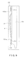
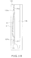
- the receiving member 31 may also curve toward the vertical sealing mechanism 16 as shown in FIG. 9 and FIG. 10 , for example. That is, in FIG. 8 , the center vicinity of the receiving member 31 in the vertical direction comes closest to the vertical sealing mechanism 16, but in FIG. 9 , the upper side of the receiving member 31 comes closest to the vertical sealing mechanism 16, and in FIG. 10 , the lower side of the receiving member 31 comes closest to the vertical sealing mechanism 16.
- the overlapping portion F2 is pressed toward the vertical sealing mechanism 16 by the elasticity of the receiving member 31, so force necessary for sealing can be applied to the overlapping portion F2.
- poor sealing of the overlapping portion F2 can be reduced.
- a member made of metal for the receiving member 31 for example, spring steel can be employed.
- the strength of the receiving member 31 can be raised, and therefore the elasticity of the receiving member 31 can be maintained.
- a stainless spring material JIS standard/SUS 304 CSP
- rusting of the receiving member 31 can also be prevented.
- the buffer material 4 is attached to the receiving member 31, and shock to the film F resulting from pressing the film F toward the vertical sealing mechanism 16 is absorbed by the buffer material 4.
- the receiving member 31 itself has elasticity, shock to the film F can be absorbed even without the buffer material 4.
- the receiving member 31 is a member that also has heat resistance or a member where friction of its surface on the side of the vertical sealing mechanism 16 is small, the receiving member 31 can take on the function of the buffer material 4.
- a receiving member 31 that takes on the function of the buffer material 4 can be obtained by using Teflon (registered trademark) or silicon as the material.
- Teflon registered trademark
- silicon silicon
- a material that does not go against the Food Sanitation Act must be used for the material of the receiving member 31.
- the receiving member 31 is detachably attached to the tube 13b.
- support members 131 and 132 are disposed one each on the top and the bottom on the surface on the front side of the tube 13b.
- the support members 131 and 132 detachably support the top end and the bottom end of the receiving member 31.
- the support member 131 supports the receiving member 31 on the downstream side in the conveyance direction of the film F and deters the receiving member 31 from shifting in the conveyance direction. This will be described specifically below.
- FIG. 11 is a diagram showing the bag making section 10 as seen from its bottom side.
- the support member 131 has a concave shape and, utilizing the portion that is concavely recessed, forms a hole 131a for supporting the receiving member 31 together with the tube 13b.
- the hole 131a is surrounded by the support member 131 and the tube 13b.
- the support member 132 also has the same shape as that of the support member 131 and forms a hole 132a for supporting the receiving member 31 together with the tube 13b.
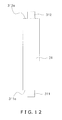
- FIG. 12 is a diagram showing the receiving member 31 shown in FIG. 8 to FIG. 10 as seen from its front side.
- the bottom end of the receiving member 31 has a downwardly convex shape.
- a portion 311 that projects convexly from the bottom end is inserted into the hole 131a ( FIG. 8 to FIG. 10 ).
- a portion 311 a on the shoulder of the convexity on the bottom end catches on the support member 131, whereby the receiving member 31 is prevented from shifting downward ( FIG. 11 ).
- the receiving member 31 does not shift downstream (in the conveyance direction).
- the receiving member 31 does not shift to the downstream side (in the conveyance direction) because the aforementioned receiving member 31 is supported by the first support member 131.
- the portion 311 that has been inserted into the hole 131a is surrounded by the support member 131 and the tube 13b ( FIG. 11 ), so it does not shift from the position of the overlapping portion F2.
- the support member 131 supports the receiving member 131 on the downstream side and deters the receiving member 31 from shifting from the position of the overlapping portion F2.
- the top end of the receiving member 31 has an upwardly convex shape ( FIG. 12 ).
- a portion 312 that projects convexly from the top end is inserted into the hole 132a ( FIG. 8 to FIG. 10 ). Additionally, a portion 312a on the shoulder of the convexity on the top end catches on the support member 132.
- the top end of the receiving member 31 is also supported by the support member 132, so the receiving member 31 can be fixed to the tube 13b.
- the portion 312 that has been inserted into the hole 132a is surrounded by the support member 132 and the tube 13b ( FIG. 11 ), so it does not shift from the position of the overlapping portion F2.
- the support member 132 supports the receiving member 31 on the downstream side and deters the receiving member 31 from shifting from the position of the overlapping portion F2.
- the aforementioned receiving member 31 is attachable to and detachable from the forming mechanism 13, the receiving member 31 can be removed when cleaning the forming mechanism 13 and particularly the tube 13b. Thus, damage to the receiving member 31 caused by such cleaning can be prevented.
- the phenomenon of peeling of the buffer material 4 from the receiving member 31 can also be prevented.
- each of the support members 131 and 132 takes on both the function (function A) of preventing shifting of the receiving member 31 to the downstream side (in the conveyance direction) and the function (function B) of preventing shifting of the receiving member 31 from the position of the overlapping portion F2, but, for example, support members that are separate in terms of function A and function B may also be disposed on the tube 13b.
Landscapes
- Engineering & Computer Science (AREA)
- Mechanical Engineering (AREA)
- Containers And Plastic Fillers For Packaging (AREA)
Abstract
Description
- The present invention relates to a bag-making and packaging machine and particularly relates to sealing a packaging material.
- Conventionally, technologies that pack a predetermined amount of contents such as confectionery into bags have been proposed. Specifically, an overlapping portion of a packaging material that has been rolled into a cylindrical shape is vertically sealed. Then, a predetermined amount of the contents is put into the packaging material, and thereafter the packaging material is transversely sealed and closed. The closed portion is cut by a cutter or the like.
- Such technologies are, for example, disclosed in document 1 (
U.S. Patent No. 4,950,345 ) and document 2 (JP-A No. 2006-1552 document 1, the overlapping portion of the packaging material is sandwiched between and sealed by a heat sealing die and a back-up pad. Indocument 2, the overlapping portion of the packaging material is sandwiched between and sealed by a rotating belt and a receiving member. - Incidentally, in
document 1, the back-up pad is disposed across the entirety of a position facing the heat sealing die. However, in this aspect, force acting on the packaging material when sealing the packaging material ends up dispersing. When force disperses, force necessary for sealing becomes insufficient and it becomes easier for poor sealing to arise. - Thus, in
document 2, in order to prevent dispersal of force acting on the packaging material, the receiving member is plurally divided and disposed. - However, even in the technology of
document 2, there is the fear that force acting on the packaging material will end up dispersing to each of the plural receiving members and that force necessary for sealing will become insufficient. - The present invention has been made in light of the aforementioned circumstances, and it is an object thereof to reduce poor sealing of an overlapping portion of a packaging material that has been rolled into a cylindrical shape.
- A bag-making and packaging machine pertaining to the present invention comprises a forming mechanism, a vertical sealing mechanism, a transverse sealing mechanism and a receiving member and packages contents while making bags from a sheet-like packaging material. The forming mechanism rolls the sheet-like packaging material into a cylindrical shape to form a cylindrical packaging material. The vertical sealing mechanism seals an overlapping portion of the cylindrical packaging material with heat vertically along a direction in which the cylindrical packaging material extends. The transverse sealing mechanism traverses the cylindrical packaging material and seals the cylindrical packaging material with heat. The receiving member is attached to the forming mechanism in a position facing the vertical sealing mechanism and sandwiches the overlapping portion together with the vertical sealing mechanism. The receiving member has elasticity and presses, with the elasticity, the overlapping portion toward the vertical sealing mechanism.
- According to this bag-making and packaging machine, the receiving member has elasticity and presses, with this elasticity, the overlapping portion toward the vertical sealing mechanism, so force necessary for sealing can be applied to the overlapping portion, and therefore poor sealing can be reduced.
- Preferably, the receiving member is made of metal; for example, spring steel can be employed. Thus, the strength of the receiving member can be raised, and therefore the elasticity of the receiving member can be maintained.
- From the standpoint of imparting elasticity to the receiving member, preferably the receiving member has a shape that curves toward the vertical sealing mechanism.
- More preferably, the receiving member is detachably attached to the forming mechanism. Thus, the receiving member can be removed when cleaning the forming mechanism, and therefore damage to the receiving member caused by such cleaning can be prevented.
- From the standpoint of preventing damage to the receiving member, preferably a buffer material is disposed on a surface of the receiving member on the vertical sealing mechanism side. The buffer material contacts the overlapping portion of the packaging material. Thus, shock to the packaging material resulting from pressing the packaging material toward the vertical sealing mechanism can be absorbed by the buffer material. Thus, the packaging material that has been sandwiched between the vertical sealing mechanism and the receiving mechanism can be prevented from being damaged.
- It is preferable to employ a material that has elasticity or a material that has heat resistance for the buffer material. According to the buffer material that has elasticity, the packaging material can be prevented from being damaged. According to the buffer material that has heat resistance, the buffer material can be prevented from being damaged by the heat of the vertical sealing mechanism.
- A material where friction of its surface on the vertical sealing mechanism side is small may also be employed for the buffer material. This buffer material virtually does not hinder the conveyance of the packaging material.
- Further, it is preferable for the bag-making and packaging machine to further comprise a first support portion that supports the receiving member on a downstream side in a conveyance direction of the packaging material and deters the receiving member from shifting in the conveyance direction. According to this bag-making and packaging machine, even when force toward the downstream side arises in the receiving member because of friction arising between the packaging material and the receiving member during conveyance of the packaging material, the receiving member does not shift toward the downstream side. The vertical sealing mechanism includes an annular belt that rotates on the basis of a conveyance speed of the packaging material, and even when force toward the downstream side arises in the receiving member because of this belt, the receiving member does not shift toward the downstream side.
- Further, it is preferable for the bag-making and packaging machine equipped with the first support portion to further comprise a second support portion. The second support portion supports the receiving member on the downstream side and deters the receiving member from shifting from a position of the overlapping portion.
- Further, it is preferable for the bag-making and packaging machine equipped with the first support portion to further comprise a third support portion. The third support portion supports the receiving member on an upstream side in the conveyance direction. Thus, the receiving member can be fixed to the forming mechanism.
- According to the bag-making and packaging machine pertaining to the present invention, the receiving member has elasticity and presses, with this elasticity, the overlapping portion toward the vertical sealing mechanism, so force necessary for sealing can be applied to the overlapping portion, and therefore poor sealing can be reduced.
-
-
FIG. 1 is a diagram conceptually showing a bag-making and packaging machine pertaining to an embodiment of the present invention. -
FIG. 2 is a perspective diagram conceptually showing a bag making section. -
FIG. 3 is diagram showing the bag making section as seen from its front side. -
FIG. 4 is a perspective diagram conceptually showing a vertical sealing mechanism. -
FIG. 5 is a diagram showing a cross section at position V-V shown inFIG. 4 . -
FIG. 6 is a diagram conceptually showing a transverse sealing mechanism. -
FIG. 7 is a diagram showing the bag making section as seen from its right side. -
FIG. 8 is an enlarged diagram showing region VIII shown inFIG. 7 . -
FIG. 9 is a diagram conceptually showing the shape of a receiving member. -
FIG. 10 is a diagram conceptually showing the shape of the receiving member. -
FIG. 11 is a diagram showing the bag making section as seen from its bottom side. -
FIG. 12 is a diagram showing the receiving member as seen from its front side. -
- 1
- Bag-Making and Packaging Machine
- 4
- Buffer Material
- 13
- Forming Mechanism
- 16
- Vertical Sealing Mechanism
- 16a
- Heater Belt (Belt)
- 17
- Transverse Sealing Mechanism
- 31
- Receiving Member
- 131
- Support Member (First Support Portion, Second Support Portion)
- 132
- Support Member (Third Support Portion)
- B
- Bag
- F
- Film (Packaging Material)
- F2
- Overlapping Portion
-
FIG. 1 is a diagram conceptually showing a bag-making andpackaging machine 1 pertaining to an embodiment of the present invention. The bag-making andpackaging machine 1 is equipped with a filmroll holding section 22 and abag making section 10. These components will be described later, but first an overview of the bag-making andpackaging machine 1 will be described. - The bag-making and
packaging machine 1 packs a predetermined amount of contents C such as confectionery into bags using a packaging material. Specifically, bags B into which the contents C have been packed are formed by sealing, in a vertical direction and a transverse direction, a packaging material that has been rolled into a cylindrical shape. - It will be noted that a thermoplastic film F, for example, can be employed for the packaging material. Further, the amount of the contents C is measured by a
meter 2 disposed separately from the bag-making andpackaging machine 1, and a predetermined amount of the contents C is delivered to the bag-making andpackaging machine 1. Themeter 2 may also, for example, be disposed in the bag-making and packaging machine. - The film
roll holding section 22 includes a film roll and a sensor. Sheet-like film F is wrapped around the film roll, and the film roll reels out the film F. - The film F that has been reeled out from the film roll travels over the top side of the bag-making and
packaging machine 1 via dancer rollers and the like and is conveyed to thebag making section 10. The dancer rollers prevent the film F from becoming slack and meandering during conveyance by maintaining the tension in the film F in a predetermined range. - The sensor is installed in the vicinity of the film roll and detects the remaining amount of the film F wrapped around the film roll. Additionally, when the remaining amount becomes equal to or less than a predetermined amount, notification that the remaining amount is small is given by a buzzer or the lighting of a lamp.
-
FIG. 2 is a perspective diagram conceptually showing thebag making section 10. Thebag making section 10 is equipped with a formingmechanism 13, aconveyance mechanism 14, avertical sealing mechanism 16, atransverse sealing mechanism 17, a receivingmember 31 and abuffer material 4. Below, these respective components will be specifically described. It will be noted that the receivingmember 31 and thebuffer material 4 are shown in later-describedFIG. 5 . - The forming
mechanism 13 includes atube 13b and a former 13a and rolls, into a cylindrical shape, the film F that has been conveyed from the filmroll holding section 22. - The
tube 13b is a cylindrical member, and the top end and the bottom end of thetube 13b are both open. A predetermined amount of the contents C that has been measured by themeter 2 is put into thetube 13b from the top end of thetube 13b. The contents C that have been put into thetube 13b travel through the inside of thetube 13b and are discharged from the bottom end of thetube 13b and into the bags B before the bags B are closed. - The former 13a is disposed on the top end side of the
tube 13b so as to surround thetube 13b. - Specifically, the portion of the former 13a on the back side with respect to the
tube 13b has a shape where the collar of a sailor uniform is spread toward the back side. On the front side with respect to thetube 13b, the portion of the former 13a that surrounds thetube 13b from its right side and the portion of the former 13a that surrounds thetube 13b from its left side overlap each other. - The film F that has been conveyed from the back side with respect to the
tube 13b slides on the surface of the top side of the former 13a and is fed between the former 13a and thetube 13b. Thus, the film F is rolled into a cylindrical shape such that the ends of the film F overlap each other on the front side of thetube 13b (overlapping portion F2). - It will be noted that the
tube 13b and the former 13a can be replaced depending on the size of the bags B that are to be formed. - The
conveyance mechanism 14 includes adrive roller 14a, a drivenroller 14b and abelt 14c and downwardly conveys the cylindrical film F that surrounds thetube 13b (FIG. 2 ). Specifically, thedrive roller 14a is disposed on the top side and the drivenroller 14b is disposed on the bottom side. Thebelt 14c is stretched around thedrive roller 14a and the drivenroller 14b. - The film F is sandwiched between the
belt 14c and thetube 13b. Additionally, when thedrive roller 14a rotates, thebelt 14c also rotates. Thus, the film F contacting thebelt 14c is conveyed downward. It will be noted that thedrive roller 14a can be caused to rotate by a motor or the like, for example. -
FIG. 3 is a diagram showing thebag making section 10 as seen from its front side. InFIG. 3 , theconveyance mechanism 14 is disposed on both the left side and the right side with respect to thetube 13b. According to this aspect, it is easy to downwardly convey the cylindrical film F. -
FIG. 4 is perspective diagram conceptually showing thevertical sealing mechanism 16.FIG. 5 is a diagram showing a cross section at position V-V shown inFIG. 4 . - The
vertical sealing mechanism 16 seals the overlapping portion F2 of the rolled film F in its vertical direction with heat. Here, "vertical direction" refers to the direction in which the film F is conveyed. - Specifically, the
vertical sealing mechanism 16 includes aheater belt 16a, aheat emitting component 16b andpulleys 16c. Thepulleys 16c are disposed one each on the top side and the bottom side. Theheater belt 16a is stretched around thesepulleys 16c so as to have a predetermined tension. It will be noted that a belt made of metal can be employed for theheater belt 16a and that the thickness thereof is 0.15 mm, for example. - Additionally, when the
pulleys 16c rotate, theheater belt 16a also rotates. At this time, theheater belt 16a rotates at substantially the same speed as the conveyance speed of the film F. It will be noted that thepulleys 16c can be caused to rotate by a motor or the like, for example. - The
heat emitting body 16b heats theheater belt 16a. Specifically, inFIG. 4 , theheat emitting body 16 is disposed on the inner peripheral side of theheater belt 16a. Additionally, theheat emitting body 16b applies heat to the rotating portion of theheater belt 16a on thetube 13b side and heats this portion to 140 to 150°C. - The overlapping portion F2 (
FIG. 5 ) that has been sandwiched between theheater belt 16a and the later-described receivingmember 31 is sealed in its vertical direction with heat by the vertical sealing mechanism 16 (seal portion F1). - The
vertical sealing mechanism 16 is, for example, controlled by acontroller 20 as shown inFIG. 2 . For example, the temperature of theheat emitting body 16b and the rotational speed of theheater belt 16a are controlled by thecontroller 20. -
FIG. 6 is a diagram conceptually showing thetransverse sealing mechanism 17. Thetransverse sealing mechanism 17 is disposed further on the bottom side than the bottom end of thetube 13b, seals the rolled film F in its transverse direction, and closes the tops and bottoms of the bags B. - Specifically, the
transverse sealing mechanism 17 includes a pair oftransverse seal units 17a. Each of the pair oftransverse seal units 17a includes aseal jaw 51, acoupling portion 17b and ashaft 17c. - The
coupling portion 17b couples together theseal jaw 51 and theshaft 17c. - The
shaft 17c is capable of self-rotation and is also capable of moving forward and backward. For example, by using a motor for a gyration, theshaft 17c can be caused to self rotate. Further, by using a motor for moving the shaft, theshaft 17c can be caused to move forward and backward. - The
seal jaws 51 belonging to the pair of transverse seal units 17 (called "the pair ofseal jaws 51" below) are arranged in front and in back. The pair ofseal jaws 51 sandwich the film F, which has been sealed in its vertical direction by thevertical sealing mechanism 16, from its front side and its back side and seal the film F in its transverse direction (position r2). At this time, theseal jaws 51 traverse the cylindrical film F and seal the film F in its transverse direction. Thus, the top sides of the bags B into which the contents C have been packed can be closed. Here, "transverse direction" is the direction facing the left side or the right side. - Sealing of the film F by the pair of
seal jaws 51 is performed by applying heat and pressure to the film F. For example, the pressure applied to the film F can be adjusted by the shaft moving-use motor that causes theshafts 17c to move forward and backward. - After the pair of
seal jaws 51 sandwich the film F from its front side and its back side, theseal jaws 51 move downward to a predetermined position r1 while sealing the film F (trajectories T1). Thus, theseal jaws 51 can move the film F that has been sealed in its transverse direction downward. Thereafter, theseal jaws 51 release the film F. - Then, the pair of
seal jaws 51 move toward mutually opposite sides from the predetermined position r1 to the predetermined position r2 while drawing an arc (trajectories T2). It will be noted that the predetermined position r2 is located further downward than the bottom end of thetube 13b. - The pair of
seal jaws 51 that have moved to the predetermined position r1 again sandwich the film F from its front side and its back side and seal the film F along its transverse direction. - It will be noted that movement of the
seal jaws 51 along the trajectories T1 is executed as a result of theshafts 17c belonging to the pair oftransverse seal units 17a moving toward mutually opposite sides while self-rotating. Movement of theseal jaws 51 along the trajectories T2 is executed by only self-rotation of theshafts 17c. - A cutter is built into one of the pair of
seal jaws 51. This cutter cuts the vertical direction center vicinity of the portion that has been sealed in its transverse direction. Thus, the top sides of the bag into which the contents C have been packed can be closed, and the downstream sides of the bag into which the contents C will next be packed can be closed. Thus, it is not necessary to close the downstream sides of the bags again before putting the contents C into the bags. - The receiving
member 31 will be described usingFIG. 5 . The receivingmember 31 is attached to thetube 13b and faces thevertical sealing mechanism 16. Thus, the overlapping portion F2 of the film F is sandwiched between thevertical sealing mechanism 16 and the receiving member 31 (FIG. 5 ). Additionally, the overlapping portion F2 is sealed in its vertical direction with heat by the vertical sealing mechanism 16 (seal portion F1). - More specifically, the receiving
member 31 faces the portion of theheater belt 16a belonging to thevertical sealing mechanism 16 on thetube 13b side. Additionally, the overlapping portion F2 is sandwiched between theheater belt 16a and the receiving member 31 (FIG. 5 ) - It will be noted that the shape and the like of the receiving
member 31 will be described later. - The
buffer material 4 is disposed on the surface of the receivingmember 31 on thevertical sealing mechanism 16 side. Thebuffer material 4 contacts the overlapping portion F2 between thevertical sealing mechanism 16 and the receivingmember 31. It will be noted that the thickness of thebuffer material 4 is 3 to 6 mm. - By disposing the
buffer material 4 between the receivingmember 31 and the film F, the film F that has been sandwiched between thevertical sealing mechanism 16 and the receivingmember 31 can be prevented from being damaged. - A material that has elasticity or a material that has heat resistance can be employed for the
buffer material 4. According to thebuffer material 4 that has elasticity, the film F can be prevented from being damaged. According to thebuffer material 4 that has heat resistance, thebuffer material 4 can be prevented from being damaged by the heat of thevertical sealing mechanism 16. - A material where friction of its surface on the
vertical sealing mechanism 16 side is small may also be employed for thebuffer material 4. Thisbuffer material 4 virtually does not hinder the conveyance of the film F. In other words, even when the film F is sandwiched between thevertical sealing mechanism 16 and the receivingmember 31, friction that arises between thebuffer material 4 and the film F is small, and therefore the film F can be easily conveyed downward. - It will be noted that Teflon (registered trademark) rubber, silicon rubber, silicon sponge, leather, wood or ultra high molecular weight polyethylene can be employed for the material of the
buffer material 4. Of course, thebuffer material 4 is not limited to these materials, and various materials can be employed as long as they have elasticity or heat resistance or as long as their friction is small. - The bag-making and
packaging machine 1 pertaining to the embodiment of the present invention has characteristics particularly in the receivingmember 31. Below, the shape of the receivingmember 31 and the attachment of the receivingmember 31 to thetube 13b will be described. -
FIG. 7 is a diagram showing thebag making section 10 as seen from its right side and conceptually showing the shape of the receivingmember 31.FIG. 8 is an enlarged diagram showing region VIII shown inFIG. 7 in order to clarify the shape of the receivingmember 31. - The receiving
member 31 has elasticity and presses, with this elasticity, the overlapping portion F2 of the film F (FIG. 5 ) toward thevertical sealing mechanism 16. - Specifically, the receiving
member 31 curves toward thevertical sealing mechanism 16 and extends up and down. Additionally, the top end and the bottom end of the receivingmember 31 are attached to thetube 13b. It will be noted that the thickness of the receivingmember 31 is about 0.6 mm. - According to this shape of the receiving
member 31, the receivingmember 31 gives rise to a repulsive force with respect to the pressure from thevertical sealing mechanism 16 side. In other words, elasticity arises in the receivingmember 31. - The receiving
member 31 may also curve toward thevertical sealing mechanism 16 as shown inFIG. 9 andFIG. 10 , for example. That is, inFIG. 8 , the center vicinity of the receivingmember 31 in the vertical direction comes closest to thevertical sealing mechanism 16, but inFIG. 9 , the upper side of the receivingmember 31 comes closest to thevertical sealing mechanism 16, and inFIG. 10 , the lower side of the receivingmember 31 comes closest to thevertical sealing mechanism 16. - According to the aforementioned receiving
member 31, the overlapping portion F2 is pressed toward thevertical sealing mechanism 16 by the elasticity of the receivingmember 31, so force necessary for sealing can be applied to the overlapping portion F2. Thus, poor sealing of the overlapping portion F2 can be reduced. - It is preferable to employ a member made of metal for the receiving
member 31; for example, spring steel can be employed. Thus, the strength of the receivingmember 31 can be raised, and therefore the elasticity of the receivingmember 31 can be maintained. By employing a stainless spring material (JIS standard/SUS 304 CSP), rusting of the receivingmember 31 can also be prevented. - Further, by employing a member that can apply uniform pressure with respect to the
vertical sealing mechanism 16 for the receivingmember 31, poor sealing can be more efficiently reduced. - In
FIG. 5 andFIG. 7 toFIG. 10 , thebuffer material 4 is attached to the receivingmember 31, and shock to the film F resulting from pressing the film F toward thevertical sealing mechanism 16 is absorbed by thebuffer material 4. - However, because the receiving
member 31 itself has elasticity, shock to the film F can be absorbed even without thebuffer material 4. - When the receiving
member 31 is a member that also has heat resistance or a member where friction of its surface on the side of thevertical sealing mechanism 16 is small, the receivingmember 31 can take on the function of thebuffer material 4. - For example, a receiving
member 31 that takes on the function of thebuffer material 4 can be obtained by using Teflon (registered trademark) or silicon as the material. However, when food such as confectionery is employed as the contents C, a material that does not go against the Food Sanitation Act must be used for the material of the receivingmember 31. - In all of
FIG. 8 to FIG. 10 , the receivingmember 31 is detachably attached to thetube 13b. InFIG. 8 to FIG. 10 ,support members tube 13b. Thesupport members member 31. Moreover, thesupport member 131 supports the receivingmember 31 on the downstream side in the conveyance direction of the film F and deters the receivingmember 31 from shifting in the conveyance direction. This will be described specifically below. -
FIG. 11 is a diagram showing thebag making section 10 as seen from its bottom side. Thesupport member 131 has a concave shape and, utilizing the portion that is concavely recessed, forms ahole 131a for supporting the receivingmember 31 together with thetube 13b. In other words, thehole 131a is surrounded by thesupport member 131 and thetube 13b. - The
support member 132 also has the same shape as that of thesupport member 131 and forms ahole 132a for supporting the receivingmember 31 together with thetube 13b. -
FIG. 12 is a diagram showing the receivingmember 31 shown inFIG. 8 to FIG. 10 as seen from its front side. The bottom end of the receivingmember 31 has a downwardly convex shape. Aportion 311 that projects convexly from the bottom end is inserted into thehole 131a (FIG. 8 to FIG. 10 ). Additionally, aportion 311 a on the shoulder of the convexity on the bottom end catches on thesupport member 131, whereby the receivingmember 31 is prevented from shifting downward (FIG. 11 ). - Thus, even when force toward the downstream side arises in the receiving
member 31 because of friction arising between the receivingmember 31 and the film F during conveyance of the film F, the receivingmember 31 does not shift downstream (in the conveyance direction). - As mentioned above, when the overlapping portion F2 of the film F is sealed in its vertical direction, the overlapping portion F2 is sandwiched between the receiving
member 31 and theheater belt 16a of thevertical sealing mechanism 16. Thus, a force toward the downstream side arises not only in the film F but also in the receivingmember 31 as a result of theheater belt 16a rotating. - However, even when this force arises, the receiving
member 31 does not shift to the downstream side (in the conveyance direction) because the aforementioned receivingmember 31 is supported by thefirst support member 131. - The
portion 311 that has been inserted into thehole 131a is surrounded by thesupport member 131 and thetube 13b (FIG. 11 ), so it does not shift from the position of the overlapping portion F2. In other words, thesupport member 131 supports the receivingmember 131 on the downstream side and deters the receivingmember 31 from shifting from the position of the overlapping portion F2. - The top end of the receiving
member 31 has an upwardly convex shape (FIG. 12 ). Aportion 312 that projects convexly from the top end is inserted into thehole 132a (FIG. 8 to FIG. 10 ). Additionally, aportion 312a on the shoulder of the convexity on the top end catches on thesupport member 132. The top end of the receivingmember 31 is also supported by thesupport member 132, so the receivingmember 31 can be fixed to thetube 13b. - The
portion 312 that has been inserted into thehole 132a is surrounded by thesupport member 132 and thetube 13b (FIG. 11 ), so it does not shift from the position of the overlapping portion F2. In other words, thesupport member 132 supports the receivingmember 31 on the downstream side and deters the receivingmember 31 from shifting from the position of the overlapping portion F2. - It will be noted that, from just the standpoint of fixing the receiving
member 31 to thetube 13b, it is alright even if the top end of the receivingmember 31 does not have a convex shape, and it suffices as long as this top end is inserted into thehole 132a. - Because the aforementioned receiving
member 31 is attachable to and detachable from the formingmechanism 13, the receivingmember 31 can be removed when cleaning the formingmechanism 13 and particularly thetube 13b. Thus, damage to the receivingmember 31 caused by such cleaning can be prevented. - Moreover, when the
buffer material 4 is attached to the receivingmember 31, the phenomenon of peeling of thebuffer material 4 from the receivingmember 31 can also be prevented. - When the receiving
member 31 curves toward thevertical sealing mechanism 16 as mentioned above, detachment of the receivingmember 31 from thetube 13b can be performed easily. When the distance from thetube 13b to the portion of the receivingmember 31 closest to thevertical sealing mechanism 16 is about 2mm, detachment is even easier. - It will be noted that, here, a case has been described where each of the
support members member 31 to the downstream side (in the conveyance direction) and the function (function B) of preventing shifting of the receivingmember 31 from the position of the overlapping portion F2, but, for example, support members that are separate in terms of function A and function B may also be disposed on thetube 13b.
Claims (13)
- A bag-making and packaging machine that packages contents while making bags from a sheet-shaped packaging material, the bag-making and packaging machine comprising:a forming mechanism that rolls the sheet-shaped packaging material into a cylindrical shape to form a cylindrical packaging material;a vertical sealing mechanism that seals an overlapping portion of the cylindrical packaging material with heat vertically along a direction in which the cylindrical packaging material extends;a transverse sealing mechanism configured and arranged to seal the cylindrical packaging material with heat in a transverse direction of the cylindrical packaging material; anda receiving member that is attached to the forming mechanism in a position facing the vertical sealing mechanism and sandwiches the overlapping portion together with the vertical sealing mechanism,wherein the receiving member has elasticity and presses, with the elasticity, the overlapping portion toward the vertical sealing mechanism.
- The bag-making and packaging machine according to claim 1, wherein the receiving member is made of metal.
- The bag-making and packaging machine according to claim 1 or claim 2, wherein the receiving member curves toward the vertical sealing mechanism.
- The bag-making and packaging machine according to any one of claim 1 to claim 3, wherein the receiving member is spring steel.
- The bag-making and packaging machine according to any one of claim 1 to claim 4, wherein the receiving member is detachably attached to the forming mechanism.
- The bag-making and packaging machine according to any one of claim 1 to claim 5, further comprising a buffer material that is disposed on a surface of the receiving member on a side facing the vertical sealing mechanism so that the buffer material contacts the overlapping portion.
- The bag-making and packaging machine according to claim 6, wherein the buffer material has elasticity.
- The bag-making and packaging machine according to claim 6 or claim 7, wherein the buffer material has heat resistance.
- The bag-making and packaging machine according to any one of claim 6 to claim 8, wherein friction of a surface of the buffer material on a side facing the vertical sealing mechanism is small.
- The bag-making and packaging machine of claim 1, further comprising a first support portion that supports the receiving member on a downstream side in a conveyance direction of the packaging material and deters the receiving member from shifting in the conveyance direction.
- The bag-making and packaging machine of claim 10, further comprising a second support portion that supports the receiving member on the downstream side and deters the receiving member from shifting from a position of the overlapping portion.
- The bag-making and packaging machine according to claim 10 or claim 11, wherein the vertical sealing mechanism includes an annular belt that rotates on the basis of a conveyance speed of the packaging material.
- The bag-making and packaging machine according to any one of claim 10 to claim 12, further comprising a third support portion that supports the receiving member on an upstream side in the conveyance direction.
Applications Claiming Priority (3)
| Application Number | Priority Date | Filing Date | Title |
|---|---|---|---|
| JP2007116408A JP5090053B2 (en) | 2007-04-26 | 2007-04-26 | Bag making and packaging machine |
| JP2007116409A JP2008273540A (en) | 2007-04-26 | 2007-04-26 | Bag making and packaging machine |
| PCT/JP2008/057026 WO2008136246A1 (en) | 2007-04-26 | 2008-04-09 | Bag making and packaging machine |
Publications (2)
| Publication Number | Publication Date |
|---|---|
| EP2151385A1 true EP2151385A1 (en) | 2010-02-10 |
| EP2151385A4 EP2151385A4 (en) | 2014-01-15 |
Family
ID=39943363
Family Applications (1)
| Application Number | Title | Priority Date | Filing Date |
|---|---|---|---|
| EP08740129.5A Withdrawn EP2151385A4 (en) | 2007-04-26 | 2008-04-09 | Bag making and packaging machine |
Country Status (4)
| Country | Link |
|---|---|
| US (1) | US8713902B2 (en) |
| EP (1) | EP2151385A4 (en) |
| AU (1) | AU2008246848B2 (en) |
| WO (1) | WO2008136246A1 (en) |
Families Citing this family (7)
| Publication number | Priority date | Publication date | Assignee | Title |
|---|---|---|---|---|
| US20150119218A1 (en) * | 2013-10-31 | 2015-04-30 | Tipper Tie, Inc. | Systems with pre-heaters for producing seamed encased products and related devices, methods and computer program products |
| JP6137584B2 (en) * | 2014-10-02 | 2017-05-31 | 大成ラミック株式会社 | Filling and packaging machine |
| CN107531351B (en) * | 2015-05-26 | 2021-02-09 | 株式会社石田 | Production line forming device |
| US11148839B2 (en) * | 2017-04-07 | 2021-10-19 | Becton Dickinson Rowa Germany Gmbh | Device for packing drug portions |
| US11110666B2 (en) | 2018-02-12 | 2021-09-07 | Tipper Tie, Inc. | Systems with external heat-seal assembly height adjustment control and related seal assemblies |
| IT202200014581A1 (en) * | 2022-07-12 | 2024-01-12 | Sasib Spa | Packaging machine for the production of sachets each containing a dose of an incoherent product |
| GB2619649A (en) * | 2023-09-18 | 2023-12-13 | Alway Loughborough Ltd | Assembly for bag forming apparatus |
Family Cites Families (30)
| Publication number | Priority date | Publication date | Assignee | Title |
|---|---|---|---|---|
| US2899875A (en) * | 1959-08-18 | leasure | ||
| US2200971A (en) * | 1939-03-04 | 1940-05-14 | Stokes & Smith Co | System for making, filling, and sealing containers |
| US2923115A (en) * | 1957-04-23 | 1960-02-02 | Frank | Sealing mechanism for packaging machines |
| US2982334A (en) * | 1959-04-24 | 1961-05-02 | Sperry Rand Corp | Longitudinal seam sealer |
| US3056339A (en) * | 1960-01-04 | 1962-10-02 | Reifenhauser K G | Apparatus for the continuous production of packaging |
| DE1178348B (en) * | 1961-05-31 | 1964-09-17 | Otto Rist | Machine for the production of filled bags |
| US3381442A (en) * | 1965-08-06 | 1968-05-07 | Floyd G. Paxton | Method of and apparatus for making a bag enclosing a reclosing facility |
| US3729359A (en) * | 1971-04-30 | 1973-04-24 | Wright Machinery Co Inc | Continuous tube sealer |
| US3935048A (en) * | 1973-01-29 | 1976-01-27 | Crown Zellerbach Corporation | Method for forming containers with fin-type seams |
| JPS52154493A (en) * | 1976-06-16 | 1977-12-22 | Toyo Kk | Device for automatically wrapping noodle and similars |
| US4043098A (en) * | 1976-08-26 | 1977-08-23 | Package Machinery Company | Vertical form, fill and seal packaging machine with improved back-up bar for longitudinal sealing |
| US4136505A (en) * | 1977-11-11 | 1979-01-30 | Package Machinery Company | Tubeless vertical form, fill and seal packaging machine with improved feed means |
| US4322929A (en) * | 1980-03-12 | 1982-04-06 | The Specialty Papers Company | Packaging method using an adhesive coated web |
| US4711068A (en) * | 1986-12-04 | 1987-12-08 | Formers Of Houston, Inc. | Packaging machines and wear strips therefor |
| US4950345A (en) | 1987-12-07 | 1990-08-21 | Frito-Lay, Inc. | Method and apparatus for making improved seals between polymeric film materials |
| DE68918268T2 (en) * | 1988-11-14 | 1995-02-02 | Capital Formation Inc | HIGH-SPEED CONTACT WELDING MACHINE. |
| US5125217A (en) * | 1990-07-31 | 1992-06-30 | Ishida Scales Mfg. Co. Ltd. | Apparatus for pulling bag-making material for form-fill-seal packaging machine |
| JP3038359B2 (en) * | 1991-01-31 | 2000-05-08 | 株式会社川島製作所 | Vertical bag making and filling machine |
| JPH0542905A (en) * | 1991-07-30 | 1993-02-23 | Tokyo Autom Mach Works Ltd | Apparatus for making and filling bag, and packing |
| JPH1191729A (en) | 1997-09-19 | 1999-04-06 | Shikoku Kakoki Co Ltd | Method and apparatus for forming tube, and packaging container-making machine |
| JP3830297B2 (en) * | 1998-06-16 | 2006-10-04 | 株式会社東京自働機械製作所 | Vertical sealing device for vertical bag making filling and packaging machine |
| US6237308B1 (en) * | 1999-05-14 | 2001-05-29 | Glopak Inc. | High-speed pouch forming, sealing and filling machine, method of operation, and multi-layer film therefore |
| JP2000326907A (en) * | 1999-05-21 | 2000-11-28 | Ogiwara Seiki Kk | Packaging machine |
| US6599389B1 (en) * | 2000-08-10 | 2003-07-29 | Furukawa Mfg. Co., Ltd. | Ultrasonic sealing device for packaging material |
| US6612356B2 (en) * | 2001-04-10 | 2003-09-02 | Exxonmobil Oil Corporation | Apparatus for improving film machinability during film sealing |
| US6588177B1 (en) * | 2002-02-04 | 2003-07-08 | Reynolds Consumer Products, Inc. | Method and apparatus for forming a reclosable package |
| US20040040261A1 (en) * | 2002-08-27 | 2004-03-04 | Hayssen, Inc. | Method and apparatus for providing an improved seam seal in a vertical form fill and package apparatus |
| JP2004123215A (en) * | 2002-10-07 | 2004-04-22 | Fuji Photo Film Co Ltd | Manufacturing method and means of packaged item |
| JP4565899B2 (en) | 2004-06-15 | 2010-10-20 | 株式会社イシダ | Bag making and packaging machine |
| JP2008094456A (en) * | 2006-10-13 | 2008-04-24 | Ishida Co Ltd | Vertical seal mechanism |
-
2008
- 2008-04-09 EP EP08740129.5A patent/EP2151385A4/en not_active Withdrawn
- 2008-04-09 WO PCT/JP2008/057026 patent/WO2008136246A1/en not_active Ceased
- 2008-04-09 US US12/594,470 patent/US8713902B2/en not_active Expired - Fee Related
- 2008-04-09 AU AU2008246848A patent/AU2008246848B2/en not_active Expired - Fee Related
Also Published As
| Publication number | Publication date |
|---|---|
| AU2008246848A1 (en) | 2008-11-13 |
| AU2008246848B2 (en) | 2014-03-06 |
| US20100115894A1 (en) | 2010-05-13 |
| US8713902B2 (en) | 2014-05-06 |
| EP2151385A4 (en) | 2014-01-15 |
| WO2008136246A1 (en) | 2008-11-13 |
Similar Documents
| Publication | Publication Date | Title |
|---|---|---|
| US8713902B2 (en) | Bag-making and packaging machine | |
| JP5059721B2 (en) | Packaging bag manufacturing method and packaging bag manufacturing apparatus | |
| JP5090053B2 (en) | Bag making and packaging machine | |
| US20200087009A1 (en) | Vertical bag-making/filling/packaging machine, manufacturing method of film packaging bag with content | |
| JP6510914B2 (en) | Pharmaceutical packaging equipment | |
| JP2004026188A (en) | Re-sealable packaging bag and bag-making charging machine | |
| WO2022176644A1 (en) | Vertical bag-filling and -packaging device, and method for producing film packaging bag having contents | |
| FR2533885A1 (en) | METHOD AND DEVICE FOR PRODUCING PARTIALLY SEPARATED SQUARE BAG FEEDING | |
| MX2010012520A (en) | Packaging and filling apparatus. | |
| GB2455949A (en) | Vertical seal mechanism | |
| KR100748633B1 (en) | medicine bag conveying apparatus | |
| US20130097966A1 (en) | Apparatus for joining overlapped side edges of plastic film sheet formed into elongate tube | |
| JP2006036296A (en) | Packaging apparatus for rice ball | |
| JP3602527B1 (en) | Strip bag equipment | |
| JP2017206292A (en) | Opening device of pouch | |
| WO2006015447A3 (en) | Method and apparatus for forming and filling flexible packaging | |
| JP2008273540A (en) | Bag making and packaging machine | |
| JP4478924B2 (en) | Device for attaching small bags to packaging bags and method for attaching them | |
| NL1026528C2 (en) | Seal device for heat-sealing foil material to each other, as well as a wrapping belt suitable for advancing foil material. | |
| EP1932765A3 (en) | Device and method for packaging in a modified atmosphere | |
| JPH0672417A (en) | Heat-sealing method of packaging bag and apparatus therefor | |
| RU2191722C2 (en) | Automatic packing device | |
| JP5546336B2 (en) | Cap sealing device and cap sealing method | |
| RU9609U1 (en) | PACKING MACHINE | |
| JP2009046139A (en) | Bag making and packaging machine |
Legal Events
| Date | Code | Title | Description |
|---|---|---|---|
| PUAI | Public reference made under article 153(3) epc to a published international application that has entered the european phase |
Free format text: ORIGINAL CODE: 0009012 |
|
| 17P | Request for examination filed |
Effective date: 20091124 |
|
| AK | Designated contracting states |
Kind code of ref document: A1 Designated state(s): AT BE BG CH CY CZ DE DK EE ES FI FR GB GR HR HU IE IS IT LI LT LU LV MC MT NL NO PL PT RO SE SI SK TR |
|
| AX | Request for extension of the european patent |
Extension state: AL BA MK RS |
|
| DAX | Request for extension of the european patent (deleted) | ||
| A4 | Supplementary search report drawn up and despatched |
Effective date: 20131216 |
|
| RIC1 | Information provided on ipc code assigned before grant |
Ipc: B65B 51/12 20060101ALI20131210BHEP Ipc: B65B 9/10 20060101AFI20131210BHEP |
|
| STAA | Information on the status of an ep patent application or granted ep patent |
Free format text: STATUS: THE APPLICATION HAS BEEN WITHDRAWN |
|
| 18W | Application withdrawn |
Effective date: 20140623 |