EP2151372B2 - Plateforme pour véhicules utilitaires comprenant une poutre de soutien des portes arrières - Google Patents
Plateforme pour véhicules utilitaires comprenant une poutre de soutien des portes arrières Download PDFInfo
- Publication number
- EP2151372B2 EP2151372B2 EP09008032.6A EP09008032A EP2151372B2 EP 2151372 B2 EP2151372 B2 EP 2151372B2 EP 09008032 A EP09008032 A EP 09008032A EP 2151372 B2 EP2151372 B2 EP 2151372B2
- Authority
- EP
- European Patent Office
- Prior art keywords
- vehicle body
- body according
- locking
- height
- key
- Prior art date
- Legal status (The legal status is an assumption and is not a legal conclusion. Google has not performed a legal analysis and makes no representation as to the accuracy of the status listed.)
- Active
Links
Images


Classifications
-
- B—PERFORMING OPERATIONS; TRANSPORTING
- B60—VEHICLES IN GENERAL
- B60J—WINDOWS, WINDSCREENS, NON-FIXED ROOFS, DOORS, OR SIMILAR DEVICES FOR VEHICLES; REMOVABLE EXTERNAL PROTECTIVE COVERINGS SPECIALLY ADAPTED FOR VEHICLES
- B60J5/00—Doors
- B60J5/10—Doors arranged at the vehicle rear
- B60J5/108—Doors arranged at the vehicle rear for load transporting vehicles or public transport, e.g. lorries, trucks, buses
-
- B—PERFORMING OPERATIONS; TRANSPORTING
- B62—LAND VEHICLES FOR TRAVELLING OTHERWISE THAN ON RAILS
- B62D—MOTOR VEHICLES; TRAILERS
- B62D33/00—Superstructures for load-carrying vehicles
- B62D33/02—Platforms; Open load compartments
- B62D33/0222—Connecting elements between stanchions, e.g. roof supporting elements, stiffeners
-
- E—FIXED CONSTRUCTIONS
- E05—LOCKS; KEYS; WINDOW OR DOOR FITTINGS; SAFES
- E05B—LOCKS; ACCESSORIES THEREFOR; HANDCUFFS
- E05B83/00—Vehicle locks specially adapted for particular types of wing or vehicle
- E05B83/02—Locks for railway freight-cars, freight containers or the like; Locks for the cargo compartments of commercial lorries, trucks or vans
- E05B83/08—Locks for railway freight-cars, freight containers or the like; Locks for the cargo compartments of commercial lorries, trucks or vans with elongated bars for actuating the fastening means
- E05B83/10—Rotary bars
Definitions
- the invention relates to a vehicle body for commercial vehicles and a rear wall comprising a door element and a lifting roof extending between the front wall and the rear wall and side walls, which can be fixed on side members and cross members and which are supported on height-adjustable front and rear corner stanchions and can be transferred to power stations in different height positions , wherein the door elements via locking fingers having door locking elements can be locked on a rear portal beam which has a plurality of locking receptacles arranged one above the other for locking the door element at different heights of the lifting roof.
- Vehicle bodies of the aforementioned type for different loading and end loading purposes with lifting roofs are known in particular for semi-trailers with tarpaulin bodies and sunroofs.
- Such lifting roofs are of particular interest, because in Europe, with the exception of some countries in Southern and Eastern Europe, vehicles with a maximum body height of 4000 mm may only be moved on the road. In some southern and eastern European countries, however, body heights of more than 4 meters are permitted, for example in Spain, where a body height of 4600 mm is permitted. In these exceptional countries, superstructures can also be built at a height above 4000 mm, i.e. in a raised state with more cargo space. In order to convert a vehicle body into a raised state, elaborate lifting means and locking elements have to be provided in known solutions. In addition, a high adjustment effort is required.
- a generic vehicle construction for commercial vehicles is from the DE 20 2006008675 U1 known.
- the vehicle body of the type mentioned is characterized by the features specified in claim 1.
- the rear-facing portal beam which can be folded around the horizontal axis, ensures that the full loading space height is available for loading and unloading even when the lifting roof is raised, since the portal beam must be brought into such a swung-away or folded-away position that the full body height is unrestricted can also be used for loading and unloading.
- the rear portal bar is not only pivotable, but is also designed to be movable and also serves as a door stop, body seal, rear portal diagonal bracing and door locking in all height positions.
- the portal beam is to be moved together with a lifting roof designed as a sliding roof in the direction of the front wall in order to ensure a free loading possibility. This combination enables an operator to adjust the height of the roof in relatively few steps while also sealing and locking the rear portal double doors.
- the rear portal beam as the rear end element of the superstructure towards the roof is designed as an angular profile body, in which the horizontal swivel axis - in relation to the vertical door plane - is offset in relation to the front wall of the vehicle superstructure, so that even with a small swivel angle, the full one Sets the unloading height at all height positions.
- the rear portal beam is designed in such a way that it is a box-like shape, consisting of an outer wall and a wall facing the interior of the vehicle, so that a box interior remains, in which holding rods are provided for each door locking element or for each locking finger of such locking elements.
- the wall to the interior of the vehicle is designed to be closed, so that the interior of the vehicle is protected against dirt and moisture by the rear portal beam in any height position.
- An outer wall of the rear portal bar has the locking receptacles, which are arranged one above the other.
- a standard height of approx. 4000 mm can be realized, but the roof can also be uniformly lifted using the power lift, e.g. Be raised 600 mm.
- the roof height can be adjusted in 50 mm steps up to the maximum for the driving position desired in driving mode in the highest end position.
- the corresponding locking receptacles are provided in the outer wall of the rear portal beam, so that in each of these positions the locking fingers can grip and grip the holding rod through the locking receptacles in order to securely lock the door.
- the portal beam can be folded up using two gas pressure springs.
- bearing blocks are provided in the area of the locking receptacles, which extend between the front wall of the box-shaped rear portal bar and the rear wall and form a passage space for the locking fingers. These stiffen the rear portal beam in the sense of the diagonal reinforcement mentioned.
- such a bearing block serves as centering and support for the locking fingers of the door securing elements and counteracts any twisting of the structure.
- the vehicle body is preferably provided with power jacks for two corner stanchions each, with the front and rear or two side corner stanchions in their respective e.g. maximum height position are transferred and the corner stanchions after deactivation of the power lift due to gravity can be lowered into a height position adjustable by a respective abutment.
- the corresponding abutment in corner stanchions can be brought into a position that corresponds to the height to be set.
- deactivation e.g. Depressurization of a power lift designed as a hydraulic cylinder
- the lifting roof now lowers automatically without any additional control or adjustment effort due to gravity and reaches a lowered position, in which e.g. Support thrust pieces from corner stanchions on which the lifting roof is attached to the respective abutment.
- This means that the precisely set height position is automatically adopted.
- the operator only needs to carry out the overall steps required for locking, e.g. Closing side walls, locking doors and the like, after which a desired other transport or construction height dimension is set. This can be done extremely quickly and can be carried out with the least possible risk of incorrect adjustment.
- the power jacks are preferably designed as hydraulic cylinders, the two hydraulic cylinders assigned to the two lateral front corner stanchions being connected synchronously.
- the cylinders for the rear corner stanchions are switched synchronously, so that only one cylinder has to be supplied with the pressure medium by a hydraulic pump, and the pressure medium flows from this first hydraulic cylinder to the adjacent hydraulic cylinder, so that the lifting roof is synchronized and without the risk of tilting is to be raised evenly at the front, but also evenly at the rear by the power lift.
- Corner stanchions expediently have a height-movable and height-lockable thrust piece, which the power lift can engage. For example, a push rod of a power lift may not be firmly connected to the push piece.
- a keyhole or key element is expediently provided in a corner stanchion, with which a key, which is preferably designed as a sliding element, cooperates and which is designed to be relatively movable relative to the key element.
- the key element is located inside the corner stanchion.
- the thrust piece is located above the key, again inside the corner stanchion.
- the key can be pulled out of the keyhole and moved into a corresponding other position in order to assume a different height for an abutment position for the push piece and thus the lifting roof.
- this all takes place within the corner stanchion, so that a safe inner layer that is also protected against splashing water can be maintained.
- a fender arranged at a distance from it can also be provided on the thrust piece, which overlaps structural parts in the low position of the thrust piece, but when the thrust piece is extended and the construction dimension increased, the extended thrust piece covered on the outside.
- the side walls are preferably designed as flexible tarpaulins. This is to be determined on its side edges facing the front wall and the rear wall on vertically aligned tension rods, which according to a further development of the invention has a tension rod tube and an inner tension roller guided therein.
- the tension rods are variable in length in order to be able to follow the height adjustment of the lifting roof.
- the side tarpaulins are expediently placed in a fold in the interior so that this fold corresponds to the height adjustment dimension of the structure.
- the tension rod can also carry out such a change in length.
- the tension pulley is conveniently in different positions on the tie rod tube by means of a bolt secure against rotation and can therefore be moved relatively.
- a slot guide is provided within the tensioning roller for receiving a piping of the flexible side wall, so that the flexible side walls are also led out of the tensioning rod tube via a slot guide, so that all other parts are concealed.
- the tensioning tube expediently has a foldable lever with a locking element which can engage in corresponding bores in the tensioning rod tube from the inside.
- the tensioning roller preferably has a head piece which is designed as a square, which can be inserted into a corresponding square seat of the vehicle body.
- FIG. 15 to 18 generally illustrates a vehicle body F, which, as is conventional, is to have a chassis which can be supported on the ground via wheels.
- This has a rear wall R, which in most applications has a door leaf 8, 9 pivotally supported on the rear corner posts 11.
- an end wall S is provided in the front area of the vehicle body F.
- the rear wall R and the front wall S are connected via upper longitudinal members L, which, like the front and rear cross members 10, are supported on the two front corner posts 11 as well as on the rear two corner posts 11.
- further stanchions R can be provided, for example one or more side stanchions arranged at a distance from one another between the front and rear corner stanchions.
- a roof is provided above the longitudinal and transverse beams L, 10, which is designed as a lifting roof in the present exemplary embodiment.
- a side wall tarpaulin (not shown) must be provided on the side wall areas, which is slidably supported so that the vehicle interior can also be loaded from the side.
- a lifting roof To provide sunroof.
- a total of four power jacks 1, 2, 3 and 4 designed as hydraulic cylinders are provided, which have corresponding lifting rods 1.1, 2.1, 3.1 and 4.1. These are provided with a hydraulic medium by a pump 5, wherein after activation, the two cylinders 1 and 3 are first provided with the hydraulic medium via a hydraulic line 7 and then the cylinders 2 and 4 are acted upon with the hydraulic medium via a respective line 1.2 and 3.2, so that cylinders 1 and 2 are connected synchronously and cylinders 3 and 4 are connected synchronously.
- the lines are to be depressurized via a lever 6, so that the push rods 1.1, 2.1, 3.1 and 4.1 can then automatically return to their retracted starting position.
- the rear wall of a vehicle body is shown according to an embodiment, which has two swing-open door panels 8 and 9 with corresponding locking rods 8.1 and 8.2 or 9.1 and 9.2. These locking rods engage in respective holding rods of a portal beam 10, which is more closely based on the 12, 13 and 14 will be explained.
- the rear wing doors 8 and 9 are pivotally mounted on hinges 8.3 and 9.3 on corner posts 11 of the vehicle body.
- corner stanchions 11 are designed to be variable in height or length, specifically after the corresponding activation of the power jacks 1, 2, 3 and 4 and extension of the push rods 1.1, 2.1, 3.1 and 4.1. To do this, the Fig. 4 apparent corner stanchion a thrust piece 12 and a key element 13 on which the thrust piece 12 can slide along vertically.
- the key element 13 has a number of key holes 14, which are shown in the illustration Fig. 4 are partially covered due to the altitude.
- the thrust piece 13 is sunk in the corner stanchion 11, for which purpose the corner stanchion 11 has a groove-shaped or slot-shaped opening 11.1.
- the thrust piece 12 that is otherwise visible in the upper region of the corner stanchion 11 is largely covered.
- a key 17 is assigned to the thrust piece 12. This has laterally angled projections 17.2, so that there is a groove-shaped receptacle 17.3 between the projections 17.1 and the anglings 17.2.
- the slots 14.1 of the key element 13 are open towards the bottom, so that the key 17 designed as a sliding element can be inserted from below, after which it receives the areas of the key element 13 adjacent to the slots 14.1 with its receptacles 17.3.
- a corresponding height which corresponds to a certain height, he can be pressed into the key holes 14 with his formations, so that the key 12 is locked in this position.
- the thrust piece 12 comes into a lowered position due to its gravity after the power lift has been depressurized, it can be supported on the locked key 17 as an abutment, so that this corresponds to the set height position of the corner stanchion 11. This is also the set height of the commercial vehicle structure and thus the lifting roof and the portal beam 10, which will be explained in more detail.
- the key 17 can also be secured, for example by means of a screw connection which engages in the hole 17.4.
- a loop 17.5 is provided in the illustrated embodiment.
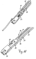
- Fig. 11 is shown closer to a generally designated 18 tie rod.
- This has a tension rod tube 19 and a tension roller 20 located within the tension rod tube 19.
- the tension rod 18 has bores 21 into which locking elements of the tension rod tube 19 are to be inserted.
- the tensioning roller 20 can be moved relative to the tensioning rod tube 19.
- the tension rod 18 has in its lower region a head piece 22 which is designed as a square and which is inserted into a corresponding square seat of the vehicle body in the assembled state of the parts.
- the side wall engages around a corner stanchion 11.
- a lever 23 is provided on the tensioning roller 20, which acts with the locking element (not shown). This is to be pressed in and also moved out and is secured by a locking ring 24.
- the side wall can be tensioned via the tension roller 20.
- the tie rod tube 19 has a slot-shaped receptacle, so that a corresponding piping can be inserted into the tension roller 20, so that all parts are to be arranged in a protected manner.
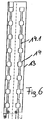
- FIG Fig. 13 can be seen as an angled profile body which can be pivoted about a horizontal axis 10.
- This portal beam 10 has various locking receptacles 10.1 arranged one above the other, which are secured by a locking finger 27 of door locking elements 8.1, 8.2.9.1, 9.2. are to be penetrated.
- the portal beam 10 itself is designed as a box with a front wall 10.2 and a rear wall 10.3 and an inner support rod 10.4, which can be gripped by the locking finger 27.
- the fact that it is designed to be pivotable means that it can also be used when building a commercial vehicle Fig.
Landscapes
- Engineering & Computer Science (AREA)
- Mechanical Engineering (AREA)
- Chemical & Material Sciences (AREA)
- Combustion & Propulsion (AREA)
- Transportation (AREA)
- Body Structure For Vehicles (AREA)
- Window Of Vehicle (AREA)
- Lock And Its Accessories (AREA)
- Power-Operated Mechanisms For Wings (AREA)
Claims (26)
- Construction de véhicule pour véhicules utilitaires avec une paroi frontale et une paroi arrière comportant des éléments de porte (8, 9) ainsi qu'un toit relevable pouvant être fixé sur des longerons et des traverses, s'étendant entre la paroi frontale et la paroi arrière ainsi que des parois latérales, lesquels sont en appui sur des ranchers corniers (11) avant et arrière réglables en hauteur et peuvent être transportés par des dispositifs de relevage (1, 2, 3, 4) dans différentes positions verticales, sachant que les éléments de porte (8, 9) peuvent être verrouillés par des éléments de blocage de porte (8.1, 8.2, 9.1, 9.2) présentant des doigts de verrouillage (27) sur une barre de portique (10) côté arrière qui présente plusieurs logements de verrouillage (10.1) disposés les uns au-dessus des autres pour le verrouillage des éléments de porte (8.9) dans différentes positions verticales du toit relevable, caractérisée en ce que la barre de portique (10) peut être fixée de manière à pouvoir pivoter autour d'un axe sensiblement horizontal (10.5) sur la construction de véhicule et peut être déplacée avec les ranchers corniers (11) arrière dans différentes positions verticales et est directement placée dans sa position de départ repivotée derrière le côté intérieur d'un battant de porte (8, 9), dans laquelle la barre de portique (10) est réalisée de manière à pouvoir coulisser parallèlement aux longerons vers l'avant et vers l'arrière au niveau de la paroi frontale et dans laquelle la barre de portique (10) est formée par un corps profilé angulaire doté d'un axe sensiblement horizontal (10.5) qui est décalé vers l'avant au niveau de la paroi frontale de la construction de véhicule par rapport au plan de la porte de l'élément de porte (8, 9), dans laquelle la barre de portique (10) est réalisée en forme de caisson et fermée vers l'intérieur du véhicule, avec une chambre de caisson (10.6) intérieure vers laquelle les logements de verrouillage (10.1) sont ouverts.
- Construction de véhicule selon la revendication 1, caractérisée en ce que la barre de portique (10) est associée à la barre de portique pour chaque élément de blocage de porte (8.1, 8.2, 9.1., 9.2) d'un élément de porte (8, 9).
- Construction de véhicule selon la revendication 1 ou 2, caractérisée en ce que la barre d'appui (10.4) est disposée à l'intérieur du caisson (10.6).
- Construction de véhicule selon l'une quelconque des revendications 1 à 3, caractérisée en ce que la barre de portique (10) rend étanche la construction de véhicule vers l'intérieur dans son état rabattu.
- Construction de véhicule selon l'une quelconque des revendications 1 à 4, caractérisée en ce que la barre de portique (10) est logée avec une articulation sur une traverse du véhicule utilitaire de telle manière qu'elle puisse être pivotée vers le haut et le bas autour du point de rotation de ce logement.
- Construction de véhicule selon l'une quelconque des revendications 1 à 5, caractérisée en ce qu'une barre d'appui (10.4) est logée de manière multiple dans des supports de palier (10.7) à l'intérieur du caisson (10.6) et forme la pièce antagoniste des doigts de verrouillage (27).
- Construction de véhicule selon l'une quelconque des revendications 1 à 6, caractérisée en ce que les dispositifs de relevage (1, 2) de deux ranchers corniers (11) avant et les dispositifs de relevage (3, 4) de deux ranchers corniers (11) arrière transfèrent après leur activation les ranchers corniers avant et arrière (11) dans leur position verticale maximale respective et les ranchers corniers avant et arrière (11) peuvent être abaissés après la désactivation des dispositifs de relevage (1, 2, 3, 4) sous l'effet de la force de gravité dans une position verticale réglable par un contre-palier respectif (17).
- Construction de véhicule selon la revendication 7, caractérisée en ce que les dispositifs de relevage (1, 2) de deux ranchers corniers avant et les dispositifs de relevage (3, 4) de deux ranchers corniers arrière (11) sont commutables de manière synchrone.
- Construction de véhicule selon la revendication 8, caractérisée en ce que les dispositifs de relevage (1, 2, 3, 4) sont réalisés comme des vérins hydrauliques et le fluide hydraulique peut être amené d'une pompe hydraulique (5) à l'un des dispositifs de relevage (1, 3) d'un rancher cornier (11) avant et arrière, et le fluide hydraulique est amené au second dispositif de relevage (2, 4) monté de manière synchrone du rancher cornier (11) avant ou du rancher cornier arrière (11) par le premier dispositif de relevage respectif (1, 3).
- Construction de véhicule selon la revendication 9, caractérisée en ce que les ranchers corniers (11) présentent chacun une pièce de poussée (12) mobile en hauteur et une pièce de poussée (12) blocable qui peut être reliée à une bielle (1.1, 2.1, 3.1, 4.1) d'un dispositif de relevage (1, 2, 3, 4).
- Construction de véhicule selon la revendication 10, caractérisée en ce que la pièce de poussée (12) est mobile le long d'un élément clé 813) d'un rancher cornier (11), sur lequel une clé (17) servant de contre-palier peut être bloquée de manière réglable en hauteur.
- Construction de véhicule selon la revendication 14, caractérisée en ce que la clé (17) est réalisée comme un élément coulissant et est guidée de manière mobile verticalement dans des guidages fendus (14.1) de l'élément clé (13).
- Construction de véhicule selon la revendication 11 ou 12, caractérisée en ce que la clé (17) peut être introduite dans des évidements percés (14) de l'élément clé (13).
- Construction de véhicule selon la revendication 13, caractérisée en ce que la clé présente des formations de blocage (17.2) pouvant être introduites dans des évidements percés (14) de l'élément clé (13).
- Construction de véhicule selon l'une quelconque des revendications 11 à 14, caractérisée en ce que la clé (17) peut être détachée à l'aide d'une poignée (17.5) de l'élément clé (13).
- Construction de véhicule selon l'une quelconque des revendications 10 à 15, caractérisée en ce que la pièce de poussée (12) intérieure présente une tôle de protection (16) disposée à distance de celle-ci qui peut être réglée verticalement avec la pièce de poussée (12) et recouvre la dimension de réglage en hauteur lors d'un réglage en hauteur.
- Construction de véhicule selon la revendication 16, caractérisée en ce que la tôle de protection 816) présente une étendue en longueur qui correspond au réglage en hauteur maximal du rancher cornier (11).
- Construction de véhicule selon l'une quelconque des revendications 1 à 17, caractérisée en ce que les parois latérales réalisées de manière flexible peuvent être fixées dans des tiges de serrage (18) qui sont réalisées de manière modifiable en longueur.
- Construction de véhicule selon la revendication 18, caractérisée en ce qu'une tige de serrage (18) présente un rouleau tendeur (20) guidé dans un tube de tige de serrage (17) et le rouleau tendeur (20) peut être bloqué avec le tube de tige de serrage (19) dans différentes positions longitudinales par un verrou.
- Construction de véhicule selon la revendication 19, caractérisée en ce que le tube de tige de serrage (19) présente des perçages (21), dans lesquels un élément de verrouillage mobile du rouleau tendeur (20) peut être introduit comme verrou.
- Construction de véhicule selon la revendication 20, caractérisée en ce que l'élément de verrouillage peut être bloqué par un circlip (24) mobile vers le haut et le bas dans le perçage (21).
- Construction de véhicule selon la revendication 20 ou 21, caractérisée en ce que l'élément de verrouillage peut être introduit à l'aide d'un levier rabattable (23) dans le perçage (21) et ressorti de celui-ci.
- Construction de véhicule selon l'une quelconque des revendications 20 à 22, caractérisée en ce que le rouleau tendeur (20) présente un guidage fendu pour le logement d'un bourrelet d'une paroi latérale flexible.
- Construction de véhicule selon l'une quelconque des revendications 21 à 23, caractérisée en ce que la tige de serrage (18) présente d'un côté une tête (22) réalisée comme un carré qui peut être introduite dans un logement carré correspondant de la construction de véhicule.
- Construction de véhicule selon l'une quelconque des revendications 21 à 24, caractérisée en ce qu'un élément de boucle agit sur la tige de serrage (18) afin de relever la tige de serrage (18) hors du logement carré de la construction de véhicule.
- Construction de véhicule selon l'une quelconque des revendications 1 à 25, caractérisée en ce que la paroi latérale recouvre un rancher cornier (11) à l'état fermé de la construction de véhicule.
Priority Applications (1)
| Application Number | Priority Date | Filing Date | Title |
|---|---|---|---|
| PL09008032T PL2151372T5 (pl) | 2008-07-31 | 2009-06-19 | Nadwozie do pojazdów użytkowych z wychylną belką portalową od strony tylnej tylnych skrzydeł drzwiowych |
Applications Claiming Priority (1)
| Application Number | Priority Date | Filing Date | Title |
|---|---|---|---|
| DE102008035768A DE102008035768A1 (de) | 2008-07-31 | 2008-07-31 | Fahrzeugaufbau für Nutzfahrzeuge |
Publications (3)
| Publication Number | Publication Date |
|---|---|
| EP2151372A1 EP2151372A1 (fr) | 2010-02-10 |
| EP2151372B1 EP2151372B1 (fr) | 2012-01-25 |
| EP2151372B2 true EP2151372B2 (fr) | 2020-02-12 |
Family
ID=41061308
Family Applications (1)
| Application Number | Title | Priority Date | Filing Date |
|---|---|---|---|
| EP09008032.6A Active EP2151372B2 (fr) | 2008-07-31 | 2009-06-19 | Plateforme pour véhicules utilitaires comprenant une poutre de soutien des portes arrières |
Country Status (6)
| Country | Link |
|---|---|
| EP (1) | EP2151372B2 (fr) |
| AT (1) | ATE542730T1 (fr) |
| DE (1) | DE102008035768A1 (fr) |
| DK (1) | DK2151372T4 (fr) |
| ES (1) | ES2378924T5 (fr) |
| PL (1) | PL2151372T5 (fr) |
Families Citing this family (2)
| Publication number | Priority date | Publication date | Assignee | Title |
|---|---|---|---|---|
| DE102012000843A1 (de) * | 2012-01-18 | 2013-07-18 | Fahrzeugwerk Bernard Krone Gmbh | Fahrzeugaufbau für Nutzfahrzeuge |
| DE102012107956A1 (de) | 2012-08-29 | 2014-03-27 | Kögel Trailer GmbH & Co. KG | Nutzfahrzeugaufbau mit einem höhenverstellbaren Dach und Nutzfahrzeug mit einem derartigen Nutzfahrzeugaufbau |
Family Cites Families (5)
| Publication number | Priority date | Publication date | Assignee | Title |
|---|---|---|---|---|
| DE29808621U1 (de) * | 1998-05-13 | 1998-07-30 | Hesterberg & Soehne Gmbh & Co | Hydraulischer Antrieb für ein Hubdach eines Nutzfahrzeugaufbaus |
| EP1136292A3 (fr) * | 2000-03-20 | 2003-03-26 | Aghito Sistemi S.r.l. | Chassis arrière, transversal et supérieur, et système de couplage autobloquant pour ouvertures de chargement de véhicules à cerceaux |
| DE10222998B4 (de) * | 2002-05-24 | 2006-05-04 | Schmitz Cargobull Ag | Rückwandtür mit Türsicherungselementen für ein Lastfahrzeug |
| DE102006004994B3 (de) * | 2006-02-01 | 2007-03-22 | F. Hesterberg & Söhne GmbH & Co KG | Rungensystem für Nutzfahrzeugaufbauten |
| DE202006008675U1 (de) * | 2006-05-30 | 2006-09-28 | Schmitz Cargobull Ag | Mit einer Flügeltür ausgestattete Rückwand eines Lastfahrzeugs |
-
2008
- 2008-07-31 DE DE102008035768A patent/DE102008035768A1/de not_active Withdrawn
-
2009
- 2009-06-19 PL PL09008032T patent/PL2151372T5/pl unknown
- 2009-06-19 ES ES09008032T patent/ES2378924T5/es active Active
- 2009-06-19 AT AT09008032T patent/ATE542730T1/de active
- 2009-06-19 EP EP09008032.6A patent/EP2151372B2/fr active Active
- 2009-06-19 DK DK09008032.6T patent/DK2151372T4/da active
Also Published As
| Publication number | Publication date |
|---|---|
| ES2378924T3 (es) | 2012-04-19 |
| DE102008035768A1 (de) | 2010-02-04 |
| DK2151372T4 (da) | 2020-05-18 |
| EP2151372A1 (fr) | 2010-02-10 |
| PL2151372T3 (pl) | 2012-07-31 |
| PL2151372T5 (pl) | 2020-09-07 |
| ES2378924T5 (es) | 2020-10-27 |
| DK2151372T3 (da) | 2012-05-07 |
| ATE542730T1 (de) | 2012-02-15 |
| EP2151372B1 (fr) | 2012-01-25 |
Similar Documents
| Publication | Publication Date | Title |
|---|---|---|
| EP0893302A2 (fr) | Plateau de chargement extensible pour un véhicule | |
| DE102006043655A1 (de) | Laderaumaufbau | |
| WO2006079137A1 (fr) | Dispositif de transfert de la paroi d'un contenant de transport entre une position fermee et une position ouverte et contenant de transport | |
| DE3236034A1 (de) | Kraftfahrzeug mit oeffenbarem dach | |
| EP1955932B1 (fr) | Mécanisme de fermeture pour une structure de véhicule | |
| DE102005021117A1 (de) | Kraftfahrzeug | |
| EP3590761B1 (fr) | Carrosserie de véhicule utilitaire | |
| EP2151372B2 (fr) | Plateforme pour véhicules utilitaires comprenant une poutre de soutien des portes arrières | |
| EP2151371A1 (fr) | Plateforme pour véhicules utilitaires équipée de ranchers réglables en hauteur | |
| EP2149490B2 (fr) | Plate-forme pour véhicules utilitaires avec ranchers à hauteur réglable | |
| EP2676824A2 (fr) | Structure pour le transports de biens | |
| DE10143934C1 (de) | Überrollschutzsystem für ein Kraftfahrzeug | |
| EP2708393B1 (fr) | Caisse de véhicule pour le transport de marchandises de transport empilables ou coulables | |
| DE102008035769B4 (de) | Fahrzeugaufbau für Nutzfahrzeuge | |
| EP2662240B1 (fr) | Montage de véhicule pour véhicules utilitaires | |
| EP1743611A1 (fr) | Rampe extensible pour véhicules de transport en commun | |
| EP3599119B1 (fr) | Structure de bâche résistante à l'humidité | |
| EP2428434B1 (fr) | Mécanisme de fermeture pour une structure de véhicule | |
| DE102004003564B4 (de) | Mobile Transport- und Aufbewahrungseinheit | |
| EP2684782B1 (fr) | Structure pour le transports de biens | |
| DE202008017440U1 (de) | Fahrzeugaufbau für Nutzfahrzeuge | |
| EP3275710B1 (fr) | Articulation a coulisseau | |
| EP3523161B1 (fr) | Véhicule, notamment véhicule d'intérêt général, comprenant un système de chargement | |
| DE202006010095U1 (de) | Nutzfahrzeug, vorzugsweise für Campingzwecke | |
| DE202014100949U1 (de) | Nutzfahrzeug mit mindestens einer Seitenplane |
Legal Events
| Date | Code | Title | Description |
|---|---|---|---|
| PUAI | Public reference made under article 153(3) epc to a published international application that has entered the european phase |
Free format text: ORIGINAL CODE: 0009012 |
|
| 17P | Request for examination filed |
Effective date: 20091022 |
|
| AK | Designated contracting states |
Kind code of ref document: A1 Designated state(s): AT BE BG CH CY CZ DE DK EE ES FI FR GB GR HR HU IE IS IT LI LT LU LV MC MK MT NL NO PL PT RO SE SI SK TR |
|
| AX | Request for extension of the european patent |
Extension state: AL BA RS |
|
| GRAP | Despatch of communication of intention to grant a patent |
Free format text: ORIGINAL CODE: EPIDOSNIGR1 |
|
| GRAS | Grant fee paid |
Free format text: ORIGINAL CODE: EPIDOSNIGR3 |
|
| GRAA | (expected) grant |
Free format text: ORIGINAL CODE: 0009210 |
|
| AK | Designated contracting states |
Kind code of ref document: B1 Designated state(s): AT BE BG CH CY CZ DE DK EE ES FI FR GB GR HR HU IE IS IT LI LT LU LV MC MK MT NL NO PL PT RO SE SI SK TR |
|
| REG | Reference to a national code |
Ref country code: GB Ref legal event code: FG4D Free format text: NOT ENGLISH |
|
| REG | Reference to a national code |
Ref country code: CH Ref legal event code: EP |
|
| REG | Reference to a national code |
Ref country code: AT Ref legal event code: REF Ref document number: 542730 Country of ref document: AT Kind code of ref document: T Effective date: 20120215 |
|
| REG | Reference to a national code |
Ref country code: IE Ref legal event code: FG4D |
|
| REG | Reference to a national code |
Ref country code: DE Ref legal event code: R096 Ref document number: 502009002529 Country of ref document: DE Effective date: 20120322 |
|
| REG | Reference to a national code |
Ref country code: ES Ref legal event code: FG2A Ref document number: 2378924 Country of ref document: ES Kind code of ref document: T3 Effective date: 20120419 |
|
| REG | Reference to a national code |
Ref country code: SE Ref legal event code: TRGR |
|
| REG | Reference to a national code |
Ref country code: NL Ref legal event code: T3 |
|
| REG | Reference to a national code |
Ref country code: DK Ref legal event code: T3 |
|
| LTIE | Lt: invalidation of european patent or patent extension |
Effective date: 20120125 |
|
| PG25 | Lapsed in a contracting state [announced via postgrant information from national office to epo] |
Ref country code: BG Free format text: LAPSE BECAUSE OF FAILURE TO SUBMIT A TRANSLATION OF THE DESCRIPTION OR TO PAY THE FEE WITHIN THE PRESCRIBED TIME-LIMIT Effective date: 20120425 Ref country code: IS Free format text: LAPSE BECAUSE OF FAILURE TO SUBMIT A TRANSLATION OF THE DESCRIPTION OR TO PAY THE FEE WITHIN THE PRESCRIBED TIME-LIMIT Effective date: 20120525 Ref country code: NO Free format text: LAPSE BECAUSE OF FAILURE TO SUBMIT A TRANSLATION OF THE DESCRIPTION OR TO PAY THE FEE WITHIN THE PRESCRIBED TIME-LIMIT Effective date: 20120425 Ref country code: HR Free format text: LAPSE BECAUSE OF FAILURE TO SUBMIT A TRANSLATION OF THE DESCRIPTION OR TO PAY THE FEE WITHIN THE PRESCRIBED TIME-LIMIT Effective date: 20120125 Ref country code: LT Free format text: LAPSE BECAUSE OF FAILURE TO SUBMIT A TRANSLATION OF THE DESCRIPTION OR TO PAY THE FEE WITHIN THE PRESCRIBED TIME-LIMIT Effective date: 20120125 |
|
| REG | Reference to a national code |
Ref country code: PL Ref legal event code: T3 |
|
| REG | Reference to a national code |
Ref country code: IE Ref legal event code: FD4D |
|
| PG25 | Lapsed in a contracting state [announced via postgrant information from national office to epo] |
Ref country code: FI Free format text: LAPSE BECAUSE OF FAILURE TO SUBMIT A TRANSLATION OF THE DESCRIPTION OR TO PAY THE FEE WITHIN THE PRESCRIBED TIME-LIMIT Effective date: 20120125 Ref country code: LV Free format text: LAPSE BECAUSE OF FAILURE TO SUBMIT A TRANSLATION OF THE DESCRIPTION OR TO PAY THE FEE WITHIN THE PRESCRIBED TIME-LIMIT Effective date: 20120125 Ref country code: PT Free format text: LAPSE BECAUSE OF FAILURE TO SUBMIT A TRANSLATION OF THE DESCRIPTION OR TO PAY THE FEE WITHIN THE PRESCRIBED TIME-LIMIT Effective date: 20120525 Ref country code: GR Free format text: LAPSE BECAUSE OF FAILURE TO SUBMIT A TRANSLATION OF THE DESCRIPTION OR TO PAY THE FEE WITHIN THE PRESCRIBED TIME-LIMIT Effective date: 20120426 |
|
| PG25 | Lapsed in a contracting state [announced via postgrant information from national office to epo] |
Ref country code: CY Free format text: LAPSE BECAUSE OF FAILURE TO SUBMIT A TRANSLATION OF THE DESCRIPTION OR TO PAY THE FEE WITHIN THE PRESCRIBED TIME-LIMIT Effective date: 20120125 |
|
| PG25 | Lapsed in a contracting state [announced via postgrant information from national office to epo] |
Ref country code: RO Free format text: LAPSE BECAUSE OF FAILURE TO SUBMIT A TRANSLATION OF THE DESCRIPTION OR TO PAY THE FEE WITHIN THE PRESCRIBED TIME-LIMIT Effective date: 20120125 Ref country code: IE Free format text: LAPSE BECAUSE OF FAILURE TO SUBMIT A TRANSLATION OF THE DESCRIPTION OR TO PAY THE FEE WITHIN THE PRESCRIBED TIME-LIMIT Effective date: 20120125 Ref country code: SI Free format text: LAPSE BECAUSE OF FAILURE TO SUBMIT A TRANSLATION OF THE DESCRIPTION OR TO PAY THE FEE WITHIN THE PRESCRIBED TIME-LIMIT Effective date: 20120125 Ref country code: CZ Free format text: LAPSE BECAUSE OF FAILURE TO SUBMIT A TRANSLATION OF THE DESCRIPTION OR TO PAY THE FEE WITHIN THE PRESCRIBED TIME-LIMIT Effective date: 20120125 Ref country code: EE Free format text: LAPSE BECAUSE OF FAILURE TO SUBMIT A TRANSLATION OF THE DESCRIPTION OR TO PAY THE FEE WITHIN THE PRESCRIBED TIME-LIMIT Effective date: 20120125 |
|
| PLBI | Opposition filed |
Free format text: ORIGINAL CODE: 0009260 |
|
| PLAX | Notice of opposition and request to file observation + time limit sent |
Free format text: ORIGINAL CODE: EPIDOSNOBS2 |
|
| PG25 | Lapsed in a contracting state [announced via postgrant information from national office to epo] |
Ref country code: SK Free format text: LAPSE BECAUSE OF FAILURE TO SUBMIT A TRANSLATION OF THE DESCRIPTION OR TO PAY THE FEE WITHIN THE PRESCRIBED TIME-LIMIT Effective date: 20120125 |
|
| 26 | Opposition filed |
Opponent name: SCHMITZ CARGOBULL AG Effective date: 20121025 Opponent name: KOEGEL TRAILER GMBH & CO. KG Effective date: 20121025 |
|
| REG | Reference to a national code |
Ref country code: DE Ref legal event code: R026 Ref document number: 502009002529 Country of ref document: DE Effective date: 20121025 |
|
| PG25 | Lapsed in a contracting state [announced via postgrant information from national office to epo] |
Ref country code: MC Free format text: LAPSE BECAUSE OF NON-PAYMENT OF DUE FEES Effective date: 20120630 |
|
| PG25 | Lapsed in a contracting state [announced via postgrant information from national office to epo] |
Ref country code: MK Free format text: LAPSE BECAUSE OF FAILURE TO SUBMIT A TRANSLATION OF THE DESCRIPTION OR TO PAY THE FEE WITHIN THE PRESCRIBED TIME-LIMIT Effective date: 20120125 |
|
| PLBB | Reply of patent proprietor to notice(s) of opposition received |
Free format text: ORIGINAL CODE: EPIDOSNOBS3 |
|
| PG25 | Lapsed in a contracting state [announced via postgrant information from national office to epo] |
Ref country code: MT Free format text: LAPSE BECAUSE OF FAILURE TO SUBMIT A TRANSLATION OF THE DESCRIPTION OR TO PAY THE FEE WITHIN THE PRESCRIBED TIME-LIMIT Effective date: 20120125 |
|
| REG | Reference to a national code |
Ref country code: CH Ref legal event code: PL |
|
| PG25 | Lapsed in a contracting state [announced via postgrant information from national office to epo] |
Ref country code: CH Free format text: LAPSE BECAUSE OF NON-PAYMENT OF DUE FEES Effective date: 20130630 Ref country code: LI Free format text: LAPSE BECAUSE OF NON-PAYMENT OF DUE FEES Effective date: 20130630 |
|
| PG25 | Lapsed in a contracting state [announced via postgrant information from national office to epo] |
Ref country code: LU Free format text: LAPSE BECAUSE OF NON-PAYMENT OF DUE FEES Effective date: 20120619 |
|
| PG25 | Lapsed in a contracting state [announced via postgrant information from national office to epo] |
Ref country code: HU Free format text: LAPSE BECAUSE OF FAILURE TO SUBMIT A TRANSLATION OF THE DESCRIPTION OR TO PAY THE FEE WITHIN THE PRESCRIBED TIME-LIMIT Effective date: 20090619 |
|
| REG | Reference to a national code |
Ref country code: FR Ref legal event code: PLFP Year of fee payment: 8 |
|
| APBM | Appeal reference recorded |
Free format text: ORIGINAL CODE: EPIDOSNREFNO |
|
| APBP | Date of receipt of notice of appeal recorded |
Free format text: ORIGINAL CODE: EPIDOSNNOA2O |
|
| APAH | Appeal reference modified |
Free format text: ORIGINAL CODE: EPIDOSCREFNO |
|
| APBQ | Date of receipt of statement of grounds of appeal recorded |
Free format text: ORIGINAL CODE: EPIDOSNNOA3O |
|
| REG | Reference to a national code |
Ref country code: FR Ref legal event code: PLFP Year of fee payment: 9 |
|
| REG | Reference to a national code |
Ref country code: FR Ref legal event code: PLFP Year of fee payment: 10 |
|
| APBU | Appeal procedure closed |
Free format text: ORIGINAL CODE: EPIDOSNNOA9O |
|
| PUAH | Patent maintained in amended form |
Free format text: ORIGINAL CODE: 0009272 |
|
| STAA | Information on the status of an ep patent application or granted ep patent |
Free format text: STATUS: PATENT MAINTAINED AS AMENDED |
|
| 27A | Patent maintained in amended form |
Effective date: 20200212 |
|
| AK | Designated contracting states |
Kind code of ref document: B2 Designated state(s): AT BE BG CH CY CZ DE DK EE ES FI FR GB GR HR HU IE IS IT LI LT LU LV MC MK MT NL NO PL PT RO SE SI SK TR |
|
| REG | Reference to a national code |
Ref country code: DE Ref legal event code: R102 Ref document number: 502009002529 Country of ref document: DE |
|
| REG | Reference to a national code |
Ref country code: DK Ref legal event code: T4 Effective date: 20200513 |
|
| REG | Reference to a national code |
Ref country code: NL Ref legal event code: FP |
|
| REG | Reference to a national code |
Ref country code: SE Ref legal event code: RPEO |
|
| REG | Reference to a national code |
Ref country code: ES Ref legal event code: DC2A Ref document number: 2378924 Country of ref document: ES Kind code of ref document: T5 Effective date: 20201027 |
|
| P01 | Opt-out of the competence of the unified patent court (upc) registered |
Effective date: 20230518 |
|
| PGFP | Annual fee paid to national office [announced via postgrant information from national office to epo] |
Ref country code: NL Payment date: 20230620 Year of fee payment: 15 Ref country code: FR Payment date: 20230622 Year of fee payment: 15 Ref country code: DK Payment date: 20230621 Year of fee payment: 15 Ref country code: DE Payment date: 20230620 Year of fee payment: 15 |
|
| PGFP | Annual fee paid to national office [announced via postgrant information from national office to epo] |
Ref country code: TR Payment date: 20230613 Year of fee payment: 15 Ref country code: SE Payment date: 20230622 Year of fee payment: 15 Ref country code: PL Payment date: 20230607 Year of fee payment: 15 Ref country code: AT Payment date: 20230616 Year of fee payment: 15 |
|
| PGFP | Annual fee paid to national office [announced via postgrant information from national office to epo] |
Ref country code: BE Payment date: 20230619 Year of fee payment: 15 |
|
| PGFP | Annual fee paid to national office [announced via postgrant information from national office to epo] |
Ref country code: IT Payment date: 20230630 Year of fee payment: 15 Ref country code: GB Payment date: 20230622 Year of fee payment: 15 Ref country code: ES Payment date: 20230719 Year of fee payment: 15 |