EP2151332A1 - Pneumatic tire - Google Patents
Pneumatic tire Download PDFInfo
- Publication number
- EP2151332A1 EP2151332A1 EP08764742A EP08764742A EP2151332A1 EP 2151332 A1 EP2151332 A1 EP 2151332A1 EP 08764742 A EP08764742 A EP 08764742A EP 08764742 A EP08764742 A EP 08764742A EP 2151332 A1 EP2151332 A1 EP 2151332A1
- Authority
- EP
- European Patent Office
- Prior art keywords
- tire
- carcass
- pneumatic tire
- cord
- point
- Prior art date
- Legal status (The legal status is an assumption and is not a legal conclusion. Google has not performed a legal analysis and makes no representation as to the accuracy of the status listed.)
- Granted
Links
Images



Classifications
-
- B—PERFORMING OPERATIONS; TRANSPORTING
- B60—VEHICLES IN GENERAL
- B60C—VEHICLE TYRES; TYRE INFLATION; TYRE CHANGING; CONNECTING VALVES TO INFLATABLE ELASTIC BODIES IN GENERAL; DEVICES OR ARRANGEMENTS RELATED TO TYRES
- B60C9/00—Reinforcements or ply arrangement of pneumatic tyres
- B60C9/02—Carcasses
- B60C9/04—Carcasses the reinforcing cords of each carcass ply arranged in a substantially parallel relationship
-
- B—PERFORMING OPERATIONS; TRANSPORTING
- B60—VEHICLES IN GENERAL
- B60C—VEHICLE TYRES; TYRE INFLATION; TYRE CHANGING; CONNECTING VALVES TO INFLATABLE ELASTIC BODIES IN GENERAL; DEVICES OR ARRANGEMENTS RELATED TO TYRES
- B60C11/00—Tyre tread bands; Tread patterns; Anti-skid inserts
-
- B—PERFORMING OPERATIONS; TRANSPORTING
- B60—VEHICLES IN GENERAL
- B60C—VEHICLE TYRES; TYRE INFLATION; TYRE CHANGING; CONNECTING VALVES TO INFLATABLE ELASTIC BODIES IN GENERAL; DEVICES OR ARRANGEMENTS RELATED TO TYRES
- B60C11/00—Tyre tread bands; Tread patterns; Anti-skid inserts
- B60C11/0083—Tyre tread bands; Tread patterns; Anti-skid inserts characterised by the curvature of the tyre tread
-
- B—PERFORMING OPERATIONS; TRANSPORTING
- B60—VEHICLES IN GENERAL
- B60C—VEHICLE TYRES; TYRE INFLATION; TYRE CHANGING; CONNECTING VALVES TO INFLATABLE ELASTIC BODIES IN GENERAL; DEVICES OR ARRANGEMENTS RELATED TO TYRES
- B60C15/00—Tyre beads, e.g. ply turn-up or overlap
- B60C15/0009—Tyre beads, e.g. ply turn-up or overlap features of the carcass terminal portion
- B60C15/0036—Tyre beads, e.g. ply turn-up or overlap features of the carcass terminal portion with high ply turn-up, i.e. folded around the bead core and terminating radially above the point of maximum section width
- B60C15/0045—Tyre beads, e.g. ply turn-up or overlap features of the carcass terminal portion with high ply turn-up, i.e. folded around the bead core and terminating radially above the point of maximum section width with ply turn-up up to the belt edges, i.e. folded around the bead core and extending to the belt edges
-
- B—PERFORMING OPERATIONS; TRANSPORTING
- B60—VEHICLES IN GENERAL
- B60C—VEHICLE TYRES; TYRE INFLATION; TYRE CHANGING; CONNECTING VALVES TO INFLATABLE ELASTIC BODIES IN GENERAL; DEVICES OR ARRANGEMENTS RELATED TO TYRES
- B60C15/00—Tyre beads, e.g. ply turn-up or overlap
- B60C15/02—Seating or securing beads on rims
- B60C15/024—Bead contour, e.g. lips, grooves, or ribs
- B60C15/0242—Bead contour, e.g. lips, grooves, or ribs with bead extensions located radially outside the rim flange position, e.g. rim flange protectors
-
- B—PERFORMING OPERATIONS; TRANSPORTING
- B60—VEHICLES IN GENERAL
- B60C—VEHICLE TYRES; TYRE INFLATION; TYRE CHANGING; CONNECTING VALVES TO INFLATABLE ELASTIC BODIES IN GENERAL; DEVICES OR ARRANGEMENTS RELATED TO TYRES
- B60C15/00—Tyre beads, e.g. ply turn-up or overlap
- B60C15/06—Flipper strips, fillers, or chafing strips and reinforcing layers for the construction of the bead
-
- B—PERFORMING OPERATIONS; TRANSPORTING
- B60—VEHICLES IN GENERAL
- B60C—VEHICLE TYRES; TYRE INFLATION; TYRE CHANGING; CONNECTING VALVES TO INFLATABLE ELASTIC BODIES IN GENERAL; DEVICES OR ARRANGEMENTS RELATED TO TYRES
- B60C17/00—Tyres characterised by means enabling restricted operation in damaged or deflated condition; Accessories therefor
- B60C17/0009—Tyres characterised by means enabling restricted operation in damaged or deflated condition; Accessories therefor comprising sidewall rubber inserts, e.g. crescent shaped inserts
-
- B—PERFORMING OPERATIONS; TRANSPORTING
- B60—VEHICLES IN GENERAL
- B60C—VEHICLE TYRES; TYRE INFLATION; TYRE CHANGING; CONNECTING VALVES TO INFLATABLE ELASTIC BODIES IN GENERAL; DEVICES OR ARRANGEMENTS RELATED TO TYRES
- B60C3/00—Tyres characterised by the transverse section
- B60C3/04—Tyres characterised by the transverse section characterised by the relative dimensions of the section, e.g. low profile
-
- B—PERFORMING OPERATIONS; TRANSPORTING
- B60—VEHICLES IN GENERAL
- B60C—VEHICLE TYRES; TYRE INFLATION; TYRE CHANGING; CONNECTING VALVES TO INFLATABLE ELASTIC BODIES IN GENERAL; DEVICES OR ARRANGEMENTS RELATED TO TYRES
- B60C9/00—Reinforcements or ply arrangement of pneumatic tyres
- B60C9/02—Carcasses
- B60C9/04—Carcasses the reinforcing cords of each carcass ply arranged in a substantially parallel relationship
- B60C9/08—Carcasses the reinforcing cords of each carcass ply arranged in a substantially parallel relationship the cords extend transversely from bead to bead, i.e. radial ply
-
- D—TEXTILES; PAPER
- D02—YARNS; MECHANICAL FINISHING OF YARNS OR ROPES; WARPING OR BEAMING
- D02G—CRIMPING OR CURLING FIBRES, FILAMENTS, THREADS, OR YARNS; YARNS OR THREADS
- D02G3/00—Yarns or threads, e.g. fancy yarns; Processes or apparatus for the production thereof, not otherwise provided for
- D02G3/44—Yarns or threads characterised by the purpose for which they are designed
- D02G3/48—Tyre cords
-
- B—PERFORMING OPERATIONS; TRANSPORTING
- B60—VEHICLES IN GENERAL
- B60C—VEHICLE TYRES; TYRE INFLATION; TYRE CHANGING; CONNECTING VALVES TO INFLATABLE ELASTIC BODIES IN GENERAL; DEVICES OR ARRANGEMENTS RELATED TO TYRES
- B60C9/00—Reinforcements or ply arrangement of pneumatic tyres
- B60C9/02—Carcasses
- B60C9/04—Carcasses the reinforcing cords of each carcass ply arranged in a substantially parallel relationship
- B60C2009/0416—Physical properties or dimensions of the carcass cords
- B60C2009/0425—Diameters of the cords; Linear density thereof
-
- B—PERFORMING OPERATIONS; TRANSPORTING
- B60—VEHICLES IN GENERAL
- B60C—VEHICLE TYRES; TYRE INFLATION; TYRE CHANGING; CONNECTING VALVES TO INFLATABLE ELASTIC BODIES IN GENERAL; DEVICES OR ARRANGEMENTS RELATED TO TYRES
- B60C9/00—Reinforcements or ply arrangement of pneumatic tyres
- B60C9/02—Carcasses
- B60C9/04—Carcasses the reinforcing cords of each carcass ply arranged in a substantially parallel relationship
- B60C2009/0416—Physical properties or dimensions of the carcass cords
- B60C2009/0441—Density in width direction
-
- B—PERFORMING OPERATIONS; TRANSPORTING
- B60—VEHICLES IN GENERAL
- B60C—VEHICLE TYRES; TYRE INFLATION; TYRE CHANGING; CONNECTING VALVES TO INFLATABLE ELASTIC BODIES IN GENERAL; DEVICES OR ARRANGEMENTS RELATED TO TYRES
- B60C9/00—Reinforcements or ply arrangement of pneumatic tyres
- B60C9/02—Carcasses
- B60C9/04—Carcasses the reinforcing cords of each carcass ply arranged in a substantially parallel relationship
- B60C2009/0416—Physical properties or dimensions of the carcass cords
- B60C2009/0466—Twist structures
-
- B—PERFORMING OPERATIONS; TRANSPORTING
- B60—VEHICLES IN GENERAL
- B60C—VEHICLE TYRES; TYRE INFLATION; TYRE CHANGING; CONNECTING VALVES TO INFLATABLE ELASTIC BODIES IN GENERAL; DEVICES OR ARRANGEMENTS RELATED TO TYRES
- B60C9/00—Reinforcements or ply arrangement of pneumatic tyres
- B60C9/02—Carcasses
- B60C9/04—Carcasses the reinforcing cords of each carcass ply arranged in a substantially parallel relationship
- B60C2009/0475—Particular materials of the carcass cords
-
- D—TEXTILES; PAPER
- D10—INDEXING SCHEME ASSOCIATED WITH SUBLASSES OF SECTION D, RELATING TO TEXTILES
- D10B—INDEXING SCHEME ASSOCIATED WITH SUBLASSES OF SECTION D, RELATING TO TEXTILES
- D10B2331/00—Fibres made from polymers obtained otherwise than by reactions only involving carbon-to-carbon unsaturated bonds, e.g. polycondensation products
- D10B2331/02—Fibres made from polymers obtained otherwise than by reactions only involving carbon-to-carbon unsaturated bonds, e.g. polycondensation products polyamides
- D10B2331/021—Fibres made from polymers obtained otherwise than by reactions only involving carbon-to-carbon unsaturated bonds, e.g. polycondensation products polyamides aromatic polyamides, e.g. aramides
Definitions
- the present invention relates to a pneumatic tire which is suitable as, for example, a passenger car tire and a motorcycle tire, particularly as a runflat tire, and which has various tire performances improved with achieving weight reduction.
- a runflat tire capable of traveling for a relatively long distance in a deflated condition that the tire loses air pressure due to a puncture
- a tire of so-called side-reinforced type wherein a side-reinforcing rubber layer having a crescent-shaped cross section is disposed in each sidewall portion
- a plurality of carcass plies are used in order to enhance a load-supporting ability.
- a rayon fiber cord which has a good heat resistance is used as a carcass cord in order to secure a durability in runflat mode, since the tire temperature in runflat mode is very high as compared with that during normal running in the inflated state.
- Tires having the above-mentioned structure have a necessary minimum durability, but further improvement in runflat durability and steering stability is strongly desired from the viewpoints of recent demands for high running speed and long running distance in runflat mode.
- the present invention is based on using, as a carcass cord, an aramid fiber cord which has a heat resistance superior to that of a rayon fiber cord and a high elasticity.
- the invention as claimed in claim 1 of the present application is directed to a pneumatic tire including a carcass extending from a tread portion to bead cores in bead portions through sidewall portions, and a tread-reinforcing cord layer disposed radially outward of the carcass and in the tread portion, and is characterized in that in the meridian cross section including the rotational axis of the tire in a normal inner pressure condition that the tire is mounted on a normal rim and inflated to a normal inner pressure, the outer surface of the tire has a curved profile composed of a plurality of circular arcs having different radii of curvature, the carcass comprises a carcass ply in which carcass cords are arranged at an angle of 45 to 90° with respect to a circumferential direction of the tire and are covered with a topping rubber, and an aramid fiber is used for the carcass cords.
- the invention as claimed in claim 2 is characterized in that the carcass cords have a two-bundle twisted structure that two bundles of first-twisted filaments are subjected to final twist.
- the invention as claimed in claim 4 is characterized in that the twist factor T of the carcass cords is from 0.6 to 0.7.
- the invention as claimed in claim 5 is characterized in that the topping rubber of the carcass ply has a complex modulus E* of 5 to 13 MPa.
- the invention as claimed in claim 6 is characterized in that the pneumatic tire is a runflat tire provided in the sidewall portions with side-reinforcing rubber layers each having a cross section of such a crescent-shape that it has the maximum thickness at a center portion thereof and extends radially inward and outward from the center portion with decreasing its thickness.
- the invention as claimed in claim 7 is characterized in that the outer surface of the tire has a curved profile composed of a plurality of circular arcs having radii of curvature which gradually decrease from a tire equator point CP at which the outer surface of the tire intersects with a tire equator plane C toward a ground contact edge side.
- the invention as claimed in claim 8 is characterized in that the outer surface of the tire has a profile such that the radius of curvature of the outer surface of the tire gradually decreases from the tire equator point CP to a point P, in which the point P denotes a point on the tire outer surface which is apart from the tire equator plane C by a distance SP of 45 % of the maximum section width SW of the tire, and the profile satisfies the following equations: 0.05 ⁇ Y ⁇ 60 / SH ⁇ 0.1 0.1 ⁇ Y ⁇ 75 / SH ⁇ 0.2 ⁇ Y ⁇ 90 / SH ⁇ 0.4 0.4 ⁇ Y ⁇ 100 / SH ⁇ 0.7 in which Y60, Y75, Y90 and Y100 denote radial distances between the tire equator point CP and each of points on the tire outer surface apart from the tire equator plane C by distances X60, X75, X90 and X100 of 60%, 7
- the invention as claimed in claim 9 is characterized in that the outer surface of the tire has a profile such that the radius of curvature measured on a ground contact edge side is larger than that measured at the tire equator point CP at which the outer surface of the tire intersects with the tire equator plane C.
- normal rim as used herein means a rim defined for every tire in a standardizing system on which the tire is based and, for example, denotes “standard rim” in JATMA, "design rim” in TRA and “measuring rim” in ETRTO.
- normal inner pressure as used herein means an air pressure defined for every tire in a standardizing system and, for example, denotes the maximum air pressure in JATMA, the maximum value recited in the table of "Tire Load Limits at Various Cold Inflation Pressures" in TRA, and the “Inflation Pressure” in ETRTO, provided that in case of tires for passenger cars, the "normal inner pressure” is 180 kPa.
- complex modulus denotes a value measured with a viscoelasticity spectrometer under the conditions of measuring temperature 70°C, initial tension 1,000 g, dynamic strain ⁇ 0.03%, and frequency 10 Hz.
- an aramid fiber cord superior particularly in heat resistance is used as a carcass cord. Therefore, damages of the cord owing to temperature elevation during ranflat running can be suppressed. Further, since the aramid fiber cord has a high elasticity and accordingly can enhance the load-supporting ability, deformation of the tire in runflat running can be reduced while achieving decrease in the number of plies (weight reduction). Accordingly, in cooperation with the enhancement of heat resistance, the runflat durability can be enhanced. Further, the steering stability in runflat mode can be improved, thus achieving high running speed and long running distance in runflat mode.
- the steering stability can be improved to achieve high running speed and high performances in normal running, with achieving weight reduction.
- Fig. 1 is a meridian cross section view of a tire in the normal inner pressure condition wherein a tire 1 according to the present invention is a runflat tire 1A.
- the runflat tire 1A in this embodiment includes a carcass 6 that extends from a tread portion 2 to bead cores 5 in bead portions 4 through sidewall portions 3, and a tread-reinforcing cord layer 7 that is disposed radially outward of the carcass 6 in the tread portion 2.
- the carcass 6 comprises at least one carcass ply in which carcass cords are disposed at an angle of 45 to 90° with respect to the tire circumferential direction and covered with a topping rubber.
- a carcass composed of a single carcass ply 6A of carcass cords arranged at an angle of 80 to 90°.
- the carcass ply 6A is composed of a ply body portion 6a that extends between the bead cores 5, 5, and ply turnup portions 6b that are continuous with the ply body portion 6a and are turned up around the bead cores 5 from the axially inside to the axially outside of the tire.
- a bead apex rubber 8 for reinforcing the bead portion which is for example made of a hard rubber having a rubber hardness of 65 to 98, is disposed between the ply body portion 6a and the ply turnup portion 6b to radially outwardly extend from the bead core 5 in a tapered manner.
- the "rubber hardness” as used herein denotes a hardness measured by a durometer type A at 23°C. Radial height "ha" of the bead apex rubber 8 from a bead base line BL is not particularly limited.
- the height "ha" of the bead apex rubber 8 is from 10 to 60 %, especially 20 to 50 %, of the section height SH of the tire.
- the carcass ply 6A has a so-called high turnup structure wherein the ply turnup portion 6b of the carcass 6 extends radially outwardly beyond the radially outer end of the bead apex rubber 8 and terminates so that outer end 6be of the turnup portion 6b is sandwiched between the ply body portion 6a and the tread-reinforcing cord layer 7.
- This structure can effectively reinforce the sidewall portion 3 by the use of single carcass ply 6A. Also, since the outer end 6be of the ply turnup portion 6b is located apart from the sidewall portion 3 that is greatly bent during runflat running, damages occurring from the outer end 6be can be suitably suppressed.
- the axial width EW of the overlapping part of the turnup portion 6b with the tread-reinforcing cord layer 7 is preferably at least 5 mm, more preferably at least 10 mm. It is also preferably at most 40 mm, more preferably at most 30 mm, from the viewpoint of weight reduction. In case of forming the carcass 6 using a plurality of carcass plies, it is preferable that at least one carcass ply has such a high turnup structure.
- the tread-reinforcing cord layer 7 in this embodiment comprises a belt 9 superposed on the carcass 6, and a band 10 superposed outward of the belt 9.
- the belt 9 comprises at least two belt plies (in this embodiment, two belt plies 9A and 9B) in each of which belt cords are arranged at an angle, for example, of 10 to 45° with respect to the tire circumferential direction and covered with a topping rubber.
- the belt plies are stacked so that the belt cords in one ply crosses the cords in the other belt ply, whereby the rigidity of the belt is enhanced to strongly reinforce the tread portion 2 over approximately full width thereof by a hoop effect.
- the band 10 comprises at least one band ply in which a band cord is spirally wound at an angle of 5° or less with respect to the tire circumferential direction and covered with a topping rubber.
- the band serves to bind the belt 9, thereby enhancing the steering stability, high speed durability and the like.
- As the band ply are adoptable a pair of right and left edge band plies which are disposed to cover only axially outer edge portions of the belt 9, a full band ply which covers approximately full width of the belt 9, and a combination of them.
- the band 10 shown in this embodiment comprises a single full band ply.
- the tread-reinforcing cord layer 7 may be formed of only belt 9 or only band 10.
- side-reinforcing rubber layers 11 are disposed in the sidewall portions 3.
- the side-reinforcing rubber layer 11 has a cross section of such a crescent-shape that it has the maximum thickness at its center portion 11a and extends radially from the center portion 11 a toward both a radially inner end 11i and a radially outer end 11o with gradually decreasing the thickness, respectively.
- the inner end 11i is located radially inward of the radially outer end of the bead apex rubber 8, and the outer end 11o is located axially inward of an outer end 7e of the tread-reinforcing cord layer 7.
- the radial width Wi of an overlapping part of the side-reinforcing rubber layer 11 with the bead apex rubber 8 is from 5 to 50 mm
- the axial width Wo of an overlapping part of the side-reinforcing rubber layer 11 with the tread-reinforcing cord layer 7 is from 0 to 50 mm, whereby occurrence of a difference in rigidity at the outer and inner ends 11o and 11i of the reinforcing rubber layer 11 is controlled.
- the side-reinforcing rubber layer 11 is disposed axially inward (on a tire cavity side) of the ply body portion 6a of the carcass 6 and, therefore, when the sidewall portion 3 is subject to a flexural deformation, mainly a compressive load acts on the side-reinforcing rubber layer 11 and a tensile load acts on the carcass ply 6A which includes a cord material. Since a rubber material is resistant to the compressive load and a cord material is resistant to the tensile load, the configuration as mentioned above of the side-reinforcing rubber layer 11 can efficiently enhance the flexural rigidity of the sidewall portion 3, thus effectively decreasing a vertical flex of a tire in runflat mode.
- the side-reinforcing rubber layer 11 has a rubber hardness of at least 60, especially at least 65. If the hardness is less than 60, the compressive strain in runflat mode is large, so sufficient runflat performances are not obtained. If the hardness is too high, the longitudinal spring constant of a tire excessively increases to lower the ride comfort. From such points of view, it is preferable that the hardness of the side-reinforcing rubber layer 11 is at most 90, especially at most 80.
- the maximum thickness "t" of the side-reinforcing rubber layer 11 is suitably selected depending on tire size, kind of the tire and the like. In case of tires for passenger cars, the maximum thickness "t" is usually from 5 to 20 mm.
- a rim-protecting rib 12 is convexly disposed in the bead portion 4.
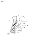
- the rim-protecting rib 12 is, as shown in Fig. 2 , a rib projecting from a base profile line "j" to cover a rim flange JF. It has a trapezoidal cross section which is enclosed by a projecting face 12c which projects most axially outwardly, a radially inner slope 12i which smoothly continues from the projecting face 12c to the axially outer surface of the bead portion, and a radially outer slope 12o which smoothly continues from the projecting face 12c to the base profile line "j" in the vicinity of a tire maximum width point M.
- the radially inner slope 12i is a concave arc-like face having a larger radius "r" of curvature than an arc-like portion of the rim flange JF, and serves to protect the rim flange JF from stones in normal running condition. It also serves to decrease the amount of deformation of the bead portion in runflat running condition, thus improving the steering stability in runflat running and the runflat durability, since the radially inner slope 12i will contact the rim flange JF with leaning against the arc-like portion of the rim flange JF.
- an aramid fiber is used in the carcass cords in order to improve the runflat steering stability and the runflat durability.
- the aramid fiber is known as a high elastic fiber, and can enhance the load-supporting ability of runflat tire 1A by using it in carcass cords of the runflat tire 1A. Therefore, it is possible to reduce deformation of the tire in runflat mode while achieving weight reduction based on, for example, decrease in number of carcass plies, diameter of carcass cords, and/or cord arrangement density (number of cord ends). Furthermore, decrease in elastic modulus of the aramid fiber is small even at a high temperature of 100 to 150°C as compared with other organic fiber cord materials and, therefore, the aramid fiber has an excellent heat resistance.
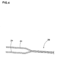
- the aramid fiber tends to be inferior in fatigue resistance owing to high elasticity. Therefore, in this embodiment, to the carcass cords 20 is applied a two bundle twist structure wherein, as shown in Fig. 4 , two bundles 21 (strands 21) of first-twisted filaments of aramid fiber are twisted together. Furthermore, the twisting of two bundles (final twist) is carried out at a higher twist factor T than that conventionally employed.
- a twist factor T as high as 0.5 to 0.7 is adopted, whereby the fatigue resistance that is a drawback of the aramid fiber can be improved and, therefore, the runflat durability can be greatly improved as compared with conventional rayon cords. If the twist factor T of the carcass cord 20 is less than 0.5, the effect of improving the fatigue resistance is small, so the runflat durability cannot be sufficiently improved. If the twist factor T is more than 0.7, the twist processing becomes difficult, so it is industrially disadvantageous. It is preferable that the twist factor T is 0.6 or more, since the fatigue resistance of cords can be further improved to improve the runflat durability.
- a two bundle twist structure is applied to the carcass cords 20 in order to exhibit an excellent reinforcing effect by utilizing a high elasticity which is an important property of the aramid fiber.
- the number of first twists and the number of final twists may be different so long as the ratio of the number of first twists to the number of final twists (number of first twists/number of final twists) falls within the range of 0.2 to 2.0, preferably 0.5 to 1.5.
- the above-mentioned total dtex D (fineness) of a single cord is not particularly limited, but is preferably from 1,500 to 5,000 dtex for runflat tires. Further, it is preferable that a product of the number of cord ends "n" (cords/5 cm) and the total dtex D is from 70,000 to 150,000. If the product is less than 70,000, the runflat durability and the steering stability come short, though aramid fiber is used, and if it is more than 150,000, the rigidity of carcass becomes too large, so the ride comfort is impaired and the weight and cost unnecessarily increase. From such points of view, the product D x n is more preferably at least 100,000 and is at most 120,000.
- Damages of the carcass cords 20 arising from fatigue resistance are easy to occur at portions which receive a compressive strain when a tire is deformed, that is to say, at a bead side portion 6b1 of the ply turnup portion 6b as shown in Fig. 2 .
- the rim-protecting rib 12 is convexly disposed in the bead portion 4 and, therefore, bead deformation in runflat running is decreased and the compressive strain is hard to act on the carcass cords 20.
- fatigue damage of the carcass cords made of aramid fiber can be further suppressed, whereby the runflat durability can be further improved.
- a topping rubber of the carcass ply 6A is used a rubber having a high elasticity as compared with a conventional carcass topping rubber, i.e., a rubber having a complex modulus E* of 5 to 13 MPa.
- the complex modulus E* of a conventional topping rubber for carcass is about 3.8 MPa.
- the complex modulus E* of the carcass topping rubber is less than 5 MPa, the above effect is not expected, and if the complex modulus E* is more than 13 MPa, the rubber becomes too hard, so the ride comfort is remarkably deteriorated. Therefore, it is preferable that the complex modulus E* is 5.5 MPa or more, especially 6 MPa or more, and it is 11 MPa or less, especially 9 MPa or less.
- the profile of outer surface 2A of the tire is formed of a plurality of circular arcs having different radii of curvature.
- the profile is formed of a plurality of such circular arcs that the radius R of curvature gradually decreases from a tire equator point CP which is a point of intersection of the tire outer surface 2A with the tire equator plane C, toward a ground contact edge Te side, whereby the rubber volume of the side-reinforcing rubber layer 11 can be minimized to enhance weight reduction and ride comfort.
- these effects can be more highly exhibited when a special profile as proposed in Japanese Patent No. 2994989 is adopted.
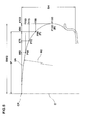
- the radius RC of curvature of the tire outer surface 2A is set to gradually decrease from the tire equator point CP to the point P.
- maximum section width SW of the tire denotes the maximum width on a base profile line "j" of the tire outer surface 2A
- the base profile line "j" denotes a smooth profile line of the outer surface 2A of a tire from which local concave and convex parts such as fine ribs and grooves showing letters, figures and marks for decoration or information, a rim-protecting rib 12 for preventing a rim from coming off and a side-protecting rib for protecting from a cut.
- P60, P75, P90 and P100 denote points on the tire outer surface 2A apart from the tire equator plane C by distances X60, X75, X90 and X100 of 60%, 75%, 90% and 100% of the half width (SW/2) of the tire maximum section width SW, respectively
- Y60, Y75, Y90 and Y100 denote radial distances between the tire equator point CP and each of the points P60, P75, P90 and P100 on the tire outer surface 2A
- SH denotes a section height of the tire in the normal inner pressure condition which is a radial height from a bead base line BL to the tire equator point CP
- the radial distances Y60, Y75, Y90 and Y100 satisfy the following equations.
- RYi Y60/SH
- RY75 Y75/SH
- RY90 Y90/SH
- RY100 Y100/SH. It is reported in Japanese Patent No. 2994989 that since a tread having a profile satisfying the above equations is very round as shown in Figs. 5 and 6 , the footprint of the tire is in a longitudinally long elliptic shape that the ground contact width is small and the ground contact length is large, and the noise performance and aquaplaning performance can be improved.
- the tread portion 2 becomes flat and the profile of the tire outer surface 2A approaches a profile of a conventional tire. If they are more than the above ranges, the tread portion 2 has a markedly convex profile and the ground contact width becomes too small, so necessary running performances in normal running operation cannot be secured.
- the tire outer surface 2A can be suitably determined by depicting it in a smooth curve from the tire equator point CP to the points P mentioned above so as to satisfy the ranges of RY60, RY75, RY90 and RY100 at respective positions and so as to gradually decrease the radius RC of curvature.
- the above-mentioned tire has a ground contact width CW, which is an axial distance between axially outermost edges of a footprint formed when a tire contacts a ground, within the range of 50 to 65 % of the tire maximum section width SW under condition that a load of 80 % of a normal load is applied to the tire under a normal inner pressure condition.
- the reason is that if the ground contact width CW is less than 50 % of the maximum section width SW, the wandering performance is deteriorated under normal running condition and uneven wear is easy to occur due to uneven ground contact pressure. If the ground contact width CW is more than 65 % of the maximum section width SW, the ground contact width is excessively large and it is difficult to simultaneously achieve both of good passing noise performance and good aquaplaning performance.
- the pneumatic tire 1 of the present invention can be formed into normal tire 1B for passenger cars, as shown in Fig. 7 .
- the passenger car tire 1B can have approximately the same structure as the above-mentioned runflat tire 1A except that the side-reinforcing rubber layer 11 is not disposed.
- the rigidity of carcass is enhanced by the use of the carcass cords 20 of aramid fiber, so the steering stability in normal running can be enhanced to achieve high speed running and high performances with achievement of weight reduction.
- the above-mentioned high elastic rubber having a complex modulus of 5 to 13 MPa is used as a topping rubber for the carcass ply 6A, a strain occurring in the carcass cords 20 can be reduced as well as further enhancing the steering stability in normal running, so a fatigue damage of the aramid fiber cords can be suppressed to enhance the durability.
- the total nominal dtex D of the carcass cords 20 in the passenger car tire 1B is from 1,000 to 5,000 dtex, and the product of the total nominal dtex D and the number of cord ends "n" (per 5 cm) is from 80,000 to 120,000.
- the pneumatic tire 1 of the present invention can be formed into normal tire 1C for motorcycles, as shown in Fig. 8 .
- the rigidity of carcass is enhanced by the use of the carcass cords 20 of aramid fiber, so the steering stability in normal running can be enhanced to achieve high speed running and high performances with achievement of weight reduction.
- the above-mentioned high elastic rubber having a complex modulus of 5 to 13 MPa is used as a topping rubber for the carcass ply 6A, a strain occurring in the carcass cords 20 can be reduced as well as further enhancing the steering stability in normal running, so a fatigue damage of the aramid fiber cords can be suppressed to enhance the durability.
- the total nominal dtex D of the carcass cords 20 in the motorcycle tire 1C is from 1,000 to 2,500 dtex, and the product of the total nominal dtex D and the number of cord ends "n" (per 5 cm) is from 80,000 to 120,000.
- the profile of the outer surface 2A of the motorcycle tire 1C is such that the radius RCe of curvature on a ground contact edge Te side is larger than the radius RCo of curvature at the tire equator point CP, whereby the stability in cornering is secured with exhibiting the cornering performance peculiar to motorcycles when banking a motorcycle body.
- Runflat tires of size 245/40R18 having the structure shown in Fig. 1 were manufactured based on the specifications shown in Table 1, and tested with respect to the runflat durability. The results are shown in Table 1. Specifications other than the carcass cords shown in Table 1 are common to all tires. Carcass: single ply, cord angle 90° Belt layer: two plies, cord angles +24°/-24° Side-reinforcing rubber layer: hardness 90, maximum thickness 10.0 mm
- twist factor T N ⁇ 0.125 ⁇ D / 2 / ⁇ ⁇ 10 - 3
- specific gravity of the rayon fiber cord 1.51
- specific gravity of the aramid fiber cord 1.44.
- a tire was mounted on a rim (18 ⁇ 8.5J) from which a valve core was removed, and it was run on a drum tester in the deflated state at a speed of 80 km/hour under a vertical load of 4.14 kN. The running distance up to breaking of the tire was measured. The results are shown as an index based on the result of Comparative Example 1 regarded as 100. The larger the value, the better the durability.
- the fatigue resistance which is drawback of the aramid fiber cords can be improved by increasing the twist factor T to 0.5 or more and, therefore, an excellent heat resistance and an excellent load-supporting ability which are advantages of the aramid fiber cords can be effectively exhibited to improve the runflat durability.
- the twist factor T increases, the fatigue resistance is increased to improve the runflat durability.
- the runflat durability is improved by increasing the complex modulus of the topping rubber to 5 MPa or more.
Landscapes
- Engineering & Computer Science (AREA)
- Mechanical Engineering (AREA)
- Textile Engineering (AREA)
- Tires In General (AREA)
- Yarns And Mechanical Finishing Of Yarns Or Ropes (AREA)
Abstract

in which N is the number of final twists per 10 cm, D is a total nominal dtex (fineness) of a cord, and

Description
- The present invention relates to a pneumatic tire which is suitable as, for example, a passenger car tire and a motorcycle tire, particularly as a runflat tire, and which has various tire performances improved with achieving weight reduction.
- As a runflat tire capable of traveling for a relatively long distance in a deflated condition that the tire loses air pressure due to a puncture, there is known, for example, a tire of so-called side-reinforced type wherein a side-reinforcing rubber layer having a crescent-shaped cross section is disposed in each sidewall portion (see for example Patent Literature 1). In the runflat tire of this type, a plurality of carcass plies are used in order to enhance a load-supporting ability. Further, a rayon fiber cord which has a good heat resistance is used as a carcass cord in order to secure a durability in runflat mode, since the tire temperature in runflat mode is very high as compared with that during normal running in the inflated state.
- Patent Literature 1:
JP 2000-351307 A - Tires having the above-mentioned structure have a necessary minimum durability, but further improvement in runflat durability and steering stability is strongly desired from the viewpoints of recent demands for high running speed and long running distance in runflat mode.
- Accordingly, it is an object of the present invention to provide a pneumatic tire which can enhance the steering stability and durability in runflat running, with achieving weight reduction, to achieve a high running speed and a long running distance in runflat running when used as a runflat tire, and which can achieve, in normal running, enhancement of the steering stability, a high running speed and a long running distance with achieving weight reduction when used as a tire for passenger car or motorcycle. The present invention is based on using, as a carcass cord, an aramid fiber cord which has a heat resistance superior to that of a rayon fiber cord and a high elasticity.
- In order to achieve the object mentioned above, the invention as claimed in
claim 1 of the present application is directed to a pneumatic tire including a carcass extending from a tread portion to bead cores in bead portions through sidewall portions, and a tread-reinforcing cord layer disposed radially outward of the carcass and in the tread portion, and is characterized in that in the meridian cross section including the rotational axis of the tire in a normal inner pressure condition that the tire is mounted on a normal rim and inflated to a normal inner pressure,
the outer surface of the tire has a curved profile composed of a plurality of circular arcs having different radii of curvature,
the carcass comprises a carcass ply in which carcass cords are arranged at an angle of 45 to 90° with respect to a circumferential direction of the tire and are covered with a topping rubber, and
an aramid fiber is used for the carcass cords. - The invention as claimed in
claim 2 is characterized in that the carcass cords have a two-bundle twisted structure that two bundles of first-twisted filaments are subjected to final twist. - The invention as claimed in
claim 3 is characterized in that the carcass cords have a twist factor T of 0.5 to 0.7 represented by the equation (1):
in which N is the number of final twists per 10 cm, D is a total nominal dtex of a cord, andis a specific gravity of a cord material.
- The invention as claimed in
claim 4 is characterized in that the twist factor T of the carcass cords is from 0.6 to 0.7. - The invention as claimed in
claim 5 is characterized in that the topping rubber of the carcass ply has a complex modulus E* of 5 to 13 MPa. - The invention as claimed in
claim 6 is characterized in that the pneumatic tire is a runflat tire provided in the sidewall portions with side-reinforcing rubber layers each having a cross section of such a crescent-shape that it has the maximum thickness at a center portion thereof and extends radially inward and outward from the center portion with decreasing its thickness. - The invention as claimed in
claim 7 is characterized in that the outer surface of the tire has a curved profile composed of a plurality of circular arcs having radii of curvature which gradually decrease from a tire equator point CP at which the outer surface of the tire intersects with a tire equator plane C toward a ground contact edge side. - The invention as claimed in
claim 8 is characterized in that the outer surface of the tire has a profile such that the radius of curvature of the outer surface of the tire gradually decreases from the tire equator point CP to a point P, in which the point P denotes a point on the tire outer surface which is apart from the tire equator plane C by a distance SP of 45 % of the maximum section width SW of the tire, and the profile satisfies the following equations:


in which Y60, Y75, Y90 and Y100 denote radial distances between the tire equator point CP and each of points on the tire outer surface apart from the tire equator plane C by distances X60, X75, X90 and X100 of 60%, 75%, 90% and 100% of the half width (SW/2) of the tire maximum section width SW, respectively, and SH denotes a section height of the tire. - The invention as claimed in
claim 9 is characterized in that the outer surface of the tire has a profile such that the radius of curvature measured on a ground contact edge side is larger than that measured at the tire equator point CP at which the outer surface of the tire intersects with the tire equator plane C. - The term "normal rim" as used herein means a rim defined for every tire in a standardizing system on which the tire is based and, for example, denotes "standard rim" in JATMA, "design rim" in TRA and "measuring rim" in ETRTO. Also, the term "normal inner pressure" as used herein means an air pressure defined for every tire in a standardizing system and, for example, denotes the maximum air pressure in JATMA, the maximum value recited in the table of "Tire Load Limits at Various Cold Inflation Pressures" in TRA, and the "Inflation Pressure" in ETRTO, provided that in case of tires for passenger cars, the "normal inner pressure" is 180 kPa.
- Further, the term "complex modulus" (E*) as used herein denotes a value measured with a viscoelasticity spectrometer under the conditions of measuring
temperature 70°C, initial tension 1,000 g, dynamic strain ±0.03%, andfrequency 10 Hz. - In the present invention, as mentioned above, an aramid fiber cord superior particularly in heat resistance is used as a carcass cord. Therefore, damages of the cord owing to temperature elevation during ranflat running can be suppressed. Further, since the aramid fiber cord has a high elasticity and accordingly can enhance the load-supporting ability, deformation of the tire in runflat running can be reduced while achieving decrease in the number of plies (weight reduction). Accordingly, in cooperation with the enhancement of heat resistance, the runflat durability can be enhanced. Further, the steering stability in runflat mode can be improved, thus achieving high running speed and long running distance in runflat mode.
- Further, in case of the tires for passenger cars and the tires for motorcycles, the steering stability can be improved to achieve high running speed and high performances in normal running, with achieving weight reduction.
-
-
Fig. 1 is a meridian cross sectional view illustrating an embodiment of the present invention wherein the pneumatic tire is a runflat tire; -
Fig. 2 is a cross sectional view illustrating a tread portion in an enlarged form of the tire shown inFig. 1 ; -
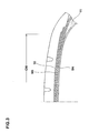
Fig. 3 is a cross sectional view illustrating a bead portion in an enlarged form of the tire shown inFig. 1 ; -
Fig. 4 is side view illustrating a carcass cord; -
Fig. 5 is a diagram showing a profile of the outer surface of a tire; -
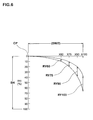
Fig. 6 is a diagram showing a range of RYi at each location on the outer surface of the tire; -
Fig. 7 is a meridian cross sectional view illustrating an embodiment of the present invention wherein the pneumatic tire is a passenger car tire; and -
Fig. 8 is a meridian cross sectional view illustrating an embodiment of the present invention wherein the pneumatic tire is a motorcycle tire. -
- 2.
- Tread portion
- 3.
- Sidewall portion
- 4.
- Bead portion
- 5.
- Bead core
- 6.
- Carcass
- 6A
- Carcass ply
- 7.
- Tread-reinforcing cord layer
- 11.
- Side-reinforcing rubber layer
- 20.
- Carcass cord
- 21.
- Bundle of filaments
- An embodiment of the present invention will now be explained with reference to the accompanying drawings.
Fig. 1 is a meridian cross section view of a tire in the normal inner pressure condition wherein atire 1 according to the present invention is arunflat tire 1A. - In
Fig. 1 , therunflat tire 1A in this embodiment includes acarcass 6 that extends from atread portion 2 to beadcores 5 inbead portions 4 throughsidewall portions 3, and a tread-reinforcingcord layer 7 that is disposed radially outward of thecarcass 6 in thetread portion 2. - The
carcass 6 comprises at least one carcass ply in which carcass cords are disposed at an angle of 45 to 90° with respect to the tire circumferential direction and covered with a topping rubber. In this embodiment is shown a carcass composed of asingle carcass ply 6A of carcass cords arranged at an angle of 80 to 90°. Thecarcass ply 6A is composed of aply body portion 6a that extends between thebead cores turnup portions 6b that are continuous with theply body portion 6a and are turned up around thebead cores 5 from the axially inside to the axially outside of the tire. - A
bead apex rubber 8 for reinforcing the bead portion, which is for example made of a hard rubber having a rubber hardness of 65 to 98, is disposed between theply body portion 6a and theply turnup portion 6b to radially outwardly extend from thebead core 5 in a tapered manner. The "rubber hardness" as used herein denotes a hardness measured by a durometer type A at 23°C. Radial height "ha" of thebead apex rubber 8 from a bead base line BL is not particularly limited. However, if the height of thebead apex rubber 8 is too small, the runflat durability may be deteriorated, and if the height is too large, the tire weight may excessively increase or the ride comfort may be deteriorated. Therefore, it is preferred that the height "ha" of thebead apex rubber 8 is from 10 to 60 %, especially 20 to 50 %, of the section height SH of the tire. - In this embodiment, the
carcass ply 6A has a so-called high turnup structure wherein theply turnup portion 6b of thecarcass 6 extends radially outwardly beyond the radially outer end of thebead apex rubber 8 and terminates so that outer end 6be of theturnup portion 6b is sandwiched between theply body portion 6a and the tread-reinforcingcord layer 7. This structure can effectively reinforce thesidewall portion 3 by the use ofsingle carcass ply 6A. Also, since the outer end 6be of theply turnup portion 6b is located apart from thesidewall portion 3 that is greatly bent during runflat running, damages occurring from the outer end 6be can be suitably suppressed. The axial width EW of the overlapping part of theturnup portion 6b with the tread-reinforcingcord layer 7 is preferably at least 5 mm, more preferably at least 10 mm. It is also preferably at most 40 mm, more preferably at most 30 mm, from the viewpoint of weight reduction. In case of forming thecarcass 6 using a plurality of carcass plies, it is preferable that at least one carcass ply has such a high turnup structure. - The tread-reinforcing
cord layer 7 in this embodiment comprises abelt 9 superposed on thecarcass 6, and aband 10 superposed outward of thebelt 9. Thebelt 9 comprises at least two belt plies (in this embodiment, two belt plies 9A and 9B) in each of which belt cords are arranged at an angle, for example, of 10 to 45° with respect to the tire circumferential direction and covered with a topping rubber. The belt plies are stacked so that the belt cords in one ply crosses the cords in the other belt ply, whereby the rigidity of the belt is enhanced to strongly reinforce thetread portion 2 over approximately full width thereof by a hoop effect. - The
band 10 comprises at least one band ply in which a band cord is spirally wound at an angle of 5° or less with respect to the tire circumferential direction and covered with a topping rubber. The band serves to bind thebelt 9, thereby enhancing the steering stability, high speed durability and the like. As the band ply are adoptable a pair of right and left edge band plies which are disposed to cover only axially outer edge portions of thebelt 9, a full band ply which covers approximately full width of thebelt 9, and a combination of them. Theband 10 shown in this embodiment comprises a single full band ply. The tread-reinforcingcord layer 7 may be formed ofonly belt 9 oronly band 10. - In order to secure the runflat performances, side-reinforcing
rubber layers 11 are disposed in thesidewall portions 3. The side-reinforcingrubber layer 11 has a cross section of such a crescent-shape that it has the maximum thickness at itscenter portion 11a and extends radially from thecenter portion 11 a toward both a radiallyinner end 11i and a radially outer end 11o with gradually decreasing the thickness, respectively. Theinner end 11i is located radially inward of the radially outer end of thebead apex rubber 8, and the outer end 11o is located axially inward of anouter end 7e of the tread-reinforcingcord layer 7. It is preferable that the radial width Wi of an overlapping part of the side-reinforcingrubber layer 11 with thebead apex rubber 8 is from 5 to 50 mm, and the axial width Wo of an overlapping part of the side-reinforcingrubber layer 11 with the tread-reinforcingcord layer 7 is from 0 to 50 mm, whereby occurrence of a difference in rigidity at the outer and inner ends 11o and 11i of the reinforcingrubber layer 11 is controlled. - In this embodiment, the side-reinforcing
rubber layer 11 is disposed axially inward (on a tire cavity side) of theply body portion 6a of thecarcass 6 and, therefore, when thesidewall portion 3 is subject to a flexural deformation, mainly a compressive load acts on the side-reinforcingrubber layer 11 and a tensile load acts on thecarcass ply 6A which includes a cord material. Since a rubber material is resistant to the compressive load and a cord material is resistant to the tensile load, the configuration as mentioned above of the side-reinforcingrubber layer 11 can efficiently enhance the flexural rigidity of thesidewall portion 3, thus effectively decreasing a vertical flex of a tire in runflat mode. It is preferable that the side-reinforcingrubber layer 11 has a rubber hardness of at least 60, especially at least 65. If the hardness is less than 60, the compressive strain in runflat mode is large, so sufficient runflat performances are not obtained. If the hardness is too high, the longitudinal spring constant of a tire excessively increases to lower the ride comfort. From such points of view, it is preferable that the hardness of the side-reinforcingrubber layer 11 is at most 90, especially at most 80. The maximum thickness "t" of the side-reinforcingrubber layer 11 is suitably selected depending on tire size, kind of the tire and the like. In case of tires for passenger cars, the maximum thickness "t" is usually from 5 to 20 mm. - In this embodiment, a rim-protecting
rib 12 is convexly disposed in thebead portion 4. The rim-protectingrib 12 is, as shown inFig. 2 , a rib projecting from a base profile line "j" to cover a rim flange JF. It has a trapezoidal cross section which is enclosed by a projectingface 12c which projects most axially outwardly, a radiallyinner slope 12i which smoothly continues from the projectingface 12c to the axially outer surface of the bead portion, and a radially outer slope 12o which smoothly continues from the projectingface 12c to the base profile line "j" in the vicinity of a tire maximum width point M. The radiallyinner slope 12i is a concave arc-like face having a larger radius "r" of curvature than an arc-like portion of the rim flange JF, and serves to protect the rim flange JF from stones in normal running condition. It also serves to decrease the amount of deformation of the bead portion in runflat running condition, thus improving the steering stability in runflat running and the runflat durability, since the radiallyinner slope 12i will contact the rim flange JF with leaning against the arc-like portion of the rim flange JF. - In the present invention, an aramid fiber is used in the carcass cords in order to improve the runflat steering stability and the runflat durability.
- The aramid fiber is known as a high elastic fiber, and can enhance the load-supporting ability of
runflat tire 1A by using it in carcass cords of therunflat tire 1A. Therefore, it is possible to reduce deformation of the tire in runflat mode while achieving weight reduction based on, for example, decrease in number of carcass plies, diameter of carcass cords, and/or cord arrangement density (number of cord ends). Furthermore, decrease in elastic modulus of the aramid fiber is small even at a high temperature of 100 to 150°C as compared with other organic fiber cord materials and, therefore, the aramid fiber has an excellent heat resistance. Therefore, even if the tire temperature elevates during runflat running, it is possible to prevent occurrence of damage owing to lowering of strength of the carcass cords, increase in tire deformation amount owing to lowering of elastic modulus, and accompanying further elevation of tire temperature. Thus, the runflat durability can be improved. Further, it is possible to improve the steering stability in runflat mode, since the high elastic modulus can be maintained to enhance the tire rigidity even if the tire temperature elevates. Thus, high running speed and long running distance in runflat mode can be achieved. - However, the aramid fiber tends to be inferior in fatigue resistance owing to high elasticity. Therefore, in this embodiment, to the
carcass cords 20 is applied a two bundle twist structure wherein, as shown inFig. 4 , two bundles 21 (strands 21) of first-twisted filaments of aramid fiber are twisted together. Furthermore, the twisting of two bundles (final twist) is carried out at a higher twist factor T than that conventionally employed. - The "twist factor T" is represented, as well known, by the following equation (1):

in which N is the number of final twists of cord per 10 cm, D is a total nominal dtex of single cord (fineness), andis a specific gravity of a cord material.
- A twist factor T as high as 0.5 to 0.7 is adopted, whereby the fatigue resistance that is a drawback of the aramid fiber can be improved and, therefore, the runflat durability can be greatly improved as compared with conventional rayon cords. If the twist factor T of the
carcass cord 20 is less than 0.5, the effect of improving the fatigue resistance is small, so the runflat durability cannot be sufficiently improved. If the twist factor T is more than 0.7, the twist processing becomes difficult, so it is industrially disadvantageous. It is preferable that the twist factor T is 0.6 or more, since the fatigue resistance of cords can be further improved to improve the runflat durability. - A two bundle twist structure is applied to the
carcass cords 20 in order to exhibit an excellent reinforcing effect by utilizing a high elasticity which is an important property of the aramid fiber. In this case, there is preferred a so-called balanced twisting that the number of first twists is the same as the number of the final twists. However, the number of first twists and the number of final twists may be different so long as the ratio of the number of first twists to the number of final twists (number of first twists/number of final twists) falls within the range of 0.2 to 2.0, preferably 0.5 to 1.5. - The above-mentioned total dtex D (fineness) of a single cord is not particularly limited, but is preferably from 1,500 to 5,000 dtex for runflat tires. Further, it is preferable that a product of the number of cord ends "n" (cords/5 cm) and the total dtex D is from 70,000 to 150,000. If the product is less than 70,000, the runflat durability and the steering stability come short, though aramid fiber is used, and if it is more than 150,000, the rigidity of carcass becomes too large, so the ride comfort is impaired and the weight and cost unnecessarily increase. From such points of view, the product D x n is more preferably at least 100,000 and is at most 120,000.
- Damages of the
carcass cords 20 arising from fatigue resistance are easy to occur at portions which receive a compressive strain when a tire is deformed, that is to say, at a bead side portion 6b1 of theply turnup portion 6b as shown inFig. 2 . However, in this embodiment, the rim-protectingrib 12 is convexly disposed in thebead portion 4 and, therefore, bead deformation in runflat running is decreased and the compressive strain is hard to act on thecarcass cords 20. As a result, fatigue damage of the carcass cords made of aramid fiber can be further suppressed, whereby the runflat durability can be further improved. In other words, in tires using carcass cords made of aramid fiber, it is preferable to use the rim-protectingrib 12 from the viewpoint of suppressing the fatigue damage of the cords. - Further, in this embodiment, as a topping rubber of the
carcass ply 6A is used a rubber having a high elasticity as compared with a conventional carcass topping rubber, i.e., a rubber having a complex modulus E* of 5 to 13 MPa. The complex modulus E* of a conventional topping rubber for carcass is about 3.8 MPa. By using such a high elastic rubber as a topping rubber, a strain generating at thecarcass cords 20 when a tire is deformed can be decreased, thus further improvement of the runflat durability can be achieved. If the complex modulus E* of the carcass topping rubber is less than 5 MPa, the above effect is not expected, and if the complex modulus E* is more than 13 MPa, the rubber becomes too hard, so the ride comfort is remarkably deteriorated. Therefore, it is preferable that the complex modulus E* is 5.5 MPa or more, especially 6 MPa or more, and it is 11 MPa or less, especially 9 MPa or less. - In the meridian cross section of the tire in the above-mentioned normal inner pressure condition, the profile of
outer surface 2A of the tire is formed of a plurality of circular arcs having different radii of curvature. In particular, in case of therunflat tire 1A, it is preferable that the profile is formed of a plurality of such circular arcs that the radius R of curvature gradually decreases from a tire equator point CP which is a point of intersection of the tireouter surface 2A with the tire equator plane C, toward a ground contact edge Te side, whereby the rubber volume of the side-reinforcingrubber layer 11 can be minimized to enhance weight reduction and ride comfort. In particular, these effects can be more highly exhibited when a special profile as proposed in Japanese Patent No.2994989 - To explain in more detail, as shown in
Fig. 5 , if "P" is defined as a point on the tireouter surface 2A which is apart from the tire equator plane C by a distance SP of 45 % of a maximum section width SW of the tire, the radius RC of curvature of the tireouter surface 2A is set to gradually decrease from the tire equator point CP to the point P. The above-mentioned "maximum section width SW" of the tire denotes the maximum width on a base profile line "j" of the tireouter surface 2A, and the base profile line "j" denotes a smooth profile line of theouter surface 2A of a tire from which local concave and convex parts such as fine ribs and grooves showing letters, figures and marks for decoration or information, a rim-protectingrib 12 for preventing a rim from coming off and a side-protecting rib for protecting from a cut. - Further, if P60, P75, P90 and P100 denote points on the tire
outer surface 2A apart from the tire equator plane C by distances X60, X75, X90 and X100 of 60%, 75%, 90% and 100% of the half width (SW/2) of the tire maximum section width SW, respectively, and if Y60, Y75, Y90 and Y100 denote radial distances between the tire equator point CP and each of the points P60, P75, P90 and P100 on the tireouter surface 2A, and if SH denotes a section height of the tire in the normal inner pressure condition which is a radial height from a bead base line BL to the tire equator point CP, the radial distances Y60, Y75, Y90 and Y100 satisfy the following equations.


- Ranges RYi satisfying the above equations are shown in
Fig. 6 wherein RY60 = Y60/SH, RY75 = Y75/SH, RY90 = Y90/SH and RY100 = Y100/SH. It is reported in Japanese Patent No.2994989 Figs. 5 and6 , the footprint of the tire is in a longitudinally long elliptic shape that the ground contact width is small and the ground contact length is large, and the noise performance and aquaplaning performance can be improved. If the values of RY60, RY75, RY90 and RY100 are less than the above ranges, thetread portion 2 becomes flat and the profile of the tireouter surface 2A approaches a profile of a conventional tire. If they are more than the above ranges, thetread portion 2 has a markedly convex profile and the ground contact width becomes too small, so necessary running performances in normal running operation cannot be secured. - Since the aspect ratio of tire, the maximum section width of tire, the maximum height of tire and the like can be approximately determined from tire standards such as JATMA and ETRTO if the tire size is previously determined, the ranges of RY60, RY75, RY90 and RY100 can be readily calculated. Therefore, the tire
outer surface 2A can be suitably determined by depicting it in a smooth curve from the tire equator point CP to the points P mentioned above so as to satisfy the ranges of RY60, RY75, RY90 and RY100 at respective positions and so as to gradually decrease the radius RC of curvature. - It is preferable that the above-mentioned tire has a ground contact width CW, which is an axial distance between axially outermost edges of a footprint formed when a tire contacts a ground, within the range of 50 to 65 % of the tire maximum section width SW under condition that a load of 80 % of a normal load is applied to the tire under a normal inner pressure condition. The reason is that if the ground contact width CW is less than 50 % of the maximum section width SW, the wandering performance is deteriorated under normal running condition and uneven wear is easy to occur due to uneven ground contact pressure. If the ground contact width CW is more than 65 % of the maximum section width SW, the ground contact width is excessively large and it is difficult to simultaneously achieve both of good passing noise performance and good aquaplaning performance.
- Since such a special profile has the feature that the region of the sidewall portion is short, the volume of a rubber required for the side-reinforcing
rubber layer 11 can be decreased by adopting it to runflat tires and, therefore, weight reduction and improvement in ride comfort of runflat tires can be achieved. On the other hand, the amount of deformation intread portion 2 having a large rubber volume becomes larger as compared with tires having a usual tread profile. Therefore, the carcass cords of aramid fiber having an enhanced heat resistance are also advantageous for tires having this special profile. - The
pneumatic tire 1 of the present invention can be formed intonormal tire 1B for passenger cars, as shown inFig. 7 . In this case, thepassenger car tire 1B can have approximately the same structure as the above-mentionedrunflat tire 1A except that the side-reinforcingrubber layer 11 is not disposed. In thepassenger car tire 1B, the rigidity of carcass is enhanced by the use of thecarcass cords 20 of aramid fiber, so the steering stability in normal running can be enhanced to achieve high speed running and high performances with achievement of weight reduction. In the case that the above-mentioned high elastic rubber having a complex modulus of 5 to 13 MPa is used as a topping rubber for thecarcass ply 6A, a strain occurring in thecarcass cords 20 can be reduced as well as further enhancing the steering stability in normal running, so a fatigue damage of the aramid fiber cords can be suppressed to enhance the durability. It is preferable that the total nominal dtex D of thecarcass cords 20 in thepassenger car tire 1B is from 1,000 to 5,000 dtex, and the product of the total nominal dtex D and the number of cord ends "n" (per 5 cm) is from 80,000 to 120,000. - Further, the
pneumatic tire 1 of the present invention can be formed intonormal tire 1C for motorcycles, as shown inFig. 8 . In themotorcycle tire 1C, too, the rigidity of carcass is enhanced by the use of thecarcass cords 20 of aramid fiber, so the steering stability in normal running can be enhanced to achieve high speed running and high performances with achievement of weight reduction. Further, in the case that the above-mentioned high elastic rubber having a complex modulus of 5 to 13 MPa is used as a topping rubber for thecarcass ply 6A, a strain occurring in thecarcass cords 20 can be reduced as well as further enhancing the steering stability in normal running, so a fatigue damage of the aramid fiber cords can be suppressed to enhance the durability. It is preferable that the total nominal dtex D of thecarcass cords 20 in themotorcycle tire 1C is from 1,000 to 2,500 dtex, and the product of the total nominal dtex D and the number of cord ends "n" (per 5 cm) is from 80,000 to 120,000. - The profile of the
outer surface 2A of themotorcycle tire 1C is such that the radius RCe of curvature on a ground contact edge Te side is larger than the radius RCo of curvature at the tire equator point CP, whereby the stability in cornering is secured with exhibiting the cornering performance peculiar to motorcycles when banking a motorcycle body. - While particularly preferable embodiments of the present invention have been described, the present invention can be practiced with various changes and modifications without being limited to the embodiments shown in the drawings.
- Runflat tires of size 245/40R18 having the structure shown in
Fig. 1 were manufactured based on the specifications shown in Table 1, and tested with respect to the runflat durability. The results are shown in Table 1. Specifications other than the carcass cords shown in Table 1 are common to all tires.
Carcass: single ply,cord angle 90°
Belt layer: two plies, cord angles +24°/-24°
Side-reinforcing rubber layer:hardness 90,
maximum thickness 10.0 mm - In Table 1, the twist factor T is represented by the following equation (1):

Further, the specific gravityof the rayon fiber cord is 1.51, and the specific gravity of the aramid fiber cord is 1.44.
- All tires have substantially the same tread profile within the ranges of RY60 = 0.05 to 0.1, RY75 = 0.1 to 0.2, RY90 = 0.2 to 0.4 and RY100 = 0.4 to 0.7.
- A tire was mounted on a rim (18×8.5J) from which a valve core was removed, and it was run on a drum tester in the deflated state at a speed of 80 km/hour under a vertical load of 4.14 kN. The running distance up to breaking of the tire was measured. The results are shown as an index based on the result of Comparative Example 1 regarded as 100. The larger the value, the better the durability.


- As understood from comparison of Examples 1 and 2 with Examples 3 and 4, the fatigue resistance which is drawback of the aramid fiber cords can be improved by increasing the twist factor T to 0.5 or more and, therefore, an excellent heat resistance and an excellent load-supporting ability which are advantages of the aramid fiber cords can be effectively exhibited to improve the runflat durability. From Examples 5, 7 and 9 or from Examples 6, 8 and 10, it is also understood that as the twist factor T increases, the fatigue resistance is increased to improve the runflat durability. Further, from Examples 3 and 7 or from Examples 4 and 8, it is understood that in case that the twist factor T is the same, the runflat durability is improved by increasing the complex modulus of the topping rubber to 5 MPa or more.
Claims (9)
- A pneumatic tire including a carcass extending from a tread portion to bead cores in bead portions through sidewall portions, and a tread-reinforcing cord layer disposed radially outward of the carcass and in the tread portion, wherein in the meridian cross section including the rotational axis of the tire in a normal inner pressure condition that the tire is mounted on a normal rim and inflated to a normal inner pressure,
the outer surface of the tire has a curved profile composed of a plurality of circular arcs having different radii of curvature,
the carcass comprises a carcass ply in which carcass cords are arranged at an angle of 45 to 90° with respect to a circumferential direction of the tire and are covered with a topping rubber, and
an aramid fiber is used for the carcass cords. - The pneumatic tire of claim 1, wherein the carcass cords have a two-bundle twisted structure that two bundles of first-twisted filaments are subjected to final twist.
- The pneumatic tire of claim 1 or 2, wherein the carcass cords have a twist factor T of 0.5 to 0.7 represented by the equation (1):

in which N is the number of final twists per 10 cm, D is a total nominal dtex (fineness) of a cord, andis a specific gravity of a cord material.
- The pneumatic tire of claim 3, wherein the twist factor T of the carcass cords is from 0.6 to 0.7.
- The pneumatic tire of any one of claims 1 to 4, wherein the topping rubber of the carcass ply has a complex modulus E* of 5 to 13 MPa.
- The pneumatic tire of any one of claims 1 to 5, wherein the pneumatic tire is a runflat tire provided in the sidewall portions with side-reinforcing rubber layers each having a cross section of such a crescent-shape that it has the maximum thickness at a center portion thereof and extends radially inward and outward from the center portion with decreasing its thickness.
- The pneumatic tire of any one of claims 1 to 6, wherein the outer surface of the tire has a curved profile composed of a plurality of circular arcs having radii of curvature which gradually decrease from a tire equator point CP which is a point of intersection of the outer surface of the tire with a tire equator plane C, toward a ground contact edge side.
- The pneumatic tire of claim 7, wherein the outer surface of the tire has a profile such that the radius RC of curvature of the outer surface of the tire gradually decreases from the tire equator point CP to a point P, in which the point P denotes a point on the outer surface which is apart from the tire equator plane C by a distance SP of 45 % of a maximum section width SW of the tire, and the profile satisfies the following equations:


in which Y60, Y75, Y90 and Y100 denote radial distances between the tire equator point CP and each of points on the tire outer surface apart from the tire equator plane C by distances X60, X75, X90 and X100 of 60%, 75%, 90% and 100% of the half width (SW/2) of the tire maximum section width SW, respectively, and SH denotes a section height of the tire. - The pneumatic tire of any one of claims 1 to 5, wherein the outer surface of the tire has a profile such that the radius of curvature measured on a ground contact edge side is larger than that measured at the tire equator point CP.
Applications Claiming Priority (2)
| Application Number | Priority Date | Filing Date | Title |
|---|---|---|---|
| JP2007147190A JP4769228B2 (en) | 2007-06-01 | 2007-06-01 | Run flat tire |
| PCT/JP2008/059714 WO2008149725A1 (en) | 2007-06-01 | 2008-05-27 | Pneumatic tire |
Publications (3)
| Publication Number | Publication Date |
|---|---|
| EP2151332A1 true EP2151332A1 (en) | 2010-02-10 |
| EP2151332A4 EP2151332A4 (en) | 2014-01-08 |
| EP2151332B1 EP2151332B1 (en) | 2016-01-06 |
Family
ID=40093546
Family Applications (1)
| Application Number | Title | Priority Date | Filing Date |
|---|---|---|---|
| EP08764742.6A Not-in-force EP2151332B1 (en) | 2007-06-01 | 2008-05-27 | Pneumatic tire |
Country Status (8)
| Country | Link |
|---|---|
| US (1) | US8622107B2 (en) |
| EP (1) | EP2151332B1 (en) |
| JP (1) | JP4769228B2 (en) |
| KR (1) | KR101477317B1 (en) |
| CN (1) | CN101678716B (en) |
| BR (1) | BRPI0811133A2 (en) |
| RU (1) | RU2467883C2 (en) |
| WO (1) | WO2008149725A1 (en) |
Cited By (3)
| Publication number | Priority date | Publication date | Assignee | Title |
|---|---|---|---|---|
| EP2939854A3 (en) * | 2014-05-02 | 2016-03-09 | Sumitomo Rubber Industries, Ltd. | Pneumatic tire |
| EP3153331B1 (en) * | 2014-06-06 | 2019-08-28 | Bridgestone Corporation | Pneumatic tire |
| EP4253086A4 (en) * | 2022-01-27 | 2024-07-31 | Qingdao Doublestar Tire Industrial Co., Ltd. | SUPPORT RUBBER AND INTERNAL SELF-SUPPORTING TIRE FOR A WHOLE RANGE OF PASSENGER CARS AND MANUFACTURING METHOD FOR AN INTERNAL SELF-SUPPORTING TIRE |
Families Citing this family (28)
| Publication number | Priority date | Publication date | Assignee | Title |
|---|---|---|---|---|
| JP4635041B2 (en) * | 2007-12-06 | 2011-02-16 | 住友ゴム工業株式会社 | Run flat tire |
| WO2009072420A1 (en) * | 2007-12-06 | 2009-06-11 | Sumitomo Rubber Industries, Ltd. | Run-flat tire |
| JP4635040B2 (en) * | 2007-12-06 | 2011-02-16 | 住友ゴム工業株式会社 | Run flat tire |
| JP5611776B2 (en) * | 2010-11-08 | 2014-10-22 | 東洋ゴム工業株式会社 | Elastic joint |
| US20150298510A1 (en) * | 2012-11-30 | 2015-10-22 | The Yokohama Rubber Co., Ltd. | Pneumatic Tire |
| FR3006628B1 (en) * | 2013-06-10 | 2015-05-29 | Michelin & Cie | CARCASS AND PNEUMATIC TOP FOR MOTORCYCLE FRAME |
| JP6301105B2 (en) * | 2013-10-28 | 2018-03-28 | 株式会社ブリヂストン | Run-flat radial tire |
| JP6249518B2 (en) * | 2013-11-18 | 2017-12-20 | 住友ゴム工業株式会社 | Pneumatic tire |
| JP6278508B2 (en) * | 2013-11-18 | 2018-02-14 | 住友ゴム工業株式会社 | Motorcycle tire for rough terrain |
| JP6346492B2 (en) * | 2014-05-12 | 2018-06-20 | 住友ゴム工業株式会社 | Pneumatic tire |
| JP2018505096A (en) | 2015-02-11 | 2018-02-22 | ブリヂストン アメリカズ タイヤ オペレーションズ、 エルエルシー | Run flat tire with sidewall reinforcement insert |
| TR201801495T1 (en) * | 2015-09-17 | 2018-06-21 | Kordsa Teknik Tekstil As | ON A GENERATION STRENGTHENING CORD |
| WO2017072708A1 (en) * | 2015-10-30 | 2017-05-04 | Pirelli Tyre S.P.A. | Tyre for bicycle wheels |
| JP6529002B1 (en) * | 2017-09-12 | 2019-06-12 | 住友ゴム工業株式会社 | Pneumatic tire |
| JP7102770B2 (en) * | 2018-02-22 | 2022-07-20 | 住友ゴム工業株式会社 | Pneumatic tires |
| JP7124494B2 (en) * | 2018-07-03 | 2022-08-24 | 横浜ゴム株式会社 | Pneumatic tire and pneumatic tire manufacturing method |
| CN109501530B (en) * | 2018-10-15 | 2021-08-06 | 安徽佳通乘用子午线轮胎有限公司 | Run-flat tire with improved durability |
| JP7072494B2 (en) * | 2018-12-14 | 2022-05-20 | 株式会社ブリヂストン | Pneumatic tires |
| JP7415404B2 (en) * | 2019-09-30 | 2024-01-17 | 住友ゴム工業株式会社 | Tire/rim assembly |
| RU2729897C9 (en) * | 2019-12-27 | 2021-12-28 | Публичное акционерное общество "Нижнекамскшина" | Pneumatic radial light truck |
| RU2729908C1 (en) * | 2019-12-27 | 2020-08-13 | Публичное акционерное общество "Нижнекамскшина" | Pneumatic radial passenger tire |
| RU2729904C1 (en) * | 2019-12-27 | 2020-08-13 | Публичное акционерное общество "Нижнекамскшина" | Pneumatic radial light truck tire |
| RU2729901C1 (en) * | 2019-12-27 | 2020-08-13 | Публичное акционерное общество "Нижнекамскшина" | Pneumatic radial light truck tire |
| JP7505285B2 (en) * | 2020-06-18 | 2024-06-25 | 住友ゴム工業株式会社 | Pneumatic tires |
| CN111731044A (en) * | 2020-07-27 | 2020-10-02 | 安徽佳通乘用子午线轮胎有限公司 | A run-flat tire with excellent performance |
| CN114347725B (en) * | 2022-01-27 | 2022-12-16 | 青岛双星轮胎工业有限公司 | Self-internal support tire suitable for whole train of passenger car and forming process thereof |
| CN114312147B (en) * | 2022-01-27 | 2024-03-01 | 青岛双星轮胎工业有限公司 | Tire outer contour design method |
| CN115906291B (en) * | 2022-12-22 | 2023-09-26 | 哈尔滨工业大学 | A method of describing the tire contact shape using a binary double exponential function |
Family Cites Families (21)
| Publication number | Priority date | Publication date | Assignee | Title |
|---|---|---|---|---|
| JPS5546883B2 (en) * | 1973-03-28 | 1980-11-27 | ||
| US4832102A (en) * | 1987-06-15 | 1989-05-23 | The Goodyear Tire & Rubber Company | Pneumatic tires |
| US4832101A (en) * | 1988-02-17 | 1989-05-23 | The Goodyear Tire & Rubber Company | Pneumatic tires |
| JPH01240303A (en) * | 1988-03-22 | 1989-09-25 | Yokohama Rubber Co Ltd:The | Pneumatic radial tire |
| JP2694529B2 (en) * | 1988-03-22 | 1997-12-24 | 横浜ゴム株式会社 | Pneumatic radial tire |
| US5576104A (en) * | 1994-07-01 | 1996-11-19 | The Goodyear Tire & Rubber Company | Elastomers containing partially oriented reinforcing fibers, tires made using said elastomers, and a method therefor |
| JP2994989B2 (en) * | 1995-06-13 | 1999-12-27 | 住友ゴム工業株式会社 | Pneumatic tire |
| JP3884156B2 (en) * | 1997-02-25 | 2007-02-21 | 住友ゴム工業株式会社 | Pneumatic tire |
| DE69819222T2 (en) * | 1997-02-25 | 2004-04-22 | Sumitomo Rubber Industries Ltd., Kobe | tire |
| JP3053390B2 (en) * | 1998-08-04 | 2000-06-19 | 住友ゴム工業株式会社 | Run flat tire |
| JP4169232B2 (en) | 1999-06-10 | 2008-10-22 | 住友ゴム工業株式会社 | Run flat tire |
| JP4673495B2 (en) * | 2001-04-03 | 2011-04-20 | 住友ゴム工業株式会社 | Run flat tire |
| JP4109468B2 (en) * | 2002-03-05 | 2008-07-02 | 住友ゴム工業株式会社 | Radial tires for motorcycles |
| JP4034599B2 (en) * | 2002-06-11 | 2008-01-16 | 株式会社ブリヂストン | Pneumatic tires for motorcycles |
| JP4177656B2 (en) * | 2002-12-24 | 2008-11-05 | 住友ゴム工業株式会社 | Pneumatic radial tire |
| US7165590B2 (en) * | 2003-11-26 | 2007-01-23 | Sumitomo Rubber Industries, Ltd. | Heavy duty pneumatic radial tire with carcass ply winding-up portion |
| JP2005178520A (en) * | 2003-12-18 | 2005-07-07 | Sumitomo Rubber Ind Ltd | Pneumatic tire |
| JP2006256358A (en) * | 2005-03-15 | 2006-09-28 | Bridgestone Corp | Pneumatic tire |
| JP5038624B2 (en) * | 2005-08-08 | 2012-10-03 | 住友ゴム工業株式会社 | Run flat tire |
| JP4880990B2 (en) * | 2005-12-13 | 2012-02-22 | 住友ゴム工業株式会社 | Run flat tire |
| JP5546883B2 (en) * | 2010-01-27 | 2014-07-09 | 富士通テレコムネットワークス株式会社 | Supervisory control system |
-
2007
- 2007-06-01 JP JP2007147190A patent/JP4769228B2/en not_active Expired - Fee Related
-
2008
- 2008-05-27 KR KR1020097026373A patent/KR101477317B1/en not_active Expired - Fee Related
- 2008-05-27 RU RU2009141934/11A patent/RU2467883C2/en not_active IP Right Cessation
- 2008-05-27 US US12/598,160 patent/US8622107B2/en not_active Expired - Fee Related
- 2008-05-27 CN CN2008800176374A patent/CN101678716B/en not_active Expired - Fee Related
- 2008-05-27 BR BRPI0811133A patent/BRPI0811133A2/en not_active IP Right Cessation
- 2008-05-27 WO PCT/JP2008/059714 patent/WO2008149725A1/en not_active Ceased
- 2008-05-27 EP EP08764742.6A patent/EP2151332B1/en not_active Not-in-force
Cited By (4)
| Publication number | Priority date | Publication date | Assignee | Title |
|---|---|---|---|---|
| EP2939854A3 (en) * | 2014-05-02 | 2016-03-09 | Sumitomo Rubber Industries, Ltd. | Pneumatic tire |
| US9889712B2 (en) | 2014-05-02 | 2018-02-13 | Sumitomo Rubber Industries Ltd. | Pneumatic tire |
| EP3153331B1 (en) * | 2014-06-06 | 2019-08-28 | Bridgestone Corporation | Pneumatic tire |
| EP4253086A4 (en) * | 2022-01-27 | 2024-07-31 | Qingdao Doublestar Tire Industrial Co., Ltd. | SUPPORT RUBBER AND INTERNAL SELF-SUPPORTING TIRE FOR A WHOLE RANGE OF PASSENGER CARS AND MANUFACTURING METHOD FOR AN INTERNAL SELF-SUPPORTING TIRE |
Also Published As
| Publication number | Publication date |
|---|---|
| JP4769228B2 (en) | 2011-09-07 |
| WO2008149725A1 (en) | 2008-12-11 |
| KR20100019525A (en) | 2010-02-18 |
| RU2467883C2 (en) | 2012-11-27 |
| EP2151332B1 (en) | 2016-01-06 |
| CN101678716A (en) | 2010-03-24 |
| CN101678716B (en) | 2011-11-30 |
| JP2008296831A (en) | 2008-12-11 |
| BRPI0811133A2 (en) | 2019-09-24 |
| RU2009141934A (en) | 2011-07-20 |
| EP2151332A4 (en) | 2014-01-08 |
| KR101477317B1 (en) | 2014-12-29 |
| US8622107B2 (en) | 2014-01-07 |
| US20100116391A1 (en) | 2010-05-13 |
Similar Documents
| Publication | Publication Date | Title |
|---|---|---|
| EP2151332B1 (en) | Pneumatic tire | |
| EP1798073B1 (en) | Runflat tire | |
| JP5049050B2 (en) | Heavy duty tire | |
| JP4608108B2 (en) | Run flat tire | |
| JP5297151B2 (en) | Run flat tire | |
| US20130340907A1 (en) | Tire with a segmented overlay layer | |
| JP5180562B2 (en) | Run flat tire | |
| JP2010083318A (en) | Run-flat tire | |
| JP5462468B2 (en) | Run flat tire | |
| JP2009137449A (en) | Run flat tire | |
| JP5185599B2 (en) | Run flat tire | |
| JP2009126347A (en) | Run flat tire | |
| JP2009023552A (en) | Run flat tire | |
| JP2009120024A (en) | Run flat tire | |
| JP5221945B2 (en) | Run flat tire | |
| JP5226268B2 (en) | Run flat tire | |
| JP4635041B2 (en) | Run flat tire | |
| JP4635040B2 (en) | Run flat tire | |
| JP2009090776A (en) | Run flat tire | |
| JP5139757B2 (en) | Run flat tire | |
| WO2014103063A1 (en) | Pneumatic tire | |
| US11697312B2 (en) | Stabilizer structure for a tread of a tire | |
| JP5001609B2 (en) | Run flat tire | |
| JP2009154704A (en) | Run flat tire | |
| JP2007069889A (en) | Run flat tire |
Legal Events
| Date | Code | Title | Description |
|---|---|---|---|
| PUAI | Public reference made under article 153(3) epc to a published international application that has entered the european phase |
Free format text: ORIGINAL CODE: 0009012 |
|
| 17P | Request for examination filed |
Effective date: 20091124 |
|
| AK | Designated contracting states |
Kind code of ref document: A1 Designated state(s): AT BE BG CH CY CZ DE DK EE ES FI FR GB GR HR HU IE IS IT LI LT LU LV MC MT NL NO PL PT RO SE SI SK TR |
|
| AX | Request for extension of the european patent |
Extension state: AL BA MK RS |
|
| DAX | Request for extension of the european patent (deleted) | ||
| A4 | Supplementary search report drawn up and despatched |
Effective date: 20131211 |
|
| RIC1 | Information provided on ipc code assigned before grant |
Ipc: B60C 9/04 20060101ALI20131205BHEP Ipc: D02G 3/48 20060101ALI20131205BHEP Ipc: B60C 17/00 20060101ALI20131205BHEP Ipc: B60C 11/00 20060101ALI20131205BHEP Ipc: B60C 9/08 20060101ALI20131205BHEP Ipc: B60C 9/00 20060101AFI20131205BHEP |
|
| RIC1 | Information provided on ipc code assigned before grant |
Ipc: D02G 3/48 20060101ALI20150709BHEP Ipc: B60C 9/00 20060101AFI20150709BHEP Ipc: B60C 11/00 20060101ALI20150709BHEP Ipc: B60C 9/08 20060101ALI20150709BHEP Ipc: B60C 9/04 20060101ALI20150709BHEP Ipc: B60C 17/00 20060101ALI20150709BHEP |
|
| GRAP | Despatch of communication of intention to grant a patent |
Free format text: ORIGINAL CODE: EPIDOSNIGR1 |
|
| INTG | Intention to grant announced |
Effective date: 20150828 |
|
| GRAS | Grant fee paid |
Free format text: ORIGINAL CODE: EPIDOSNIGR3 |
|
| GRAA | (expected) grant |
Free format text: ORIGINAL CODE: 0009210 |
|
| AK | Designated contracting states |
Kind code of ref document: B1 Designated state(s): AT BE BG CH CY CZ DE DK EE ES FI FR GB GR HR HU IE IS IT LI LT LU LV MC MT NL NO PL PT RO SE SI SK TR |
|
| REG | Reference to a national code |
Ref country code: GB Ref legal event code: FG4D |
|
| REG | Reference to a national code |
Ref country code: CH Ref legal event code: EP |
|
| REG | Reference to a national code |
Ref country code: IE Ref legal event code: FG4D |
|
| REG | Reference to a national code |
Ref country code: AT Ref legal event code: REF Ref document number: 768538 Country of ref document: AT Kind code of ref document: T Effective date: 20160215 |
|
| REG | Reference to a national code |
Ref country code: DE Ref legal event code: R096 Ref document number: 602008041850 Country of ref document: DE |
|
| REG | Reference to a national code |
Ref country code: LT Ref legal event code: MG4D |
|
| REG | Reference to a national code |
Ref country code: NL Ref legal event code: MP Effective date: 20160106 |
|
| REG | Reference to a national code |
Ref country code: AT Ref legal event code: MK05 Ref document number: 768538 Country of ref document: AT Kind code of ref document: T Effective date: 20160106 |
|
| REG | Reference to a national code |
Ref country code: FR Ref legal event code: PLFP Year of fee payment: 9 |
|
| PG25 | Lapsed in a contracting state [announced via postgrant information from national office to epo] |
Ref country code: NL Free format text: LAPSE BECAUSE OF FAILURE TO SUBMIT A TRANSLATION OF THE DESCRIPTION OR TO PAY THE FEE WITHIN THE PRESCRIBED TIME-LIMIT Effective date: 20160106 |
|
| PG25 | Lapsed in a contracting state [announced via postgrant information from national office to epo] |
Ref country code: FI Free format text: LAPSE BECAUSE OF FAILURE TO SUBMIT A TRANSLATION OF THE DESCRIPTION OR TO PAY THE FEE WITHIN THE PRESCRIBED TIME-LIMIT Effective date: 20160106 Ref country code: GR Free format text: LAPSE BECAUSE OF FAILURE TO SUBMIT A TRANSLATION OF THE DESCRIPTION OR TO PAY THE FEE WITHIN THE PRESCRIBED TIME-LIMIT Effective date: 20160407 Ref country code: ES Free format text: LAPSE BECAUSE OF FAILURE TO SUBMIT A TRANSLATION OF THE DESCRIPTION OR TO PAY THE FEE WITHIN THE PRESCRIBED TIME-LIMIT Effective date: 20160106 Ref country code: IT Free format text: LAPSE BECAUSE OF FAILURE TO SUBMIT A TRANSLATION OF THE DESCRIPTION OR TO PAY THE FEE WITHIN THE PRESCRIBED TIME-LIMIT Effective date: 20160106 Ref country code: NO Free format text: LAPSE BECAUSE OF FAILURE TO SUBMIT A TRANSLATION OF THE DESCRIPTION OR TO PAY THE FEE WITHIN THE PRESCRIBED TIME-LIMIT Effective date: 20160406 Ref country code: HR Free format text: LAPSE BECAUSE OF FAILURE TO SUBMIT A TRANSLATION OF THE DESCRIPTION OR TO PAY THE FEE WITHIN THE PRESCRIBED TIME-LIMIT Effective date: 20160106 |
|
| PG25 | Lapsed in a contracting state [announced via postgrant information from national office to epo] |
Ref country code: AT Free format text: LAPSE BECAUSE OF FAILURE TO SUBMIT A TRANSLATION OF THE DESCRIPTION OR TO PAY THE FEE WITHIN THE PRESCRIBED TIME-LIMIT Effective date: 20160106 Ref country code: LT Free format text: LAPSE BECAUSE OF FAILURE TO SUBMIT A TRANSLATION OF THE DESCRIPTION OR TO PAY THE FEE WITHIN THE PRESCRIBED TIME-LIMIT Effective date: 20160106 Ref country code: PT Free format text: LAPSE BECAUSE OF FAILURE TO SUBMIT A TRANSLATION OF THE DESCRIPTION OR TO PAY THE FEE WITHIN THE PRESCRIBED TIME-LIMIT Effective date: 20160506 Ref country code: LV Free format text: LAPSE BECAUSE OF FAILURE TO SUBMIT A TRANSLATION OF THE DESCRIPTION OR TO PAY THE FEE WITHIN THE PRESCRIBED TIME-LIMIT Effective date: 20160106 Ref country code: BE Free format text: LAPSE BECAUSE OF NON-PAYMENT OF DUE FEES Effective date: 20160531 Ref country code: IS Free format text: LAPSE BECAUSE OF FAILURE TO SUBMIT A TRANSLATION OF THE DESCRIPTION OR TO PAY THE FEE WITHIN THE PRESCRIBED TIME-LIMIT Effective date: 20160506 Ref country code: PL Free format text: LAPSE BECAUSE OF FAILURE TO SUBMIT A TRANSLATION OF THE DESCRIPTION OR TO PAY THE FEE WITHIN THE PRESCRIBED TIME-LIMIT Effective date: 20160106 Ref country code: SE Free format text: LAPSE BECAUSE OF FAILURE TO SUBMIT A TRANSLATION OF THE DESCRIPTION OR TO PAY THE FEE WITHIN THE PRESCRIBED TIME-LIMIT Effective date: 20160106 |
|
| REG | Reference to a national code |
Ref country code: DE Ref legal event code: R097 Ref document number: 602008041850 Country of ref document: DE |
|
| PG25 | Lapsed in a contracting state [announced via postgrant information from national office to epo] |
Ref country code: EE Free format text: LAPSE BECAUSE OF FAILURE TO SUBMIT A TRANSLATION OF THE DESCRIPTION OR TO PAY THE FEE WITHIN THE PRESCRIBED TIME-LIMIT Effective date: 20160106 Ref country code: DK Free format text: LAPSE BECAUSE OF FAILURE TO SUBMIT A TRANSLATION OF THE DESCRIPTION OR TO PAY THE FEE WITHIN THE PRESCRIBED TIME-LIMIT Effective date: 20160106 |
|
| PLBE | No opposition filed within time limit |
Free format text: ORIGINAL CODE: 0009261 |
|
| STAA | Information on the status of an ep patent application or granted ep patent |
Free format text: STATUS: NO OPPOSITION FILED WITHIN TIME LIMIT |
|
| PG25 | Lapsed in a contracting state [announced via postgrant information from national office to epo] |
Ref country code: RO Free format text: LAPSE BECAUSE OF FAILURE TO SUBMIT A TRANSLATION OF THE DESCRIPTION OR TO PAY THE FEE WITHIN THE PRESCRIBED TIME-LIMIT Effective date: 20160106 Ref country code: SK Free format text: LAPSE BECAUSE OF FAILURE TO SUBMIT A TRANSLATION OF THE DESCRIPTION OR TO PAY THE FEE WITHIN THE PRESCRIBED TIME-LIMIT Effective date: 20160106 Ref country code: CZ Free format text: LAPSE BECAUSE OF FAILURE TO SUBMIT A TRANSLATION OF THE DESCRIPTION OR TO PAY THE FEE WITHIN THE PRESCRIBED TIME-LIMIT Effective date: 20160106 |
|
| 26N | No opposition filed |
Effective date: 20161007 |
|
| PG25 | Lapsed in a contracting state [announced via postgrant information from national office to epo] |
Ref country code: BE Free format text: LAPSE BECAUSE OF FAILURE TO SUBMIT A TRANSLATION OF THE DESCRIPTION OR TO PAY THE FEE WITHIN THE PRESCRIBED TIME-LIMIT Effective date: 20160106 Ref country code: LU Free format text: LAPSE BECAUSE OF FAILURE TO SUBMIT A TRANSLATION OF THE DESCRIPTION OR TO PAY THE FEE WITHIN THE PRESCRIBED TIME-LIMIT Effective date: 20160527 |
|
| REG | Reference to a national code |
Ref country code: CH Ref legal event code: PL |
|
| GBPC | Gb: european patent ceased through non-payment of renewal fee |
Effective date: 20160527 |
|
| PG25 | Lapsed in a contracting state [announced via postgrant information from national office to epo] |
Ref country code: CH Free format text: LAPSE BECAUSE OF NON-PAYMENT OF DUE FEES Effective date: 20160531 Ref country code: LI Free format text: LAPSE BECAUSE OF NON-PAYMENT OF DUE FEES Effective date: 20160531 |
|
| REG | Reference to a national code |
Ref country code: IE Ref legal event code: MM4A |
|
| PG25 | Lapsed in a contracting state [announced via postgrant information from national office to epo] |
Ref country code: BG Free format text: LAPSE BECAUSE OF FAILURE TO SUBMIT A TRANSLATION OF THE DESCRIPTION OR TO PAY THE FEE WITHIN THE PRESCRIBED TIME-LIMIT Effective date: 20160406 Ref country code: SI Free format text: LAPSE BECAUSE OF FAILURE TO SUBMIT A TRANSLATION OF THE DESCRIPTION OR TO PAY THE FEE WITHIN THE PRESCRIBED TIME-LIMIT Effective date: 20160106 |
|
| REG | Reference to a national code |
Ref country code: FR Ref legal event code: PLFP Year of fee payment: 10 |
|
| PG25 | Lapsed in a contracting state [announced via postgrant information from national office to epo] |
Ref country code: GB Free format text: LAPSE BECAUSE OF NON-PAYMENT OF DUE FEES Effective date: 20160527 Ref country code: IE Free format text: LAPSE BECAUSE OF NON-PAYMENT OF DUE FEES Effective date: 20160527 |
|
| REG | Reference to a national code |
Ref country code: FR Ref legal event code: PLFP Year of fee payment: 11 |
|
| PG25 | Lapsed in a contracting state [announced via postgrant information from national office to epo] |
Ref country code: CY Free format text: LAPSE BECAUSE OF FAILURE TO SUBMIT A TRANSLATION OF THE DESCRIPTION OR TO PAY THE FEE WITHIN THE PRESCRIBED TIME-LIMIT Effective date: 20160106 Ref country code: HU Free format text: LAPSE BECAUSE OF FAILURE TO SUBMIT A TRANSLATION OF THE DESCRIPTION OR TO PAY THE FEE WITHIN THE PRESCRIBED TIME-LIMIT; INVALID AB INITIO Effective date: 20080527 |
|
| PG25 | Lapsed in a contracting state [announced via postgrant information from national office to epo] |
Ref country code: MC Free format text: LAPSE BECAUSE OF FAILURE TO SUBMIT A TRANSLATION OF THE DESCRIPTION OR TO PAY THE FEE WITHIN THE PRESCRIBED TIME-LIMIT Effective date: 20160106 Ref country code: MT Free format text: LAPSE BECAUSE OF NON-PAYMENT OF DUE FEES Effective date: 20160531 Ref country code: TR Free format text: LAPSE BECAUSE OF FAILURE TO SUBMIT A TRANSLATION OF THE DESCRIPTION OR TO PAY THE FEE WITHIN THE PRESCRIBED TIME-LIMIT Effective date: 20160106 |
|
| PGFP | Annual fee paid to national office [announced via postgrant information from national office to epo] |
Ref country code: DE Payment date: 20180515 Year of fee payment: 11 |
|
| PGFP | Annual fee paid to national office [announced via postgrant information from national office to epo] |
Ref country code: FR Payment date: 20180412 Year of fee payment: 11 |
|
| REG | Reference to a national code |
Ref country code: DE Ref legal event code: R119 Ref document number: 602008041850 Country of ref document: DE |
|
| PG25 | Lapsed in a contracting state [announced via postgrant information from national office to epo] |
Ref country code: DE Free format text: LAPSE BECAUSE OF NON-PAYMENT OF DUE FEES Effective date: 20191203 |
|
| PG25 | Lapsed in a contracting state [announced via postgrant information from national office to epo] |
Ref country code: FR Free format text: LAPSE BECAUSE OF NON-PAYMENT OF DUE FEES Effective date: 20190531 |