EP2151311A1 - Filament winding apparatus - Google Patents
Filament winding apparatus Download PDFInfo
- Publication number
- EP2151311A1 EP2151311A1 EP09163437A EP09163437A EP2151311A1 EP 2151311 A1 EP2151311 A1 EP 2151311A1 EP 09163437 A EP09163437 A EP 09163437A EP 09163437 A EP09163437 A EP 09163437A EP 2151311 A1 EP2151311 A1 EP 2151311A1
- Authority
- EP
- European Patent Office
- Prior art keywords
- liner
- guide
- guide portions
- portions
- leading end
- Prior art date
- Legal status (The legal status is an assumption and is not a legal conclusion. Google has not performed a legal analysis and makes no representation as to the accuracy of the status listed.)
- Granted
Links
Images


Classifications
-
- B—PERFORMING OPERATIONS; TRANSPORTING
- B29—WORKING OF PLASTICS; WORKING OF SUBSTANCES IN A PLASTIC STATE IN GENERAL
- B29C—SHAPING OR JOINING OF PLASTICS; SHAPING OF MATERIAL IN A PLASTIC STATE, NOT OTHERWISE PROVIDED FOR; AFTER-TREATMENT OF THE SHAPED PRODUCTS, e.g. REPAIRING
- B29C53/00—Shaping by bending, folding, twisting, straightening or flattening; Apparatus therefor
- B29C53/80—Component parts, details or accessories; Auxiliary operations
- B29C53/8008—Component parts, details or accessories; Auxiliary operations specially adapted for winding and joining
- B29C53/8016—Storing, feeding or applying winding materials, e.g. reels, thread guides, tensioners
-
- B—PERFORMING OPERATIONS; TRANSPORTING
- B29—WORKING OF PLASTICS; WORKING OF SUBSTANCES IN A PLASTIC STATE IN GENERAL
- B29C—SHAPING OR JOINING OF PLASTICS; SHAPING OF MATERIAL IN A PLASTIC STATE, NOT OTHERWISE PROVIDED FOR; AFTER-TREATMENT OF THE SHAPED PRODUCTS, e.g. REPAIRING
- B29C53/00—Shaping by bending, folding, twisting, straightening or flattening; Apparatus therefor
- B29C53/56—Winding and joining, e.g. winding spirally
- B29C53/58—Winding and joining, e.g. winding spirally helically
- B29C53/60—Winding and joining, e.g. winding spirally helically using internal forming surfaces, e.g. mandrels
- B29C53/602—Winding and joining, e.g. winding spirally helically using internal forming surfaces, e.g. mandrels for tubular articles having closed or nearly closed ends, e.g. vessels, tanks, containers
-
- B—PERFORMING OPERATIONS; TRANSPORTING
- B29—WORKING OF PLASTICS; WORKING OF SUBSTANCES IN A PLASTIC STATE IN GENERAL
- B29C—SHAPING OR JOINING OF PLASTICS; SHAPING OF MATERIAL IN A PLASTIC STATE, NOT OTHERWISE PROVIDED FOR; AFTER-TREATMENT OF THE SHAPED PRODUCTS, e.g. REPAIRING
- B29C53/00—Shaping by bending, folding, twisting, straightening or flattening; Apparatus therefor
- B29C53/56—Winding and joining, e.g. winding spirally
- B29C53/58—Winding and joining, e.g. winding spirally helically
- B29C53/60—Winding and joining, e.g. winding spirally helically using internal forming surfaces, e.g. mandrels
- B29C53/62—Winding and joining, e.g. winding spirally helically using internal forming surfaces, e.g. mandrels rotatable about the winding axis
- B29C53/64—Winding and joining, e.g. winding spirally helically using internal forming surfaces, e.g. mandrels rotatable about the winding axis and moving axially
Definitions
- the present invention relates to a filament winding apparatus.
- a well-known filament winding apparatus includes a hoop winding unit and a helical winding unit and forms reinforced layers by alternately performing a hoop winding operation by the hoop winding unit and a helical winding operation by the helical winding unit repeatedly on a liner and thus winding fiber bundles around the liner.
- the liner moves in an axial direction while being rotated at constant speed, and the fiber bundle is supplied from the helical winding unit and wound around the liner.
- the fiber bundle is guided from a guide portion of the helical winding unit to the liner (for example, refer to JP,2000-108212,A ) .
- some liners have a smaller radius at both end portions than at a central portion.
- a distance from the liner to the guide portion varies between the case of winding the fiber bundle around the end portions and the case of winding the fiber bundle around the central portion.
- a tension of the fiber bundle fluctuates, resulting in fluctuations in the winding operation, i.e., an amount of wound fiber bundle varies depending on a position of the liner.
- an apparatus which reduces the fluctuations in the winding operation by approximating the guide portion in a radius direction of the liner and by resultantly reducing the variation (an amount of change) of the distance between the liner and the guide portion when the portion to have the fiber bundle wound around changes from the central portion to the end portions of the liner.
- the present invention provides a filament winding apparatus that can reduce fluctuations in a winding operation by reducing the variation of a distance from a liner to a plurality of guide portions.
- a filament winding apparatus includes a plurality of guide portions that are tubular members each having a guide hole penetrated from a base end portion to a leading end portion.
- the leading end portion has a smaller size in a thickness direction than in a width direction.
- Each of the guide portions guides a fiber bundle to a liner by passing the fiber bundle from a side of the base end portion to a side of the leading end portion of the guide hole.
- the filament winding apparatus rotates the guide portions about their respective axes and also brings the guide portions close to the liner by moving the guide portions in a radius direction of the liner.
- the filament winding apparatus includes: a first supporting member that supports the guide portion such that the guide portion can rotate about its axis; a second supporting member that supports the first supporting member such that the first supporting member can slide in the radius direction of the liner; a rotation mechanism that rotates the guide portion about its axis; and a slide mechanism that slides the first supporting member in the radius direction of the liner.
- the filament winding apparatus includes a phase change mechanism that divides the guide portions into a plurality of groups and changes phases around an axis of the liner with respect to each group.
- the first supporting member slides with respect to the second supporting member such that a distance from the leading end portion of the guide portion to the liner is maintained constant.
- the guide portions by bringing the guide portions close to the liner while rotating the leading end portions of the guide portions about their respective axes, the guide portions can be brought close to the liner until the leading end portions of the guide portions overlap in the thickness direction. Accordingly, the variation of the distance between the liner and each of the guide portions can be reduced, which thereby reduces fluctuations in a winding operation.
- the guide portions by rotating the guide portions about their respective axes by the rotation mechanism, and by sliding the first supporting members, i.e., by sliding the guide portions in the radius direction of the liner by the slide mechanism, the guide portions can be brought close to the liner until the leading end portions of the guide portions overlap in the thickness direction. Accordingly, the variation of the distance between the liner and each of the guide portions can be reduced, which thereby reduces fluctuations in a winding operation.
- the guide portions by bringing the guide portions close to the liner while rotating the leading end portions of the guide portions about their respective axes, and by changing the phases around the axis of the liner with respect to each of the plurality of groups by the phase change mechanism, the guide portions can be brought close to the liner until the leading end portions of the guide portions overlap in the thickness direction, and the fiber bundles guided from the guide portions of the plurality of groups can be wound around the liner. Accordingly, the variation of the distance between the liner and each of the guide portions can be further reduced, fluctuations in the winding operation can also be reduced, and a greater number of fiber bundles can be wound around the liner.
- the fiber bundles can be wound around the liner while maintaining the tension of the fiber bundles constant, and fluctuations in the winding operation can be reduced.
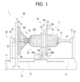
- Fig. 1 is an elevation view of a filament winding apparatus according to an embodiment of the present invention.
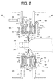
- Fig. 2 is an elevation view of a first guide member and a second guide member according to an embodiment of the present invention.
- Fig. 3 is an elevation view of a guide unit of the first guide member according to an embodiment of the present invention.
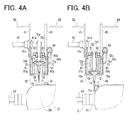
- Figs. 4A and 4B are elevation views of the first guide member and the second guide member according to an embodiment of the present invention.
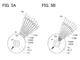
- Figs. 5A and 5B are side views of guide portions of the first guide members and the second guide members and liners according to an embodiment of the present invention.
- Figs. 6A, 6B, and 6C are enlarged views of leading end portions of the guide portions of the first and second guide members according to an embodiment of the present invention.
- a filament winding apparatus 1 according to an embodiment of the present invention will now be described.
- the filament winding apparatus 1 winds fiber bundles 35a and 45a around a liner 2 and includes a machine frame 10, a liner supporting unit 20, a hoop winding unit 30, and a helical winding unit 40.
- the liner 2 integrally includes a first cylindrical portion 2a having a constant radius, hemisphere portions 2b, 2b provided at both ends of the first cylindrical portion 2a, and second cylindrical portions 2c, 2c provided at end portions of the hemisphere portions 2b, 2b.
- the radius of the liner 2 continuously changes from the first cylindrical portion 2a to each of the hemisphere portions 2b and to each of the second cylindrical portions 2c.
- the radius of the second cylindrical portions 2c is smaller than that of the first cylindrical portion 2a.
- the liner 2 is composed of a metal container made of high-strength aluminum or stainless steel etc. or a plastic container made of polyamide resin etc., for example.
- the fiber bundle is composed of glass fiber or carbon fiber or the like.
- the machine frame 10 is a primal structure of the filament winding apparatus 1 and includes first rails 11, 11 that guide the liner 2 and second rails 12, 12 that guide the hoop winding unit 30.
- the first rails 11, 11 extend in one direction, and the second rails 12, 12 extend in the same direction as the first rails 11, 11.
- the liner supporting unit 20 includes a base 21 that is provided as a primal structure of the liner supporting unit 20 to support the liner 2, supporting boards 22, 22 that are individually fixed to the base 21 to sandwich the liner 2 therebetween, chucks 23, 23 that are attached to the respective supporting boards 22, 22, and shaft portions 24, 24 each having one end attached to the corresponding chuck 23 and the other end attached to the corresponding second cylindrical portion 2c, which is an end portion of the liner 2.
- the base 21 is arranged on the first rails 11, 11 and slidably reciprocated on the first rails 11, 11 by a first drive unit (not illustrated) composed of a motor and a pneumatic cylinder or a hydraulic cylinder, for example.
- the liner 2 is moved along with the base 21, in other words, the liner 2 is moved in an axial direction of the liner 2.
- the chuck 23 is rotatively driven by a second drive unit (not illustrated) composed of a motor etc., and a rotary drive force generated by the second drive unit is transmitted to the liner 2 via the chuck 23 and the shaft portion 24 to rotate the liner 2 about its axis.
- a second drive unit (not illustrated) composed of a motor etc.
- the hoop winding unit 30 performs a hoop winding operation, in which the fiber bundle is wound in such a manner that a longitudinal direction of the fiber bundle is substantially perpendicular to the axial direction of the liner 2.
- the hoop winding unit 30 includes: a frame 31 that is a primal structure of the hoop winding unit 30; a cylindrical portion 32 that penetrates through a penetration hole of the frame 31 and relatively rotates with respect to the frame 31; a rotary table 33 that is rotatably supported by the frame 31 by being attached to the cylindrical portion 32; a third drive unit (not illustrated) that moves the rotary table 33 along the second rails 12, 12; a fourth drive unit 34 that rotates the rotary table 33; and a first supply unit that supplies the liner 2 with the first fiber bundle 35a.
- the frame 31 is arranged on the second rails 12, 12 and reciprocated along the second rails 12, 12 by the third drive unit composed of a motor or a pneumatic cylinder or a hydraulic cylinder, for example.
- the rotary table 33 is moved along with the frame 31.
- the liner 2 is arranged on a trajectory of the rotary table 33 of the time when the table 33 is moved by the third drive unit, and the rotary table 33 has a first hole portion 33a, which is a penetration hole through which the liner 2 penetrates.
- the fourth drive unit 34 includes: a motor 34a that is provided as a drive source for rotating the rotary table 33; a motor gear 34b that is connected with the motor 34a; and a table gear 34c that is connected with the motor gear 34b and fixed to the rotary table 33.
- a motor 34a that is provided as a drive source for rotating the rotary table 33
- a motor gear 34b that is connected with the motor 34a
- a table gear 34c that is connected with the motor gear 34b and fixed to the rotary table 33.
- the first supply unit is provided to the rotary table 33 and includes bobbins 35b each having the first fiber bundle 35a wound around, a guide member (not illustrated) that is composed of a roller-shaped member etc. and that guides the first fiber bundle wound around the bobbin 35b to the liner 2, and a first resin impregnating unit (not illustrated) that injects resin to impregnate the first fiber bundle 35a with resin.
- Thermosetting synthetic resin such as epoxy resin
- the first fiber bundle 35a is fed from the bobbin 35b via the guide member and fixed to the liner 2 by adhesive tape or the like. Then, the third drive unit and the fourth drive unit 34 are operated, i.e., the hoop winding unit 30 is operated, and the rotary table 33 is moved along the second rails 12, 12 while being rotated at constant speed. As the liner 2 passes through the first hole portion 33a of the rotary table 33, the first fiber bundle 35a is guided by the guide member and wound around the liner 2. Immediately before the first fiber bundle 35a is wound around the liner 2, the first resin impregnating unit injects resin and impregnates the first fiber bundle 35a with resin. When the liner 2 reciprocates and passes through the first hole portion 33a prescribed number of times, layers of resin-impregnated fiber bundle 35a are formed around the liner 2, and thus the hoop winding operation is completed.
- the third drive unit and the fourth drive unit 34 are operated, i.e., the hoop winding unit 30 is operated, and
- the helical winding unit 40 performs a helical winding operation, in which the fiber bundle is wound such that a longitudinal direction of the fiber bundle is substantially parallel to the axial direction of the liner 2.
- the helical winding unit 40 includes: a first fixing frame 41 that is a primal structure of the helical winding unit 40; a first supporting ring 42 that is fixed to the first fixing frame 41; a first guide member 50 and a second guide member 60 that guide the second fiber bundle 45a supplied from a fiber bundle supply unit (not illustrated) to the liner 2; and a second resin impregnating unit (not illustrated) that injects resin and impregnates the second fiber bundle 45a with resin.
- the first supporting ring 42 has the shape of a disk and includes a concave portion 42a that is concave in the axial direction of the liner 2 (the liner 2 that is placed on the filament winding apparatus 1) (refer to Fig. 2 ).
- the first supporting ring 42 is provided on a trajectory of the liner of the time when the liner 2 is moved by the first drive unit, and is provided with a second hole portion, which is a penetration hole, at its central portion through which the liner 2 passes and penetrates.
- the second fiber bundle 45a is fed from the fiber bundle supply unit of the helical winding unit 40 via the first and second guide members 50 and 60 and fixed to the liner 2 by adhesive tape or the like.
- the first and second drive units are operated, i.e., the helical winding unit 40 is operated, and the liner 2 is moved along the first rails 11, 11 while being rotated at constant speed.
- the second fiber bundle 45a is guided by the first and second guide members 50 and 60 and wound around the liner 2.
- the second resin impregnating unit injects resin and impregnates the second fiber bundle 45a with resin.
- the liner 2 reciprocates and passes through the second hole portion prescribed number of times, layers of the resin-impregnated second fiber bundle 45a are formed around the liner 2, and thus the helical winding operation is completed.
- the first fiber bundle 35a and the second fiber bundle 45a both wound around the liner 2 are heated by a resin hardening furnace or the like, the impregnated resin of the first and second fiber bundles 35a and 45a is hardened, and a fiber-reinforced composite material is formed.
- a high-pressure tank or the like using the fiber-reinforced composite material is manufactured.
- the first guide member 50 of the helical winding unit 40 will now be described.
- the first guide member 50 includes a guide unit 70, a first rotation mechanism 80, and a first slide mechanism 90.
- the guide unit 70 is a primal portion of the first guide member 50, which implements a function of guiding the second fiber bundle 45a to the liner 2.
- the guide unit 70 includes a guide portion 71, a first supporting member 72, and a second supporting member 73.
- the guide portion 71 is a tubular member having a guide hole penetrated from a base end portion 71a to a leading end portion 71b.
- the guide portion 71 has a taper shape tapered off from a side of the base end portion 71a to a side of the leading end portion 71b and guides the second fiber bundle 45a to the liner 2 by having the second fiber bundle 45a run through the guide hole from the side of the base end portion 71a to the side of the leading end portion 71b.
- a first gear 71c which is a bevel gear, is fixed to the base end portion 71a of the guide portion 71. As illustrated in Figs.
- the leading end portion 71b has a flat oval shape, and a size T of a thickness direction is smaller than a size W of a width direction.
- the helical winding unit 40 includes a plurality of guide portions 71, which are radially aligned around the liner 2.
- the first supporting member 72 supports the guide portion 71 such that the guide portion 71 can rotate about its axis, and includes a protrusion 72a protruding in the axial direction of the liner 2.
- the first supporting member 72 includes a first penetration hole 72b.
- the first penetration hole 72b penetrates in a direction that is inclined towards the axial direction of the liner 2 with respect to a radius direction of the liner 2.
- the guide portion 71 By being penetrated through the first penetration hole 72b, the guide portion 71 is supported in a state in which the guide portion 71 can rotate about its axis and in which the guide portion 71 extends along the first penetration hole 72b, i.e., in a state in which an axial direction of the guide portion 71 is inclined with respect to the radius direction of the liner 2.
- the degree of the inclination of the guide portion 71 (that is, the inclination of the first penetration hole 72b) is properly determined in accordance with the quality of material and width of the second fiber bundle 45a, the length of the guide portion 71, and the distance from the guide portion 71 to the liner 2, for example.
- the first supporting member 72 includes a second penetration hole 72c that penetrates in the radius direction of the liner 2.
- a rod-shaped rotary shaft 72d is inserted into the second penetration hole 72c such that the rotary shaft 72d can rotate about its axis and the rotary shaft 72d extends in the radius direction of the liner 2.
- a second gear 72e which is a spur gear, is fixed to the rotary shaft 72d at a position where the second gear 72e engages with the first gear 71c of the guide portion 71.
- the rotary shaft 72d is inserted into and penetrates through a cylindrical socket 72f, which is connected with the rotary shaft 72d via a spline. Accordingly, the rotary shaft 72d can relatively slide with respect to the socket 72f in the axial direction of the rotary shaft 72d, i.e., in the radius direction of the liner 2, and can rotate about the axis of the rotary shaft 72d along with the socket 72f.
- the socket 72f is supported by the first supporting ring 42 such that the socket 72f can rotate about the axis of the rotary shaft 72d, and when the socket 72f is rotated, the rotation of the socket 72f is transmitted to the guide portion 71 via the rotary shaft 72d.
- First teeth 72g are formed on a circumferential surface of the socket 72f.
- the second supporting member 73 is a rod-shaped member that supports the first supporting member 72 such that the first supporting member 72 can slide in the radius direction of the liner 2, and resultantly supports the guide portion 71 such that the guide portion 71 can slide in the radius direction of the liner 2.
- the second supporting member 73 is fixed to the first supporting ring 42 along the radius direction of the liner 2.
- the first supporting member 72 includes a third penetration hole 72h that penetrates in the radius direction of the liner 2, and the second supporting member 73 is inserted into the third penetration hole 72h.
- the first supporting member 72 can slide in the axial direction of the second supporting member 73, that is, in the radius direction of the liner 2, and the guide portion 71 can resultantly slide.
- the helical winding unit 40 includes a plurality of guide units 70 radially aligned around the liner 2. As illustrated in Fig. 2 , the first rotation mechanism 80 rotates the guide portions 71 of the guide units 70 about their respective axes and includes a face gear 81 and a fifth drive unit 82.
- the face gear 81 has the shape of a disk and includes a penetration hole at its central portion through which the liner 2 is penetrated at the time of helical winding operation.
- the face gear 81 is externally fitted to the first supporting ring 42 and supported such that the face gear 81 can rotate about the axis of the liner 2.
- the face gear 81 includes second teeth 81a aligned along a circumferential portion of a disk surface thereof.
- the face gear 81 is arranged at a position where the second teeth 81a engage with the first teeth 72g of the sockets 72f of the guide units 70.
- the fifth drive unit 82 is a drive source that rotates the guide portions 71 about their respective axes and includes a motor etc.
- the fifth drive unit 82 is connected to the face gear 81, which is rotated by a prescribed angle when the fifth drive unit 82 is operated.
- the face gear 81 is rotated by the prescribed angle, rotation of the face gear 81 is transmitted to the guide portions 71 via the sockets 72f and the rotation shafts 72d, and thus the guide portions 71 are concurrently rotated about their respective axes.
- the first slide mechanism 90 is a member that slides the guide portions 71 in the radius direction of the liner 2 and includes a grooved cam 91 and a sixth drive unit 92.
- the grooved cam 91 has the shape of a disk and includes a penetration hole at its central portion through which the liner 2 passes at the time of helical winding operation.
- the grooved cam 91 is provided to the concave portion 42a of the first supporting ring 42 and supported such that the grooved cam 91 can rotate about the axis of the liner 2.
- the grooved cam 91 includes a plurality of grooves 91a on one of disk surfaces such that the grooves 91a are inclined towards a radius direction of the disk surface.
- the grooved cam 91 is arranged at a position where the protrusions 72a of the first supporting members 72 are inserted into the grooves 91a.
- a third gear 91b which is a spur gear, is fixed to the other disk surface of the grooved cam 91.
- the sixth drive unit 92 is a drive source that slides the guide portions 71 in the radius direction of the liner 2 and includes a motor etc.
- the sixth drive unit 92 is connected with the grooved cam 91 via a plurality of gears (i.e., via the third gear 91b, a fourth gear 91c, and a fifth gear 91d), and rotates the grooved cam 91 by a prescribed angle when operated.
- a prescribed angle As illustrated in Fig. 3 , when the grooved cam 91 is rotated by the prescribed angle, the protrusions 72a inserted into the grooves 91a, i.e., the first supporting members 72 are slid.
- the first supporting members 72 are supported by the second supporting members 73 slidably in the radius direction of the liner 2, the first supporting members 72 slide in the radius direction of the liner 2. Then, the guide portions 71 concurrently slide along with the first supporting members 72 in the radius direction of the liner 2.
- the second guide member 60 of the helical winding unit 40 will now be described.
- the second guide member 60 includes a second rotation mechanism 61, a second slide mechanism 62, and a phase change mechanism 63.
- the second guide member 60 is slightly separated away from the first guide member 50 in the axial direction of the liner 2.
- Guide units 70 of the second guide member 60 are attached to a second supporting ring 64.
- the second supporting ring 64 has the shape of a disk and includes a penetration hole at its central portion through which the liner 2 passes at the time of helical winding operation.
- the second supporting ring 64 is supported by a second fixing frame 65 such that the second supporting ring 64 can rotate about the axis of the liner 2.
- each of the leading end portions 71b of the guide portions 71 of the first guide member 50 and each of the leading end portions 71b of the guide portions 71 of the second guide member 60 is disposed between each of the leading end portions 71b of the guide portions 71 of the first guide member 50 ( Figs. 6A-6C ).
- the second rotation mechanism 61 rotates the guide portions 71 of the second guide member 60 about their respective axes, and includes a seventh drive unit 66.
- the seventh drive unit 66 is a drive source that rotates the guide portions 71 of the second guide member 60 and includes a motor etc. Rotation of the motor of the seventh drive unit 66 is transmitted to the guide portions 71 via a face gear 81 of the second guide member 60 when the seventh drive unit 66 is operated, and thus the guide portions 71 of the second guide member 60 are concurrently rotated about their respective axes.
- the second slide mechanism 62 slides the guide portions 71 of the second guide member 60 in the radius direction of the liner 2 and includes an eighth drive unit 67.
- the eighth drive unit 67 is a drive source that slides the guide portions 71 of the second guide member 60 in the radius direction of the liner 2 and includes a motor etc.
- rotation of the motor of the eight drive unit 67 is transmitted to the guide portions 71 via a grooved cam 91 etc. of the second guide member 60, and thus the guide portions 71 of the second guide member 60 concurrently slide in the radius direction of the liner 2.
- the phase change mechanism 63 changes phases of the guide portions 71 of the second guide member 60 around the axis of the liner 2 and includes a worm gear 68 and a ninth drive unit (not illustrated).
- the worm gear 68 is connected with the second supporting ring 64 via a plurality of gears (a sixth gear 68a and a seventh gear 68b).
- the ninth drive unit is a drive source that changes the phases of the guide portions 71 of the second guide member 60 around the axis of the liner 2 and includes a motor etc.
- the ninth drive unit is connected with the worm gear 68, and the second supporting ring 64 rotates about the axis of the liner 2 by a prescribed angle when the ninth drive unit is operated. Then, the guide portions 71 of the second guide member 60 are rotated about the axis of the liner 2 along with the second supporting ring 64. Thus, the phases of the guide portions 71 of the second guide member 60 change around the axis of the liner 2.
- Each of the fifth, sixth, seventh, and eighth drive units 82, 92, 66, and 67 is connected with a control unit (not illustrated) and individually controlled to operate/stop when a signal is transmitted from the control unit.
- the control unit includes a Central Processing Unit (CPU), a Read Only Memory (ROM), a Random Access Memory (RAM), and a Hard Disk Drive (HDD) or the like, which are mutually connected via a bus.
- the control unit stores various control programs and can develop these programs to perform prescribed calculations in accordance with the programs.
- FIG. 6A illustrates the leading end portions 71b of the guide portions 71 viewed from the direction of arrow A of Fig. 5A .
- Fig. 6C illustrates the leading end portions 71b of the guide portions 71 viewed from the direction of arrow A of Fig. 5B .
- the arrows of Figs. 6A through 6C correspond to the axial direction of the liner 2.
- the leading end portions 71b of the guide portions 71 of the first and second guide members 50, 60 are arranged such that the width direction of the leading end portions 71b are substantially perpendicular to the axis of the liner 2.
- each of the leading end portions 71b of the guide portions 71 of the first guide member 50 and each of the leading end portions 71b of the guide portions 71 of the second guide member 60 are alternately aligned.
- a distance X is maintained from each of the leading end portions 71b of the guide portions 71 of the first and second guide units 50, 60 to a circumferential surface of the first cylindrical portion 2a ( Fig. 5A ).
- the distance X is the most appropriate distance from each of the leading end portions 71b of the guide portions 71 to the circumferential surface of the first cylindrical portion 2a and is pre-set by experiment etc.
- the tension of the second fiber bundles 45a hardly fluctuates at the time of winding the second fiber bundles 45a, and the second fiber bundles 45a can be evenly wound around the liner 2.
- the control unit transmits a signal to the sixth and eighth drive units 92, 67 to slide the guide portions 71 of the first and second guide members 50, 60 towards the liner 2, and thus the distance X from each of the leading end portions 71b of the guide portions 71 of the first and second guide members 50, 60 to the circumferential surface of the first cylindrical portion 2a can be maintained.
- the control unit transmits a signal to the fifth and seventh drive units 82, 66 to rotate the guide portions 71 of the first and second guide members 50, 60 about their respective axes.
- the rotation direction is not particularly limited and may be properly set as long as the guide portions 71 approach the liner 2 in such a state that the phase of each of the guide portions 71 around the axis is kept as illustrated in Fig. 6A .
- the control unit transmits a signal to the ninth drive unit to rotate the guide portions 71 of the second guide member 60 about the axis of the liner 2, and thus maintains the arrangement in which each of the leading end portions 71b of the guide portions 71 of the first guide member 50 and each of the leading end portions 71b of the guide portions 71 of the second guide member 60 are alternately aligned. Accordingly, the leading end portions 71b can be prevented from being collided with each other.
- each of the leading end portions 71b of the guide portions 71 of the first and second guide members 50, 60 is arranged to overlap with each other in the thickness direction.
- the thickness direction of the leading end portions 71b of the guide portions 71 is set to be substantially perpendicular to the axis of the liner 2, and the adjacent leading end portions 71b make contact with each other.
- each of the leading end portions 71b of the guide portions 71 of the first guide member 50 and each of the leading end portions 71b of the guide portions 71 of the second guide member 60 are alternately aligned.
- the control unit performs the control of processes (1) through (3) as described below while the portion to which the second fiber bundles 45a are guided changes from the hemisphere portion 2b to the second cylindrical portion 2c of the liner 2, and arranges each of the leading end portions 71b of the guide portions 71 of the first guide member 50 and each of the leading end portions 71b of the guide portions 71 of the second guide member 60 to overlap in the thickness direction.
- the guide portions 71 can be brought closer to the liner 2, and a range of movement of the guide portions 71 increases. Accordingly, the distance X from each of the leading end portions 71b of the guide portions 71 to the circumferential surface of the second cylindrical portion 2c of the liner 2 can be easily maintained.
- the filament winding apparatus 1 includes a plurality of guide portions 71, each of which is a tubular member having the guide hole penetrated from the base end portion 71a to the leading end portion 71b, has the size T in the thickness direction of the leading end portion 71b that is smaller than the size W in the width direction, and guides the second fiber bundle 45a from the side of the base end portion 71a of the guide hole to the side of the leading end portion 71b to guide the second fiber bundle 45a to the liner 2. Moreover, the filament winding apparatus 1 rotates the guide portions 71 about their respective axes and slides the guide portions 71 in the radius direction of the liner 2 to bring them close to the liner 2.
- the guide portions 71 can be brought close to the liner 2 until the leading end portions 71b of the guide portions 71 overlap in the thickness direction. As a result, the variation of the distance from the liner 2 to each of the guide portions 71 can be reduced, and fluctuations in the winding operation can also be reduced.
- the filament winding apparatus 1 further includes: the plurality of guide units 70 each having the first supporting member 72 that supports the guide portion 71 such that the guide portion 71 can rotate about its axis and the second supporting member 73 that supports the first supporting member 72 such that the first supporting member 72 can slide in the radius direction of the liner 2; the first rotation mechanism 80 (the second rotation mechanism 61) that rotates the guide portions 71 about their respective axes; and the first slide mechanism 90 (the second slide mechanism 62) that slides the first supporting members 72 in the radius direction of the liner 2.
- the guide portions 71 can be brought close to the liner 2 until the leading end portions 71b of the guide portions 71 overlap in the thickness direction.
- the variation of the distance from the liner 2 to each of the guide portions 71 can be further reduced, and the fluctuations in the winding operation can also be reduced.
- the filament winding apparatus 1 includes the phase change mechanism 63 that divides the guide portions 71 into a plurality of groups, i.e., into the group of the guide portions 71 of the first guide member 50 and the group of the guide portions 71 of the second guide member 60 and changes the phases of the guide portions 71 of the second guide member 60 around the axis of the liner 2.
- the guide portions 71 of the first and second guide members 50, 60 can be brought close to the liner 2 until the guide portions 71 of the first and second guide members 50, 60 overlap in the thickness direction, and the second fiber bundles 45a guided from the guide portions 71 of the first and second guide members 50, 60 can be wound around the liner 2.
- the variation of the distance from the liner 2 to each of the guide portions 71 of the first and second guide members 50, 60 can be reduced, the fluctuations in the winding operation can be also reduced, and a greater number of second fiber bundles 45a can be wound around the liner 2.
- the first supporting members 72 slide with respect to the second supporting members 73 such that the distance from the leading end portions 71b of the guide portions 71 to the liner 2 can be maintained constant.
- the second fiber bundles 45a can be wound around the liner 2 while maintaining the tension of the second fiber bundles 45a constant, and the fluctuations in the winding operation can be reduced.
Landscapes
- Engineering & Computer Science (AREA)
- Mechanical Engineering (AREA)
- Moulding By Coating Moulds (AREA)
Abstract
Description
- The present invention relates to a filament winding apparatus.
- A well-known filament winding apparatus includes a hoop winding unit and a helical winding unit and forms reinforced layers by alternately performing a hoop winding operation by the hoop winding unit and a helical winding operation by the helical winding unit repeatedly on a liner and thus winding fiber bundles around the liner.
- When the helical winding unit performs the helical winding operation, the liner moves in an axial direction while being rotated at constant speed, and the fiber bundle is supplied from the helical winding unit and wound around the liner. In a conventional art, when the fiber bundle is wound around the liner, the fiber bundle is guided from a guide portion of the helical winding unit to the liner (for example, refer to
JP,2000-108212,A - However, some liners have a smaller radius at both end portions than at a central portion. When the fiber bundle is wound around such liners, a distance from the liner to the guide portion varies between the case of winding the fiber bundle around the end portions and the case of winding the fiber bundle around the central portion. When the distance from the liner to the guide portion varies, a tension of the fiber bundle fluctuates, resulting in fluctuations in the winding operation, i.e., an amount of wound fiber bundle varies depending on a position of the liner.
- In view of the above, an apparatus has been developed which reduces the fluctuations in the winding operation by approximating the guide portion in a radius direction of the liner and by resultantly reducing the variation (an amount of change) of the distance between the liner and the guide portion when the portion to have the fiber bundle wound around changes from the central portion to the end portions of the liner.
- However, a plurality of guide portions are usually provided around the liner. As a result, a leading end portion of each of the guide portions collides and interferes with each other when the guide portions are moved in the radius direction of the liner to be close to the liner, and therefore, there are limitations to the reduction of the variation of the distance from the liner to the guide portions.
- In order to overcome the problems described above, the present invention provides a filament winding apparatus that can reduce fluctuations in a winding operation by reducing the variation of a distance from a liner to a plurality of guide portions.
- The problems to be overcome by the present invention have been described, and a method of solving the problems will be described below.
- According to an embodiment of the present invention, a filament winding apparatus includes a plurality of guide portions that are tubular members each having a guide hole penetrated from a base end portion to a leading end portion. The leading end portion has a smaller size in a thickness direction than in a width direction. Each of the guide portions guides a fiber bundle to a liner by passing the fiber bundle from a side of the base end portion to a side of the leading end portion of the guide hole. The filament winding apparatus rotates the guide portions about their respective axes and also brings the guide portions close to the liner by moving the guide portions in a radius direction of the liner.
- According to an embodiment of the present invention, the filament winding apparatus includes: a first supporting member that supports the guide portion such that the guide portion can rotate about its axis; a second supporting member that supports the first supporting member such that the first supporting member can slide in the radius direction of the liner; a rotation mechanism that rotates the guide portion about its axis; and a slide mechanism that slides the first supporting member in the radius direction of the liner.
- The filament winding apparatus according to an embodiment of the present invention includes a phase change mechanism that divides the guide portions into a plurality of groups and changes phases around an axis of the liner with respect to each group.
- In the filament winding apparatus according to an embodiment of the present invention, the first supporting member slides with respect to the second supporting member such that a distance from the leading end portion of the guide portion to the liner is maintained constant.
- In the filament winding apparatus according to an embodiment of the present invention, by bringing the guide portions close to the liner while rotating the leading end portions of the guide portions about their respective axes, the guide portions can be brought close to the liner until the leading end portions of the guide portions overlap in the thickness direction. Accordingly, the variation of the distance between the liner and each of the guide portions can be reduced, which thereby reduces fluctuations in a winding operation.
- In the filament winding apparatus according to an embodiment of the present invention, by rotating the guide portions about their respective axes by the rotation mechanism, and by sliding the first supporting members, i.e., by sliding the guide portions in the radius direction of the liner by the slide mechanism, the guide portions can be brought close to the liner until the leading end portions of the guide portions overlap in the thickness direction. Accordingly, the variation of the distance between the liner and each of the guide portions can be reduced, which thereby reduces fluctuations in a winding operation.
- In the filament winding apparatus according to an embodiment of the present invention, by bringing the guide portions close to the liner while rotating the leading end portions of the guide portions about their respective axes, and by changing the phases around the axis of the liner with respect to each of the plurality of groups by the phase change mechanism, the guide portions can be brought close to the liner until the leading end portions of the guide portions overlap in the thickness direction, and the fiber bundles guided from the guide portions of the plurality of groups can be wound around the liner. Accordingly, the variation of the distance between the liner and each of the guide portions can be further reduced, fluctuations in the winding operation can also be reduced, and a greater number of fiber bundles can be wound around the liner.
- In the filament winding apparatus according to an embodiment of the present invention, since the distance from each of the leading end portions of the guide portions to the liner can be maintained constant, the fiber bundles can be wound around the liner while maintaining the tension of the fiber bundles constant, and fluctuations in the winding operation can be reduced.
-
Fig. 1 is an elevation view of a filament winding apparatus according to an embodiment of the present invention. -
Fig. 2 is an elevation view of a first guide member and a second guide member according to an embodiment of the present invention. -
Fig. 3 is an elevation view of a guide unit of the first guide member according to an embodiment of the present invention. -
Figs. 4A and 4B are elevation views of the first guide member and the second guide member according to an embodiment of the present invention. -
Figs. 5A and 5B are side views of guide portions of the first guide members and the second guide members and liners according to an embodiment of the present invention. -
Figs. 6A, 6B, and 6C are enlarged views of leading end portions of the guide portions of the first and second guide members according to an embodiment of the present invention. - A filament winding apparatus 1 according to an embodiment of the present invention will now be described.
- As illustrated in
Fig. 1 , the filament winding apparatus 1winds fiber bundles liner 2 and includes amachine frame 10, aliner supporting unit 20, ahoop winding unit 30, and ahelical winding unit 40. Theliner 2 integrally includes a first cylindrical portion 2a having a constant radius, hemisphere portions 2b, 2b provided at both ends of the first cylindrical portion 2a, and secondcylindrical portions liner 2 continuously changes from the first cylindrical portion 2a to each of the hemisphere portions 2b and to each of the secondcylindrical portions 2c. The radius of the secondcylindrical portions 2c is smaller than that of the first cylindrical portion 2a. Theliner 2 is composed of a metal container made of high-strength aluminum or stainless steel etc. or a plastic container made of polyamide resin etc., for example. The fiber bundle is composed of glass fiber or carbon fiber or the like. - The
machine frame 10 is a primal structure of the filament winding apparatus 1 and includes first rails 11, 11 that guide theliner 2 andsecond rails hoop winding unit 30. The first rails 11, 11 extend in one direction, and thesecond rails - The
liner supporting unit 20 includes abase 21 that is provided as a primal structure of theliner supporting unit 20 to support theliner 2, supportingboards base 21 to sandwich theliner 2 therebetween, chucks 23, 23 that are attached to the respective supportingboards shaft portions corresponding chuck 23 and the other end attached to the corresponding secondcylindrical portion 2c, which is an end portion of theliner 2. - The
base 21 is arranged on the first rails 11, 11 and slidably reciprocated on the first rails 11, 11 by a first drive unit (not illustrated) composed of a motor and a pneumatic cylinder or a hydraulic cylinder, for example. Theliner 2 is moved along with thebase 21, in other words, theliner 2 is moved in an axial direction of theliner 2. - The
chuck 23 is rotatively driven by a second drive unit (not illustrated) composed of a motor etc., and a rotary drive force generated by the second drive unit is transmitted to theliner 2 via thechuck 23 and theshaft portion 24 to rotate theliner 2 about its axis. - The
hoop winding unit 30 performs a hoop winding operation, in which the fiber bundle is wound in such a manner that a longitudinal direction of the fiber bundle is substantially perpendicular to the axial direction of theliner 2. Thehoop winding unit 30 includes: aframe 31 that is a primal structure of thehoop winding unit 30; acylindrical portion 32 that penetrates through a penetration hole of theframe 31 and relatively rotates with respect to theframe 31; a rotary table 33 that is rotatably supported by theframe 31 by being attached to thecylindrical portion 32; a third drive unit (not illustrated) that moves the rotary table 33 along thesecond rails fourth drive unit 34 that rotates the rotary table 33; and a first supply unit that supplies theliner 2 with thefirst fiber bundle 35a. - The
frame 31 is arranged on thesecond rails second rails frame 31. Theliner 2 is arranged on a trajectory of the rotary table 33 of the time when the table 33 is moved by the third drive unit, and the rotary table 33 has afirst hole portion 33a, which is a penetration hole through which theliner 2 penetrates. - The
fourth drive unit 34 includes: amotor 34a that is provided as a drive source for rotating the rotary table 33; amotor gear 34b that is connected with themotor 34a; and atable gear 34c that is connected with themotor gear 34b and fixed to the rotary table 33. When themotor 34a is rotated, the rotary table 33 is also rotated. - The first supply unit is provided to the rotary table 33 and includes
bobbins 35b each having thefirst fiber bundle 35a wound around, a guide member (not illustrated) that is composed of a roller-shaped member etc. and that guides the first fiber bundle wound around thebobbin 35b to theliner 2, and a first resin impregnating unit (not illustrated) that injects resin to impregnate thefirst fiber bundle 35a with resin. Thermosetting synthetic resin (such as epoxy resin) may be used as resin, for example. - When the
hoop winding unit 30 performs a hoop winding operation, thefirst fiber bundle 35a is fed from thebobbin 35b via the guide member and fixed to theliner 2 by adhesive tape or the like. Then, the third drive unit and thefourth drive unit 34 are operated, i.e., thehoop winding unit 30 is operated, and the rotary table 33 is moved along thesecond rails liner 2 passes through thefirst hole portion 33a of the rotary table 33, thefirst fiber bundle 35a is guided by the guide member and wound around theliner 2. Immediately before thefirst fiber bundle 35a is wound around theliner 2, the first resin impregnating unit injects resin and impregnates thefirst fiber bundle 35a with resin. When theliner 2 reciprocates and passes through thefirst hole portion 33a prescribed number of times, layers of resin-impregnatedfiber bundle 35a are formed around theliner 2, and thus the hoop winding operation is completed. - The helical winding
unit 40 performs a helical winding operation, in which the fiber bundle is wound such that a longitudinal direction of the fiber bundle is substantially parallel to the axial direction of theliner 2. The helical windingunit 40 includes: afirst fixing frame 41 that is a primal structure of the helical windingunit 40; a first supportingring 42 that is fixed to thefirst fixing frame 41; afirst guide member 50 and asecond guide member 60 that guide thesecond fiber bundle 45a supplied from a fiber bundle supply unit (not illustrated) to theliner 2; and a second resin impregnating unit (not illustrated) that injects resin and impregnates thesecond fiber bundle 45a with resin. The first supportingring 42 has the shape of a disk and includes aconcave portion 42a that is concave in the axial direction of the liner 2 (theliner 2 that is placed on the filament winding apparatus 1) (refer toFig. 2 ). The first supportingring 42 is provided on a trajectory of the liner of the time when theliner 2 is moved by the first drive unit, and is provided with a second hole portion, which is a penetration hole, at its central portion through which theliner 2 passes and penetrates. - When the helical winding
unit 40 performs the helical winding operation, thesecond fiber bundle 45a is fed from the fiber bundle supply unit of the helical windingunit 40 via the first andsecond guide members liner 2 by adhesive tape or the like. Then, the first and second drive units are operated, i.e., the helical windingunit 40 is operated, and theliner 2 is moved along the first rails 11, 11 while being rotated at constant speed. As theliner 2 passes through the second hole portion of the first supportingring 42, thesecond fiber bundle 45a is guided by the first andsecond guide members liner 2. Immediately before thesecond fiber bundle 45a is wound around theliner 2, the second resin impregnating unit injects resin and impregnates thesecond fiber bundle 45a with resin. When theliner 2 reciprocates and passes through the second hole portion prescribed number of times, layers of the resin-impregnatedsecond fiber bundle 45a are formed around theliner 2, and thus the helical winding operation is completed. - After the hoop winding operation by the
hoop winding unit 30 and the helical winding operation by the helical windingunit 40 are alternately performed prescribed number of times, thefirst fiber bundle 35a and thesecond fiber bundle 45a both wound around theliner 2 are heated by a resin hardening furnace or the like, the impregnated resin of the first andsecond fiber bundles - The
first guide member 50 of the helical windingunit 40 will now be described. - As illustrated in
Fig. 2 , thefirst guide member 50 includes aguide unit 70, afirst rotation mechanism 80, and a first slide mechanism 90. - As illustrated in
Figs. 2 and3 , theguide unit 70 is a primal portion of thefirst guide member 50, which implements a function of guiding thesecond fiber bundle 45a to theliner 2. Theguide unit 70 includes aguide portion 71, a first supportingmember 72, and a second supportingmember 73. - As illustrated in
Fig. 3 , theguide portion 71 is a tubular member having a guide hole penetrated from abase end portion 71a to aleading end portion 71b. Theguide portion 71 has a taper shape tapered off from a side of thebase end portion 71a to a side of theleading end portion 71b and guides thesecond fiber bundle 45a to theliner 2 by having thesecond fiber bundle 45a run through the guide hole from the side of thebase end portion 71a to the side of theleading end portion 71b. Afirst gear 71c, which is a bevel gear, is fixed to thebase end portion 71a of theguide portion 71.
As illustrated inFigs. 6A, 6B, and 6C , theleading end portion 71b has a flat oval shape, and a size T of a thickness direction is smaller than a size W of a width direction.
The helical windingunit 40 includes a plurality ofguide portions 71, which are radially aligned around theliner 2. - As illustrated in
Fig. 3 , the first supportingmember 72 supports theguide portion 71 such that theguide portion 71 can rotate about its axis, and includes aprotrusion 72a protruding in the axial direction of theliner 2.
The first supportingmember 72 includes a first penetration hole 72b. The first penetration hole 72b penetrates in a direction that is inclined towards the axial direction of theliner 2 with respect to a radius direction of theliner 2. - By being penetrated through the first penetration hole 72b, the
guide portion 71 is supported in a state in which theguide portion 71 can rotate about its axis and in which theguide portion 71 extends along the first penetration hole 72b, i.e., in a state in which an axial direction of theguide portion 71 is inclined with respect to the radius direction of theliner 2. The degree of the inclination of the guide portion 71 (that is, the inclination of the first penetration hole 72b) is properly determined in accordance with the quality of material and width of thesecond fiber bundle 45a, the length of theguide portion 71, and the distance from theguide portion 71 to theliner 2, for example. - The first supporting
member 72 includes asecond penetration hole 72c that penetrates in the radius direction of theliner 2. A rod-shapedrotary shaft 72d is inserted into thesecond penetration hole 72c such that therotary shaft 72d can rotate about its axis and therotary shaft 72d extends in the radius direction of theliner 2. - A
second gear 72e, which is a spur gear, is fixed to therotary shaft 72d at a position where thesecond gear 72e engages with thefirst gear 71c of theguide portion 71.
Therotary shaft 72d is inserted into and penetrates through acylindrical socket 72f, which is connected with therotary shaft 72d via a spline. Accordingly, therotary shaft 72d can relatively slide with respect to thesocket 72f in the axial direction of therotary shaft 72d, i.e., in the radius direction of theliner 2, and can rotate about the axis of therotary shaft 72d along with thesocket 72f. - The
socket 72f is supported by the first supportingring 42 such that thesocket 72f can rotate about the axis of therotary shaft 72d, and when thesocket 72f is rotated, the rotation of thesocket 72f is transmitted to theguide portion 71 via therotary shaft 72d.
First teeth 72g are formed on a circumferential surface of thesocket 72f. - The second supporting
member 73 is a rod-shaped member that supports the first supportingmember 72 such that the first supportingmember 72 can slide in the radius direction of theliner 2, and resultantly supports theguide portion 71 such that theguide portion 71 can slide in the radius direction of theliner 2. The second supportingmember 73 is fixed to the first supportingring 42 along the radius direction of theliner 2. The first supportingmember 72 includes athird penetration hole 72h that penetrates in the radius direction of theliner 2, and the second supportingmember 73 is inserted into thethird penetration hole 72h. Thus, the first supportingmember 72 can slide in the axial direction of the second supportingmember 73, that is, in the radius direction of theliner 2, and theguide portion 71 can resultantly slide. - The helical winding
unit 40 includes a plurality ofguide units 70 radially aligned around theliner 2. As illustrated inFig. 2 , thefirst rotation mechanism 80 rotates theguide portions 71 of theguide units 70 about their respective axes and includes aface gear 81 and a fifth drive unit 82. - The
face gear 81 has the shape of a disk and includes a penetration hole at its central portion through which theliner 2 is penetrated at the time of helical winding operation. Theface gear 81 is externally fitted to the first supportingring 42 and supported such that theface gear 81 can rotate about the axis of theliner 2.
As illustrated inFig. 3 , theface gear 81 includes second teeth 81a aligned along a circumferential portion of a disk surface thereof. Theface gear 81 is arranged at a position where the second teeth 81a engage with the first teeth 72g of thesockets 72f of theguide units 70. - As illustrated in
Fig. 2 , the fifth drive unit 82 is a drive source that rotates theguide portions 71 about their respective axes and includes a motor etc. The fifth drive unit 82 is connected to theface gear 81, which is rotated by a prescribed angle when the fifth drive unit 82 is operated. When theface gear 81 is rotated by the prescribed angle, rotation of theface gear 81 is transmitted to theguide portions 71 via thesockets 72f and therotation shafts 72d, and thus theguide portions 71 are concurrently rotated about their respective axes. - The first slide mechanism 90 is a member that slides the
guide portions 71 in the radius direction of theliner 2 and includes agrooved cam 91 and asixth drive unit 92. - As illustrated in
Figs. 2 and3 , thegrooved cam 91 has the shape of a disk and includes a penetration hole at its central portion through which theliner 2 passes at the time of helical winding operation. Thegrooved cam 91 is provided to theconcave portion 42a of the first supportingring 42 and supported such that thegrooved cam 91 can rotate about the axis of theliner 2. Thegrooved cam 91 includes a plurality ofgrooves 91a on one of disk surfaces such that thegrooves 91a are inclined towards a radius direction of the disk surface. Thegrooved cam 91 is arranged at a position where theprotrusions 72a of the first supportingmembers 72 are inserted into thegrooves 91a. Athird gear 91b, which is a spur gear, is fixed to the other disk surface of thegrooved cam 91. - As illustrated in
Fig. 2 , thesixth drive unit 92 is a drive source that slides theguide portions 71 in the radius direction of theliner 2 and includes a motor etc. Thesixth drive unit 92 is connected with thegrooved cam 91 via a plurality of gears (i.e., via thethird gear 91b, afourth gear 91c, and afifth gear 91d), and rotates the groovedcam 91 by a prescribed angle when operated.
As illustrated inFig. 3 , when thegrooved cam 91 is rotated by the prescribed angle, theprotrusions 72a inserted into thegrooves 91a, i.e., the first supportingmembers 72 are slid. At this time, since the first supportingmembers 72 are supported by the second supportingmembers 73 slidably in the radius direction of theliner 2, the first supportingmembers 72 slide in the radius direction of theliner 2.
Then, theguide portions 71 concurrently slide along with the first supportingmembers 72 in the radius direction of theliner 2. - The
second guide member 60 of the helical windingunit 40 will now be described. - As illustrated in
Fig. 2 , thesecond guide member 60 includes a second rotation mechanism 61, asecond slide mechanism 62, and aphase change mechanism 63. - The
second guide member 60 is slightly separated away from thefirst guide member 50 in the axial direction of theliner 2. -
Guide units 70 of thesecond guide member 60 are attached to a second supportingring 64. The second supportingring 64 has the shape of a disk and includes a penetration hole at its central portion through which theliner 2 passes at the time of helical winding operation. The second supportingring 64 is supported by asecond fixing frame 65 such that the second supportingring 64 can rotate about the axis of theliner 2. - By alternately arranging each of the
leading end portions 71b of theguide portions 71 of thefirst guide member 50 and each of theleading end portions 71b of theguide portions 71 of thesecond guide member 60, i.e., by having different phases around the axis of theliner 2 between theguide portions 71 of thefirst guide member 50 and theguide portions 71 of thesecond guide member 60, each of theleading end portions 71b of theguide portions 71 of thesecond guide member 60 is disposed between each of theleading end portions 71b of theguide portions 71 of the first guide member 50 (Figs. 6A-6C ). - The second rotation mechanism 61 rotates the
guide portions 71 of thesecond guide member 60 about their respective axes, and includes a seventh drive unit 66.
The seventh drive unit 66 is a drive source that rotates theguide portions 71 of thesecond guide member 60 and includes a motor etc. Rotation of the motor of the seventh drive unit 66 is transmitted to theguide portions 71 via aface gear 81 of thesecond guide member 60 when the seventh drive unit 66 is operated, and thus theguide portions 71 of thesecond guide member 60 are concurrently rotated about their respective axes. - The
second slide mechanism 62 slides theguide portions 71 of thesecond guide member 60 in the radius direction of theliner 2 and includes aneighth drive unit 67.
Theeighth drive unit 67 is a drive source that slides theguide portions 71 of thesecond guide member 60 in the radius direction of theliner 2 and includes a motor etc. When theeighth drive unit 67 is operated, rotation of the motor of the eightdrive unit 67 is transmitted to theguide portions 71 via agrooved cam 91 etc. of thesecond guide member 60, and thus theguide portions 71 of thesecond guide member 60 concurrently slide in the radius direction of theliner 2. - The
phase change mechanism 63 changes phases of theguide portions 71 of thesecond guide member 60 around the axis of theliner 2 and includes aworm gear 68 and a ninth drive unit (not illustrated). - The
worm gear 68 is connected with the second supportingring 64 via a plurality of gears (asixth gear 68a and aseventh gear 68b).
The ninth drive unit is a drive source that changes the phases of theguide portions 71 of thesecond guide member 60 around the axis of theliner 2 and includes a motor etc. The ninth drive unit is connected with theworm gear 68, and the second supportingring 64 rotates about the axis of theliner 2 by a prescribed angle when the ninth drive unit is operated.
Then, theguide portions 71 of thesecond guide member 60 are rotated about the axis of theliner 2 along with the second supportingring 64. Thus, the phases of theguide portions 71 of thesecond guide member 60 change around the axis of theliner 2. - Each of the fifth, sixth, seventh, and
eighth drive units - A displacement (positional change) of the
guide portions 71 at the time of helical winding operation by the helical windingunit 40 will now be described.
Assume that thesecond fiber bundles 45a are wound around theliner 2 from the first cylindrical portion 2a, the hemisphere portion 2b, and to the secondcylindrical portion 2c in this order.
Fig. 6A illustrates theleading end portions 71b of theguide portions 71 viewed from the direction of arrow A ofFig. 5A .
Fig. 6C illustrates theleading end portions 71b of theguide portions 71 viewed from the direction of arrow A ofFig. 5B .
The arrows ofFigs. 6A through 6C correspond to the axial direction of theliner 2. - As illustrated in
Figs. 4A and5A , when thesecond fiber bundles 45a are wound around the first cylindrical portion 2a of theliner 2, theleading end portions 71b of theguide portions 71 of the first andsecond guide members leading end portions 71b are substantially perpendicular to the axis of theliner 2.
As illustrated inFig. 6A , each of theleading end portions 71b of theguide portions 71 of thefirst guide member 50 and each of theleading end portions 71b of theguide portions 71 of thesecond guide member 60 are alternately aligned.
A distance X is maintained from each of theleading end portions 71b of theguide portions 71 of the first andsecond guide units Fig. 5A ). The distance X is the most appropriate distance from each of theleading end portions 71b of theguide portions 71 to the circumferential surface of the first cylindrical portion 2a and is pre-set by experiment etc. Moreover, with the distance X, the tension of thesecond fiber bundles 45a hardly fluctuates at the time of winding thesecond fiber bundles 45a, and thesecond fiber bundles 45a can be evenly wound around theliner 2. - When the
second bundles 45a are wound around the hemisphere portion 2b of theliner 2, the control unit transmits a signal to the sixth andeighth drive units guide portions 71 of the first andsecond guide members liner 2, and thus the distance X from each of theleading end portions 71b of theguide portions 71 of the first andsecond guide members
As illustrated inFig. 6B , the control unit transmits a signal to the fifth and seventh drive units 82, 66 to rotate theguide portions 71 of the first andsecond guide members guide portions 71 approach theliner 2 in such a state that the phase of each of theguide portions 71 around the axis is kept as illustrated inFig. 6A .
The control unit transmits a signal to the ninth drive unit to rotate theguide portions 71 of thesecond guide member 60 about the axis of theliner 2, and thus maintains the arrangement in which each of theleading end portions 71b of theguide portions 71 of thefirst guide member 50 and each of theleading end portions 71b of theguide portions 71 of thesecond guide member 60 are alternately aligned. Accordingly, theleading end portions 71b can be prevented from being collided with each other. - As illustrated in
Figs 4B ,5B , and6C , when each of thesecond fiber bundles 45a is wound around the secondcylindrical portion 2c of theliner 2, each of theleading end portions 71b of theguide portions 71 of the first andsecond guide members leading end portions 71b overlap with each other in the thickness direction, the thickness direction of theleading end portions 71b of theguide portions 71 is set to be substantially perpendicular to the axis of theliner 2, and the adjacentleading end portions 71b make contact with each other.
Each of theleading end portions 71b of theguide portions 71 of thefirst guide member 50 and each of theleading end portions 71b of theguide portions 71 of thesecond guide member 60 are alternately aligned.
In other words, the control unit performs the control of processes (1) through (3) as described below while the portion to which thesecond fiber bundles 45a are guided changes from the hemisphere portion 2b to the secondcylindrical portion 2c of theliner 2, and arranges each of theleading end portions 71b of theguide portions 71 of thefirst guide member 50 and each of theleading end portions 71b of theguide portions 71 of thesecond guide member 60 to overlap in the thickness direction. - (1) The control unit transmits a signal to the ninth drive unit to maintain the state in which each of the
leading end portions 71b of theguide portions 71 of thefirst guide member 50 and each of theleading end portions 71b of theguide portions 71 of thesecond guide member 60 are alternately aligned. - (2) The control unit transmits a signal to the fifth and seventh drive units 82, 66 to rotate the
guide portions 71 until the thickness direction of each of theleading end portions 71b of the first andsecond guide members liner 2. - (3) The control unit transmits a signal to the sixth and
eighth drive units guide portions 71 towards theliner 2 to the position where each of the adjacentleading end portions 71b of theguide portions 71 of the first andsecond guide members - With the above arrangement, compared with the case in which the
guide portions 71 are brought close to theliner 2 without being rotated about their respective axes from the state in which thesecond fiber bundles 45a are wound around the first cylindrical portion 2a of the liner 2 (Fig. 6A ), theguide portions 71 can be brought closer to theliner 2, and a range of movement of theguide portions 71 increases. Accordingly, the distance X from each of theleading end portions 71b of theguide portions 71 to the circumferential surface of the secondcylindrical portion 2c of theliner 2 can be easily maintained. - As described above, the filament winding apparatus 1 includes a plurality of
guide portions 71, each of which is a tubular member having the guide hole penetrated from thebase end portion 71a to theleading end portion 71b, has the size T in the thickness direction of theleading end portion 71b that is smaller than the size W in the width direction, and guides thesecond fiber bundle 45a from the side of thebase end portion 71a of the guide hole to the side of theleading end portion 71b to guide thesecond fiber bundle 45a to theliner 2. Moreover, the filament winding apparatus 1 rotates theguide portions 71 about their respective axes and slides theguide portions 71 in the radius direction of theliner 2 to bring them close to theliner 2.
With the above configuration, theguide portions 71 can be brought close to theliner 2 until theleading end portions 71b of theguide portions 71 overlap in the thickness direction. As a result, the variation of the distance from theliner 2 to each of theguide portions 71 can be reduced, and fluctuations in the winding operation can also be reduced. - The filament winding apparatus 1 further includes: the plurality of
guide units 70 each having the first supportingmember 72 that supports theguide portion 71 such that theguide portion 71 can rotate about its axis and the second supportingmember 73 that supports the first supportingmember 72 such that the first supportingmember 72 can slide in the radius direction of theliner 2; the first rotation mechanism 80 (the second rotation mechanism 61) that rotates theguide portions 71 about their respective axes; and the first slide mechanism 90 (the second slide mechanism 62) that slides the first supportingmembers 72 in the radius direction of theliner 2.
With the above configuration, by rotating theguide portions 71 about their respective axes by thefirst rotation mechanism 80, and by sliding the first supportingmembers 72, i.e., theguide portions 71 in the radius direction of theliner 2 by the first slide mechanism 90, theguide portions 71 can be brought close to theliner 2 until theleading end portions 71b of theguide portions 71 overlap in the thickness direction. As a result, the variation of the distance from theliner 2 to each of theguide portions 71 can be further reduced, and the fluctuations in the winding operation can also be reduced. - The filament winding apparatus 1 includes the
phase change mechanism 63 that divides theguide portions 71 into a plurality of groups, i.e., into the group of theguide portions 71 of thefirst guide member 50 and the group of theguide portions 71 of thesecond guide member 60 and changes the phases of theguide portions 71 of thesecond guide member 60 around the axis of theliner 2.
With the above configuration, by bringing theguide portions 71 close to theliner 2 while overlapping theleading end portions 71b of theguide portions 71 in the thickness direction, and by changing the phases of theguide portions 71 of thesecond guide member 60 around the axis of theliner 2 by thephase change mechanism 63, theguide portions 71 of the first andsecond guide members liner 2 until theguide portions 71 of the first andsecond guide members second fiber bundles 45a guided from theguide portions 71 of the first andsecond guide members liner 2. Accordingly, the variation of the distance from theliner 2 to each of theguide portions 71 of the first andsecond guide members second fiber bundles 45a can be wound around theliner 2. - The first supporting
members 72 slide with respect to the second supportingmembers 73 such that the distance from theleading end portions 71b of theguide portions 71 to theliner 2 can be maintained constant.
With the above configuration, since the distance from theleading end portions 71b of theguide portions 71 to theliner 2 can be maintained, thesecond fiber bundles 45a can be wound around theliner 2 while maintaining the tension of thesecond fiber bundles 45a constant, and the fluctuations in the winding operation can be reduced.
Claims (4)
- A filament winding apparatus that winds fiber bundles around a liner, the apparatus comprising a plurality of guide portions, whereineach of the guide portions is a tubular member having a guide hole that is penetrated from a base end portion to a leading end portion,the leading end portion has a smaller size in a thickness direction than in a width direction,each of the guide portions guides the fiber bundle to the liner by passing the fiber bundle from a side of the base end portion to a side of the leading end portion of the guide hole, andthe guide portions are brought close to the liner by rotating each of the guide portions about an axis of the guide portion and by moving the guide portions in a radius direction of the liner.
- The filament winding apparatus according to claim 1, further comprising:a first supporting member that supports the guide portion such that the guide portion can rotate about the axis of the guide portion;a second supporting member that supports the first supporting member such that the first supporting member can slide in the radius direction of the liner;a rotation mechanism that rotates the guide portion about the axis of the guide portion; anda slide mechanism that slides the first supporting member in the radius direction of the liner.
- The filament winding apparatus according to claim 1 or 2, further comprising a phase change mechanism that divides the guide portions into a plurality of groups and changes phases around the axis of the liner with respect to each of the plurality of groups.
- The filament winding apparatus according to claim 1, 2, or 3, wherein the first supporting member slides with respect to the second supporting member such that a distance from the leading end portion of the guide portion to the liner is maintained constant.
Applications Claiming Priority (1)
| Application Number | Priority Date | Filing Date | Title |
|---|---|---|---|
| JP2008202197A JP5256919B2 (en) | 2008-08-05 | 2008-08-05 | Filament winding equipment |
Publications (2)
| Publication Number | Publication Date |
|---|---|
| EP2151311A1 true EP2151311A1 (en) | 2010-02-10 |
| EP2151311B1 EP2151311B1 (en) | 2012-04-25 |
Family
ID=41198530
Family Applications (1)
| Application Number | Title | Priority Date | Filing Date |
|---|---|---|---|
| EP09163437A Active EP2151311B1 (en) | 2008-08-05 | 2009-06-23 | Filament winding apparatus |
Country Status (4)
| Country | Link |
|---|---|
| US (1) | US8113457B2 (en) |
| EP (1) | EP2151311B1 (en) |
| JP (1) | JP5256919B2 (en) |
| AT (1) | ATE554911T1 (en) |
Cited By (8)
| Publication number | Priority date | Publication date | Assignee | Title |
|---|---|---|---|---|
| CN103124629A (en) * | 2010-09-27 | 2013-05-29 | 村田机械株式会社 | Filament winding device |
| CN103153590A (en) * | 2010-09-28 | 2013-06-12 | 村田机械株式会社 | Filament winding device |
| EP2532507A3 (en) * | 2011-06-10 | 2016-07-13 | Murata Machinery, Ltd. | Filament winding method and apparatus, and tank |
| EP2641725A4 (en) * | 2010-11-16 | 2016-10-05 | Murata Machinery Ltd | FILAMENT WINDING APPARATUS |
| CN113370512A (en) * | 2021-06-07 | 2021-09-10 | 太原理工大学 | High-quality high-efficiency fiber spiral winding method |
| CN113371535A (en) * | 2021-06-07 | 2021-09-10 | 太原理工大学 | Adjustable multi-beam fiber spiral winding device |
| US11712835B2 (en) | 2021-06-07 | 2023-08-01 | Taiyuan University Of Technology | High-efficiency filament helical winding devices |
| DE112019003263B4 (en) * | 2018-08-31 | 2024-12-05 | Murata Machinery, Ltd. | FILAMENT WINDING DEVICE |
Families Citing this family (25)
| Publication number | Priority date | Publication date | Assignee | Title |
|---|---|---|---|---|
| WO2011043837A1 (en) * | 2009-10-06 | 2011-04-14 | Bartell Machinery Systems, Llc | Mountable traversing carriage |
| CN103118861B (en) * | 2010-09-27 | 2015-08-26 | 村田机械株式会社 | Ultimate fibre coiler device |
| CN103140344B (en) | 2010-09-28 | 2016-05-11 | 村田机械株式会社 | Ultimate fibre coiler device |
| JP5613588B2 (en) * | 2011-02-18 | 2014-10-29 | 村田機械株式会社 | Filament winding equipment |
| JP5687984B2 (en) * | 2011-09-16 | 2015-03-25 | 村田機械株式会社 | Filament winding equipment |
| JP5687985B2 (en) * | 2011-09-16 | 2015-03-25 | 村田機械株式会社 | Filament winding equipment |
| EP2607053B1 (en) | 2011-09-16 | 2014-11-05 | Murata Machinery, Ltd. | Filament winding method and filament winding apparatus |
| JP5687983B2 (en) * | 2011-09-16 | 2015-03-25 | 村田機械株式会社 | Filament winding equipment |
| US9626523B2 (en) * | 2012-03-08 | 2017-04-18 | Salesforce.Com, Inc. | Systems and methods of audit trailing of data incorporation |
| JP5902635B2 (en) * | 2013-02-08 | 2016-04-13 | 村田機械株式会社 | Chuck device and hoop winding device |
| JP6146369B2 (en) * | 2014-05-12 | 2017-06-14 | トヨタ自動車株式会社 | Tank manufacturing method |
| JP6018119B2 (en) * | 2014-05-14 | 2016-11-02 | トヨタ自動車株式会社 | Tank manufacturing method, helical winding device, and filament winding device |
| DE102015012791B4 (en) * | 2015-10-05 | 2023-08-10 | Brandenburger Liner Gmbh & Co. Kg | Process for producing a lining tube for lining pipelines and a device for carrying out the process |
| US10534780B2 (en) * | 2015-10-28 | 2020-01-14 | Microsoft Technology Licensing, Llc | Single unified ranker |
| KR102256960B1 (en) * | 2017-09-27 | 2021-05-27 | 무라다기카이가부시끼가이샤 | Filament winding device |
| JP7087843B2 (en) * | 2018-08-31 | 2022-06-21 | 村田機械株式会社 | Filament winding device |
| US11440399B2 (en) | 2019-03-22 | 2022-09-13 | Agility Fuel Systems Llc | Fuel system mountable to a vehicle frame |
| US20200347992A1 (en) | 2019-05-02 | 2020-11-05 | Agility Fuel Systems Llc | Polymeric liner based gas cylinder with reduced permeability |
| US11220070B2 (en) | 2019-08-06 | 2022-01-11 | Goodrich Corporation | Apparatus and method for making composite shafts |
| CN111452169B (en) * | 2020-03-25 | 2021-11-19 | 曹琳 | Billiard cue back section winding device |
| JP7528017B2 (en) * | 2021-03-31 | 2024-08-05 | 本田技研工業株式会社 | High pressure tank manufacturing method and high pressure tank manufacturing jig |
| US12358365B1 (en) | 2021-05-07 | 2025-07-15 | Agility Fuel Systems Llc | Vehicles having composite interwoven gas containment assemblies |
| EP4291818A4 (en) | 2021-05-07 | 2025-01-08 | Agility Fuel Systems LLC | COMPOSITE INTERLACED GAS CONTAINMENT ASSEMBLIES |
| CN114043745B (en) * | 2021-11-04 | 2022-07-08 | 合肥工业大学 | Fiber winding method and system applied to combined revolving body with concave curved surface |
| CN115230201B (en) * | 2022-09-20 | 2022-12-27 | 太原理工大学 | Method for manufacturing storage container by spirally winding multiple bundles of fibers |
Citations (8)
| Publication number | Priority date | Publication date | Assignee | Title |
|---|---|---|---|---|
| US4172562A (en) * | 1976-12-23 | 1979-10-30 | Union Carbide Corporation | Process for winding filaments on a mandrel |
| EP0036447A1 (en) * | 1980-03-15 | 1981-09-30 | Messerschmitt-Bölkow-Blohm Gesellschaft mit beschränkter Haftung | Method and device for the mechanical production of tubular coil forms |
| JP2000108212A (en) | 1998-10-02 | 2000-04-18 | Toyota Autom Loom Works Ltd | Fiber supply head and fiber supply head unit |
| WO2008139881A1 (en) * | 2007-05-11 | 2008-11-20 | Kabushiki Kaisha Toyota Jidoshokki | Fiber bundle arranging apparatus |
| EP2033767A2 (en) * | 2007-09-07 | 2009-03-11 | Murata Machinery, Ltd. | Filament winding apparatus |
| EP2033766A1 (en) * | 2007-08-09 | 2009-03-11 | Murata Machinery, Ltd. | Automated filament winding system |
| EP2060385A2 (en) * | 2007-11-16 | 2009-05-20 | Murata Machinery, Ltd. | Filament winding apparatus |
| EP2060384A1 (en) * | 2007-11-15 | 2009-05-20 | Murata Machinery, Ltd. | Filament winding apparatus |
Family Cites Families (11)
| Publication number | Priority date | Publication date | Assignee | Title |
|---|---|---|---|---|
| JP2936874B2 (en) | 1992-03-12 | 1999-08-23 | 日産自動車株式会社 | Filament winding device |
| JPH08174690A (en) * | 1994-12-21 | 1996-07-09 | Sekisui Chem Co Ltd | Fiber-reinforced resin flanged tubular body and method for producing the same |
| JP2000334853A (en) * | 1999-05-31 | 2000-12-05 | Murata Mach Ltd | Continuous production system for fiber-reinforced pressure vessel by braider |
| JP3671852B2 (en) * | 2001-03-27 | 2005-07-13 | 株式会社豊田自動織機 | Filament winding equipment |
| JP3994853B2 (en) * | 2002-11-01 | 2007-10-24 | 株式会社豊田自動織機 | Filament winding equipment |
| JP4314101B2 (en) * | 2003-11-20 | 2009-08-12 | 株式会社豊田自動織機 | Filament winding device yarn feeding unit, filament winding device and structure manufacturing method |
| JP4235142B2 (en) * | 2004-04-30 | 2009-03-11 | トヨタ自動車株式会社 | Filament winding equipment |
| JP4431469B2 (en) * | 2004-09-14 | 2010-03-17 | 富士重工業株式会社 | Pressure vessel manufacturing method and fiber bundle winding device |
| JP4492464B2 (en) * | 2005-07-07 | 2010-06-30 | 株式会社豊田自動織機 | Fiber bundle array device |
| JP2007190697A (en) * | 2006-01-17 | 2007-08-02 | Toyota Motor Corp | Filament winding equipment |
| JP4797820B2 (en) * | 2006-06-14 | 2011-10-19 | 株式会社豊田自動織機 | Array head |
-
2008
- 2008-08-05 JP JP2008202197A patent/JP5256919B2/en active Active
-
2009
- 2009-06-23 AT AT09163437T patent/ATE554911T1/en active
- 2009-06-23 EP EP09163437A patent/EP2151311B1/en active Active
- 2009-06-25 US US12/491,725 patent/US8113457B2/en active Active
Patent Citations (8)
| Publication number | Priority date | Publication date | Assignee | Title |
|---|---|---|---|---|
| US4172562A (en) * | 1976-12-23 | 1979-10-30 | Union Carbide Corporation | Process for winding filaments on a mandrel |
| EP0036447A1 (en) * | 1980-03-15 | 1981-09-30 | Messerschmitt-Bölkow-Blohm Gesellschaft mit beschränkter Haftung | Method and device for the mechanical production of tubular coil forms |
| JP2000108212A (en) | 1998-10-02 | 2000-04-18 | Toyota Autom Loom Works Ltd | Fiber supply head and fiber supply head unit |
| WO2008139881A1 (en) * | 2007-05-11 | 2008-11-20 | Kabushiki Kaisha Toyota Jidoshokki | Fiber bundle arranging apparatus |
| EP2033766A1 (en) * | 2007-08-09 | 2009-03-11 | Murata Machinery, Ltd. | Automated filament winding system |
| EP2033767A2 (en) * | 2007-09-07 | 2009-03-11 | Murata Machinery, Ltd. | Filament winding apparatus |
| EP2060384A1 (en) * | 2007-11-15 | 2009-05-20 | Murata Machinery, Ltd. | Filament winding apparatus |
| EP2060385A2 (en) * | 2007-11-16 | 2009-05-20 | Murata Machinery, Ltd. | Filament winding apparatus |
Cited By (14)
| Publication number | Priority date | Publication date | Assignee | Title |
|---|---|---|---|---|
| CN103124629A (en) * | 2010-09-27 | 2013-05-29 | 村田机械株式会社 | Filament winding device |
| CN103124629B (en) * | 2010-09-27 | 2015-04-08 | 村田机械株式会社 | Filament winding device |
| CN103153590A (en) * | 2010-09-28 | 2013-06-12 | 村田机械株式会社 | Filament winding device |
| EP2623299A4 (en) * | 2010-09-28 | 2015-05-06 | Murata Machinery Ltd | FILAMENTARY WINDING DEVICE |
| US9067756B2 (en) | 2010-09-28 | 2015-06-30 | Murata Machinery, Ltd. | Filament winding apparatus |
| EP2641725A4 (en) * | 2010-11-16 | 2016-10-05 | Murata Machinery Ltd | FILAMENT WINDING APPARATUS |
| EP2532507A3 (en) * | 2011-06-10 | 2016-07-13 | Murata Machinery, Ltd. | Filament winding method and apparatus, and tank |
| US9688508B2 (en) | 2011-06-10 | 2017-06-27 | Murata Machinery, Ltd. | Filament winding method and apparatus, and tank |
| EP2532507B1 (en) | 2011-06-10 | 2018-11-21 | Murata Machinery, Ltd. | Filament winding method |
| DE112019003263B4 (en) * | 2018-08-31 | 2024-12-05 | Murata Machinery, Ltd. | FILAMENT WINDING DEVICE |
| CN113370512A (en) * | 2021-06-07 | 2021-09-10 | 太原理工大学 | High-quality high-efficiency fiber spiral winding method |
| CN113371535A (en) * | 2021-06-07 | 2021-09-10 | 太原理工大学 | Adjustable multi-beam fiber spiral winding device |
| US11712835B2 (en) | 2021-06-07 | 2023-08-01 | Taiyuan University Of Technology | High-efficiency filament helical winding devices |
| US11794401B2 (en) | 2021-06-07 | 2023-10-24 | Taiyuan University Of Technology | High-efficiency filament helical winding devices |
Also Published As
| Publication number | Publication date |
|---|---|
| JP2010036461A (en) | 2010-02-18 |
| US8113457B2 (en) | 2012-02-14 |
| EP2151311B1 (en) | 2012-04-25 |
| ATE554911T1 (en) | 2012-05-15 |
| US20100032510A1 (en) | 2010-02-11 |
| JP5256919B2 (en) | 2013-08-07 |
Similar Documents
| Publication | Publication Date | Title |
|---|---|---|
| EP2151311B1 (en) | Filament winding apparatus | |
| Abdalla et al. | Design and fabrication of low cost filament winding machine | |
| KR101485443B1 (en) | Filament winding device | |
| JP2009119732A (en) | Filament winding equipment | |
| EP2135728B1 (en) | Filament Winding Apparatus | |
| US9636874B2 (en) | Hoop winding device, filament winding apparatus and manufacturing method of tank | |
| US6533208B1 (en) | Winding cores with stratification motion | |
| KR20120137302A (en) | Filament winding method, filament winding apparatus and tank | |
| EP2623299A1 (en) | Filament winding device | |
| US10994498B2 (en) | Filament winding apparatus, filament winding design method, and manufacturing method of tank | |
| JPWO2018135155A1 (en) | Filament winding method and filament winding apparatus using the same | |
| JP3994853B2 (en) | Filament winding equipment | |
| KR102668990B1 (en) | How to Make GFRP Reinforcements for High Strength | |
| US9498916B2 (en) | Chuck device and hoop winding device | |
| US12605907B2 (en) | Filament winding device and filament winding method | |
| JP2007276193A (en) | Filament winding equipment | |
| JP4314101B2 (en) | Filament winding device yarn feeding unit, filament winding device and structure manufacturing method | |
| US20150075703A1 (en) | Method of producing tubular body | |
| EP1558439B1 (en) | Apparatus and method for winding fibers on a mandrel to obtain a tube shaped structure | |
| JP2007260976A (en) | Filament winding equipment | |
| JP6245492B2 (en) | Long workpiece processing apparatus and processing method | |
| JP6361551B2 (en) | Filament winding equipment | |
| JP2000102986A (en) | Production of pipe made of fiber reinforced plastic | |
| CN113808845B (en) | Compact hollow coil winding device | |
| RU2254222C1 (en) | Method for basing helix of steel wire or shape and apparatus for performing the same |
Legal Events
| Date | Code | Title | Description |
|---|---|---|---|
| PUAI | Public reference made under article 153(3) epc to a published international application that has entered the european phase |
Free format text: ORIGINAL CODE: 0009012 |
|
| AK | Designated contracting states |
Kind code of ref document: A1 Designated state(s): AT BE BG CH CY CZ DE DK EE ES FI FR GB GR HR HU IE IS IT LI LT LU LV MC MK MT NL NO PL PT RO SE SI SK TR |
|
| 17P | Request for examination filed |
Effective date: 20100715 |
|
| 17Q | First examination report despatched |
Effective date: 20110121 |
|
| GRAP | Despatch of communication of intention to grant a patent |
Free format text: ORIGINAL CODE: EPIDOSNIGR1 |
|
| GRAS | Grant fee paid |
Free format text: ORIGINAL CODE: EPIDOSNIGR3 |
|
| GRAA | (expected) grant |
Free format text: ORIGINAL CODE: 0009210 |
|
| AK | Designated contracting states |
Kind code of ref document: B1 Designated state(s): AT BE BG CH CY CZ DE DK EE ES FI FR GB GR HR HU IE IS IT LI LT LU LV MC MK MT NL NO PL PT RO SE SI SK TR |
|
| REG | Reference to a national code |
Ref country code: GB Ref legal event code: FG4D |
|
| REG | Reference to a national code |
Ref country code: CH Ref legal event code: EP |
|
| REG | Reference to a national code |
Ref country code: AT Ref legal event code: REF Ref document number: 554911 Country of ref document: AT Kind code of ref document: T Effective date: 20120515 |
|
| REG | Reference to a national code |
Ref country code: IE Ref legal event code: FG4D |
|
| REG | Reference to a national code |
Ref country code: DE Ref legal event code: R096 Ref document number: 602009006491 Country of ref document: DE Effective date: 20120621 |
|
| REG | Reference to a national code |
Ref country code: NL Ref legal event code: VDEP Effective date: 20120425 |
|
| REG | Reference to a national code |
Ref country code: AT Ref legal event code: MK05 Ref document number: 554911 Country of ref document: AT Kind code of ref document: T Effective date: 20120425 |
|
| LTIE | Lt: invalidation of european patent or patent extension |
Effective date: 20120425 |
|
| PG25 | Lapsed in a contracting state [announced via postgrant information from national office to epo] |
Ref country code: PL Free format text: LAPSE BECAUSE OF FAILURE TO SUBMIT A TRANSLATION OF THE DESCRIPTION OR TO PAY THE FEE WITHIN THE PRESCRIBED TIME-LIMIT Effective date: 20120425 Ref country code: IS Free format text: LAPSE BECAUSE OF FAILURE TO SUBMIT A TRANSLATION OF THE DESCRIPTION OR TO PAY THE FEE WITHIN THE PRESCRIBED TIME-LIMIT Effective date: 20120825 Ref country code: LT Free format text: LAPSE BECAUSE OF FAILURE TO SUBMIT A TRANSLATION OF THE DESCRIPTION OR TO PAY THE FEE WITHIN THE PRESCRIBED TIME-LIMIT Effective date: 20120425 Ref country code: CY Free format text: LAPSE BECAUSE OF FAILURE TO SUBMIT A TRANSLATION OF THE DESCRIPTION OR TO PAY THE FEE WITHIN THE PRESCRIBED TIME-LIMIT Effective date: 20120425 Ref country code: NO Free format text: LAPSE BECAUSE OF FAILURE TO SUBMIT A TRANSLATION OF THE DESCRIPTION OR TO PAY THE FEE WITHIN THE PRESCRIBED TIME-LIMIT Effective date: 20120725 Ref country code: SE Free format text: LAPSE BECAUSE OF FAILURE TO SUBMIT A TRANSLATION OF THE DESCRIPTION OR TO PAY THE FEE WITHIN THE PRESCRIBED TIME-LIMIT Effective date: 20120425 Ref country code: FI Free format text: LAPSE BECAUSE OF FAILURE TO SUBMIT A TRANSLATION OF THE DESCRIPTION OR TO PAY THE FEE WITHIN THE PRESCRIBED TIME-LIMIT Effective date: 20120425 |
|
| PG25 | Lapsed in a contracting state [announced via postgrant information from national office to epo] |
Ref country code: SI Free format text: LAPSE BECAUSE OF FAILURE TO SUBMIT A TRANSLATION OF THE DESCRIPTION OR TO PAY THE FEE WITHIN THE PRESCRIBED TIME-LIMIT Effective date: 20120425 Ref country code: GR Free format text: LAPSE BECAUSE OF FAILURE TO SUBMIT A TRANSLATION OF THE DESCRIPTION OR TO PAY THE FEE WITHIN THE PRESCRIBED TIME-LIMIT Effective date: 20120726 Ref country code: PT Free format text: LAPSE BECAUSE OF FAILURE TO SUBMIT A TRANSLATION OF THE DESCRIPTION OR TO PAY THE FEE WITHIN THE PRESCRIBED TIME-LIMIT Effective date: 20120827 Ref country code: HR Free format text: LAPSE BECAUSE OF FAILURE TO SUBMIT A TRANSLATION OF THE DESCRIPTION OR TO PAY THE FEE WITHIN THE PRESCRIBED TIME-LIMIT Effective date: 20120425 Ref country code: LV Free format text: LAPSE BECAUSE OF FAILURE TO SUBMIT A TRANSLATION OF THE DESCRIPTION OR TO PAY THE FEE WITHIN THE PRESCRIBED TIME-LIMIT Effective date: 20120425 |
|
| PG25 | Lapsed in a contracting state [announced via postgrant information from national office to epo] |
Ref country code: BE Free format text: LAPSE BECAUSE OF FAILURE TO SUBMIT A TRANSLATION OF THE DESCRIPTION OR TO PAY THE FEE WITHIN THE PRESCRIBED TIME-LIMIT Effective date: 20120425 |
|
| PG25 | Lapsed in a contracting state [announced via postgrant information from national office to epo] |
Ref country code: EE Free format text: LAPSE BECAUSE OF FAILURE TO SUBMIT A TRANSLATION OF THE DESCRIPTION OR TO PAY THE FEE WITHIN THE PRESCRIBED TIME-LIMIT Effective date: 20120425 Ref country code: AT Free format text: LAPSE BECAUSE OF FAILURE TO SUBMIT A TRANSLATION OF THE DESCRIPTION OR TO PAY THE FEE WITHIN THE PRESCRIBED TIME-LIMIT Effective date: 20120425 Ref country code: CZ Free format text: LAPSE BECAUSE OF FAILURE TO SUBMIT A TRANSLATION OF THE DESCRIPTION OR TO PAY THE FEE WITHIN THE PRESCRIBED TIME-LIMIT Effective date: 20120425 Ref country code: MC Free format text: LAPSE BECAUSE OF NON-PAYMENT OF DUE FEES Effective date: 20120630 Ref country code: DK Free format text: LAPSE BECAUSE OF FAILURE TO SUBMIT A TRANSLATION OF THE DESCRIPTION OR TO PAY THE FEE WITHIN THE PRESCRIBED TIME-LIMIT Effective date: 20120425 Ref country code: SK Free format text: LAPSE BECAUSE OF FAILURE TO SUBMIT A TRANSLATION OF THE DESCRIPTION OR TO PAY THE FEE WITHIN THE PRESCRIBED TIME-LIMIT Effective date: 20120425 Ref country code: RO Free format text: LAPSE BECAUSE OF FAILURE TO SUBMIT A TRANSLATION OF THE DESCRIPTION OR TO PAY THE FEE WITHIN THE PRESCRIBED TIME-LIMIT Effective date: 20120425 Ref country code: NL Free format text: LAPSE BECAUSE OF FAILURE TO SUBMIT A TRANSLATION OF THE DESCRIPTION OR TO PAY THE FEE WITHIN THE PRESCRIBED TIME-LIMIT Effective date: 20120425 |
|
| PG25 | Lapsed in a contracting state [announced via postgrant information from national office to epo] |
Ref country code: IT Free format text: LAPSE BECAUSE OF FAILURE TO SUBMIT A TRANSLATION OF THE DESCRIPTION OR TO PAY THE FEE WITHIN THE PRESCRIBED TIME-LIMIT Effective date: 20120425 Ref country code: MK Free format text: LAPSE BECAUSE OF FAILURE TO SUBMIT A TRANSLATION OF THE DESCRIPTION OR TO PAY THE FEE WITHIN THE PRESCRIBED TIME-LIMIT Effective date: 20120425 |
|
| PLBE | No opposition filed within time limit |
Free format text: ORIGINAL CODE: 0009261 |
|
| STAA | Information on the status of an ep patent application or granted ep patent |
Free format text: STATUS: NO OPPOSITION FILED WITHIN TIME LIMIT |
|
| REG | Reference to a national code |
Ref country code: IE Ref legal event code: MM4A |
|
| REG | Reference to a national code |
Ref country code: FR Ref legal event code: ST Effective date: 20130228 |
|
| 26N | No opposition filed |
Effective date: 20130128 |
|
| PG25 | Lapsed in a contracting state [announced via postgrant information from national office to epo] |
Ref country code: FR Free format text: LAPSE BECAUSE OF NON-PAYMENT OF DUE FEES Effective date: 20120702 Ref country code: ES Free format text: LAPSE BECAUSE OF FAILURE TO SUBMIT A TRANSLATION OF THE DESCRIPTION OR TO PAY THE FEE WITHIN THE PRESCRIBED TIME-LIMIT Effective date: 20120805 Ref country code: IE Free format text: LAPSE BECAUSE OF NON-PAYMENT OF DUE FEES Effective date: 20120623 |
|
| REG | Reference to a national code |
Ref country code: DE Ref legal event code: R097 Ref document number: 602009006491 Country of ref document: DE Effective date: 20130128 |
|
| PG25 | Lapsed in a contracting state [announced via postgrant information from national office to epo] |
Ref country code: MT Free format text: LAPSE BECAUSE OF FAILURE TO SUBMIT A TRANSLATION OF THE DESCRIPTION OR TO PAY THE FEE WITHIN THE PRESCRIBED TIME-LIMIT Effective date: 20120425 Ref country code: BG Free format text: LAPSE BECAUSE OF FAILURE TO SUBMIT A TRANSLATION OF THE DESCRIPTION OR TO PAY THE FEE WITHIN THE PRESCRIBED TIME-LIMIT Effective date: 20120725 |
|
| REG | Reference to a national code |
Ref country code: CH Ref legal event code: PL |
|
| GBPC | Gb: european patent ceased through non-payment of renewal fee |
Effective date: 20130623 |
|
| PG25 | Lapsed in a contracting state [announced via postgrant information from national office to epo] |
Ref country code: TR Free format text: LAPSE BECAUSE OF FAILURE TO SUBMIT A TRANSLATION OF THE DESCRIPTION OR TO PAY THE FEE WITHIN THE PRESCRIBED TIME-LIMIT Effective date: 20120425 Ref country code: GB Free format text: LAPSE BECAUSE OF NON-PAYMENT OF DUE FEES Effective date: 20130623 Ref country code: CH Free format text: LAPSE BECAUSE OF NON-PAYMENT OF DUE FEES Effective date: 20130630 Ref country code: LI Free format text: LAPSE BECAUSE OF NON-PAYMENT OF DUE FEES Effective date: 20130630 |
|
| PG25 | Lapsed in a contracting state [announced via postgrant information from national office to epo] |
Ref country code: LU Free format text: LAPSE BECAUSE OF NON-PAYMENT OF DUE FEES Effective date: 20120623 |
|
| PG25 | Lapsed in a contracting state [announced via postgrant information from national office to epo] |
Ref country code: HU Free format text: LAPSE BECAUSE OF FAILURE TO SUBMIT A TRANSLATION OF THE DESCRIPTION OR TO PAY THE FEE WITHIN THE PRESCRIBED TIME-LIMIT Effective date: 20090623 |
|
| PGFP | Annual fee paid to national office [announced via postgrant information from national office to epo] |
Ref country code: DE Payment date: 20250520 Year of fee payment: 17 |