EP2150743B1 - Clamping fitting for a pipe - Google Patents
Clamping fitting for a pipe Download PDFInfo
- Publication number
- EP2150743B1 EP2150743B1 EP08760345A EP08760345A EP2150743B1 EP 2150743 B1 EP2150743 B1 EP 2150743B1 EP 08760345 A EP08760345 A EP 08760345A EP 08760345 A EP08760345 A EP 08760345A EP 2150743 B1 EP2150743 B1 EP 2150743B1
- Authority
- EP
- European Patent Office
- Prior art keywords
- clamping sleeve
- sleeve
- spacer
- tube
- slit
- Prior art date
- Legal status (The legal status is an assumption and is not a legal conclusion. Google has not performed a legal analysis and makes no representation as to the accuracy of the status listed.)
- Active
Links
Images

Classifications
-
- F—MECHANICAL ENGINEERING; LIGHTING; HEATING; WEAPONS; BLASTING
- F16—ENGINEERING ELEMENTS AND UNITS; GENERAL MEASURES FOR PRODUCING AND MAINTAINING EFFECTIVE FUNCTIONING OF MACHINES OR INSTALLATIONS; THERMAL INSULATION IN GENERAL
- F16L—PIPES; JOINTS OR FITTINGS FOR PIPES; SUPPORTS FOR PIPES, CABLES OR PROTECTIVE TUBING; MEANS FOR THERMAL INSULATION IN GENERAL
- F16L33/00—Arrangements for connecting hoses to rigid members; Rigid hose connectors, i.e. single members engaging both hoses
- F16L33/02—Hose-clips
- F16L33/03—Self-locking elastic clips
-
- F—MECHANICAL ENGINEERING; LIGHTING; HEATING; WEAPONS; BLASTING
- F16—ENGINEERING ELEMENTS AND UNITS; GENERAL MEASURES FOR PRODUCING AND MAINTAINING EFFECTIVE FUNCTIONING OF MACHINES OR INSTALLATIONS; THERMAL INSULATION IN GENERAL
- F16L—PIPES; JOINTS OR FITTINGS FOR PIPES; SUPPORTS FOR PIPES, CABLES OR PROTECTIVE TUBING; MEANS FOR THERMAL INSULATION IN GENERAL
- F16L37/00—Couplings of the quick-acting type
- F16L37/08—Couplings of the quick-acting type in which the connection between abutting or axially overlapping ends is maintained by locking members
- F16L37/084—Couplings of the quick-acting type in which the connection between abutting or axially overlapping ends is maintained by locking members combined with automatic locking
- F16L37/088—Couplings of the quick-acting type in which the connection between abutting or axially overlapping ends is maintained by locking members combined with automatic locking by means of a split elastic ring
- F16L37/0885—Couplings of the quick-acting type in which the connection between abutting or axially overlapping ends is maintained by locking members combined with automatic locking by means of a split elastic ring with access to the split elastic ring from a radial or tangential opening in the coupling
Definitions
- the invention relates to a clamping fitting for a pipe and in particular a clamping fitting for a plastic pipe or plastic-metal composite pipe.
- Such clamping fittings are well known in the art and have a fitting body which is provided with a support sleeve on which the end of a pipe to be connected can be pushed. Outside of the pushed onto the support sleeve connection end of the tube is a sleeve which is radially compressed by means of a pressing tool and thus presses the terminal end of the tube in the support sleeve, which on the one hand the required tightness and on the other hand, a strain relief is given.
- EP 1 122 485 shows a clamping fitting with a support sleeve on which a tube is pushed.
- the clamp fitting also includes a clamping ring with a slot along the longitudinal axis.
- the clamping ring has a radial elastic biasing force, which acts in the expanded state of the clamping ring on an expansion piece within the slot. When sliding the tube, the expansion piece is removed from the slot of the clamping ring and the tube is fixed with the clamping fitting.
- EP-A-0 849 519 a fastening element for fixing flexible protective tubes known which has a resilient clamping sleeve which generates a biasing force for fixing a protective tube by radial pressure.
- the clamping sleeve can be spread open by means of a tool.
- the object of the invention is to provide a clamping fitting for a pipe, in particular plastic pipe or plastic-metal composite pipe, in which the force acting on the pipe to be connected pressing force is applied without the use of a pressing tool and in which the mounting of the clamping sleeve is simplified.
- the inventive clamping fitting comprises a tensioning or clamping sleeve which has at least one slot extending between the axial ends of the clamping sleeve.
- the clamping sleeve which usually consists of metal or metal, be widened, wherein the clamping sleeve elastically deformed and generates a restoring force, the then, when the clamping sleeve surrounds the pushed onto the support sleeve of the fitting body connection end of the tube, is used for pressing the connection end of the tube against the support sleeve.
- the clamping sleeve takes over, so to speak, the task of the pressing tool or the compression sleeve assumes the function of the pressing tool.
- the clamping sleeve is held in its expanded state by the provision of a spacer in the slot, with the flanks of the wall of the flared supporting sleeve delimiting the slot abutting the spacer.
- the spacer greatly simplifies handling and assembly of the collet as the collet automatically remains in its expanded state without being manipulated by a spreading tool.
- the spacer may be factory introduced into the slot of the collet or spent before assembly of the collet by the installer in the slot.
- the spacer can be conveniently removed by means of a tool from the slot of the clamping sleeve to "release" the clamping sleeve.
- the spacer has a handling member for manually removing the spacer from the slot of the clamping sleeve.
- a suitable handling member is, for example, a ring member which is connected to the spacer or integrally formed on the spacer.
- Other Grasping organs such as hook elements or the like. may also be provided on the spacer to remove it manually from the slot of the clamping sleeve can.
- the spacer is removed automatically during the assembly of the clamping sleeve or when connecting the tube from the slot.
- the fitting body has an ejector element, against and / or over the spacer when sliding the expanded clamping sleeve over the end of the end piece to be connected Pipe for moving out of the spacer from the slot is movable.
- the fitting body has an ejector element, against which the spacer runs when the expanded sleeve is slid on and is deflected by the ejector element in a substantially radial direction of the clamping sleeve and thus "ejected".
- the spacer has a wall of the clamping sleeve on the inside superior triggering section and that the end of the pipe to be connected when pushed onto the Support sleeve and in this surrounding clamping sleeve for moving out of the spacer from the slot of the clamping sleeve against the release portion of the spacer is movable.
- the clamping sleeve can be preassembled in the expanded state on the fitting body.
- the inside of the clamping sleeve can be structured, which can be realized for example by a sawtooth profile, knobs or a roughened surface.
- the clamping sleeve expediently has a material or the thickness of its wall is chosen such that, after the elastic sleeve has been widened, it presses the end of the pipe to be connected in a sealing and tensile-relieving manner against the support sleeve.
- Suitable materials include, for example, metals and metal alloys.
- so-called superplastic materials in particular metallic materials
- superplastic alloy is a NiTi alloy such as nitinol.
- Superplastic metallic materials are characterized by a force-displacement characteristic with a plateau, which describes a course of force in which the force remains essentially constant over a portion of the path.
- clamping sleeve is held in the expanded state of the fitting body, while allowing a contraction with removed spacer.
- the spacer can also serve the Verpresskennkar the compression fitting beyond. Namely, as soon as the spacer is no longer available, the clamping sleeve presses the pipe to be connected sealingly and zugentlastend against the support sleeve. The (clamping) fitting is so "pressed".
- the spacer should therefore be easily recognizable from a distance, so that if you do not recognize a spacer, you can reliably assume that the clamping sleeve is released, so sitting clamped on the pipe end to be connected and presses against the support sleeve.
- the clamping sleeve has a substantially centric, elliptical or other ring-like structure.
- the pressure of the pipe end by the compression sleeve should be done in each radial plane of the support sleeve over 360 °.
- no or only a small contact pressure especially if it comes to a pinching of the material of the tube.
- the slot has a wave or sinusoidal course along the axial extension of the compression sleeve.
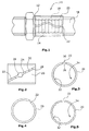
- Fig. 1 shows a clamping fitting 10 in the assembled state.
- the clamping fitting 10 has a fitting body 12, which is provided with a support sleeve 14.
- This support sleeve 14 may be profiled on its outer side and / or have a sealing element (eg O-ring).
- On the support sleeve the end 16 of a pipe 18 to be connected is pushed.
- This connection end 16 in turn is enclosed by a slotted clamping sleeve 20, which in this exemplary embodiment has a wave-shaped slot 22.
- the clamping sleeves 20 was pushed in the expanded state to the terminal end 16 of the tube 18, for which purpose a spacer 24 was inserted into the slot 22 of the clamping sleeve 20, as for example in the FIGS. 6 to 17 is shown.
- Fig. 2 shows a further embodiment of the clamping sleeve 20 with obliquely extending slot 22 and arranged in this spacer 24, which has a shape which is formed according to a widening 26 in the slot 22.
- the slot 22 is formed by flanks 28,30 of the wall of the clamping sleeve 20.
- the spacer 24 abuts the flanks 28,30 and keeps them at a distance, ie the clamping sleeve 20 in the expanded state.
- FIGS. 3 to 5 show various embodiments of the slot 22.
- the slot 22 in the clamping sleeve 20 of Fig. 3 essentially aligned radially and has substantially mutually parallel flanks 28,30.
- the slot 22 extends at an angle to the radial extent of the clamping sleeve 20.
- the slot 22 is widened outwards.
- the show FIGS. 3 and 4 different surface contours 32 on the inner side 34 of the clamping sleeve 20. In this way, increased safety of the clamping sleeve 20 against axial displacements relative to the terminal end 16 of the tube 18 can be achieved.
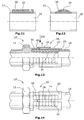
- FIGS. 6 to 10 different spacers 24 are shown for maintaining the expansion of the clamping sleeve 20.
- the spacer 24 is shown with a rectangular cross-section.
- Fig. 7 10 shows a round-outline spacer 24 and a handle 36 for gripping the spacer 24 by means of a tool to remove the spacer 24 from the slot 22.
- Fig. 8 shows a spacer 24 with wedge-shaped portion 38 whose wedge shape is adapted to the wedge shape of the slot 22.
- the spacers 24 each have spring properties.
- FIGS. 11 and 12 For example, two collets 20 are shown with spacers 24 disposed in their slots 22 which have recesses 36 in the form of cutouts in this embodiment which allow tools to be used to pull the spacers 24 out of the slots 22.
- FIGS. 13 and 14 an embodiment of a clamping fitting 10 'is shown, in which the spacer 24 of the clamping sleeve 20 is automatically removed when the clamping sleeve 20 is pushed over the terminal end 16 of the tube 18 and the support sleeve 14.
- a Auswerfervorsprung 39 is formed on the fitting body 12, against which an inclined surface 40 of the spacer 24 abuts when the clamping sleeve 20 is pushed in the direction of Aufwerfervorsprungs 39.
- Fig. 14 shows the situation or the construction of this clamp fitting 10 'in the direction of arrow 14 of Fig. 13 ,
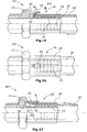
- FIGS. 15 and 16 there is described a clamp fitting 10 "not in accordance with the invention in which the spacer 24 is ejected from the pipe 18 when the pipe 18 is near its maximum insertion position, the spacer 24 having a trigger portion 42 which is inserted into the annular space 44 the ferrule 20 and the support sleeve 14.
- the end face 46 of the terminal end 16 of the tube 18 then presses against the release portion 42 of the spacer 24, which thus "out” out of the slot of the sleeve 20 outwards.
- Fig. 17 shows a not belonging to the invention clamping fitting 10, wherein the clamping sleeve 20 is held in the expanded state on the fitting body 12.
- the fitting body 12 has a ring recess 48 which is open towards the free end of the support sleeve 14 and the clamping sleeve 20 surrounds by clamping.
- the spacer 24 In the slot of the clamping sleeve 20 is the spacer 24, which has a rounding 50 on its underside facing the support sleeve 14. In this rounding, the spacer 24 protrudes into the annular space 44 between the clamping sleeve 20 and the support sleeve 14.
- the front side 46 of the tube 18 now presses when inserting the tube from below over the rounding 50 against the spacer 24, so that it turns out of the slot to the outside, the clamping sleeve 20 thus releases and the clamping sleeve 20 thus their clamping force on the terminal end 16th of the tube 18 can exercise.
Abstract
Description
Die Erfindung betrifft einen Klemmfitting für ein Rohr und insbesondere einen Klemmfitting für ein Kunststoffrohr oder Kunststoff-Metall-Verbundrohr.The invention relates to a clamping fitting for a pipe and in particular a clamping fitting for a plastic pipe or plastic-metal composite pipe.
Derartige Klemmfittinge sind im Stand der Technik hinlänglich bekannt und weisen einen Fittingkörper auf, der mit einer Stützhülse versehen ist, auf die das Ende eines anzuschließenden Rohres aufschiebbar ist. Außen um das auf die Stützhülse aufgeschobene Anschlussende des Rohres befindet sich eine Hülse, die mit Hilfe eines Presswerkzeuges radial gestaucht wird und damit das Anschlussende des Rohres in die Stützhülse presst, wodurch einerseits die erforderliche Dichtigkeit und andererseits eine Zugentlastung gegeben ist.Such clamping fittings are well known in the art and have a fitting body which is provided with a support sleeve on which the end of a pipe to be connected can be pushed. Outside of the pushed onto the support sleeve connection end of the tube is a sleeve which is radially compressed by means of a pressing tool and thus presses the terminal end of the tube in the support sleeve, which on the one hand the required tightness and on the other hand, a strain relief is given.
Diese Pressfittingtechnik hat sich in der Praxis bewährt und wird insbesondere für den Anschluss von Kunststoffrohren oder Kunststoff-Metall-Verbundrohren eingesetzt.This Pressfittingtechnik has proven itself in practice and is used in particular for the connection of plastic pipes or plastic-metal composite pipes.
Zur Vermeidung der Verwendung von Presswerkzeugen wurde bereits in der Vergangenheit vorgeschlagen, anstelle einer Presshülse eine Klemm- bzw. Spannhülse zu verwenden. Dies ist in
Ferner ist aus
Aufgabe der Erfindung ist es, einen Klemmfitting für ein Rohr, insbesondere Kunststoffrohr oder Kunststoff-Metall-Verbundrohr zu schaffen, bei dem die auf das anzuschließende Rohr wirkende Andrückkraft ohne Verwendung eines Presswerkzeuges aufgebracht wird und bei dem die Montage der Klemmhülse vereinfacht ist.The object of the invention is to provide a clamping fitting for a pipe, in particular plastic pipe or plastic-metal composite pipe, in which the force acting on the pipe to be connected pressing force is applied without the use of a pressing tool and in which the mounting of the clamping sleeve is simplified.
Zur Lösung dieser Aufgabe wird mit der Erfindung ein Klemmfitting für ein Rohr, insbesondere Kunststoffrohr oder Kunststoff-Metall-Verbundrohr vorgeschlagen, der versehen ist mit
- einem Fittingkörper, der eine Stützhülse aufweist, auf die ein Ende eines anzuschließenden Rohres aufschiebbar ist, und
- einer eine Wandung aufweisenden Klemmhülse, die einen zwischen ihren axialen Enden verlaufenden, von gegenüberliegenden Flanken der Wandung begrenzten Schlitz aufweist und aufweitbar ist, wobei die Klemmhülse die Stützhülse und das Ende des anzuschließenden Rohres im auf die Stützhülse aufgeschobenen Zustand umgibt.
- a fitting body having a support sleeve on which one end of a pipe to be connected is pushed, and
- a clamping sleeve having a wall, which has a slot extending between its axial ends and being delimited by opposite flanks of the wall, the clamping sleeve surrounding the supporting sleeve and the end of the pipe to be connected in the state pushed onto the supporting sleeve.
Bei diesem Klemmfitting ist vorgesehen, dass zur Beibehaltung des aufgeweiteten Zustandes der Klemmhülse in deren Schlitz ein entfernbarer Abstandshalter angeordnet ist, gegen den sich die den Schlitz begrenzenden Flanken der Wandung der aufgeweiteten Klemmhülse abstützenIn this clamping fitting it is provided that in order to maintain the expanded state of the clamping sleeve in the slot a removable Spacer is arranged against which support the slot defining flanks of the wall of the expanded clamping sleeve
Der erfindungsgemäße Klemmfitting umfasst eine Spann- oder Klemmhülse, die mindestens einen Schlitz aufweist, der sich zwischen den axialen Enden der Klemmhülse erstreckt. Infolge des Schlitzes kann die Klemmhülse, die im Regelfall aus Metall besteht bzw. Metall aufweist, aufgeweitet werden, wobei sich die Klemmhülse elastisch verformt und eine Rückstellkraft erzeugt, die dann, wenn die Klemmhülse das auf die Stützhülse des Fittingkörpers aufgeschobene Anschlussende des Rohres umgibt, zum Andrücken des Anschlussendes des Rohres gegen die Stützhülse genutzt wird. Hierbei übernimmt also die Klemmhülse sozusagen die Aufgabe des Presswerkzeuges bzw. die Presshülse übernimmt die Funktion des Presswerkzeuges.The inventive clamping fitting comprises a tensioning or clamping sleeve which has at least one slot extending between the axial ends of the clamping sleeve. As a result of the slot, the clamping sleeve, which usually consists of metal or metal, be widened, wherein the clamping sleeve elastically deformed and generates a restoring force, the then, when the clamping sleeve surrounds the pushed onto the support sleeve of the fitting body connection end of the tube, is used for pressing the connection end of the tube against the support sleeve. In this case, therefore, the clamping sleeve takes over, so to speak, the task of the pressing tool or the compression sleeve assumes the function of the pressing tool.
Es ist vorgesehen, dass die Klemmhulse durch Anordnung eines Abstandshalters in dem Schlitz in ihrem aufgeweiteten Zustand gehalten wird, wobei die den Schlitz begrenzenden Flanken der Wandung der aufgeweiteten Stützhülse an dem Abstandshalter anliegen. Der Abstandshalter vereinfacht die Handhabung und Montage der Klemmhülse ganz entscheidend, da die Klemmhülse, ohne von einem Aufspreizwerkzeug manipuliert zu sein, selbsttätig in ihrem aufgeweiteten Zustand verbleibt. Der Abstandshalter kann werkseitig in den Schlitz der Klemmhülse eingebracht sein oder aber wird vor der Montage der Klemmhülse vom Monteur in den Schlitz verbracht.It is envisaged that the clamping sleeve is held in its expanded state by the provision of a spacer in the slot, with the flanks of the wall of the flared supporting sleeve delimiting the slot abutting the spacer. The spacer greatly simplifies handling and assembly of the collet as the collet automatically remains in its expanded state without being manipulated by a spreading tool. The spacer may be factory introduced into the slot of the collet or spent before assembly of the collet by the installer in the slot.
Der Abstandshalter kann zweckmäßigerweise mittels eines Werkzeuges aus dem Schlitz der Klemmhülse entfernt werden, um die Klemmhülse "freizugeben". Alternativ ist es möglich, dass der Abstandshalter ein Handhabungsorgan zum manuellen Entfernen des Abstandshalters aus dem Schlitz der Klemmhülse aufweist. Ein geeignetes Handhabungsorgan ist beispielsweise ein Ringelement, das mit dem Abstandshalter verbunden ist oder integral am Abstandshalter ausgebildet ist. Andere Anfassorgane wie beispielsweise Hakenelemente o.dgl. können ebenfalls am Abstandshalter vorgesehen sein, um diesen manuell aus dem Schlitz der Klemmhülse entfernen zu können.The spacer can be conveniently removed by means of a tool from the slot of the clamping sleeve to "release" the clamping sleeve. Alternatively, it is possible that the spacer has a handling member for manually removing the spacer from the slot of the clamping sleeve. A suitable handling member is, for example, a ring member which is connected to the spacer or integrally formed on the spacer. Other Grasping organs such as hook elements or the like. may also be provided on the spacer to remove it manually from the slot of the clamping sleeve can.
Anstelle einer manuellen Entfernung des Abstandshalters oder einer Entfernung durch ein Werkzeug ist es auch möglich, dass der Abstandshalter automatisch bei der Montage der Klemmhülse bzw. beim Anschließen des Rohres aus dem Schlitz entfernt wird. Hierzu ist bei einer ersten Variante der Erfindung vorgesehen, dass der Fittingkörper ein Auswerferelement aufweist, gegen und/oder über das der Abstandshalter beim Aufschieben der aufgeweiteten Klemmhülse über das auf der Stützhülse befindliche Ende des anzuschließenden Rohres zum Herausbewegen des Abstandshalters aus dem Schlitz bewegbar ist. Bei dieser Variante weist der Fittingkörper ein Auswerferelement auf, gegen das der Abstandshalter beim Aufschieben der aufgeweiteten Hülse läuft und von dem Auswerferelement in im wesentlichen radialer Richtung der Klemmhülse ausgelenkt und damit "ausgeworfen" wird.Instead of a manual removal of the spacer or a removal by a tool, it is also possible that the spacer is removed automatically during the assembly of the clamping sleeve or when connecting the tube from the slot. For this purpose, in a first variant of the invention, it is provided that the fitting body has an ejector element, against and / or over the spacer when sliding the expanded clamping sleeve over the end of the end piece to be connected Pipe for moving out of the spacer from the slot is movable. In this variant, the fitting body has an ejector element, against which the spacer runs when the expanded sleeve is slid on and is deflected by the ejector element in a substantially radial direction of the clamping sleeve and thus "ejected".
Bei einer nicht zur Erfindung gehörenden Variante zum automatischen Entfernen des Abstandshalters aus dem Schlitz der Klemmhülse bei der Montage des Fittings ist vorgesehen, dass der Abstandshalter einen die Wandung der Klemmhülse über deren Innenseite überragenden Auslöseabschnitt aufweist und dass das Ende des anzuschließenden Rohres beim Aufschieben auf die Stützhülse und bei diese umgebender Klemmhülse zum Herausbewegen des Abstandshalters aus dem Schlitz der Klemmhülse gegen den Auslöseabschnitt des Abstandshalters bewegbar ist. Hierbei kann die Klemmhülse im aufgeweiteten Zustand am Fittingkörper vormontiert sein. Wird dann das anzuschließende Rohrende in den Bereich zwischen der Klemmhülse unter der Stützhülse geschoben, kommt es in Kontakt mit dem Auslöseabschnitt des Abstandshalters, da dieser Auslöseabschnitt in den Ringraum zwischen der Klemmhülse und der Stützhülse hineinragt, und zwar am Ende dieses Ringraums, in das das anzuschließende Rohrende hineinbewegt wird, kurz bevor es vollständig in den Ringraum eingeschoben ist.In a not belonging to the invention variant for automatically removing the spacer from the slot of the clamping sleeve during assembly of the fitting is provided that the spacer has a wall of the clamping sleeve on the inside superior triggering section and that the end of the pipe to be connected when pushed onto the Support sleeve and in this surrounding clamping sleeve for moving out of the spacer from the slot of the clamping sleeve against the release portion of the spacer is movable. In this case, the clamping sleeve can be preassembled in the expanded state on the fitting body. If then the pipe end to be connected is pushed into the region between the clamping sleeve under the support sleeve, it comes into contact with the release portion of the spacer, since this triggering portion protrudes into the annular space between the clamping sleeve and the support sleeve, at the end of this annulus, in which to be connected pipe end is moved into, just before it is fully inserted into the annulus.
Zur Verbesserung des Halts der Klemmhülse auf dem Anschlussende des Rohres kann die Innenseite der Klemmhülse strukturiert sein, was beispielsweise durch ein Sägezahnprofil, Noppen oder eine aufgeraute Oberfläche realisiert werden kann.To improve the hold of the clamping sleeve on the connecting end of the tube, the inside of the clamping sleeve can be structured, which can be realized for example by a sawtooth profile, knobs or a roughened surface.
Die Klemmhülse weist zweckmäßigerweise einen Werkstoff auf bzw. die Dicke ihrer Wandung ist derart gewählt, dass nach Aufhebung einer elastischen Aufweitung der Klemmhülse diese das Ende des anzuschließenden Rohres dichtend und zugentlastend gegen die Stützhülse drückt. Als Material eignen sich z.B. Metalle und Metalllegierungen. Insbesondere kommen sogenannte superplastische Materialien (insbesondere metallische Materialien) wie z.B. Formgedächtnislegierungen in Frage. Ein Beispiel für eine superplastische Legierung ist eine NiTi-Legierung, wie z.B. Nitinol. Superplastische metallische Materialien zeichnen sich durch eine Kraft-Weg-Kennlinie mit einem Plateau aus, das einen Kraftverlauf beschreibt, bei dem die Kraft über einen Teilbereich des Weges im wesentlichen konstant bleibt.The clamping sleeve expediently has a material or the thickness of its wall is chosen such that, after the elastic sleeve has been widened, it presses the end of the pipe to be connected in a sealing and tensile-relieving manner against the support sleeve. Suitable materials include, for example, metals and metal alloys. In particular, so-called superplastic materials (in particular metallic materials) such as, for example, shape memory alloys are used in question. An example of a superplastic alloy is a NiTi alloy such as nitinol. Superplastic metallic materials are characterized by a force-displacement characteristic with a plateau, which describes a course of force in which the force remains essentially constant over a portion of the path.
Für die Handhabung des erfindungsgemäßen Klemmfittings ist es ferner zweckmäßig, wenn die Klemmhülse im aufgeweiteten Zustand an dem Fittingkörper gehalten ist, und zwar unter Ermöglichung einer Kontraktion bei entferntem Abstandshalter.For the handling of the clamp fitting according to the invention, it is also useful if the clamping sleeve is held in the expanded state of the fitting body, while allowing a contraction with removed spacer.
Der Abstandshalter kann darüber hinaus auch der Verpresskennzeichnung des Klemmfittings dienen. Sobald nämlich der Abstandshalter nicht mehr vorhanden ist, drückt die Klemmhülse das anzuschließende Rohrende dichtend und zugentlastend gegen die Stützhülse. Der (Klemm-)Fitting ist also "verpresst". Der Abstandshalter sollte also aus der Entfernung gut erkennbar sein, so dass man dann, wenn man keinen Abstandshalter erkennt, auch zuverlässig davon ausgehen kann, dass die Klemmhülse freigegeben ist, also klemmend auf dem anzuschließenden Rohrende sitzt und dieses gegen die Stützhülse drückt.The spacer can also serve the Verpresskennzeichnung the compression fitting beyond. Namely, as soon as the spacer is no longer available, the clamping sleeve presses the pipe to be connected sealingly and zugentlastend against the support sleeve. The (clamping) fitting is so "pressed". The spacer should therefore be easily recognizable from a distance, so that if you do not recognize a spacer, you can reliably assume that the clamping sleeve is released, so sitting clamped on the pipe end to be connected and presses against the support sleeve.
Die Klemmhülse weist im Regelfall eine im wesentlichen zentrische, elliptische oder andere ringartige Struktur auf.As a rule, the clamping sleeve has a substantially centric, elliptical or other ring-like structure.
Die Anpressung des Rohrendes durch die Presshülse sollte in jeder Radialebene der Stützhülse über 360° erfolgen. Innerhalb des Schlitzes erfolgt jedoch keine oder nur eine geringe Anpressung, insbesondere wenn es zu einer Quetschung des Materials des Rohres kommt. Von Vorteil ist es insoweit, wenn der Schlitz einen wellen- bzw. sinusförmigen Verlauf entlang der Axialerstreckung der Presshülse aufweist. Damit sind die Umfangsbereiche des Rohrendes, in denen dieses wegen des im verpressten Zustand offenen Schlitzes weniger stark gegen die Stützhülse gedrückt ist, in benachbarten Radialebenen längs der Axialerstreckung der Presshülse in Umfangsrichtung versetzt zueinander angeordnet.The pressure of the pipe end by the compression sleeve should be done in each radial plane of the support sleeve over 360 °. Within the slot, however, no or only a small contact pressure, especially if it comes to a pinching of the material of the tube. It is advantageous insofar as the slot has a wave or sinusoidal course along the axial extension of the compression sleeve. Thus, the peripheral portions of the pipe end, in which this is less strongly pressed against the support sleeve because of the open in the compressed state slot, offset in adjacent radial planes along the axial extension of the compression sleeve in the circumferential direction to each other.
Die Besonderheiten des erfindungsgemäßen Klemmfittings werden nachfolgend nochmals wie folgt wiedergegeben.The peculiarities of the clamp fitting according to the invention are reproduced again below as follows.
Die Klemmhülse des Klemmfittings ist selbstverriegelnd und übernimmt die Funktion, die eine Presshülse nach ihrer Verpressung hat.
- 1. Die Klemmhülse wird im einfachsten Fall als Rohrkörper hergestellt. In der einfachsten Ausführung weist die Klemmhülse einen zentrischen oder elliptischen Querschnitt auf. Die Innengeometrie der Klemmhülse ist entsprechend dem Außendurchmesser des anzuschließenden Rohres zu wählen. Im aufgeweiteten Zustand kann eine Spielpassung oder aber auch eine Übergangspassung zum anzuschließenden Rohr bestehen. Nach Aufhebung der auf dem Anschlussende des Rohres sitzenden Klemmhülse sollte deren Schlitz nicht vollständig geschlossen sein, da dies die Andrückkraft der Klemmhülse gegen das anzuschließende Rohrende begrenzt. Das Innenprofil der Klemmhülse kann sowohl glatt als auch mit Konturen (beispielsweise Sägezahnprofil, Noppen) und/oder mit aufgerauter Oberfläche versehen sein.
- 2. Die axiale Länge der Klemmhülse sollte entsprechend den Längen heutiger üblicher Presshülsen gewählt werden.
- 3. Die Dicke der Wandung ist ebenfalls abhängig vom Werkstoff und der erforderlichen Andrückkraft geeignet zu wählen.
- 4. Der Werkstoff der Klemmhülse (vorzugsweise Metall) ist zweckmäßigerweise hinreichend korrosionsbeständig und/oder beschichtet.
- 5. Die Klemmhülse des erfindungsgemäßen Klemmfittings ist mindestens einmal axial unter einem Winkel zwischen 0° und 85° zur Längsachse geschlitzt. Die Schlitzung kann auch als Gewinde/Wendelnut mit im wesentlichen beliebiger Steigung und sowohl ein- als auch mehrgängig erfolgen. Hierbei kann die Klemmhülsenwandung ganz und/oder teilweise durchdrungen sein. Die Durchdringung erfolgt innerhalb eines Winkelbereichs zwischen 90° zur Klemmhülsenoberfläche (parallel zur Längsachse) und einem Grenzwinkel > 0°, der bei gegebenem Rohrkörper noch zur Erzeugung einer brauchbaren Kontur führt. Die Kontur der Durchdringung (Schlitzung) in radialer Richtung kann mit beliebigen Böschungs- bzw. Flankenwinkeln ausgeführt sein. Bei einer vorteilhaften Ausführung kann der Flankenwinkel im Bereich der Selbsthemmung von Teilen liegen, wobei die geneigten Flankenwinkel derart gewählt sind, dass sich die Breite des Schlitzes von der Innen- zur Außenseite der Klemmhülse hin vergrößert. Die Kontur der Durchdringung (Schlitzung) in axialer Richtung kann von gleichbleibender Breite (einfachster Fall wäre ein gerader Schlitz) bis zu beliebig strukturierten Ausführungen (beispielsweise gewellt mit und ohne Hinterschnitt) in Umfangsrichtung reichen. Bei alldem ist zu beachten, dass sich infolge der Erstreckung und Ausrichtung des Schlitzes eine Klemmhülse ergibt, die in radialer Richtung über eine größere Elastizität als in axialer Richtung verfügt, in axialer Richtung also eine größere Steifigkeit als in radialer Richtung aufweist.
- 6. Die zuvor beschriebene Klemmhülse wird mit Hilfe des Abstandshalters im radial aufgeweiteten Zustand gehalten.
- 7. Beispiele für Abstandshalter sind ein Metallprisma (Teilleisten o.dgl.) oder aber auch Elemente mit und ohne Eigenfederung. Es sind ferner als Abstandshalter Elemente mit Radien denkbar, beispielsweise runde oder rohrförmige Elemente. Die Länge des Abstandshalters ist grundsätzlich beliebig, sollte aber nicht größer als die Schlitzlänge sein. Der Abstandshalter und die weiter oben beschriebenen Ausführungsformen der Schlitzkontur bilden eine funktionale Einheit mit dem Ziel der Funktionssicherheit.
- 8. Die Einheit aus Klemmhülse und Abstandshalter kann beispielsweise mittels eines Zwischenstücks (Haltering o.dgl.) am Fittingkörper befestigt sein. Beispielsweise könnte es sich hierbei um einen Kunststoffring handeln, der einerseits an dem Fittingkörper befestigt ist und andererseits die aufgeweitete Klemmhülse aufnimmt, also außen an der Klemmhülse angreift. Hier können noch Aussparungen zur Kontrolle der Rohreinschubtiefe vorgesehen sein. Dadurch kann der Fittingkörper einschließlich der Stützhülse einfacher gestaltet sein.
- 9. Es ist ebenfalls möglich, den Fittingkörper und die Klemmhülse getrennt, also nicht vormontiert, zu liefern.
- 10. Zur Montage wird das anzuschließende Rohrende (bei am Fittingkörper vormontierter aufgeweiteter Klemmhülse) in den Ringraum zwischen der Stützhülse und der Klemmhülse eingeführt. Nach Erreichen der erforderlichen Einschubtiefe des Rohres wird mittels eines Werkzeuges oder manuell der Abstandshalter aus dem Schlitz der Hülse nach außen herausgezogen. Dadurch federt die Klemmhülse zurück und presst das Rohr gegen die Stützhülse. Die Verpresskraft reicht dabei aus, um sowohl eine Fluidabdichtung als auch eine Abzugssicherheit zu erreichen.
- 11. Das Konzept des Klemmfittings bringt eine integrierte "Verpresskennzeichnung" mit sich. Fehlt der Abstandshalter, ist die Verbindung "verpresst".
- 12. Alternativ zu der Entfernung des Abstandshalters durch manuellen Eingriff oder durch Verwendung eines Werkzeuges ist es auch möglich, die Montage werkzeuglos durchzuführen. Hierbei kann der Abstandshalter beim Einschieben des anzuschließenden Rohrendes von diesem ausgeworfen werden. Erreicht werden kann dies beispielsweise durch eine Ausbildung des Abstandshalter in demjenigen Bereich, in dem er von dem Rohr kontaktiert wird. In diesem Bereich kann der Abstandshalter Radien oder Schrägen aufweisen. Die Rohrstirnseite des eingeschobenen Rohres läuft gegen diese Radien oder Schrägen, wodurch der Abstandshalter angehoben und "ausgeworfen" wird. Vorteilhaft zur Erreichen dieses Effekts ist eine getrennte Bereitstellung der Klemmhülse. Die Montage erfolgt dann durch Aufschieben der Klemmhülse auf das anzuschließende Rohrende, woraufhin beide zusammen auf die Stützhülse bzw. über die Stützhülse geschoben werden. Am Fittingkörper kann nun eine entsprechende Gegenkontur vorgesehen sein, die als Anschlag für den Abstandshalter dient, wenn das Rohrende und die Klemmhülse aufgeschoben werden. Beim Auflaufen des Abstandshalters gegen diesen Anschlag wird der Abstandshalter angehoben und dadurch aus dem Schlitz bewegt.
- 1. The clamping sleeve is made in the simplest case as a tubular body. In the simplest embodiment, the clamping sleeve has a central or elliptical cross section. The internal geometry of the clamping sleeve should be selected according to the outside diameter of the pipe to be connected. In the expanded state may be a clearance or even a transition fit to be connected pipe. After removing the seated on the connecting end of the tube clamping sleeve whose slot should not be completely closed, as this limits the pressure force of the clamping sleeve against the pipe end to be connected. The inner profile of the clamping sleeve can be both smooth and with contours (for example sawtooth profile, knobs) and / or provided with roughened surface.
- 2. The axial length of the clamping sleeve should be selected according to the lengths of today's conventional press sleeves.
- 3. The thickness of the wall is also suitable depending on the material and the required pressing force to choose.
- 4. The material of the clamping sleeve (preferably metal) is suitably sufficiently corrosion resistant and / or coated.
- 5. The clamping sleeve of the clamping fitting according to the invention is slotted at least once axially at an angle between 0 ° and 85 ° to the longitudinal axis. The slotting can also be done as a thread / helical groove with substantially any slope and both single and multi-speed. Here, the clamping sleeve wall completely and / or partially penetrated be. The penetration occurs within an angle range between 90 ° to the clamping sleeve surface (parallel to the longitudinal axis) and a critical angle> 0 °, which still leads to the production of a usable contour at a given tubular body. The contour of the penetration (slit) in the radial direction can be designed with any slope or flank angles. In an advantageous embodiment, the flank angle can be in the range of self-locking of parts, wherein the inclined flank angles are selected such that the width of the slot increases from the inside to the outside of the clamping sleeve. The contour of the penetration (slit) in the axial direction can range from constant width (simplest case would be a straight slot) to arbitrarily structured designs (for example, corrugated with and without undercut) in the circumferential direction. In all this, it should be noted that, as a result of the extension and alignment of the slot, a clamping sleeve results, which has a greater elasticity in the radial direction than in the axial direction, that is, has a greater rigidity in the axial direction than in the radial direction.
- 6. The clamping sleeve described above is held by means of the spacer in the radially expanded state.
- 7. Examples of spacers are a metal prism (partial strips or the like.) Or else elements with and without inherent resilience. There are also conceivable as spacers elements with radii, such as round or tubular elements. The length of the spacer is basically arbitrary, but should not be greater than the slot length. The spacer and the above-described embodiments of the slot contour form a functional unit with the goal of functional reliability.
- 8. The unit of clamping sleeve and spacer can be fixed, for example by means of an intermediate piece (retaining ring or the like.) On the fitting body. For example, this could be a plastic ring, on the one hand is attached to the fitting body and on the other hand receives the expanded clamping sleeve, that engages outside of the clamping sleeve. Here can still be provided recesses for controlling the pipe insertion depth. Thereby, the fitting body including the support sleeve can be made simpler.
- 9. It is also possible to deliver the fitting body and the clamping sleeve separately, that is not preassembled.
- 10. For installation, the pipe end to be connected is inserted (in the case of a widened clamping sleeve preassembled on the fitting body) into the annular space between the support sleeve and the clamping sleeve. After reaching the required insertion depth of the tube, the spacer is pulled out of the slot of the sleeve to the outside by means of a tool or manually. As a result, the clamping sleeve springs back and presses the tube against the support sleeve. The pressing force is sufficient to achieve both a fluid seal and a trigger safety.
- 11. The concept of the compression fitting implies an integrated "Verpresskennzeichnung" with it. If the spacer is missing, the connection is "compressed".
- 12. As an alternative to the removal of the spacer by manual intervention or by using a tool, it is also possible to perform the assembly without tools. In this case, the spacer can be ejected during insertion of the pipe end to be connected from this. This can be achieved, for example, by forming the spacer in the region in which it is contacted by the pipe. In this area, the spacer may have radii or bevels. The tube end face of the inserted tube runs against these radii or bevels, whereby the spacer is lifted and "ejected". Advantageous for achieving this effect is a separate provision of the clamping sleeve. The assembly then takes place by sliding the clamping sleeve onto the pipe end to be connected, whereupon both are pushed together onto the supporting sleeve or over the supporting sleeve. On the fitting body, a corresponding counter contour can now be provided, which serves as a stop for the spacer when the pipe end and the clamping sleeve are pushed. Upon emergence of the spacer against this stop the spacer is lifted and thereby moved out of the slot.
Die Erfindung wird nachfolgend anhand verschiedener Ausführungsbeispiele und unter Bezugnahme auf die Zeichnung näher erläutert. Im einzelnen zeigen dabei:
- Fig. 1
- eine Seitenansicht auf ein einen Klemmfitting mit klemmend auf dem anzuschließenden Rohrende sitzender Klemmhülse,
- Fig. 2
- eine Variante einer Klemmhülse mit schräg zur Längsachse verlaufender Schlitzung,
- Fign. 3 bis 5
- Querschnitte durch verschiedene Klemmhülsen zur Verdeutlichung unterschiedlich ausgerichteter und gestalteter Schlitzungen sowie unterschiedlich strukturierter Innenflächen der Klemmhülse,
- Fign. 6
bis 10 - Querschnitte weiterer Ausführungsbeispiele von Klemmhülsen zur Darstellung der unterschiedlichen Formen möglicher Abstandshalter zur Aufrechthaltung des aufgeweiteten Zustandes der Klemmhülse,
- Fign. 11 und 12
- Längsschnitte durch von Abstandshaltern im aufgeweiteten Zustand gehaltenen, geschlitzten Klemmhülsen, wobei die Abstandshalter mit Hilfe von Werkzeugen aus den Schlitzen entfernbar sind,
- Fign. 13 und 14
- Halbschnitte bzw. Seitenansichten eines weiteren Ausführungsbeispiels eines Klemmfittings mit bei der Montage selbsttätig entfernbarem Abstandshalter,
- Fign. 15 und 16
- einen Klemmfitting im Längsschnitt und in Seitenansicht, wobei der Abstandshalter beim Einschieben des Rohres selbsttätig ausgeworfen wird, und
- Fig. 17
- einen Klemmfitting im Längsschnitt mit beim Einschieben des Rohres automatisch aus dem Schlitz der Klemmhülse sich herausbewegendem Abstandshalter.
- Fig. 1
- a side view of a clamping fitting sitting with a clamping on the pipe to be connected clamping sleeve,
- Fig. 2
- a variant of a clamping sleeve with obliquely to the longitudinal axis slit,
- FIGS. 3 to 5
- Cross sections through different clamping sleeves to illustrate differently aligned and designed slits and differently structured inner surfaces of the clamping sleeve,
- FIGS. 6 to 10
- Cross sections of further embodiments of clamping sleeves to illustrate the different forms of possible spacers for maintaining the expanded state of the clamping sleeve,
- FIGS. 11 and 12
- Longitudinal sections through spacers in the expanded state held, slotted clamping sleeves, the spacers are removed by means of tools from the slots,
- FIGS. 13 and 14
- Half sections or side views of a further embodiment of a compression fitting with automatically removable during assembly spacer,
- FIGS. 15 and 16
- a clamping fitting in longitudinal section and in side view, wherein the spacer is automatically ejected during insertion of the tube, and
- Fig. 17
- a Klemmfitting in longitudinal section with the insertion of the tube automatically from the slot of the clamping sleeve herausbewegendem spacer.
In der Zeichnung sind eine Vielzahl von unterschiedlichen Ausführungsformen des Klemmfittings bzw. der Klemmhülse und des Abstandshalters gezeigt. Soweit die in den einzelnen Figuren gezeigten Bestandteile des Klemmfittings funktional oder konstruktiv gleich sind, sind sie mit dem gleichen Bezugszeichen versehen.In the drawing, a plurality of different embodiments of the clamping fitting and the clamping sleeve and the spacer are shown. As far as the components of the clamping fitting shown in the individual figures are functionally or structurally the same, they are provided with the same reference numerals.
In den
In den
In den
In den
Claims (11)
- A clamp fitting for a tube, in particular a plastic tube or a plastic/metal composite tube, comprising- a fitting body (12) comprising a supporting sleeve (14) over which an end (16) of a tube (18) to be connected can be slipped, and- an expandable clamping sleeve (20) comprising a wall, said clamping sleeve comprising a slit (22) extending between its axial ends and limited by opposite flanks (28, 30) of the wall, wherein the clamping sleeve (20) surrounds the supporting sleeve (14) and the end (16) of the tube (18) to be connected when slipped over the supporting sleeve,- a removable spacer (24) being arranged in the slit (22) of the clamping sleeve (20) in order to maintain it in the expanded state, the flanks (28, 30) of the wall of the expanded clamping sleeve (20), which limit the slit (22), resting against the spacer (24),
characterized in that- the fitting body (12) comprises an ejector element (39) against and/or over which the spacer (24) can be moved when the expanded clamping sleeve (20) is slipped over the end (16) of the tube (18) to be connected situated on the supporting sleeve (14) for moving the spacer (24) out of the slit (22). - A clamp fitting for a tube, in particular a plastic tube or a plastic/metal composite tube, comprising- a fitting body (12) comprising a supporting sleeve (14) over which an end (16) of a tube (18) to be connected can be slipped, and- an expandable clamping sleeve (20) comprising a wall, said clamping sleeve comprising a slit (22) extending between its axial ends and limited by opposite flanks (28, 30) of the wall, wherein the clamping sleeve (20) surrounds the supporting sleeve (14) and the end (16) of the tube (18) to be connected when slipped over the supporting sleeve,- a removable spacer (24) being arranged in the slit (22) of the clamping sleeve (20) in order to maintain it in the expanded state, the flanks (28, 30) of the wall of the expanded clamping sleeve (20), which limit the slit (22), resting against the spacer (24),
characterized in that- the spacer (24) comprises manipulation elements (36) in the form of recesses which allow positioning of a tool for pulling the spacer (24) out of the slit (22) of the clamping sleeve (20). - The clamp fitting according to any of the claims 1 or 2, characterized in that the slit (22) has a wave-shaped or sinusoidal profile along the axial extension of the clamping sleeve (20).
- The clamp fitting according to any of the claims 1 or 2, characterized in that the slit (22) is realized as a thread/helical groove.
- The clamp fitting according to any of the claims 1 to 3, characterized in that the clamping sleeve (20) has a structured inner side (34).
- The clamp fitting according to any of the claims 1 to 4, characterized in that the clamping sleeve (20) comprises a material and/or the wall of the clamping sleeve (20) has a thickness selected such that upon termination of an elastic expansion of the clamping sleeve (20) the latter presses the end (16) of the tube (18) to be connected against the supporting sleeve (14) in a sealing and strain-relieving manner.
- The clamp fitting according to any of the claims 1 to 6, characterized in that the clamping sleeve (20) is retained on the fitting body (12) in the expanded state enabling a contraction when the spacer (24) is removed.
- The clamp fitting according to any of the claims 1 to 7, characterized in that the spacer (24) comprises a pressing operation marking portion which is arranged outside the wall of the clamping sleeve (20).
- The clamp fitting according to any of the claims 1 to 8, characterized in that the clamping sleeve (20) has an essentially cylindrical, elliptic or other ring-like structure.
- The clamp fitting according to any of the claims 1 to 9, characterized in that a contour of the slit (22) is realized with a flank angle in such a manner that a width of the slit increases from an inner side to the outer side of the clamping sleeve.
- The clamp fitting according to any of the claims 1 to 10, characterized in that the material of the clamping sleeve comprises a superplastic material, in particular a shape memory alloy.
Applications Claiming Priority (2)
| Application Number | Priority Date | Filing Date | Title |
|---|---|---|---|
| DE102007025931A DE102007025931B3 (en) | 2007-06-02 | 2007-06-02 | Clamp fitting for a pipe |
| PCT/EP2008/056758 WO2008148728A1 (en) | 2007-06-02 | 2008-06-02 | Clamping fitting for a pipe |
Publications (2)
| Publication Number | Publication Date |
|---|---|
| EP2150743A1 EP2150743A1 (en) | 2010-02-10 |
| EP2150743B1 true EP2150743B1 (en) | 2012-06-13 |
Family
ID=39869795
Family Applications (1)
| Application Number | Title | Priority Date | Filing Date |
|---|---|---|---|
| EP08760345A Active EP2150743B1 (en) | 2007-06-02 | 2008-06-02 | Clamping fitting for a pipe |
Country Status (5)
| Country | Link |
|---|---|
| US (1) | US8226127B2 (en) |
| EP (1) | EP2150743B1 (en) |
| DE (1) | DE102007025931B3 (en) |
| ES (1) | ES2388693T3 (en) |
| WO (1) | WO2008148728A1 (en) |
Families Citing this family (10)
| Publication number | Priority date | Publication date | Assignee | Title |
|---|---|---|---|---|
| US8196615B1 (en) * | 2008-04-21 | 2012-06-12 | Jim Browarny | Liquid/air pressure testing tool |
| JP4906973B1 (en) * | 2011-03-22 | 2012-03-28 | 井上スダレ株式会社 | Pipe fitting |
| JP5998592B2 (en) * | 2011-07-21 | 2016-09-28 | 三菱樹脂株式会社 | Fastening and cap connection structure |
| ITMI20120819A1 (en) * | 2012-05-11 | 2013-11-12 | Le Silerchie S A S Di Adriano Galb Iati & C | BLOCKING ELEMENT OF A COVERING SHIRT AROUND A TUBE, AS WELL AS THE CLAMP AND THE METHOD FOR THE APPLICATION OF THE SAME CLAMPING ELEMENT |
| EP2669563A1 (en) | 2012-06-01 | 2013-12-04 | Uponor Innovation AB | Pipe connector |
| CL2013003210A1 (en) * | 2013-11-08 | 2014-07-25 | Thc Chile S A | Connection system for connecting a pex pipe with an fitting that includes a clamp defined by two curved walls, a flexible joint, coupling means, an annular flange disposed in an internal region of said curved walls and disengagement means that allow the means to be disconnected hooking. |
| US9732776B2 (en) * | 2014-10-10 | 2017-08-15 | The Boeing Company | Marman clamp with a shape memory alloy actuator |
| DE102015114116A1 (en) * | 2015-08-26 | 2017-03-02 | Dr. Ing. H.C. F. Porsche Aktiengesellschaft | Pipe connector for connecting a fuel line of a fuel supply for a motor vehicle engine |
| DE102015122345A1 (en) * | 2015-12-21 | 2017-06-22 | Rehau Ag + Co. | Sliding sleeve, sliding sleeve connection and method for producing a sliding sleeve connection |
| DE102015122346A1 (en) * | 2015-12-21 | 2017-06-22 | Rehau Ag + Co. | Sliding sleeve, sliding sleeve connection and method for producing a sliding sleeve connection |
Citations (1)
| Publication number | Priority date | Publication date | Assignee | Title |
|---|---|---|---|---|
| DE19902265A1 (en) * | 1999-01-21 | 2000-09-21 | Brugg Rohrsysteme Gmbh | Polymer pipes for transport of fluids are joined without tools by thermal contraction of metal collar |
Family Cites Families (16)
| Publication number | Priority date | Publication date | Assignee | Title |
|---|---|---|---|---|
| US4005884A (en) | 1972-06-21 | 1977-02-01 | Mordechai Drori | Pipe coupling |
| FR2525304B1 (en) | 1982-04-19 | 1988-04-08 | Alsthom Atlantique | ANTI-SCREWING SECURITY DEVICE |
| CA1212175A (en) | 1983-03-19 | 1986-09-30 | Takashi Oda | Double loop antenna for use in connection to a miniature radio receiver |
| US4635966A (en) * | 1985-09-20 | 1987-01-13 | Chrysler Motors Corporation | Hose connector |
| DE3911406A1 (en) * | 1989-04-07 | 1990-10-11 | Kirchner Fraenk Rohr | Two-part metallic clamping connector for pipes and hoses consisting of a polymeric material |
| JPH05231571A (en) | 1992-02-17 | 1993-09-07 | Sekisui Chem Co Ltd | Tube joint |
| GB2286027B (en) | 1994-01-31 | 1997-07-09 | Victaulic Plc | Improvements in and relating to pipe couplings |
| DE19518628C1 (en) * | 1995-05-20 | 1996-09-26 | Rasmussen Gmbh | Holding device for securing position of hose clip |
| EP0849519A1 (en) | 1995-10-21 | 1998-06-24 | DaimlerChrysler Aerospace Airbus Gesellschaft mit beschränkter Haftung | Fastening element for fixation of flexible protection hoses |
| US5915739A (en) | 1997-08-12 | 1999-06-29 | Acd Tridon Inc. | Clamp retention device |
| US5930872A (en) * | 1997-09-22 | 1999-08-03 | The Gates Corporation | Device for mounting and deploying a shrinkable clamp |
| JP3405966B2 (en) | 2000-02-07 | 2003-05-12 | 東尾メック株式会社 | Pipe fitting |
| US6701581B2 (en) | 2002-08-10 | 2004-03-09 | Epicor Industries, Inc. | Clamp retention device |
| US7090255B2 (en) * | 2004-05-26 | 2006-08-15 | Atco Products, Inc. | Disposable clamp locator for air conditioning hose assemblies |
| DE202004017433U1 (en) | 2004-11-10 | 2005-10-20 | Gebrüder Beul GmbH & Co. KG | Pipe connection, comprising spring element activated by removal of securing pin |
| JP3754059B1 (en) * | 2004-11-29 | 2006-03-08 | 井上スダレ株式会社 | Pipe fitting |
-
2007
- 2007-06-02 DE DE102007025931A patent/DE102007025931B3/en active Active
-
2008
- 2008-06-02 US US12/602,603 patent/US8226127B2/en not_active Expired - Fee Related
- 2008-06-02 EP EP08760345A patent/EP2150743B1/en active Active
- 2008-06-02 WO PCT/EP2008/056758 patent/WO2008148728A1/en active Application Filing
- 2008-06-02 ES ES08760345T patent/ES2388693T3/en active Active
Patent Citations (1)
| Publication number | Priority date | Publication date | Assignee | Title |
|---|---|---|---|---|
| DE19902265A1 (en) * | 1999-01-21 | 2000-09-21 | Brugg Rohrsysteme Gmbh | Polymer pipes for transport of fluids are joined without tools by thermal contraction of metal collar |
Also Published As
| Publication number | Publication date |
|---|---|
| DE102007025931B3 (en) | 2009-01-15 |
| WO2008148728A1 (en) | 2008-12-11 |
| US20100194099A1 (en) | 2010-08-05 |
| US8226127B2 (en) | 2012-07-24 |
| ES2388693T3 (en) | 2012-10-17 |
| EP2150743A1 (en) | 2010-02-10 |
Similar Documents
| Publication | Publication Date | Title |
|---|---|---|
| EP2150743B1 (en) | Clamping fitting for a pipe | |
| EP1912007B1 (en) | Hose clip | |
| DE3424675C2 (en) | Hose coupling | |
| EP1852643B1 (en) | Bracket for attaching a tubular or hose-shaped object | |
| DE19828059C2 (en) | Connection fitting with a fastening projection divided by slots in retaining tongues | |
| DE19740144C2 (en) | Connection of a metal tube with a metal sleeve, and method for producing the connection | |
| EP2864685A1 (en) | Connection device for pipe lines | |
| EP1180381A1 (en) | Intravenous catheter with needle guard | |
| DE102016103703A1 (en) | profile clip | |
| EP1930605A1 (en) | Fitting for a pipe, in particular a plastic pipe or a plastic / metal composite pipe | |
| EP2647896A2 (en) | Connection assembly for a conical flange connection and conical flange connection | |
| EP2025988B1 (en) | Fitting for a pipe, in particular plastic pipe or plastic-metal composite pipe | |
| DE2750547C2 (en) | Connection device for semi-rigid pipes | |
| DE2822259C2 (en) | Quick coupling for tubular lines, in particular for liquids | |
| EP1740873B1 (en) | Hose coupling | |
| DE202007007827U1 (en) | Clamp fitting for a pipe | |
| EP2446980B1 (en) | Scaffold tube and method for processing tube ends | |
| DE102018205891B3 (en) | Activatable by Fluidbeaufschlagung actuator with locking mechanism | |
| DE19748623A1 (en) | Press connection | |
| EP1412117B1 (en) | Spacer element for a collet chuck and collet chuck | |
| EP2679272B1 (en) | Trocar device | |
| EP1921364A1 (en) | Compression fitting for a pipe, in particular heating and/or sanitary pipe | |
| DE10324581B3 (en) | Spreading rivet for fixing components to each other has setting device to enable manual to be withdrawn to initial position after fitting | |
| DE3047382A1 (en) | Pipe union with clamped bush - has clamping members formed by washers with central cone portions | |
| WO2003012332A1 (en) | Plug-in connection device, especially for fluid lines |
Legal Events
| Date | Code | Title | Description |
|---|---|---|---|
| PUAI | Public reference made under article 153(3) epc to a published international application that has entered the european phase |
Free format text: ORIGINAL CODE: 0009012 |
|
| 17P | Request for examination filed |
Effective date: 20091126 |
|
| AK | Designated contracting states |
Kind code of ref document: A1 Designated state(s): AT BE BG CH CY CZ DE DK EE ES FI FR GB GR HR HU IE IS IT LI LT LU LV MC MT NL NO PL PT RO SE SI SK TR |
|
| AX | Request for extension of the european patent |
Extension state: AL BA MK RS |
|
| 17Q | First examination report despatched |
Effective date: 20100616 |
|
| DAX | Request for extension of the european patent (deleted) | ||
| GRAP | Despatch of communication of intention to grant a patent |
Free format text: ORIGINAL CODE: EPIDOSNIGR1 |
|
| GRAS | Grant fee paid |
Free format text: ORIGINAL CODE: EPIDOSNIGR3 |
|
| GRAA | (expected) grant |
Free format text: ORIGINAL CODE: 0009210 |
|
| RBV | Designated contracting states (corrected) |
Designated state(s): AT BE BG CH CY CZ DK EE ES FI FR GB GR HR HU IE IS IT LI LT LU LV MC MT NL NO PL PT RO SE SI SK TR |
|
| REG | Reference to a national code |
Ref country code: DE Ref legal event code: R108 |
|
| AK | Designated contracting states |
Kind code of ref document: B1 Designated state(s): AT BE BG CH CY CZ DK EE ES FI FR GB GR HR HU IE IS IT LI LT LU LV MC MT NL NO PL PT RO SE SI SK TR |
|
| REG | Reference to a national code |
Ref country code: GB Ref legal event code: FG4D Free format text: NOT ENGLISH |
|
| REG | Reference to a national code |
Ref country code: AT Ref legal event code: REF Ref document number: 562154 Country of ref document: AT Kind code of ref document: T Effective date: 20120615 Ref country code: CH Ref legal event code: EP |
|
| REG | Reference to a national code |
Ref country code: IE Ref legal event code: FG4D Free format text: LANGUAGE OF EP DOCUMENT: GERMAN |
|
| REG | Reference to a national code |
Ref country code: DE Ref legal event code: R108 Effective date: 20120530 |
|
| REG | Reference to a national code |
Ref country code: NL Ref legal event code: T3 |
|
| REG | Reference to a national code |
Ref country code: ES Ref legal event code: FG2A Ref document number: 2388693 Country of ref document: ES Kind code of ref document: T3 Effective date: 20121017 |
|
| PG25 | Lapsed in a contracting state [announced via postgrant information from national office to epo] |
Ref country code: SE Free format text: LAPSE BECAUSE OF FAILURE TO SUBMIT A TRANSLATION OF THE DESCRIPTION OR TO PAY THE FEE WITHIN THE PRESCRIBED TIME-LIMIT Effective date: 20120613 Ref country code: CY Free format text: LAPSE BECAUSE OF FAILURE TO SUBMIT A TRANSLATION OF THE DESCRIPTION OR TO PAY THE FEE WITHIN THE PRESCRIBED TIME-LIMIT Effective date: 20120613 Ref country code: LT Free format text: LAPSE BECAUSE OF FAILURE TO SUBMIT A TRANSLATION OF THE DESCRIPTION OR TO PAY THE FEE WITHIN THE PRESCRIBED TIME-LIMIT Effective date: 20120613 Ref country code: NO Free format text: LAPSE BECAUSE OF FAILURE TO SUBMIT A TRANSLATION OF THE DESCRIPTION OR TO PAY THE FEE WITHIN THE PRESCRIBED TIME-LIMIT Effective date: 20120913 Ref country code: FI Free format text: LAPSE BECAUSE OF FAILURE TO SUBMIT A TRANSLATION OF THE DESCRIPTION OR TO PAY THE FEE WITHIN THE PRESCRIBED TIME-LIMIT Effective date: 20120613 |
|
| REG | Reference to a national code |
Ref country code: LT Ref legal event code: MG4D Effective date: 20120613 |
|
| PG25 | Lapsed in a contracting state [announced via postgrant information from national office to epo] |
Ref country code: LV Free format text: LAPSE BECAUSE OF FAILURE TO SUBMIT A TRANSLATION OF THE DESCRIPTION OR TO PAY THE FEE WITHIN THE PRESCRIBED TIME-LIMIT Effective date: 20120613 Ref country code: GR Free format text: LAPSE BECAUSE OF FAILURE TO SUBMIT A TRANSLATION OF THE DESCRIPTION OR TO PAY THE FEE WITHIN THE PRESCRIBED TIME-LIMIT Effective date: 20120914 Ref country code: HR Free format text: LAPSE BECAUSE OF FAILURE TO SUBMIT A TRANSLATION OF THE DESCRIPTION OR TO PAY THE FEE WITHIN THE PRESCRIBED TIME-LIMIT Effective date: 20120613 Ref country code: SI Free format text: LAPSE BECAUSE OF FAILURE TO SUBMIT A TRANSLATION OF THE DESCRIPTION OR TO PAY THE FEE WITHIN THE PRESCRIBED TIME-LIMIT Effective date: 20120613 |
|
| RAP2 | Party data changed (patent owner data changed or rights of a patent transferred) |
Owner name: UPONOR INNOVATION AB |
|
| PG25 | Lapsed in a contracting state [announced via postgrant information from national office to epo] |
Ref country code: EE Free format text: LAPSE BECAUSE OF FAILURE TO SUBMIT A TRANSLATION OF THE DESCRIPTION OR TO PAY THE FEE WITHIN THE PRESCRIBED TIME-LIMIT Effective date: 20120613 Ref country code: IS Free format text: LAPSE BECAUSE OF FAILURE TO SUBMIT A TRANSLATION OF THE DESCRIPTION OR TO PAY THE FEE WITHIN THE PRESCRIBED TIME-LIMIT Effective date: 20121013 Ref country code: CZ Free format text: LAPSE BECAUSE OF FAILURE TO SUBMIT A TRANSLATION OF THE DESCRIPTION OR TO PAY THE FEE WITHIN THE PRESCRIBED TIME-LIMIT Effective date: 20120613 Ref country code: RO Free format text: LAPSE BECAUSE OF FAILURE TO SUBMIT A TRANSLATION OF THE DESCRIPTION OR TO PAY THE FEE WITHIN THE PRESCRIBED TIME-LIMIT Effective date: 20120613 Ref country code: SK Free format text: LAPSE BECAUSE OF FAILURE TO SUBMIT A TRANSLATION OF THE DESCRIPTION OR TO PAY THE FEE WITHIN THE PRESCRIBED TIME-LIMIT Effective date: 20120613 |
|
| PG25 | Lapsed in a contracting state [announced via postgrant information from national office to epo] |
Ref country code: PT Free format text: LAPSE BECAUSE OF FAILURE TO SUBMIT A TRANSLATION OF THE DESCRIPTION OR TO PAY THE FEE WITHIN THE PRESCRIBED TIME-LIMIT Effective date: 20121015 Ref country code: PL Free format text: LAPSE BECAUSE OF FAILURE TO SUBMIT A TRANSLATION OF THE DESCRIPTION OR TO PAY THE FEE WITHIN THE PRESCRIBED TIME-LIMIT Effective date: 20120613 |
|
| PLBE | No opposition filed within time limit |
Free format text: ORIGINAL CODE: 0009261 |
|
| STAA | Information on the status of an ep patent application or granted ep patent |
Free format text: STATUS: NO OPPOSITION FILED WITHIN TIME LIMIT |
|
| PG25 | Lapsed in a contracting state [announced via postgrant information from national office to epo] |
Ref country code: DK Free format text: LAPSE BECAUSE OF FAILURE TO SUBMIT A TRANSLATION OF THE DESCRIPTION OR TO PAY THE FEE WITHIN THE PRESCRIBED TIME-LIMIT Effective date: 20120613 |
|
| 26N | No opposition filed |
Effective date: 20130314 |
|
| PG25 | Lapsed in a contracting state [announced via postgrant information from national office to epo] |
Ref country code: BG Free format text: LAPSE BECAUSE OF FAILURE TO SUBMIT A TRANSLATION OF THE DESCRIPTION OR TO PAY THE FEE WITHIN THE PRESCRIBED TIME-LIMIT Effective date: 20120913 |
|
| BERE | Be: lapsed |
Owner name: UPONOR INNOVATION A.B. Effective date: 20130630 |
|
| PG25 | Lapsed in a contracting state [announced via postgrant information from national office to epo] |
Ref country code: MC Free format text: LAPSE BECAUSE OF FAILURE TO SUBMIT A TRANSLATION OF THE DESCRIPTION OR TO PAY THE FEE WITHIN THE PRESCRIBED TIME-LIMIT Effective date: 20120613 |
|
| REG | Reference to a national code |
Ref country code: CH Ref legal event code: PL |
|
| REG | Reference to a national code |
Ref country code: IE Ref legal event code: MM4A |
|
| PG25 | Lapsed in a contracting state [announced via postgrant information from national office to epo] |
Ref country code: BE Free format text: LAPSE BECAUSE OF NON-PAYMENT OF DUE FEES Effective date: 20130630 |
|
| PG25 | Lapsed in a contracting state [announced via postgrant information from national office to epo] |
Ref country code: CH Free format text: LAPSE BECAUSE OF NON-PAYMENT OF DUE FEES Effective date: 20130630 Ref country code: LI Free format text: LAPSE BECAUSE OF NON-PAYMENT OF DUE FEES Effective date: 20130630 Ref country code: IE Free format text: LAPSE BECAUSE OF NON-PAYMENT OF DUE FEES Effective date: 20130602 |
|
| REG | Reference to a national code |
Ref country code: AT Ref legal event code: MM01 Ref document number: 562154 Country of ref document: AT Kind code of ref document: T Effective date: 20130602 |
|
| PG25 | Lapsed in a contracting state [announced via postgrant information from national office to epo] |
Ref country code: AT Free format text: LAPSE BECAUSE OF NON-PAYMENT OF DUE FEES Effective date: 20130602 |
|
| PG25 | Lapsed in a contracting state [announced via postgrant information from national office to epo] |
Ref country code: MT Free format text: LAPSE BECAUSE OF FAILURE TO SUBMIT A TRANSLATION OF THE DESCRIPTION OR TO PAY THE FEE WITHIN THE PRESCRIBED TIME-LIMIT Effective date: 20120613 |
|
| PG25 | Lapsed in a contracting state [announced via postgrant information from national office to epo] |
Ref country code: TR Free format text: LAPSE BECAUSE OF FAILURE TO SUBMIT A TRANSLATION OF THE DESCRIPTION OR TO PAY THE FEE WITHIN THE PRESCRIBED TIME-LIMIT Effective date: 20120613 |
|
| PG25 | Lapsed in a contracting state [announced via postgrant information from national office to epo] |
Ref country code: HU Free format text: LAPSE BECAUSE OF FAILURE TO SUBMIT A TRANSLATION OF THE DESCRIPTION OR TO PAY THE FEE WITHIN THE PRESCRIBED TIME-LIMIT; INVALID AB INITIO Effective date: 20080602 Ref country code: LU Free format text: LAPSE BECAUSE OF NON-PAYMENT OF DUE FEES Effective date: 20130602 |
|
| REG | Reference to a national code |
Ref country code: FR Ref legal event code: PLFP Year of fee payment: 9 |
|
| REG | Reference to a national code |
Ref country code: FR Ref legal event code: PLFP Year of fee payment: 10 |
|
| REG | Reference to a national code |
Ref country code: FR Ref legal event code: PLFP Year of fee payment: 11 |
|
| PGFP | Annual fee paid to national office [announced via postgrant information from national office to epo] |
Ref country code: NL Payment date: 20190619 Year of fee payment: 12 |
|
| PGFP | Annual fee paid to national office [announced via postgrant information from national office to epo] |
Ref country code: ES Payment date: 20190719 Year of fee payment: 12 |
|
| REG | Reference to a national code |
Ref country code: NL Ref legal event code: MM Effective date: 20200701 |
|
| PG25 | Lapsed in a contracting state [announced via postgrant information from national office to epo] |
Ref country code: NL Free format text: LAPSE BECAUSE OF NON-PAYMENT OF DUE FEES Effective date: 20200701 |
|
| REG | Reference to a national code |
Ref country code: ES Ref legal event code: FD2A Effective date: 20211026 |
|
| PG25 | Lapsed in a contracting state [announced via postgrant information from national office to epo] |
Ref country code: ES Free format text: LAPSE BECAUSE OF NON-PAYMENT OF DUE FEES Effective date: 20200603 |
|
| PGFP | Annual fee paid to national office [announced via postgrant information from national office to epo] |
Ref country code: IT Payment date: 20220628 Year of fee payment: 15 |
|
| PGFP | Annual fee paid to national office [announced via postgrant information from national office to epo] |
Ref country code: FR Payment date: 20220628 Year of fee payment: 15 |
|
| PGFP | Annual fee paid to national office [announced via postgrant information from national office to epo] |
Ref country code: GB Payment date: 20230620 Year of fee payment: 16 |