EP2150471B1 - Bag for containing a product - Google Patents
Bag for containing a product Download PDFInfo
- Publication number
- EP2150471B1 EP2150471B1 EP08762735A EP08762735A EP2150471B1 EP 2150471 B1 EP2150471 B1 EP 2150471B1 EP 08762735 A EP08762735 A EP 08762735A EP 08762735 A EP08762735 A EP 08762735A EP 2150471 B1 EP2150471 B1 EP 2150471B1
- Authority
- EP
- European Patent Office
- Prior art keywords
- bag
- gusset
- product
- foregoing
- gripping
- Prior art date
- Legal status (The legal status is an assumption and is not a legal conclusion. Google has not performed a legal analysis and makes no representation as to the accuracy of the status listed.)
- Not-in-force
Links
Images


Classifications
-
- B—PERFORMING OPERATIONS; TRANSPORTING
- B31—MAKING ARTICLES OF PAPER, CARDBOARD OR MATERIAL WORKED IN A MANNER ANALOGOUS TO PAPER; WORKING PAPER, CARDBOARD OR MATERIAL WORKED IN A MANNER ANALOGOUS TO PAPER
- B31B—MAKING CONTAINERS OF PAPER, CARDBOARD OR MATERIAL WORKED IN A MANNER ANALOGOUS TO PAPER
- B31B70/00—Making flexible containers, e.g. envelopes or bags
- B31B70/74—Auxiliary operations
- B31B70/86—Forming integral handles or mounting separate handles
- B31B70/876—Forming integral handles or mounting separate handles involving application of reinforcement strips or patches; involving reinforcements obtained by folding
-
- B—PERFORMING OPERATIONS; TRANSPORTING
- B65—CONVEYING; PACKING; STORING; HANDLING THIN OR FILAMENTARY MATERIAL
- B65D—CONTAINERS FOR STORAGE OR TRANSPORT OF ARTICLES OR MATERIALS, e.g. BAGS, BARRELS, BOTTLES, BOXES, CANS, CARTONS, CRATES, DRUMS, JARS, TANKS, HOPPERS, FORWARDING CONTAINERS; ACCESSORIES, CLOSURES, OR FITTINGS THEREFOR; PACKAGING ELEMENTS; PACKAGES
- B65D31/00—Bags or like containers made of paper and having structural provision for thickness of contents
- B65D31/10—Bags or like containers made of paper and having structural provision for thickness of contents with gusseted sides
-
- B—PERFORMING OPERATIONS; TRANSPORTING
- B65—CONVEYING; PACKING; STORING; HANDLING THIN OR FILAMENTARY MATERIAL
- B65D—CONTAINERS FOR STORAGE OR TRANSPORT OF ARTICLES OR MATERIALS, e.g. BAGS, BARRELS, BOTTLES, BOXES, CANS, CARTONS, CRATES, DRUMS, JARS, TANKS, HOPPERS, FORWARDING CONTAINERS; ACCESSORIES, CLOSURES, OR FITTINGS THEREFOR; PACKAGING ELEMENTS; PACKAGES
- B65D75/00—Packages comprising articles or materials partially or wholly enclosed in strips, sheets, blanks, tubes, or webs of flexible sheet material, e.g. in folded wrappers
- B65D75/52—Details
- B65D75/54—Cards, coupons, or other inserts or accessories
- B65D75/56—Handles or other suspension means
- B65D75/566—Hand holes or suspension apertures
-
- B—PERFORMING OPERATIONS; TRANSPORTING
- B65—CONVEYING; PACKING; STORING; HANDLING THIN OR FILAMENTARY MATERIAL
- B65D—CONTAINERS FOR STORAGE OR TRANSPORT OF ARTICLES OR MATERIALS, e.g. BAGS, BARRELS, BOTTLES, BOXES, CANS, CARTONS, CRATES, DRUMS, JARS, TANKS, HOPPERS, FORWARDING CONTAINERS; ACCESSORIES, CLOSURES, OR FITTINGS THEREFOR; PACKAGING ELEMENTS; PACKAGES
- B65D75/00—Packages comprising articles or materials partially or wholly enclosed in strips, sheets, blanks, tubes, or webs of flexible sheet material, e.g. in folded wrappers
- B65D75/52—Details
- B65D75/58—Opening or contents-removing devices added or incorporated during package manufacture
- B65D75/5816—Opening or contents-removing devices added or incorporated during package manufacture for tearing a corner or other small portion next to the edge, e.g. a U-shaped portion
-
- B—PERFORMING OPERATIONS; TRANSPORTING
- B65—CONVEYING; PACKING; STORING; HANDLING THIN OR FILAMENTARY MATERIAL
- B65D—CONTAINERS FOR STORAGE OR TRANSPORT OF ARTICLES OR MATERIALS, e.g. BAGS, BARRELS, BOTTLES, BOXES, CANS, CARTONS, CRATES, DRUMS, JARS, TANKS, HOPPERS, FORWARDING CONTAINERS; ACCESSORIES, CLOSURES, OR FITTINGS THEREFOR; PACKAGING ELEMENTS; PACKAGES
- B65D75/00—Packages comprising articles or materials partially or wholly enclosed in strips, sheets, blanks, tubes, or webs of flexible sheet material, e.g. in folded wrappers
- B65D75/52—Details
- B65D75/58—Opening or contents-removing devices added or incorporated during package manufacture
- B65D75/5861—Spouts
- B65D75/5866—Integral spouts
-
- B—PERFORMING OPERATIONS; TRANSPORTING
- B31—MAKING ARTICLES OF PAPER, CARDBOARD OR MATERIAL WORKED IN A MANNER ANALOGOUS TO PAPER; WORKING PAPER, CARDBOARD OR MATERIAL WORKED IN A MANNER ANALOGOUS TO PAPER
- B31B—MAKING CONTAINERS OF PAPER, CARDBOARD OR MATERIAL WORKED IN A MANNER ANALOGOUS TO PAPER
- B31B2155/00—Flexible containers made from webs
- B31B2155/002—Flexible containers made from webs by joining superimposed webs, e.g. with separate bottom webs
-
- B—PERFORMING OPERATIONS; TRANSPORTING
- B31—MAKING ARTICLES OF PAPER, CARDBOARD OR MATERIAL WORKED IN A MANNER ANALOGOUS TO PAPER; WORKING PAPER, CARDBOARD OR MATERIAL WORKED IN A MANNER ANALOGOUS TO PAPER
- B31B—MAKING CONTAINERS OF PAPER, CARDBOARD OR MATERIAL WORKED IN A MANNER ANALOGOUS TO PAPER
- B31B2160/00—Shape of flexible containers
- B31B2160/20—Shape of flexible containers with structural provision for thickness of contents
-
- B—PERFORMING OPERATIONS; TRANSPORTING
- B31—MAKING ARTICLES OF PAPER, CARDBOARD OR MATERIAL WORKED IN A MANNER ANALOGOUS TO PAPER; WORKING PAPER, CARDBOARD OR MATERIAL WORKED IN A MANNER ANALOGOUS TO PAPER
- B31B—MAKING CONTAINERS OF PAPER, CARDBOARD OR MATERIAL WORKED IN A MANNER ANALOGOUS TO PAPER
- B31B70/00—Making flexible containers, e.g. envelopes or bags
- B31B70/008—Stiffening or reinforcing
-
- B—PERFORMING OPERATIONS; TRANSPORTING
- B31—MAKING ARTICLES OF PAPER, CARDBOARD OR MATERIAL WORKED IN A MANNER ANALOGOUS TO PAPER; WORKING PAPER, CARDBOARD OR MATERIAL WORKED IN A MANNER ANALOGOUS TO PAPER
- B31B—MAKING CONTAINERS OF PAPER, CARDBOARD OR MATERIAL WORKED IN A MANNER ANALOGOUS TO PAPER
- B31B70/00—Making flexible containers, e.g. envelopes or bags
- B31B70/26—Folding sheets, blanks or webs
- B31B70/262—Folding sheets, blanks or webs involving longitudinally folding, i.e. along a line parallel to the direction of movement
- B31B70/266—Folding sheets, blanks or webs involving longitudinally folding, i.e. along a line parallel to the direction of movement involving gusset-forming
-
- B—PERFORMING OPERATIONS; TRANSPORTING
- B31—MAKING ARTICLES OF PAPER, CARDBOARD OR MATERIAL WORKED IN A MANNER ANALOGOUS TO PAPER; WORKING PAPER, CARDBOARD OR MATERIAL WORKED IN A MANNER ANALOGOUS TO PAPER
- B31B—MAKING CONTAINERS OF PAPER, CARDBOARD OR MATERIAL WORKED IN A MANNER ANALOGOUS TO PAPER
- B31B70/00—Making flexible containers, e.g. envelopes or bags
- B31B70/26—Folding sheets, blanks or webs
- B31B70/36—Folding sheets, blanks or webs by continuously feeding them to stationary members, e.g. plates, ploughs or cores
-
- B—PERFORMING OPERATIONS; TRANSPORTING
- B65—CONVEYING; PACKING; STORING; HANDLING THIN OR FILAMENTARY MATERIAL
- B65D—CONTAINERS FOR STORAGE OR TRANSPORT OF ARTICLES OR MATERIALS, e.g. BAGS, BARRELS, BOTTLES, BOXES, CANS, CARTONS, CRATES, DRUMS, JARS, TANKS, HOPPERS, FORWARDING CONTAINERS; ACCESSORIES, CLOSURES, OR FITTINGS THEREFOR; PACKAGING ELEMENTS; PACKAGES
- B65D2313/00—Connecting or fastening means
- B65D2313/02—Connecting or fastening means of hook-and-loop type
-
- B—PERFORMING OPERATIONS; TRANSPORTING
- B65—CONVEYING; PACKING; STORING; HANDLING THIN OR FILAMENTARY MATERIAL
- B65D—CONTAINERS FOR STORAGE OR TRANSPORT OF ARTICLES OR MATERIALS, e.g. BAGS, BARRELS, BOTTLES, BOXES, CANS, CARTONS, CRATES, DRUMS, JARS, TANKS, HOPPERS, FORWARDING CONTAINERS; ACCESSORIES, CLOSURES, OR FITTINGS THEREFOR; PACKAGING ELEMENTS; PACKAGES
- B65D2575/00—Packages comprising articles or materials partially or wholly enclosed in strips, sheets, blanks, tubes or webs of flexible sheet material, e.g. in folded wrappers
- B65D2575/52—Details
- B65D2575/58—Opening or contents-removing devices added or incorporated during package manufacture
- B65D2575/586—Opening or contents-removing devices added or incorporated during package manufacture with means for reclosing
Definitions
- This invention relates to a bag for containing a product.
- the bag is preferably, but not exclusively, designed to contain a food product, including a pet food, or a product that is preferably in the form of a granular product or a product in pieces.
- the bag is preferably made from a plastic film, in particular a layered flexible plastic film.
- bags made of layered plastic material to contain products, in particular foodstuffs are known. These bags comprise a front face, a rear face and side faces, in the form of respective V-shaped gussets.
- Some prior art bags have an upper tubular mouth without gussetted parts which can be opened and closed by means, consisting of a zip, extending across the full width of the bag to also form means for sealing the upper end of the bag gussets themselves.
- WO-A-2007/147568 discloses a film bag according to the preamble of claim 1, which is formed by folding a film, is provided with a front surface, a rear surface, an inserted first lateral gusset, and a second inserted lateral gusset, the fist lateral fold forms an outlet mouth that opens at the flaps of the gusset, and has gripping means by which the bag can be gripped, located on one side of the bag which is the side opposite to the product outlet mouth.
- Figures 1 to 4 illustrate a first preferred embodiment 10 of a bag made according to this invention.
- the bag is preferably designed to contain a food product, including a pet food, or a product that is preferably in the form of a granular product or a product in pieces.
- the bag might however be adapted to contain other products, in liquid or powder form, such as for example a detergent or the like.
- the bag is made preferably by folding a web of film, in particular layered plastic film exhibiting suitable flexibility.
- a web of plastic or plasticized film where said film has a sealable face, in particular heat-sealable, and an opposite face which is not sealable and which is printed with appropriate writing, colours and images on predetermined areas of it, corresponding to predetermined parts of the front, rear and side faces of the finished bag.
- the bag 10 comprises a front wall 12, a rear wall 14 and opposite side walls 16, 18, made in such a way as to form respective gussets having a V-shaped cross section and comprised of respective flaps or portions of film transversally indented towards the inside or central part of the bag.
- the gussets or side walls 16 and 18 consist of respective longitudinal portions or flaps 19, 21 and 23, 25 that extend from respective edges 12a, 14a and 12b, 14b of the front and rear walls 12 and 14.
- the reference numerals 16a and 18a thus denote the longitudinal folding or separating edges between the gussetted portions or panels 19, 21 and 23, 25 which, as mentioned above, are indented towards the inside of the bag under normal conditions of use.
- the top of the bag is closed along a join portion, in particular a transversal seal 41 described in more detail below.
- the bottom of the bag 10 is defined by a transversal strip 44 made by joining or sealing opposite lower transversal ends 12c, 14c of the front and rear walls 12, 14.
- the lower portions or zones of the front and rear walls 12, 14 contribute to forming the bottom of the bag.
- the bottom part 12c, 14c of the bag might also be folded in such a way as to overlap the front wall 12, thus giving the bag an enlarged or flat bottom in which the lower portion of the wall 14 forms the lower transversal face of the bag when full.
- the lower portion of the bag which is folded over the front wall 12, is pressed against and glued to the respective portion of the rear wall in a manner well within the knowledge of an expert in the trade and therefore not described in further detail.
- the bottom portion might also be folded over and fixed to the rear wall 14.
- the bag according to the invention has a product outlet mouth 30, which is described in more detail below, where there are means for opening and closing the mouth 30, for example in the form of a zip, comprising respective connecting elements that can be fastened and unfastened to and from each other, and more specifically, unfastened by pulling apart the respective portions of the front and rear bag walls 12, 14 and fastened by pressing together again the same portions of the front and rear walls 12, 14.
- the bag 10 comprises side gussets 16, 18 having respective upper ends 16', 18', of which only the upper end 18' of the gusset 18, as shown in Figure 2A , is closed by a band or strip 40 designed to seal that end of the gusset to prevent communication between the inside and outside of the bag.
- the band 40 constitutes means for hermetically sealing the bag.
- the band 40 is suitably glued or sealed above the upper end 18' of the gusset 18 which is in contact with a respective wall of the bag or, more specifically, in this embodiment, with the inside face of the wall 14.
- the band 40 is also glued or sealed to the respective inside face 14' of the wall 14 of the bag.
- the bag 10 comprises a joining portion 33 between the front wall 12 and the rear wall 14 of the bag, said joining portion 33 being provided on the extension of the respective flaps 23, 25 of the gusset 16.
- the joining portion 33 is adapted to form gripping means for gripping the bag, located on the extension of the respective gusset 18 and, as may be inferred in particular from Figure 4 , the joining portion 33 is wide enough to be engaged by at least one finger and, in particular, by a plurality of fingers of the user's hand M.
- the joining portion 33 extends longitudinally along the bag between the end 18' of the gusset 18 and the upper edge 41 that seals the top of the bag.
- the joining portion 33 is delimited by an inner and an outer longitudinal edge 33a and 33b, and by respective transversal edges 33c, 33d.
- the joining portion 33 extends transversally for at least part of the width of the respective gusset, and more specifically, until it reaches the longitudinal extension of the inner edge 18a of the respective gusset 18.
- the joining portion or gripping means might, however, also be made wider than the transversal width of the respective gusset, that is to say, the inner edge 33a of the joining portion might extend transversally beyond the inner edge 18a of the respective gusset 18.
- a large gripping means 33 easily engaged by the user's fingers is thus obtained.
- At least one hole 35 is made in the portion 33, said hole 35 being, advantageously in the form of an oblong hole extending longitudinally of the bag, that is to say, parallel to the sides 16 and 18 of the bag.
- the user's hand M can be conveniently positioned as shown in Figure 4 , inside the hole 35 in such a way that the product P can be easily poured out of the bag 10.
- the bag has a first and a second gusset 16 and 18, of which one, namely the gusset 16, extends longitudinally beyond the upper longitudinal edge 18' of the other gusset 18.
- the bag gripping means 33 are provided on the extension of the short gusset 18, that is to say on a longitudinal zone without the gussetted portion 18.
- the gusset 16 is in turn adapted to form means for channelling the product P out of the bag 10, as clearly shown in Figure 4 .
- the gusset 16 has a respective upper end 16' that is located at the upper boundary 41 of the bag 10.
- a product P outlet mouth 30 is advantageously provided at the flaps 19, 21 of the gusset 16.
- the mouth 30 is provided at the end 16' of the gusset 16.
- the gusset 16 has a respective end section or portion 161 that can be moved between a closed configuration, illustrated in Figure 3 , and a configuration in which the product can be poured out of the mouth 30, as illustrated in Figure 4 .
- the gusset 16 has a longitudinal end 16' such that when the gusset 16 is in the folded in condition towards the inside of the bag, it forms means for at least partly closing the product outlet mouth 30.
- the product can be poured out when the respective flaps 19, 21 of the gusset 16 are transversally spread apart or extended towards the outside of the bag, as illustrated in Figure 4 .
- the material constituting the film used to make the bag, or at least the gusset exhibits properties such that the gusset 16 opens or extends towards the outside of the bag under the weight of the product P contained in the bag and elastically re-closes towards the inside of the bag when the weight of the product P no longer bears on the gusset 16.
- the product P outlet mouth 30 opens at the end 16' of the gusset 16, that is to say, on the transversal side opposite the side where the bag gripping means 33 are located, and is substantially aligned with the gripping means 33 in a transversal direction.
- the outlet mouth 30 is defined by an oblique border, labelled 30', which extends along the end edge 41 of the bag.
- This provides a product outlet mouth 30 that opens longitudinally of the bag.
- the product outlet mouth might be made in such a manner as to open both transversally, or laterally, and longitudinally of the bag.
- the outlet mouth 30 is defined by opposite borders 19', 21' of the flaps 19, 21 of the respective gusset 16 and by respective borders 126', 146' of the front and rear walls 12, 14 of the bag, which substantially coincide with or match the borders of the gusset flaps 19', 21' when the bag is closed, as illustrated in Figure 3 , and which are, instead, inclined in the opposite direction to the borders 19', 21' at the end 16' of the gusset 16, when the end portion 161 of the gusset 16 extends transversally beyond the edges 12a, 14a of the front and rear walls 12, 14.
- the borders 19', 21' of the respective flaps 19, 21 of the gusset 16 extend obliquely in the same way as the borders 126', 146' of the portion of the respective walls 12 and 14 facing the respective flaps 19, 21 of the gusset 16.
- the mouth 30 extends transversally for substantially the full width of the respective gusset 16.
- the product outlet mouth 30 might, however, also extend for a short transversal section, remaining substantially within the transversal dimension of the gusset 16.
- the bag comprises an upper transversal edge 41 for closing the bag and which is defined by opposite end strips joined together, in particular sealed, on the front and rear walls 12, 14 of the bag before the flaps 19, 21 of the gusset 16 are opened.
- the mouth 30 opens at the upper transversal edge 41.
- the product outlet mouth 30 opens on one side of the upper transversal closing edge 41.
- the bag also has longitudinal closing edges, labelled 31s and 33s, provided, respectively, between the front wall 12 and the opposite gusset flap 19, between the rear wall 14 and the opposite flap 21 of the gusset 16, and on the opposite side of the longitudinal closing edges 35s, 37s provided between the front wall 12 and the opposite flap 23 of the gusset 18 and between the rear wall 14 and the opposite flap 25 of the gusset 18.
- the longitudinal edges 31s, 33s, 35s, 37s are provided by corresponding joined portions of the front and rear walls 12 and 14 and of the respective flaps 19, 21, 23, 25 forming the gussets 16 and 18 and which are joined by longitudinal seals.
- the product outlet mouth 30 opens at respective longitudinal edges 31s, 33s, in particular along a longitudinal upper end zone of the longitudinal edges 31s, 33s joining the front and rear walls 12, 14 to the flaps of the gusset 16.
- the longitudinal end 16'a of the edge 16a that joins the flaps 19, 21 of the gusset 16 extends at the transversal closing edge 41.
- the bag is provided with a tear line, preferably in the form of a pre-weakened line 31, for removing a corner portion 10' of the bag, said pre-weakened line 31 coinciding, once the portion 10' has been removed, with the border delimiting the product outlet mouth 30.
- the tear line 31 extends obliquely relative to the principal direction in which the bag extends, that is to say, or at an angle to the longitudinal sides of the bag, and is obtained, as may be better inferred from Figure 5 , from respective sections 319, 321, that extend at the parts of the film which constitute the gusset flaps 19, 21 and which are oriented, starting from a common junction point, in opposite angular directions, and further oblique sections 314, 312, that extend at the parts of the film which constitute the front and rear bag walls 12, 14 and which extend from, and in an angular direction opposite to, the respective ends of the oblique portions 319, 321.
- the tear or pre-weakened line 31 is advantageously in the form of a part of the plastic film that is thinner than the rest of the film and is, in particular, made by laser thinning.
- Other means for pre-cutting the film are also imaginable, however, provided always that they keep the bag hermetically sealed before opening.
- the film might be cut mechanically but without cutting right though it, or the film might simply have a line printed on it indicating that the user should cut it using scissors or another cutting tool.
- tearing aid means are provided at the pre-weakened line 31, in the form of notches 31a, 31b located at the ends of the pre-weakened line 30, said notches 31a, 31b being cut in the longitudinal closing edges 31s, 33s and in the transversal closing edge 41, as well illustrated in Figure 2A .
- Means 40 are also advantageously provided for sealing the respective end 18' of the gusset 18, said means, as mentioned above, being in the form of a short sealing band 40 extending only at the end 18' of the short gusset 18.
- the portion 33 defining the bag gripping means extends at the sealing means 40 of the gusset 18 end 18'.
- the numerals 53 and 63 denote further bag gripping means located on the longitudinal side opposite the product outlet side and, in particular, on the longitudinal side of the bag opposite the side where the first gripping means 33 are located, or, other words, at the bottom of the bag 10.
- the bag gripping means 53, 63 are provided on the extensions of the gussets 16,18, at the bottom ends 16", 18" of the respective gussets.
- second gripping means 53 are provided on the side 18 of the bag, and third gripping means 63 on the other side 16 of the bag.
- second gripping means 53 located at the bottom of the bag on the side 18 of the bag, are longitudinally aligned with the first gripping means 33, while third gripping means 63, located at the bottom of the bag on the side 16 of the bag, are longitudinally aligned with the outlet mouth 30.
- the gripping means 53 and 63 at the bottom of the bag comprise respective holes 55, 65 which are delimited by respective edges 55', 65 and into which the user can insert at least one finger.
- the gripping means 53, 63 on the bottom of the bag are made by sealing the gusset flaps 19, 21 and 23, 25 to the respective front and rear walls 12, 14.
- the product outlet mouth 30 opens only on one side of a lateral area of the bag.
- the bag thus has an upper area where the product outlet mouth 30 is made and a bottom area longitudinally opposite it.
- the bag comprises gripping means 33 extending at the top of the bag and, more specifically, at the upper transversal edge 41 of the bag.
- the bag gripping means 33 extend longitudinally beyond the bottom edge of the mouth 30 towards the bottom of the bag, thus facilitating the tasks of pouring out the product and generally handling and transporting the bag.
- the bag gripping means 33 are provided on one side of the bag, and, in particular, on the extension of a respective gusset 18, in an area situated beyond the upper longitudinal edge of that gusset.
- These gripping means are in the form of advantageous means that can be held or gripped by the user's fingers in opposition to the palm of the hand.
- the user's fingers are wrapped around gripping means 35", as may be inferred from Figure 4 .
- the gripping means 35" located between the opening 35 and the respective outer lateral edge of the bag constitutes a handy elongated grip extending longitudinally of the bag along the outer lateral edge of the bag.
- an advantageous process for making the first preferred embodiment 10 of the bag according to the invention comprises feeding a flat web of film 51 suitable for making the bag 10, providing an area 58 of the web 51, where the bag gusset 18 will be formed, with an opening 57 and cutting a line, in particular using laser means, in a portion of the web transversally aligned with said opening 57, that is to say, in a portion 56 of the film where the gusset 16 of the bag 10 will be formed.
- Said laser cut comprises a first section 319, a second section 321, together defining a shape substantially like a V, a third section 312 on the extension of the section 319 and forming with the latter a portion having a general V shape, and a fourth section 314 on the extension of the section 321 and forming with the latter a portion having a general V shape, said sections together forming the pre-cut area designed to make the product outlet mouth 30 in the finished bag.
- the bag gripping portion 133 at the upper longitudinal end of the bag can be made by sealing the respective ends of a gusset 18.
- a first portion 133a is provided between the flap 23 of the gusset 18 and the front wall 12 and a second portion 133b is provided between the flap 25 of the gusset 18 and the rear wall 14, both portions being suitably perforated to afford respective openings 135a and 135b for gripping and holding the bag.
- the gussets 16 and 18 are equal in length and extend preferably to the top edge of the bag.
- a first and a second band 140a, 140b are provided for sealing the respective gussets 16, 18, both being reduced in length, that is to say, ending with respective ends 16', 18' that are longitudinally spaced from the upper edge 41 of the bag.
- seals 190, 210 and 230, 250 which are located longitudinally beneath the respective bands 140a, 140b that seal the gussets 16, 18, and which join the respective gusset flaps 19, 21 and 23, 25 to the front and rear walls 12, 14, in such a way as to form means for channelling the product out of the bag.
- a second preferred embodiment of the process for making the bag, in particular for making the first preferred embodiment of the bag is illustrated in Figures 9 and 10 .
- This second preferred embodiment of the process contemplates the use of a plurality of webs of film 351, 352, 353, 354, unwound from respective rolls 301, 302, 303, 304, for making the front and rear walls and the side walls, or gussets, of the bag.
- the second preferred embodiment comprises feeding a first and second web of film 351, 352, oriented horizontally, to make the front and rear walls of the bag and transversally inserting between them respective webs of film 353, 354 suitably folded to form the respective gussets of the bag.
- the webs of gusset film 353, 354 are inserted transversally in such a way that for each assembled length of film that will form a bag, the gussets 318, 316 are made in different lengths, and more specifically, long gussets 316 extending for substantially the entire width of the webs 351, 352 of the front and rear walls, and short gussets 318 extending from one lateral edge of the webs 351, 352 only across a predetermined part of the width of the respective webs 351, 352.
- the bag gripping portion 33 is subsequently made at the short gusset 318 of the bag.
- a third preferred embodiment of the process for making the bag, in particular for making the first preferred embodiment of the bag, is illustrated in Figure 11 .
- This third preferred embodiment of the process contemplates the use of a plurality of webs of film 451, 452, 453, 454, unwound from respective rolls not illustrated in the drawing, for making the front and real walls and the side walls, or gussets, of the bag.
- the third preferred embodiment comprises feeding a first and second web of film 451, 452, oriented vertically, to make the front and rear walls of the bag and transversally inserting between them respective webs of film 453, 454 suitably folded to form the respective gussets of the bag.
- the webs of gusset film 453, 454 are inserted transversally in such a way that for each assembled length of film that will form a bag, the gussets 418, 416 are made in different lengths, and more specifically, long gussets 416 and short gussets 418, where the bag gripping portion 33 is subsequently made, substantially as described in connection with the process of Figures 9 and 10 described above.
- a fourth preferred embodiment of the process for making the bag, in particular for making the first preferred embodiment of the bag, is illustrated in Figure 12 .
- This fourth preferred embodiment of the process contemplates the use of a plurality of webs of film 551, 552, 553, 554, unwound from respective rolls not illustrated in the drawing, for making the front and real walls and the side walls, or gussets, of the bag.
- the fourth preferred embodiment comprises feeding a first and second web of film 551, 552, oriented vertically, to make the front and rear walls of the bag and longitudinally inserting between them respective webs of film 553, 554 suitably folded to form the respective gussets of the bag.
- the webs of gusset film 553, 554 are inserted longitudinally in such a way that for each assembled length of film that will form a bag, the gussets are made in different lengths, and more specifically, long gussets and short gussets, made by interrupting feed of the web of gusset film 553 to form longitudinally spaced portions 553, 553 with an opening 553a between them, where the bag gripping portion 33 is subsequently made.
- Figure 13 illustrates a fourth preferred embodiment 600 of the bag, which is similar to the third embodiment 200 and in which the components similar to those of that embodiment are labelled with the same reference numerals and, for brevity, will not be described again in detail.
- the gussets 16, 18 are sealed by folding back the end portion 619', 621', 623' and 625' of the respective gusset flaps 19, 21 and 23, 25 towards the bottom of the bag and joined, in particular sealed, to the respective facing portions of the front and rear walls 12, 14. This allows the gussets to be sealed without using specific sealing bands or strips.
- FIG 14 illustrates a fifth preferred embodiment 700 of the bag, which is similar to the third embodiment 200 and in which the components similar to those of that embodiment are labelled with the same reference numerals and, for brevity, will not be described again in detail.
- a pre-weakened line 731 for removing a corner portion of the bag, where a longitudinal section 731 a of the pre-weakened line 731 extends on the front and rear walls of the bag, and a transversal section 731b runs on the front and rear walls and on the gusset flaps.
- the pre-weakened line 731 is advantageously in the form of a part of the plastic film that is thinner than the rest of the film and is, in particular, made by laser thinning. Tearing aid means or notches 731c, 731d similar to those of the first embodiment 10 are advantageously provided at the pre-weakened line 731. This provides a product outlet mouth that opens both longitudinally and transversally of the bag.
- the bands or strips 40, 140a, 140b for sealing the gussets are made preferably of heat-sealable material, and especially of material that is heat sealable on both sides or faces.
- a fifth preferred embodiment of the process for making the bag is illustrated in Figure 15 .
- the fifth preferred embodiment of the process is particularly suitable for making a bag having an L-shaped product outlet mouth, that is, a mouth delimited by a border or portion extending transversally of the bag and a border or portion extending longitudinally of the bag in a manner similar that described in connection with the fifth preferred embodiment of the bag illustrated in Figure 14 .
- the lateral product outlet mouth is obtained by pre-cutting or weakening the portions of film defining the gusset flaps and the respective portions of the film defining the front and rear walls of the finished bag.
- the pre-cutting or thinning of the film is defined by a first transversal portion, or line, 771 running along a longitudinal area 756, where a respective side gusset is made on the bag, and across the longitudinal lines 752a, 754a which delimit or separate the film portions defining the gusset flaps 759, 761 from the film portions defining the front and rear walls 752, 754 of the bag.
- the pre-cutting or thinning of the film also comprises respective longitudinal sections or lines 772, 774 running from the ends of the transversal pre-cut or weakening line 771 to a longitudinal area of the film that will form the transversal upper end edge of the bag.
- the pre-cut or pre-weakened area of the film defined in its entirety by the line 771, 772, 774 has the general shape of a U.
- the pre-weakened line 771, 772, 774 is transversally aligned with an opening 757 made by punching the web of film 751 and located at the film portion 758 defining a respective flap of a side gusset of the bag.
- Figure 16 illustrates the top of a sixth preferred embodiment 800 of the bag, which is similar to the first embodiment 10 and in which the components similar to those of that embodiment are labelled with the same reference numerals and, for brevity, will not be described again in detail.
- the invention contemplates the provision of a pre-cut line, preferably a pre-weakened line 813 for removing a corner portion of the bag, where said pre-cut line 813 extends between the lateral longitudinal edges 31s, 33s and the upper transversal edge 41 of the bag.
- the sixth preferred embodiment differs from the first preferred embodiment in that it has a pre-cut line 813 which extends at the front and rear bag walls 12 and 14 transversally beyond the inside edge 16a of the gusset 16.
- Figure 17 illustrates the top of a seventh preferred embodiment 820 of the bag, which is similar to the first embodiment 10 and in which the components similar to those of that embodiment are labelled with the same reference numerals and, for brevity, will not be described again in detail.
- the invention contemplates the provision of a pre-cut line, preferably a pre-weakened line 823 for removing a corner portion of the bag, where said pre-cut line 823 extends between the lateral longitudinal edges 31s, 33s and the upper transversal edge 41 of the bag.
- the seventh preferred embodiment differs from the first preferred embodiment in that it has a pre-cut line 823 which extends at the front and rear bag walls 12 and 14 transversally beyond the inside edge 16a of the gusset 16.
- the seventh preferred embodiment differs from the first and sixth preferred embodiments in that the pre-cut line 823 is divided into a first and a second part 823a and 823b each extending on the front and rear bag walls at a different angle from the other with respect to the longitudinal line along which the bag extends.
- the first part 823a of the pre-cut line extends from the gusset 16 at an angle Aa to the longitudinal direction of the bag, said angle Aa being greater than the angle Ab made by the second part 823b of the pre-cut line extending from the upper edge 41 of the bag.
- the first part 823a of the pre-cut line extending from the lateral edge 31s, 33s at the gusset 16 and beyond the inside edge 16a of the gusset makes an obtuse angle A, that is, greater than 90°, with the second part 823a of the pre-cut line extending from the upper edge 41 of the bag.
- Figure 18 illustrates the top of a eighth preferred embodiment 840 of the bag, which is similar to the first embodiment 10 and in which the components similar to those of that embodiment are labelled with the same reference numerals and, for brevity, will not be described again in detail.
- the invention contemplates the provision of a pre-cut line, preferably a pre-weakened line 843 for removing a corner portion of the bag, where said pre-cut line 843 extends between the lateral longitudinal edges 31s, 33s and the upper transversal edge 41 of the bag.
- the eighth preferred embodiment differs from the first preferred embodiment in that it has a pre-cut line 843 which extends at the front and rear bag walls transversally beyond the inside edge 16a of the gusset 16.
- the pre-cut line 843 of the eighth preferred embodiment has an arcuate shape both on the front and rear walls 12 and 14 and on the flaps of the gusset 16, as clearly shown in Figure 19 , which illustrates a bag with a similar opening cut.
- the pre-cut line 843 extends from an outer edge of the bag in a direction substantially perpendicular to the respective longitudinal edge 31s, 33s, and ends substantially perpendicular, or slightly inclined, to the upper transversal closing line 41 of the bag.
- this provides an outlet mouth 30 which extends across part of the width of the bag, and more specifically, for slightly more than half the width of the respective gusset 16, and which is conveniently large and effective in channelling or guiding the product out of the bag.
- Figures 19 and 20 illustrate the top of a ninth preferred embodiment 850 of the bag, which is similar to the first embodiment 10 and in which the components similar to those of that embodiment are labelled with the same reference numerals and, for brevity, will not be described again in detail.
- the ninth preferred embodiment of the bag advantageously comprises means 861 for closing the product outlet mouth 30 after the bag has been opened.
- the closing means 861 are designed to keep the outlet mouth 30 closed after the bag has been opened and are provided at or near the product outlet mouth 30 itself.
- the means 861 for closing product outlet mouth 30 are integral with the bag and are embodied by means forming part of the mouth 30 and designed to keep the top 850' of the bag at the product outlet mouth 30 closed by keeping it in a folded condition, as illustrated in Figure 20 , over an outside face of the respective bag wall 14 to which it is suitably fixed.
- the means for closing or folding the top 850' of the bag comprise a tab 861, preferably made from a strip of film and having one portion 861a that is integral with or fixed to an outside face of one bag wall 12 and another portion 861b designed to adhere or be fastened to the outside face of the opposite wall 14 of the bag.
- the closing tab 861 before use is in a disengaged condition at the top of the bag and of the gusset 16, being located just under the respective portion of the line 843 that delimits the product outlet mouth 30.
- the length of the tab 861 and its distance from the line 843 that delimits the product outlet mouth 30 are such that when it is used it folds the top 850' of the bag at the product outlet mouth 30, that is to say, at the side gusset 16, over an outside face of the bag wall 14.
- the part 850' of the bag at the gusset 16 is folded with respect to an oblique line 850" inclined at an angle to the longitudinal direction of the bag, the closing tab 861 extending in a direction perpendicular to the fold line 850".
- Figures 21 and 22 illustrate the top of a tenth preferred embodiment 900 of the bag, which is similar to the first embodiment 10 and in which the components similar to those of that embodiment are labelled with the same reference numerals and, for brevity, will not be described again in detail.
- the tenth preferred embodiment of the bag advantageously comprises means 911 for closing the product outlet mouth 30 after the bag has been opened.
- the means for closing or keeping in a closed condition the outlet mouth 30 are in the form of means 911 designed to keep the flaps 19, 21 of the gusset 16 close to each other after the bag has been opened, and are provided at or near the product outlet mouth 30 itself.
- the means 911 for keeping the flaps 19, 21 of the gusset 16 close to each other are integral with the bag and located at the top of the bag and of the gusset 16, under the respective portion of the pre-cut line, or edge, 843 delimiting the product outlet mouth 30.
- the means for keeping the gusset flaps close to each other at the product outlet mouth comprise mutually engageable and disengageable means 911a, 911b applied to the facing surfaces of the opposite flaps 19, 21 of the gusset 16.
- the engageable and disengageable means comprise a respective element 911a fixed to the outside face of the gusset flap 19 and having adhesion means for connecting it to an element 911b fixed to the outside face of the opposite gusset flap 21.
- the mutually engageable and disengageable means 911a and 911b which keep the opposite gusset flaps 19, 21 close to each other in the closed or mutually engaged condition are provided on the face of the flap 19 or 21 that faces the flap 21 or 19 opposite it.
- the mutually engageable and disengageable means 911a and 911b are preferably in the form of Velcro strips or other suitable means that can be fastened to each other.
- the means for gripping or holding the bag are located, preferably, at or near the respective longitudinal end edge of the bag. It will be understood, however, that in another embodiment, the means for gripping or holding the bag might be provided at any other intermediate longitudinal position of the respective lateral edge or area of the bag.
Abstract
Description
- This invention relates to a bag for containing a product.
- The bag is preferably, but not exclusively, designed to contain a food product, including a pet food, or a product that is preferably in the form of a granular product or a product in pieces.
- Further, the bag is preferably made from a plastic film, in particular a layered flexible plastic film.
- In this field, bags made of layered plastic material to contain products, in particular foodstuffs, are known. These bags comprise a front face, a rear face and side faces, in the form of respective V-shaped gussets.
- Some prior art bags have an upper tubular mouth without gussetted parts which can be opened and closed by means, consisting of a zip, extending across the full width of the bag to also form means for sealing the upper end of the bag gussets themselves.
- In bags made according to prior art, the outflow of the product from the bag does not occur in the optimum manner and, besides, the bag is not easy for the user to hold in ideal manner.
- As a result, it is difficult to pour the product out exactly where required, since pouring the bag contents and handling the bag in general are rather awkward.
-
WO-A-2007/147568 discloses a film bag according to the preamble of claim 1, which is formed by folding a film, is provided with a front surface, a rear surface, an inserted first lateral gusset, and a second inserted lateral gusset, the fist lateral fold forms an outlet mouth that opens at the flaps of the gusset, and has gripping means by which the bag can be gripped, located on one side of the bag which is the side opposite to the product outlet mouth. - According to one advantageous aspect of it, it is provided a bag according to claim 1.
- These and other characteristics of the invention are clearly described in the claims below and its advantages are more apparent from the detailed description which follows, with reference to the accompanying drawings which illustrate preferred embodiments of the invention provided merely by way of example without restricting the scope of the inventive concept, and in which:
-
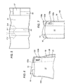
Figure 1 is a perspective view of a preferred embodiment of the bag according to the invention in a bag closed condition; -
Figure 2A is a side view showing the first preferred embodiment of the bag in an empty and flattened condition; -
Figure 2B is a section view through the line IIB-IIB ofFigure 2A illustrating the first embodiment of the bag in an empty and flattened condition; -
Figure 2C is a section view through the line IIC-IIC ofFigure 2A illustrating the first embodiment of the bag in an empty and flattened condition; -
Figure 3 is a perspective view showing the first preferred embodiment of the bag in an open condition; -
Figure 4 is a perspective view showing the first preferred embodiment of the bag in the condition where the product contained is being poured out; -
Figure 5 is a top plan view of the web of film used in a first process for making the first preferred embodiment of the bag; -
Figure 6 is a schematic perspective view of a second preferred embodiment of the bag; -
Figure 7 illustrates the second preferred embodiment of the bag in the condition where the gussets are spaced apart; -
Figure 8 is a side view of a third preferred embodiment of the bag in an empty condition; -
Figures 9 and 10 are perspective views of a second process for making the first preferred embodiment of the bag; -
Figure 11 is a perspective view of a third process for making the first preferred embodiment of the bag; -
Figure 12 is a perspective view of a fourth process for making the first preferred embodiment of the bag; -
Figure 13 is a side view of a fourth preferred embodiment of the bag; -
Figure 14 is a side view of a fifth preferred embodiment of the bag; -
Figure 15 is a top plan view of the web of film used in a fifth process for making the bag according to the invention; -
Figure 16 is a schematic side view showing a sixth preferred embodiment of the bag; -
Figure 17 is a schematic side view showing a seventh preferred embodiment of the bag; -
Figure 18 is a schematic side view showing an eighth preferred embodiment of the bag; -
Figure 19 is a schematic side view showing a ninth preferred embodiment of the bag; -
Figure 20 is a schematic perspective view of the ninth preferred embodiment of the bag; -
Figure 21 is a schematic perspective view of a tenth preferred embodiment of the bag; -
Figure 22 is a schematic perspective view of the tenth preferred embodiment of the bag. -
Figures 1 to 4 illustrate a firstpreferred embodiment 10 of a bag made according to this invention. - The bag is preferably designed to contain a food product, including a pet food, or a product that is preferably in the form of a granular product or a product in pieces.
- The bag might however be adapted to contain other products, in liquid or powder form, such as for example a detergent or the like.
- As will become clearer as this description continues, the bag is made preferably by folding a web of film, in particular layered plastic film exhibiting suitable flexibility.
- In particular, for making a bag according to the embodiment shown in
Figure 1 , it is contemplated the use of a web of plastic or plasticized film, where said film has a sealable face, in particular heat-sealable, and an opposite face which is not sealable and which is printed with appropriate writing, colours and images on predetermined areas of it, corresponding to predetermined parts of the front, rear and side faces of the finished bag. - As shown in the drawings, the
bag 10 comprises afront wall 12, arear wall 14 andopposite side walls - As illustrated, the gussets or
side walls flaps respective edges rear walls - The
reference numerals panels - The top of the bag is closed along a join portion, in particular a
transversal seal 41 described in more detail below. - The bottom of the
bag 10 is defined by atransversal strip 44 made by joining or sealing opposite lowertransversal ends rear walls - As shown in
Figure 1 , when the bag is full, the lower portions or zones of the front andrear walls Figure 1 , thebottom part front wall 12, thus giving the bag an enlarged or flat bottom in which the lower portion of thewall 14 forms the lower transversal face of the bag when full. - In this condition, the lower portion of the bag, which is folded over the
front wall 12, is pressed against and glued to the respective portion of the rear wall in a manner well within the knowledge of an expert in the trade and therefore not described in further detail. Obviously, the bottom portion might also be folded over and fixed to therear wall 14. - At the top of it, the bag according to the invention has a
product outlet mouth 30, which is described in more detail below, where there are means for opening and closing themouth 30, for example in the form of a zip, comprising respective connecting elements that can be fastened and unfastened to and from each other, and more specifically, unfastened by pulling apart the respective portions of the front andrear bag walls rear walls - As illustrated, there are longitudinal seals or joins, labelled 31s, 33s, 35s, 37s, at the
edges front wall 12 and therear wall 14 with theportions - As illustrated, the
bag 10 comprisesside gussets gusset 18, as shown inFigure 2A , is closed by a band orstrip 40 designed to seal that end of the gusset to prevent communication between the inside and outside of the bag. Preferably, therefore, theband 40 constitutes means for hermetically sealing the bag. - The
band 40 is suitably glued or sealed above the upper end 18' of thegusset 18 which is in contact with a respective wall of the bag or, more specifically, in this embodiment, with the inside face of thewall 14. Theband 40 is also glued or sealed to the respective inside face 14' of thewall 14 of the bag. - Advantageously, the
bag 10 comprises a joiningportion 33 between thefront wall 12 and therear wall 14 of the bag, said joiningportion 33 being provided on the extension of therespective flaps gusset 16. - Advantageously, the joining
portion 33 is adapted to form gripping means for gripping the bag, located on the extension of therespective gusset 18 and, as may be inferred in particular fromFigure 4 , the joiningportion 33 is wide enough to be engaged by at least one finger and, in particular, by a plurality of fingers of the user's hand M. - In this way, it is possible to define a
portion 33 by which the bag can be conveniently gripped and handled, in particular allowing the product P to be poured out of the bag, as clearly illustrated inFigure 4 . - As shown, the joining
portion 33 extends longitudinally along the bag between the end 18' of thegusset 18 and theupper edge 41 that seals the top of the bag. - As illustrated, the joining
portion 33 is delimited by an inner and an outerlongitudinal edge transversal edges - Further, as illustrated, the joining
portion 33 extends transversally for at least part of the width of the respective gusset, and more specifically, until it reaches the longitudinal extension of theinner edge 18a of therespective gusset 18. - The joining portion or gripping means might, however, also be made wider than the transversal width of the respective gusset, that is to say, the
inner edge 33a of the joining portion might extend transversally beyond theinner edge 18a of therespective gusset 18. - A large
gripping means 33 easily engaged by the user's fingers is thus obtained. - To facilitate the hold on the
portion 33, at least onehole 35, delimited by a respective edge 35', is made in theportion 33, saidhole 35 being, advantageously in the form of an oblong hole extending longitudinally of the bag, that is to say, parallel to thesides - In this way, the user's hand M can be conveniently positioned as shown in
Figure 4 , inside thehole 35 in such a way that the product P can be easily poured out of thebag 10. - Advantageously, as illustrated, the bag has a first and a
second gusset gusset 16, extends longitudinally beyond the upper longitudinal edge 18' of theother gusset 18. - As stated, in this embodiment, the bag gripping means 33 are provided on the extension of the
short gusset 18, that is to say on a longitudinal zone without thegussetted portion 18. - In an especially advantageous manner, the
gusset 16 is in turn adapted to form means for channelling the product P out of thebag 10, as clearly shown inFigure 4 . - In practice, the presence of a longer gusset is 16 is used as means for channelling the product P out of the
bag 10. - As illustrated, the
gusset 16 has a respective upper end 16' that is located at theupper boundary 41 of thebag 10. - In practice, a product
P outlet mouth 30 is advantageously provided at theflaps gusset 16. - More specifically, as illustrated, the
mouth 30 is provided at the end 16' of thegusset 16. - Advantageously, at the
outlet mouth 30, thegusset 16 has a respective end section orportion 161 that can be moved between a closed configuration, illustrated inFigure 3 , and a configuration in which the product can be poured out of themouth 30, as illustrated inFigure 4 . - In particular, the
gusset 16 has a longitudinal end 16' such that when thegusset 16 is in the folded in condition towards the inside of the bag, it forms means for at least partly closing theproduct outlet mouth 30. - In practice, the product can be poured out when the
respective flaps gusset 16 are transversally spread apart or extended towards the outside of the bag, as illustrated inFigure 4 . - In particular, the material constituting the film used to make the bag, or at least the gusset, exhibits properties such that the
gusset 16 opens or extends towards the outside of the bag under the weight of the product P contained in the bag and elastically re-closes towards the inside of the bag when the weight of the product P no longer bears on thegusset 16. - As illustrated, the product
P outlet mouth 30 opens at the end 16' of thegusset 16, that is to say, on the transversal side opposite the side where the bag gripping means 33 are located, and is substantially aligned with the gripping means 33 in a transversal direction. - As illustrated, the
outlet mouth 30 is defined by an oblique border, labelled 30', which extends along theend edge 41 of the bag. - This provides a
product outlet mouth 30 that opens longitudinally of the bag. In another embodiment, however, the product outlet mouth might be made in such a manner as to open both transversally, or laterally, and longitudinally of the bag. - As illustrated in particular in
Figure 4 , theoutlet mouth 30 is defined by opposite borders 19', 21' of theflaps respective gusset 16 and by respective borders 126', 146' of the front andrear walls Figure 3 , and which are, instead, inclined in the opposite direction to the borders 19', 21' at the end 16' of thegusset 16, when theend portion 161 of thegusset 16 extends transversally beyond theedges rear walls - In particular, as illustrated, the borders 19', 21' of the
respective flaps gusset 16 extend obliquely in the same way as the borders 126', 146' of the portion of therespective walls respective flaps gusset 16. - In particular, the
mouth 30 extends transversally for substantially the full width of therespective gusset 16. - The
product outlet mouth 30 might, however, also extend for a short transversal section, remaining substantially within the transversal dimension of thegusset 16. As already mentioned, the bag comprises an uppertransversal edge 41 for closing the bag and which is defined by opposite end strips joined together, in particular sealed, on the front andrear walls flaps gusset 16 are opened. - As stated, the
mouth 30 opens at the uppertransversal edge 41. In particular, theproduct outlet mouth 30 opens on one side of the uppertransversal closing edge 41. - As stated, the bag also has longitudinal closing edges, labelled 31s and 33s, provided, respectively, between the
front wall 12 and theopposite gusset flap 19, between therear wall 14 and theopposite flap 21 of thegusset 16, and on the opposite side of the longitudinal closing edges 35s, 37s provided between thefront wall 12 and theopposite flap 23 of thegusset 18 and between therear wall 14 and theopposite flap 25 of thegusset 18. Thelongitudinal edges rear walls respective flaps gussets - As illustrated, the
product outlet mouth 30 opens at respectivelongitudinal edges longitudinal edges rear walls gusset 16. - Advantageously, as may be inferred in particular from
Figure 3 , the longitudinal end 16'a of theedge 16a that joins theflaps gusset 16 extends at thetransversal closing edge 41. - As may be inferred from
Figures 1 and2A , the bag is provided with a tear line, preferably in the form of apre-weakened line 31, for removing acorner portion 10' of the bag, saidpre-weakened line 31 coinciding, once theportion 10' has been removed, with the border delimiting theproduct outlet mouth 30. - The
tear line 31, preferably a pre-weakened line, extends obliquely relative to the principal direction in which the bag extends, that is to say, or at an angle to the longitudinal sides of the bag, and is obtained, as may be better inferred fromFigure 5 , fromrespective sections 319, 321, that extend at the parts of the film which constitute the gusset flaps 19, 21 and which are oriented, starting from a common junction point, in opposite angular directions, and furtheroblique sections 314, 312, that extend at the parts of the film which constitute the front andrear bag walls oblique portions 319, 321. - The tear or
pre-weakened line 31 is advantageously in the form of a part of the plastic film that is thinner than the rest of the film and is, in particular, made by laser thinning. Other means for pre-cutting the film are also imaginable, however, provided always that they keep the bag hermetically sealed before opening. For example, the film might be cut mechanically but without cutting right though it, or the film might simply have a line printed on it indicating that the user should cut it using scissors or another cutting tool. - As illustrated, tearing aid means are provided at the
pre-weakened line 31, in the form ofnotches pre-weakened line 30, saidnotches transversal closing edge 41, as well illustrated inFigure 2A . - Means 40 are also advantageously provided for sealing the respective end 18' of the
gusset 18, said means, as mentioned above, being in the form of ashort sealing band 40 extending only at the end 18' of theshort gusset 18. - The
portion 33 defining the bag gripping means extends at the sealing means 40 of thegusset 18 end 18'. - The
numerals gripping means 33 are located, or, other words, at the bottom of thebag 10. - In particular, the
bag gripping means gussets - More specifically, as illustrated, second gripping means 53 are provided on the
side 18 of the bag, and third gripping means 63 on theother side 16 of the bag. - In practice, second gripping means 53, located at the bottom of the bag on the
side 18 of the bag, are longitudinally aligned with the firstgripping means 33, while third gripping means 63, located at the bottom of the bag on theside 16 of the bag, are longitudinally aligned with theoutlet mouth 30. - The gripping means 53 and 63 at the bottom of the bag comprise
respective holes respective edges 55', 65 and into which the user can insert at least one finger. - As illustrated, the gripping
means rear walls - In practice, it is contemplated the provision of a first and a second portion defining the second and third
gripping means means - As illustrated, the
product outlet mouth 30 opens only on one side of a lateral area of the bag. - In practice, the bag thus has an upper area where the
product outlet mouth 30 is made and a bottom area longitudinally opposite it. As illustrated, the bag comprises gripping means 33 extending at the top of the bag and, more specifically, at the uppertransversal edge 41 of the bag. - Further, as illustrated, the bag gripping means 33 extend longitudinally beyond the bottom edge of the
mouth 30 towards the bottom of the bag, thus facilitating the tasks of pouring out the product and generally handling and transporting the bag. - According to another aspect, the bag gripping means 33 are provided on one side of the bag, and, in particular, on the extension of a
respective gusset 18, in an area situated beyond the upper longitudinal edge of that gusset. These gripping means, as clearly shown inFigure 4 are in the form of advantageous means that can be held or gripped by the user's fingers in opposition to the palm of the hand. Thus, the user's fingers are wrapped around grippingmeans 35", as may be inferred fromFigure 4 . - In practice, the gripping means 35" located between the
opening 35 and the respective outer lateral edge of the bag constitutes a handy elongated grip extending longitudinally of the bag along the outer lateral edge of the bag. - From
Figure 5 it may be inferred that an advantageous process for making the firstpreferred embodiment 10 of the bag according to the invention comprises feeding a flat web offilm 51 suitable for making thebag 10, providing anarea 58 of theweb 51, where thebag gusset 18 will be formed, with anopening 57 and cutting a line, in particular using laser means, in a portion of the web transversally aligned with saidopening 57, that is to say, in aportion 56 of the film where thegusset 16 of thebag 10 will be formed. - Said laser cut, as described above, comprises a first section 319, a
second section 321, together defining a shape substantially like a V, a third section 312 on the extension of the section 319 and forming with the latter a portion having a general V shape, and afourth section 314 on the extension of thesection 321 and forming with the latter a portion having a general V shape, said sections together forming the pre-cut area designed to make theproduct outlet mouth 30 in the finished bag. - In order to obtain the bag using the first preferred embodiment of the process, the method to be followed is substantially that described in international patent application
WO2006/067617 or explained in Italian patent applicationBO2007A000230 - In a second
preferred embodiment 100 illustrated inFigures 6 and 7 , thebag gripping portion 133 at the upper longitudinal end of the bag can be made by sealing the respective ends of agusset 18. - In practice, a
first portion 133a is provided between theflap 23 of thegusset 18 and thefront wall 12 and asecond portion 133b is provided between theflap 25 of thegusset 18 and therear wall 14, both portions being suitably perforated to affordrespective openings 135a and 135b for gripping and holding the bag. - It is then contemplated joining, in particular by sealing, the perforated gripping
portions gripping portion 133, as illustrated inFigure 6 , thanks to the provision of respective openings, not illustrated in detail in the accompanying drawings, in theflaps gusset 18, which enable the sealable inside faces of the front andrear walls wall 12 can thus be made to adhere to thewall 14 to create a singlegripping portion 133. - In practice, in this second
preferred embodiment 100, thegussets - In a third
preferred embodiment 200 of the bag, illustrated inFigure 8 , similar to thefirst embodiment 10 and where the parts that are the same as those of the latter are denoted by the same reference numerals and, for brevity, will not be described in detail again, a first and asecond band respective gussets upper edge 41 of the bag. - In this third preferred embodiment, there are
oblique seals respective bands gussets rear walls - A second preferred embodiment of the process for making the bag, in particular for making the first preferred embodiment of the bag, is illustrated in
Figures 9 and 10 . This second preferred embodiment of the process contemplates the use of a plurality of webs offilm respective rolls film film - Advantageously, as illustrated in particular in
Figure 10 , the webs ofgusset film gussets long gussets 316 extending for substantially the entire width of thewebs short gussets 318 extending from one lateral edge of thewebs respective webs bag gripping portion 33 is subsequently made at theshort gusset 318 of the bag. - A third preferred embodiment of the process for making the bag, in particular for making the first preferred embodiment of the bag, is illustrated in
Figure 11 . This third preferred embodiment of the process contemplates the use of a plurality of webs offilm film film - Advantageously, as illustrated in
Figure 11 , the webs ofgusset film gussets 418, 416 are made in different lengths, and more specifically, long gussets 416 andshort gussets 418, where thebag gripping portion 33 is subsequently made, substantially as described in connection with the process ofFigures 9 and 10 described above. - A fourth preferred embodiment of the process for making the bag, in particular for making the first preferred embodiment of the bag, is illustrated in
Figure 12 . This fourth preferred embodiment of the process contemplates the use of a plurality of webs offilm film film - Advantageously, as illustrated in
Figure 12 , the webs ofgusset film gusset film 553 to form longitudinally spacedportions opening 553a between them, where thebag gripping portion 33 is subsequently made. - In order to obtain the bag using the fourth preferred embodiment of the process, the method to be followed is substantially that described in international patent application
WO2006/067617 or explained in Italian patent applicationBO2007A000230 -
Figure 13 illustrates a fourthpreferred embodiment 600 of the bag, which is similar to thethird embodiment 200 and in which the components similar to those of that embodiment are labelled with the same reference numerals and, for brevity, will not be described again in detail. - In the fourth preferred embodiment of the bag, the
gussets rear walls -
Figure 14 illustrates a fifthpreferred embodiment 700 of the bag, which is similar to thethird embodiment 200 and in which the components similar to those of that embodiment are labelled with the same reference numerals and, for brevity, will not be described again in detail. In the fifth preferred embodiment of the bag, it is contemplated the provision of apre-weakened line 731 for removing a corner portion of the bag, where alongitudinal section 731 a of thepre-weakened line 731 extends on the front and rear walls of the bag, and atransversal section 731b runs on the front and rear walls and on the gusset flaps. Thepre-weakened line 731 is advantageously in the form of a part of the plastic film that is thinner than the rest of the film and is, in particular, made by laser thinning. Tearing aid means or notches 731c, 731d similar to those of thefirst embodiment 10 are advantageously provided at thepre-weakened line 731. This provides a product outlet mouth that opens both longitudinally and transversally of the bag. - The bands or strips 40, 140a, 140b for sealing the gussets are made preferably of heat-sealable material, and especially of material that is heat sealable on both sides or faces.
- A fifth preferred embodiment of the process for making the bag is illustrated in
Figure 15 . The fifth preferred embodiment of the process is particularly suitable for making a bag having an L-shaped product outlet mouth, that is, a mouth delimited by a border or portion extending transversally of the bag and a border or portion extending longitudinally of the bag in a manner similar that described in connection with the fifth preferred embodiment of the bag illustrated inFigure 14 . - In the fifth preferred embodiment of the process, the lateral product outlet mouth is obtained by pre-cutting or weakening the portions of film defining the gusset flaps and the respective portions of the film defining the front and rear walls of the finished bag.
- In practice, as shown in
Figure 15 , the pre-cutting or thinning of the film, accomplished preferably by a laser beam emitting device, is defined by a first transversal portion, or line, 771 running along alongitudinal area 756, where a respective side gusset is made on the bag, and across thelongitudinal lines rear walls - The pre-cutting or thinning of the film also comprises respective longitudinal sections or
lines line 771 to a longitudinal area of the film that will form the transversal upper end edge of the bag. - As illustrated, the pre-cut or pre-weakened area of the film defined in its entirety by the
line pre-weakened line opening 757 made by punching the web offilm 751 and located at thefilm portion 758 defining a respective flap of a side gusset of the bag. - This creates an outlet mouth for advantageously and effectively channelling the product out of the bag and a pre-cut weakened area that is quick and easy to make.
- In order to obtain the bag using the fifth preferred embodiment of the process, the method to be followed is substantially that described in international patent application
WO2006/067617 or explained in Italian patent applicationBO2007A000230 -
Figure 16 illustrates the top of a sixthpreferred embodiment 800 of the bag, which is similar to thefirst embodiment 10 and in which the components similar to those of that embodiment are labelled with the same reference numerals and, for brevity, will not be described again in detail. In the sixth preferred embodiment of the bag, the invention contemplates the provision of a pre-cut line, preferably apre-weakened line 813 for removing a corner portion of the bag, where saidpre-cut line 813 extends between the laterallongitudinal edges transversal edge 41 of the bag. - The sixth preferred embodiment differs from the first preferred embodiment in that it has a
pre-cut line 813 which extends at the front andrear bag walls inside edge 16a of thegusset 16. -
Figure 17 illustrates the top of a seventhpreferred embodiment 820 of the bag, which is similar to thefirst embodiment 10 and in which the components similar to those of that embodiment are labelled with the same reference numerals and, for brevity, will not be described again in detail. - In the seventh preferred embodiment of the bag, the invention contemplates the provision of a pre-cut line, preferably a
pre-weakened line 823 for removing a corner portion of the bag, where saidpre-cut line 823 extends between the laterallongitudinal edges transversal edge 41 of the bag. - The seventh preferred embodiment, too, differs from the first preferred embodiment in that it has a
pre-cut line 823 which extends at the front andrear bag walls inside edge 16a of thegusset 16. - Besides that, the seventh preferred embodiment differs from the first and sixth preferred embodiments in that the
pre-cut line 823 is divided into a first and asecond part - In particular, the
first part 823a of the pre-cut line extends from thegusset 16 at an angle Aa to the longitudinal direction of the bag, said angle Aa being greater than the angle Ab made by thesecond part 823b of the pre-cut line extending from theupper edge 41 of the bag. - In this way, it is easy for the user to tear the bag along the pre-cut line to make an advantageously large opening near the respective lateral edge of the bag, that is to say, near the respective gusset, with obvious advantages in terms of channelling the product out of the bag.
- As illustrated, the
first part 823a of the pre-cut line extending from thelateral edge gusset 16 and beyond theinside edge 16a of the gusset makes an obtuse angle A, that is, greater than 90°, with thesecond part 823a of the pre-cut line extending from theupper edge 41 of the bag. -
Figure 18 illustrates the top of a eighthpreferred embodiment 840 of the bag, which is similar to thefirst embodiment 10 and in which the components similar to those of that embodiment are labelled with the same reference numerals and, for brevity, will not be described again in detail. - In the eighth preferred embodiment of the bag, the invention contemplates the provision of a pre-cut line, preferably a
pre-weakened line 843 for removing a corner portion of the bag, where saidpre-cut line 843 extends between the laterallongitudinal edges transversal edge 41 of the bag. - The eighth preferred embodiment, too, like the sixth and seventh embodiments, differs from the first preferred embodiment in that it has a
pre-cut line 843 which extends at the front and rear bag walls transversally beyond theinside edge 16a of thegusset 16. - Advantageously, the
pre-cut line 843 of the eighth preferred embodiment has an arcuate shape both on the front andrear walls gusset 16, as clearly shown inFigure 19 , which illustrates a bag with a similar opening cut. - As illustrated, the
pre-cut line 843 extends from an outer edge of the bag in a direction substantially perpendicular to the respectivelongitudinal edge transversal closing line 41 of the bag. - In practice, this provides an
outlet mouth 30 which extends across part of the width of the bag, and more specifically, for slightly more than half the width of therespective gusset 16, and which is conveniently large and effective in channelling or guiding the product out of the bag. -
Figures 19 and 20 illustrate the top of a ninthpreferred embodiment 850 of the bag, which is similar to thefirst embodiment 10 and in which the components similar to those of that embodiment are labelled with the same reference numerals and, for brevity, will not be described again in detail. - The ninth preferred embodiment of the bag advantageously comprises means 861 for closing the
product outlet mouth 30 after the bag has been opened. - Advantageously, the closing means 861 are designed to keep the
outlet mouth 30 closed after the bag has been opened and are provided at or near theproduct outlet mouth 30 itself. - The means 861 for closing
product outlet mouth 30 are integral with the bag and are embodied by means forming part of themouth 30 and designed to keep the top 850' of the bag at theproduct outlet mouth 30 closed by keeping it in a folded condition, as illustrated inFigure 20 , over an outside face of therespective bag wall 14 to which it is suitably fixed. - In particular, the means for closing or folding the top 850' of the bag comprise a
tab 861, preferably made from a strip of film and having oneportion 861a that is integral with or fixed to an outside face of onebag wall 12 and anotherportion 861b designed to adhere or be fastened to the outside face of theopposite wall 14 of the bag. - As illustrated in
Figure 19 , theclosing tab 861 before use is in a disengaged condition at the top of the bag and of thegusset 16, being located just under the respective portion of theline 843 that delimits theproduct outlet mouth 30. - As may be clearly inferred from the drawings, the length of the
tab 861 and its distance from theline 843 that delimits theproduct outlet mouth 30 are such that when it is used it folds the top 850' of the bag at theproduct outlet mouth 30, that is to say, at theside gusset 16, over an outside face of thebag wall 14. - The part 850' of the bag at the
gusset 16 is folded with respect to anoblique line 850" inclined at an angle to the longitudinal direction of the bag, theclosing tab 861 extending in a direction perpendicular to thefold line 850". -
Figures 21 and 22 illustrate the top of a tenthpreferred embodiment 900 of the bag, which is similar to thefirst embodiment 10 and in which the components similar to those of that embodiment are labelled with the same reference numerals and, for brevity, will not be described again in detail. The tenth preferred embodiment of the bag advantageously comprises means 911 for closing theproduct outlet mouth 30 after the bag has been opened. - Advantageously, the means for closing or keeping in a closed condition the
outlet mouth 30 are in the form ofmeans 911 designed to keep theflaps gusset 16 close to each other after the bag has been opened, and are provided at or near theproduct outlet mouth 30 itself. - More specifically, the
means 911 for keeping theflaps gusset 16 close to each other are integral with the bag and located at the top of the bag and of thegusset 16, under the respective portion of the pre-cut line, or edge, 843 delimiting theproduct outlet mouth 30. - In particular, the means for keeping the gusset flaps close to each other at the product outlet mouth comprise mutually engageable and disengageable means 911a, 911b applied to the facing surfaces of the
opposite flaps gusset 16. - Looking in more detail, the engageable and disengageable means comprise a
respective element 911a fixed to the outside face of thegusset flap 19 and having adhesion means for connecting it to anelement 911b fixed to the outside face of theopposite gusset flap 21. - In practice, the mutually engageable and disengageable means 911a and 911b, which keep the opposite gusset flaps 19, 21 close to each other in the closed or mutually engaged condition are provided on the face of the
flap flap - In practice, the mutually engageable and disengageable means 911a and 911b are preferably in the form of Velcro strips or other suitable means that can be fastened to each other.
- In the embodiments of the bag described above, the means for gripping or holding the bag are located, preferably, at or near the respective longitudinal end edge of the bag. It will be understood, however, that in another embodiment, the means for gripping or holding the bag might be provided at any other intermediate longitudinal position of the respective lateral edge or area of the bag.
- The invention described above is susceptible of industrial application and may be modified and adapted in several ways without thereby departing from the scope of the inventive concept defined by the appended claims, Moreover, all the details of the invention may be substituted by technically equivalent elements.
Claims (15)
- A bag (10) for containing a product (P), especially a food product that is preferably in the form of a granular product or a product in pieces, the bag having a containing body made preferably of a flexible material such as a plastic film, and comprising a front wall (12), a rear wall (14) and at least one gusset (16, 18) defined by opposite flaps (19, 21, and 23, 25), in particular a first and a second side gusset (16, 18), the bag comprising a product (P) outlet mouth (30) that opens at the flaps (19, 21) of the gusset (16), and having first gripping means (33) by which the bag can be gripped, located on one side of the bag which is the side opposite to the product outlet mouth (30), characterized in that the first bag gripping means (33) comprises a joining portion (33, 133a, 133b) having at least one hole (35) made in it for gripping and holding the bag, and that the bag comprises second gripping means (53) for gripping the bag on the same longitudinal side opposite the side where the first gripping means (33) are located, said second bag gripping means (53) being substantially aligned with the first gripping means (33) and having at least one hole (55) for gripping and holding the bag.
- The bag according to claim 1, characterized in that the respective gusset (16) at the outlet mouth (30) can be moved between a configuration in which the product outlet mouth (30) is at least partly closed and a configuration in which the product (P) can be poured freely out of the mouth (30) and which is the result of the respective gusset flaps (19, 21) being extended towards the outside of the bag.
- The bag according to any of the foregoing claims, characterized in that the joining portion (33) constituting first bag gripping means is between the front wall (12) and the rear wall (14) of the bag, and is provided on the extension of the flaps (23, 25) of the respective gusset (18) .
- The bag according to any of the foregoing claims, characterized in that the first bag gripping means (33) is on the extension of a respective gusset (18) and is transversally aligned with the product (P) outlet mouth (30).
- The bag according to any of the foregoing claims, characterized in that the joining portion (33) extends longitudinally between the end (18') of the respective gusset (18) and the upper edge (41) of the bag.
- The bag according to any of the foregoing claims, characterized in that the hole (35) of the first gripping means (33) is in the form of an oblong hole extending longitudinally of the bag.
- The bag according to any of the foregoing claims, characterized in that it comprises a gusset (16) that extends longitudinally beyond the longitudinal end (18') of the other gusset (18), the first bag gripping means (33) being located on the extension of the short gusset (18).
- The bag according to any of the foregoing claims, characterized in that it comprises a pre-cut line (31) for tearing off a portion (10') of the bag and defining a product (P) outlet mouth (30) which is used to remove a corner portion (10') of the bag.
- The bag according to claim 8, characterized in that the pre-cut line (31) is in the form of a part of the material the bag is made of that is thinner than the rest of the material, the pre-cut line (31) being in the form of a thinned part obtained by laser thinning.
- The bag according to any of the foregoing claims 8 or 9, characterized in that the pre-cut line (31) extends on the flaps (19, 21) of the respective gusset (16).
- The bag according to any of the foregoing claims from 8 to 10, characterized in that the pre-cut line (31) extends on the front and rear walls (12, 14) of the bag.
- The bag according to any of the foregoing claims, characterized in that it comprises means (40) for sealing the respective end (18') of the gusset (18).
- The bag according to claim 12, characterized in that the means (40) for sealing the end (18') of the gusset (18) are in the form of a sealing band (40).
- The bag according to any of the foregoing claims, characterized in that it comprises means (53, 63) for gripping the bag located at the bottom of the bag.
- The bag according to any of the foregoing claims, characterized in that it comprises means (53, 63) for gripping the bag located at the respective gusset (16, 18).
Applications Claiming Priority (2)
| Application Number | Priority Date | Filing Date | Title |
|---|---|---|---|
| IT000387A ITBO20070387A1 (en) | 2007-05-31 | 2007-05-31 | BAG FOR THE CONTAINMENT OF A PRODUCT AND PROCEDURE FOR THE REALIZATION OF SUCH A BAG. |
| PCT/IB2008/001357 WO2008146142A1 (en) | 2007-05-31 | 2008-05-29 | Bag for containing a product and process for making the bag |
Publications (2)
| Publication Number | Publication Date |
|---|---|
| EP2150471A1 EP2150471A1 (en) | 2010-02-10 |
| EP2150471B1 true EP2150471B1 (en) | 2011-07-20 |
Family
ID=39860736
Family Applications (1)
| Application Number | Title | Priority Date | Filing Date |
|---|---|---|---|
| EP08762735A Not-in-force EP2150471B1 (en) | 2007-05-31 | 2008-05-29 | Bag for containing a product |
Country Status (4)
| Country | Link |
|---|---|
| EP (1) | EP2150471B1 (en) |
| AT (1) | ATE517042T1 (en) |
| IT (1) | ITBO20070387A1 (en) |
| WO (1) | WO2008146142A1 (en) |
Families Citing this family (33)
| Publication number | Priority date | Publication date | Assignee | Title |
|---|---|---|---|---|
| US9150342B2 (en) | 2003-04-16 | 2015-10-06 | Intercontinental Great Brands Llc | Resealable tray container |
| US7963413B2 (en) | 2006-05-23 | 2011-06-21 | Kraft Foods Global Brands Llc | Tamper evident resealable closure |
| US8308363B2 (en) | 2006-05-23 | 2012-11-13 | Kraft Foods Global Brands Llc | Package integrity indicator for container closure |
| US8114451B2 (en) | 2006-12-27 | 2012-02-14 | Kraft Foods Global Brands Llc | Resealable closure with package integrity feature |
| US8408792B2 (en) | 2007-03-30 | 2013-04-02 | Kraft Foods Global Brands Llc | Package integrity indicating closure |
| US20100018974A1 (en) | 2008-07-24 | 2010-01-28 | Deborah Lyzenga | Package integrity indicating closure |
| GB0819200D0 (en) | 2008-10-20 | 2008-11-26 | Cadbury Holdings Ltd | Packaging |
| SE534097C2 (en) * | 2008-10-22 | 2011-04-26 | Ecolean Res & Dev As | Resealable packaging |
| US20100150481A1 (en) * | 2008-12-17 | 2010-06-17 | Perell Willaim S | Package for consumer products |
| ITBO20090059A1 (en) * | 2009-02-06 | 2010-08-07 | Bordi Carlo S R L | BAG AND PROCEDURE FOR THE REALIZATION OF A BAG. |
| DK2347971T3 (en) | 2010-01-26 | 2012-09-17 | Gen Biscuit | Re-sealable food packaging and manufacturing processes |
| US8814430B2 (en) | 2010-02-23 | 2014-08-26 | Kraft Foods R&D, Inc. | Food package having opening feature |
| DK2368811T3 (en) | 2010-03-23 | 2012-09-24 | Gen Biscuit | Reclosable packaging for food products as well as manufacturing process |
| PE20130940A1 (en) | 2010-05-18 | 2013-09-02 | Intercontinental Great Brands Llc | FLEXIBLE PACKAGING THAT CAN BE CLOSED AGAIN AND METHODS OF MANUFACTURING THE SAME |
| US9656783B2 (en) | 2010-05-18 | 2017-05-23 | Intercontinental Great Brands Llc | Reclosable flexible packaging and methods for manufacturing same |
| GB201020165D0 (en) * | 2010-11-29 | 2011-01-12 | Reckitt Benckiser Nv | Product |
| WO2012125945A1 (en) | 2011-03-17 | 2012-09-20 | Kraft Foods Global Brands Llc | Reclosable flexible film packaging products and methods of manufacture |
| US9845184B2 (en) | 2012-02-13 | 2017-12-19 | Polytex Fibers Corporation | Easy open plastic bags |
| US9669981B2 (en) | 2012-02-13 | 2017-06-06 | Polytex Fibers Corporation | Easy open plastic bags |
| US11459157B2 (en) | 2012-02-13 | 2022-10-04 | Polytex Fibers Llc | Woven plastic bags with features that reduce leakage, breakage and infestations |
| US9969529B2 (en) | 2012-02-13 | 2018-05-15 | Polytex Fibers Corporation | Easy open plastic bags |
| US10562689B2 (en) | 2012-02-13 | 2020-02-18 | Polytex Fibers Corporation | Woven plastic bags with features that reduce leakage, breakage and infestations |
| US10661963B2 (en) | 2014-04-04 | 2020-05-26 | Polytex Fibers Corporation | Peelable easy open plastic bags |
| US9731868B2 (en) | 2012-10-12 | 2017-08-15 | Polytex Fibers Corporation | Polymeric bags with easy access features attached to the bags without adhesives |
| CA2898267A1 (en) * | 2013-01-22 | 2014-07-31 | Polytex Fibers Corporation | Easy access non-woven plastic bags |
| WO2014116567A1 (en) | 2013-01-22 | 2014-07-31 | Polytex Fibers Corporation | Easy access woven plastic bags |
| US9981792B2 (en) | 2014-03-07 | 2018-05-29 | Poppack Llc | Package for humanitarian efforts with unique reclosing mechanism |
| MX2016013051A (en) | 2014-04-04 | 2017-02-15 | Polytex Fibers Corp | Woven plastic bags with features the reduce leakage, breakage and infestations. |
| US11305927B2 (en) | 2014-04-04 | 2022-04-19 | Polytex Fibers Llc | Easy open plastic bags |
| US11472622B2 (en) | 2014-04-04 | 2022-10-18 | Polytex Fibers Llc | Woven plastic bags with features that reduce leakage, breakage, and infestations |
| JP6672650B2 (en) * | 2015-09-08 | 2020-03-25 | 凸版印刷株式会社 | Manufacturing method of self-standing packaging bag with spout |
| US10106301B2 (en) * | 2016-08-30 | 2018-10-23 | Dow Global Technologies Llc | Flexible container with spout |
| JP7284846B1 (en) | 2022-03-11 | 2023-05-31 | 福助工業株式会社 | packaging bag |
Family Cites Families (10)
| Publication number | Priority date | Publication date | Assignee | Title |
|---|---|---|---|---|
| US2093977A (en) * | 1935-07-20 | 1937-09-21 | John A Farmer | Bag closure |
| US5062716A (en) * | 1990-03-07 | 1991-11-05 | Kimberly-Clark Corp. | Staged release bag and method for making |
| DE9207558U1 (en) * | 1992-06-04 | 1992-10-29 | Imer, Rodney Haydn, Dipl.-Ing., 4000 Duesseldorf, De | |
| US6206571B1 (en) * | 1999-06-24 | 2001-03-27 | Alan D. Olin | Flexible bag with resealable pour spout |
| US6352365B1 (en) * | 2000-08-08 | 2002-03-05 | Colgate Palmolive Company | Bag with spout |
| US6971794B2 (en) * | 2003-04-15 | 2005-12-06 | Innoflex Incorporated | Package having reclosable pour spout and method of forming same |
| WO2006067617A1 (en) * | 2004-12-23 | 2006-06-29 | Marco Reggi | Method for making a bag |
| DE102006029119A1 (en) * | 2006-06-22 | 2007-07-05 | Nordenia Deutschland Halle Gmbh Werk Steinfeld | Film bag, has folding edges between first lateral edge and the front surface and rear surface, which are stiffends by longitudinal sealed seams, which extend up to top sealing seam |
| DE102006029893B4 (en) * | 2006-06-28 | 2011-04-28 | Nordenia Deutschland Halle Gmbh | foil pouch |
| FR2910884B1 (en) * | 2007-01-03 | 2009-03-06 | Autobar Flexible Packaging Sa | PLASTIC BELLOW BAG FOR FOOD PRODUCTS. |
-
2007
- 2007-05-31 IT IT000387A patent/ITBO20070387A1/en unknown
-
2008
- 2008-05-29 EP EP08762735A patent/EP2150471B1/en not_active Not-in-force
- 2008-05-29 AT AT08762735T patent/ATE517042T1/en not_active IP Right Cessation
- 2008-05-29 WO PCT/IB2008/001357 patent/WO2008146142A1/en active Application Filing
Also Published As
| Publication number | Publication date |
|---|---|
| ATE517042T1 (en) | 2011-08-15 |
| WO2008146142A1 (en) | 2008-12-04 |
| ITBO20070387A1 (en) | 2008-12-01 |
| EP2150471A1 (en) | 2010-02-10 |
Similar Documents
| Publication | Publication Date | Title |
|---|---|---|
| EP2150471B1 (en) | Bag for containing a product | |
| US7300207B2 (en) | Closure for containers and reclosable containers including the same | |
| US6988828B2 (en) | Closure for containers and reclosable containers including the same | |
| AU760569B2 (en) | Bags of easy open construction | |
| US6053635A (en) | Reclosable pouch with reinforced handle | |
| US5611626A (en) | Bag with reenforced handle and resealable pour spout opening | |
| US20170233142A1 (en) | Packaging Bag and Method of Manufacturing the Same | |
| CN102582921A (en) | Improved package having recloseable pour spout | |
| JP2010527857A (en) | Sheet-shaped packaging pack | |
| JP2006523587A (en) | Package with reclosable spout and method of forming the same | |
| US7537387B2 (en) | Bag with handle insert and reclosable by folding | |
| US20120195532A1 (en) | Film bag for packaging of pourable products | |
| GB2421013A (en) | Packaging with line of weakness in gusseted wall | |
| AU607655B2 (en) | A container of flexible material | |
| US10604305B2 (en) | Tamper evident bag | |
| EP1919795B1 (en) | Box-shaped package having an inner and outer package | |
| EP3386883B1 (en) | Food package having a reclosable opening feature and method of opening, removing a food product and reclosing a reclosable food package | |
| WO2009095806A2 (en) | Bag with handle | |
| EP3539892B1 (en) | Reclosable bag and methods of forming and using same | |
| CN108778947A (en) | Resealing formula device for opening and the packing material of such device for opening can be included | |
| AU2002242492B2 (en) | Bag with handle insert and reclosable by folding | |
| CA2349067A1 (en) | Removable slit cover for flexible plastic container bag | |
| AU2002242492A1 (en) | Bag with handle insert and reclosable by folding | |
| MXPA01000139A (en) | Bags of easy open construction |
Legal Events
| Date | Code | Title | Description |
|---|---|---|---|
| PUAI | Public reference made under article 153(3) epc to a published international application that has entered the european phase |
Free format text: ORIGINAL CODE: 0009012 |
|
| 17P | Request for examination filed |
Effective date: 20091125 |
|
| AK | Designated contracting states |
Kind code of ref document: A1 Designated state(s): AT BE BG CH CY CZ DE DK EE ES FI FR GB GR HR HU IE IS IT LI LT LU LV MC MT NL NO PL PT RO SE SI SK TR |
|
| AX | Request for extension of the european patent |
Extension state: AL BA MK RS |
|
| 17Q | First examination report despatched |
Effective date: 20100604 |
|
| DAX | Request for extension of the european patent (deleted) | ||
| GRAP | Despatch of communication of intention to grant a patent |
Free format text: ORIGINAL CODE: EPIDOSNIGR1 |
|
| GRAC | Information related to communication of intention to grant a patent modified |
Free format text: ORIGINAL CODE: EPIDOSCIGR1 |
|
| RTI1 | Title (correction) |
Free format text: BAG FOR CONTAINING A PRODUCT |
|
| GRAC | Information related to communication of intention to grant a patent modified |
Free format text: ORIGINAL CODE: EPIDOSCIGR1 |
|
| GRAS | Grant fee paid |
Free format text: ORIGINAL CODE: EPIDOSNIGR3 |
|
| GRAA | (expected) grant |
Free format text: ORIGINAL CODE: 0009210 |
|
| AK | Designated contracting states |
Kind code of ref document: B1 Designated state(s): AT BE BG CH CY CZ DE DK EE ES FI FR GB GR HR HU IE IS IT LI LT LU LV MC MT NL NO PL PT RO SE SI SK TR |
|
| REG | Reference to a national code |
Ref country code: GB Ref legal event code: FG4D |
|
| REG | Reference to a national code |
Ref country code: CH Ref legal event code: EP |
|
| REG | Reference to a national code |
Ref country code: DE Ref legal event code: R096 Ref document number: 602008008393 Country of ref document: DE Effective date: 20110915 |
|
| REG | Reference to a national code |
Ref country code: NL Ref legal event code: VDEP Effective date: 20110720 |
|
| REG | Reference to a national code |
Ref country code: AT Ref legal event code: MK05 Ref document number: 517042 Country of ref document: AT Kind code of ref document: T Effective date: 20110720 |
|
| PG25 | Lapsed in a contracting state [announced via postgrant information from national office to epo] |
Ref country code: HR Free format text: LAPSE BECAUSE OF FAILURE TO SUBMIT A TRANSLATION OF THE DESCRIPTION OR TO PAY THE FEE WITHIN THE PRESCRIBED TIME-LIMIT Effective date: 20110720 Ref country code: NO Free format text: LAPSE BECAUSE OF FAILURE TO SUBMIT A TRANSLATION OF THE DESCRIPTION OR TO PAY THE FEE WITHIN THE PRESCRIBED TIME-LIMIT Effective date: 20111020 Ref country code: IS Free format text: LAPSE BECAUSE OF FAILURE TO SUBMIT A TRANSLATION OF THE DESCRIPTION OR TO PAY THE FEE WITHIN THE PRESCRIBED TIME-LIMIT Effective date: 20111120 Ref country code: SE Free format text: LAPSE BECAUSE OF FAILURE TO SUBMIT A TRANSLATION OF THE DESCRIPTION OR TO PAY THE FEE WITHIN THE PRESCRIBED TIME-LIMIT Effective date: 20110720 Ref country code: PT Free format text: LAPSE BECAUSE OF FAILURE TO SUBMIT A TRANSLATION OF THE DESCRIPTION OR TO PAY THE FEE WITHIN THE PRESCRIBED TIME-LIMIT Effective date: 20111121 Ref country code: LT Free format text: LAPSE BECAUSE OF FAILURE TO SUBMIT A TRANSLATION OF THE DESCRIPTION OR TO PAY THE FEE WITHIN THE PRESCRIBED TIME-LIMIT Effective date: 20110720 Ref country code: BE Free format text: LAPSE BECAUSE OF FAILURE TO SUBMIT A TRANSLATION OF THE DESCRIPTION OR TO PAY THE FEE WITHIN THE PRESCRIBED TIME-LIMIT Effective date: 20110720 Ref country code: NL Free format text: LAPSE BECAUSE OF FAILURE TO SUBMIT A TRANSLATION OF THE DESCRIPTION OR TO PAY THE FEE WITHIN THE PRESCRIBED TIME-LIMIT Effective date: 20110720 Ref country code: FI Free format text: LAPSE BECAUSE OF FAILURE TO SUBMIT A TRANSLATION OF THE DESCRIPTION OR TO PAY THE FEE WITHIN THE PRESCRIBED TIME-LIMIT Effective date: 20110720 |
|
| PG25 | Lapsed in a contracting state [announced via postgrant information from national office to epo] |
Ref country code: PL Free format text: LAPSE BECAUSE OF FAILURE TO SUBMIT A TRANSLATION OF THE DESCRIPTION OR TO PAY THE FEE WITHIN THE PRESCRIBED TIME-LIMIT Effective date: 20110720 Ref country code: AT Free format text: LAPSE BECAUSE OF FAILURE TO SUBMIT A TRANSLATION OF THE DESCRIPTION OR TO PAY THE FEE WITHIN THE PRESCRIBED TIME-LIMIT Effective date: 20110720 Ref country code: SI Free format text: LAPSE BECAUSE OF FAILURE TO SUBMIT A TRANSLATION OF THE DESCRIPTION OR TO PAY THE FEE WITHIN THE PRESCRIBED TIME-LIMIT Effective date: 20110720 Ref country code: LV Free format text: LAPSE BECAUSE OF FAILURE TO SUBMIT A TRANSLATION OF THE DESCRIPTION OR TO PAY THE FEE WITHIN THE PRESCRIBED TIME-LIMIT Effective date: 20110720 Ref country code: CY Free format text: LAPSE BECAUSE OF FAILURE TO SUBMIT A TRANSLATION OF THE DESCRIPTION OR TO PAY THE FEE WITHIN THE PRESCRIBED TIME-LIMIT Effective date: 20110720 Ref country code: GR Free format text: LAPSE BECAUSE OF FAILURE TO SUBMIT A TRANSLATION OF THE DESCRIPTION OR TO PAY THE FEE WITHIN THE PRESCRIBED TIME-LIMIT Effective date: 20111021 |
|
| PG25 | Lapsed in a contracting state [announced via postgrant information from national office to epo] |
Ref country code: CZ Free format text: LAPSE BECAUSE OF FAILURE TO SUBMIT A TRANSLATION OF THE DESCRIPTION OR TO PAY THE FEE WITHIN THE PRESCRIBED TIME-LIMIT Effective date: 20110720 Ref country code: SK Free format text: LAPSE BECAUSE OF FAILURE TO SUBMIT A TRANSLATION OF THE DESCRIPTION OR TO PAY THE FEE WITHIN THE PRESCRIBED TIME-LIMIT Effective date: 20110720 |
|
| PLBE | No opposition filed within time limit |
Free format text: ORIGINAL CODE: 0009261 |
|
| STAA | Information on the status of an ep patent application or granted ep patent |
Free format text: STATUS: NO OPPOSITION FILED WITHIN TIME LIMIT |
|
| PG25 | Lapsed in a contracting state [announced via postgrant information from national office to epo] |
Ref country code: RO Free format text: LAPSE BECAUSE OF FAILURE TO SUBMIT A TRANSLATION OF THE DESCRIPTION OR TO PAY THE FEE WITHIN THE PRESCRIBED TIME-LIMIT Effective date: 20110720 Ref country code: EE Free format text: LAPSE BECAUSE OF FAILURE TO SUBMIT A TRANSLATION OF THE DESCRIPTION OR TO PAY THE FEE WITHIN THE PRESCRIBED TIME-LIMIT Effective date: 20110720 |
|
| 26N | No opposition filed |
Effective date: 20120423 |
|
| PG25 | Lapsed in a contracting state [announced via postgrant information from national office to epo] |
Ref country code: DK Free format text: LAPSE BECAUSE OF FAILURE TO SUBMIT A TRANSLATION OF THE DESCRIPTION OR TO PAY THE FEE WITHIN THE PRESCRIBED TIME-LIMIT Effective date: 20110720 |
|
| REG | Reference to a national code |
Ref country code: DE Ref legal event code: R097 Ref document number: 602008008393 Country of ref document: DE Effective date: 20120423 |
|
| REG | Reference to a national code |
Ref country code: DE Ref legal event code: R082 Ref document number: 602008008393 Country of ref document: DE Representative=s name: KUTZENBERGER & WOLFF, DE |
|
| PG25 | Lapsed in a contracting state [announced via postgrant information from national office to epo] |
Ref country code: MC Free format text: LAPSE BECAUSE OF NON-PAYMENT OF DUE FEES Effective date: 20120531 |
|
| REG | Reference to a national code |
Ref country code: CH Ref legal event code: PL |
|
| REG | Reference to a national code |
Ref country code: DE Ref legal event code: R081 Ref document number: 602008008393 Country of ref document: DE Owner name: WIPAK BORDI S.R.L., IT Free format text: FORMER OWNER: BORDI CARLO S.R.L., CAORSO, IT Effective date: 20121203 Ref country code: DE Ref legal event code: R082 Ref document number: 602008008393 Country of ref document: DE Representative=s name: KUTZENBERGER & WOLFF, DE Effective date: 20121203 Ref country code: DE Ref legal event code: R082 Ref document number: 602008008393 Country of ref document: DE Representative=s name: KUTZENBERGER WOLFF & PARTNER PATENTANWALTSPART, DE Effective date: 20121203 |
|
| GBPC | Gb: european patent ceased through non-payment of renewal fee |
Effective date: 20120529 |
|
| PG25 | Lapsed in a contracting state [announced via postgrant information from national office to epo] |
Ref country code: CH Free format text: LAPSE BECAUSE OF NON-PAYMENT OF DUE FEES Effective date: 20120531 Ref country code: LI Free format text: LAPSE BECAUSE OF NON-PAYMENT OF DUE FEES Effective date: 20120531 |
|
| REG | Reference to a national code |
Ref country code: IE Ref legal event code: MM4A |
|
| PG25 | Lapsed in a contracting state [announced via postgrant information from national office to epo] |
Ref country code: ES Free format text: LAPSE BECAUSE OF FAILURE TO SUBMIT A TRANSLATION OF THE DESCRIPTION OR TO PAY THE FEE WITHIN THE PRESCRIBED TIME-LIMIT Effective date: 20111031 Ref country code: GB Free format text: LAPSE BECAUSE OF NON-PAYMENT OF DUE FEES Effective date: 20120529 Ref country code: IE Free format text: LAPSE BECAUSE OF NON-PAYMENT OF DUE FEES Effective date: 20120529 |
|
| PG25 | Lapsed in a contracting state [announced via postgrant information from national office to epo] |
Ref country code: BG Free format text: LAPSE BECAUSE OF FAILURE TO SUBMIT A TRANSLATION OF THE DESCRIPTION OR TO PAY THE FEE WITHIN THE PRESCRIBED TIME-LIMIT Effective date: 20111020 |
|
| PG25 | Lapsed in a contracting state [announced via postgrant information from national office to epo] |
Ref country code: MT Free format text: LAPSE BECAUSE OF FAILURE TO SUBMIT A TRANSLATION OF THE DESCRIPTION OR TO PAY THE FEE WITHIN THE PRESCRIBED TIME-LIMIT Effective date: 20110720 |
|
| PG25 | Lapsed in a contracting state [announced via postgrant information from national office to epo] |
Ref country code: TR Free format text: LAPSE BECAUSE OF FAILURE TO SUBMIT A TRANSLATION OF THE DESCRIPTION OR TO PAY THE FEE WITHIN THE PRESCRIBED TIME-LIMIT Effective date: 20110720 |
|
| PG25 | Lapsed in a contracting state [announced via postgrant information from national office to epo] |
Ref country code: LU Free format text: LAPSE BECAUSE OF NON-PAYMENT OF DUE FEES Effective date: 20120529 |
|
| PG25 | Lapsed in a contracting state [announced via postgrant information from national office to epo] |
Ref country code: HU Free format text: LAPSE BECAUSE OF FAILURE TO SUBMIT A TRANSLATION OF THE DESCRIPTION OR TO PAY THE FEE WITHIN THE PRESCRIBED TIME-LIMIT Effective date: 20080529 |
|
| REG | Reference to a national code |
Ref country code: FR Ref legal event code: PLFP Year of fee payment: 9 |
|
| REG | Reference to a national code |
Ref country code: FR Ref legal event code: PLFP Year of fee payment: 10 |
|
| REG | Reference to a national code |
Ref country code: FR Ref legal event code: PLFP Year of fee payment: 11 |
|
| REG | Reference to a national code |
Ref country code: FR Ref legal event code: CD Owner name: WIPAK BORDI S.R.L., IT Effective date: 20180620 |
|
| PGFP | Annual fee paid to national office [announced via postgrant information from national office to epo] |
Ref country code: FR Payment date: 20180529 Year of fee payment: 11 Ref country code: IT Payment date: 20180525 Year of fee payment: 11 |
|
| PGFP | Annual fee paid to national office [announced via postgrant information from national office to epo] |
Ref country code: DE Payment date: 20180731 Year of fee payment: 11 |
|
| REG | Reference to a national code |
Ref country code: DE Ref legal event code: R119 Ref document number: 602008008393 Country of ref document: DE |
|
| PG25 | Lapsed in a contracting state [announced via postgrant information from national office to epo] |
Ref country code: DE Free format text: LAPSE BECAUSE OF NON-PAYMENT OF DUE FEES Effective date: 20191203 Ref country code: IT Free format text: LAPSE BECAUSE OF NON-PAYMENT OF DUE FEES Effective date: 20190529 |
|
| PG25 | Lapsed in a contracting state [announced via postgrant information from national office to epo] |
Ref country code: FR Free format text: LAPSE BECAUSE OF NON-PAYMENT OF DUE FEES Effective date: 20190531 |