EP2149799A2 - Laseridentifikationsverfahren zur Straßen- und Hinderniserkennung bei der Navigation eines unabhängigen Fahrzeugs - Google Patents
Laseridentifikationsverfahren zur Straßen- und Hinderniserkennung bei der Navigation eines unabhängigen Fahrzeugs Download PDFInfo
- Publication number
- EP2149799A2 EP2149799A2 EP09160948A EP09160948A EP2149799A2 EP 2149799 A2 EP2149799 A2 EP 2149799A2 EP 09160948 A EP09160948 A EP 09160948A EP 09160948 A EP09160948 A EP 09160948A EP 2149799 A2 EP2149799 A2 EP 2149799A2
- Authority
- EP
- European Patent Office
- Prior art keywords
- autonomous vehicle
- ground plane
- range scan
- current range
- road
- Prior art date
- Legal status (The legal status is an assumption and is not a legal conclusion. Google has not performed a legal analysis and makes no representation as to the accuracy of the status listed.)
- Withdrawn
Links
Images


Classifications
-
- G—PHYSICS
- G06—COMPUTING OR CALCULATING; COUNTING
- G06V—IMAGE OR VIDEO RECOGNITION OR UNDERSTANDING
- G06V20/00—Scenes; Scene-specific elements
- G06V20/50—Context or environment of the image
- G06V20/56—Context or environment of the image exterior to a vehicle by using sensors mounted on the vehicle
-
- G—PHYSICS
- G01—MEASURING; TESTING
- G01S—RADIO DIRECTION-FINDING; RADIO NAVIGATION; DETERMINING DISTANCE OR VELOCITY BY USE OF RADIO WAVES; LOCATING OR PRESENCE-DETECTING BY USE OF THE REFLECTION OR RERADIATION OF RADIO WAVES; ANALOGOUS ARRANGEMENTS USING OTHER WAVES
- G01S17/00—Systems using the reflection or reradiation of electromagnetic waves other than radio waves, e.g. lidar systems
- G01S17/88—Lidar systems specially adapted for specific applications
- G01S17/93—Lidar systems specially adapted for specific applications for anti-collision purposes
- G01S17/931—Lidar systems specially adapted for specific applications for anti-collision purposes of land vehicles
-
- G—PHYSICS
- G01—MEASURING; TESTING
- G01S—RADIO DIRECTION-FINDING; RADIO NAVIGATION; DETERMINING DISTANCE OR VELOCITY BY USE OF RADIO WAVES; LOCATING OR PRESENCE-DETECTING BY USE OF THE REFLECTION OR RERADIATION OF RADIO WAVES; ANALOGOUS ARRANGEMENTS USING OTHER WAVES
- G01S17/00—Systems using the reflection or reradiation of electromagnetic waves other than radio waves, e.g. lidar systems
- G01S17/86—Combinations of lidar systems with systems other than lidar, radar or sonar, e.g. with direction finders
Definitions
- Unmanned ground vehicles include remote-driven or self-driven land vehicles that can carry cameras, sensors, communications equipment, or other payloads.
- Self-driven or “autonomous” land vehicles are essentially robotic platforms that are capable of operating outdoors and over a wide variety of terrain.
- Autonomous land vehicles can travel at various speeds under diverse road constructs.
- an autonomous land vehicle can travel at the speed limit when traffic is sparse, at low speed during a traffic jam, or can stop at a traffic light.
- the autonomous land vehicle can also travel at a constant speed, as well as accelerate or decelerate.
- the road on which the vehicle traverses can be straight, curved, uphill, downhill, or have many undulations.
- the number of lanes on the road can vary, and there are numerous types of road side constructs such as curbs, lawns, ditches, or pavement.
- Objects on and off the road such as cars, cycles, and pedestrians add more complexity to the scenario. It is important to accurately classify these road elements in order that the vehicle can navigate safely.
- a laser detection and ranging (LADAR) sensor is used to measure the range to each point within a scan that sweeps across a horizontal line.
- On-board global positioning system (GPS) and inertial navigation system (INS) sensors provide the geo-location and dynamics of the vehicle, which includes the position and altitude of the vehicle in world coordinates, as well as the velocity and angular velocity of the vehicle.
- GPS global positioning system
- INS inertial navigation system
- This navigation system for autonomous land vehicles often has difficulty in processing the LADAR data and combining the GPS/INS data to accurately classify each range measurement in a scan into one of traversable, non-traversable, lane-mark, and obstacle classes. Classification of the range measurements based only on one input scan and its corresponding GPS/INS input is not robust enough with the diversity of vehicle states and road configurations that can be encountered.
- An alternate navigation system classifies each range measurement in a scan based on the history of recent range scans.
- a fixed-size history buffer is employed having a size based on a fixed number of range scans. Consequently, the distance covered by the range scans saved in this buffer depends on the speed of the vehicle. When the vehicle travels at high speed, the area coverage in a fixed number of scans is large. When the vehicle travels at slow speed, the area coverage is small. Using the scans in the fixed-size buffer for ground plane estimation causes varying degrees of inaccuracy.
- the present invention includes a method and system that provide road and obstacle detection in navigating an autonomous vehicle.
- the method comprises scanning and storing range scans of a fixed size area ahead of the autonomous vehicle, such as with a laser scanner, and obtaining a current range scan and its associated navigation data including dynamics, position, and orientation measurements of the autonomous vehicle.
- the current range scan is transformed to world coordinates with respect to a reference location based on the navigation data, and when the autonomous vehicle is deemed to be non-stationary, the transformed current range scan is input into a distance-based accumulator, which has a variable size buffer.
- a ground plane is estimated from the transformed current range scan and prior range scans stored in the variable size buffer.
- the estimated ground plane is represented as a constrained quadratic surface, based on which the input range scan is classified into one or more of a traversable area, a non-traversable area, or an obstacle area for navigation of the autonomous vehicle.
- the present invention is directed to a method and system that apply a laser range processing technique for road and obstacle detection in navigating an autonomous vehicle through varied terrain.
- the information obtained and used by the present laser range processing technique can be employed to build a world map of what is around the autonomous vehicle to help the vehicle successfully navigate.
- an automonous vehicle such as an automonous land vehicle must know the locations of the roads, the markings on the roads, and any obstacles ahead.
- One instrument that can be used to acquire this information is a laser scanner such as a laser ranging scanner, which scans a beam across the ground ahead of the vehicle in a back and forth sweeping motion.
- the scanning rate can be variable, and every scanner sweep once across the ground produces data to be processed.
- the range measurements from one scanner sweep are referred to herein as a "range scan.”
- the present technique processes range scan data, which can be acquired by one or more laser scanners, with navigation data to provide a situation awareness, which includes the detection of traversable areas, non-traversable areas, or obstacles.
- Traversable areas include, for example, roads, large flat areas, and the like.
- Non-traversable areas include, for example, road curbs, pedestrian walkways, steep slopes, and the like.
- Obstacles include objects of a certain size and height that a vehicle cannot traverse over, such as other vehicles, pedestrians, and the like. This situation awareness allows the autonomous vehicle to plan a route for safe navigation to a desired destination.
- the present method estimates a ground plane from a history of range scan measurements that are cumulated from recent range scans.
- Many conventional approaches represent the ground plane with a plane surface.
- a road is often not planar, especially where a turn transitions into uphill or downhill.
- the technique of the invention models the road as a quadratic surface with restricted curvature.
- the present ground plane estimation fits the road measurements into a quadratic surface that has a small curvature.
- the present method and system employ a variable size history buffer, in which the buffer memory can hold a variable number of range scans, with the range scans being acquired for a fixed distance at a particular scan angle.
- the number of range scans is not fixed, rather only the distance covered by the range scans is fixed.
- the amount of memory used in the history buffer is based on the fixed distance covered at a minimum number of range scans.
- standard techniques store a fixed number of scans in a fixed size buffer.
- the fixed distance of the range scans used in the present method can be predetermined based on the intended environment where the autonomous vehicle will operate.
- a fixed distance coverage area based on the range scans is saved in the history buffer.
- range measurements are not added to the history buffer. This allows for a much more consistent estimation of the ground plane based on the fixed size area, regardless of the vehicle speed, and consequently a more accurate classification of heights of objects in the path of the vehicle. If data accumulated in the history buffer results in a variation from the predetermined fixed distance, older data is removed from the buffer so that the fixed distance can be maintained. For example, when range measurements from an input range scan are updated into the history buffer, any data outliers present in the history buffer are eliminated during each update.
- FIG. 1 illustrates one embodiment of a laser scanning system in an autonomous land vehicle 100 for road and obstacle detection in navigating vehicle 100.
- the laser scanning system includes at least one laser scanner 110 mounted on vehicle 100.
- the laser scanner 110 is configured to scan the land ahead of vehicle 100 in a sweeping pattern, and measure ranges and intensities in a scan region 120, with a fixed size area, ahead of vehicle 100.
- the fixed size area is based on a fixed distance d and a scan angle ⁇ .
- the laser scanner 110 can include at least one light detection and ranging (LIDAR) device.
- LIDAR light detection and ranging
- the laser scanner 110 is operatively coupled to a processing unit 112 in vehicle 110.
- the processing unit 112 can be a computer, a digital signal processor (DSP), or a field programmable gate array (FPGA), which form part of the laser scanning system.
- the processing unit includes a variable size buffer, which is discussed in further detail hereafter.
- An on-board navigation unit 114 in vehicle 100 is also operatively coupled to processing unit 112.
- the navigation unit 114 can be used to accurately determine a position of vehicle 100, and can include one or more global positioning system (GPS) sensors, and one or more inertial navigation system (INS) sensors such as one or more inertial measurement units (IMUs).
- GPS global positioning system
- INS inertial navigation system
- IMUs inertial measurement units
- GPS and INS sensors provide data related to the geo-locations and dynamics of vehicle 100. Such data is used to determine the position and altitude of vehicle 100 in world coordinates, and the velocity and angular velocity of vehicle 100.
- laser scanner 110 sweeps a beam 116 across a line segment 122 of scan region 120 and measures ranges at discrete points along line segment 122.
- processing unit 114 synchronizes range scan inputs from laser scanner 110 and from navigation unit 114, classifies the range scans, and transforms the classification results into world coordinates.
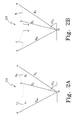
- Figure 2A depicts a first range scan 210 along the road, in which the segments a-b 1 and c 1 -d represent a sidewalk on either side of the road, segments b 1 -b 2 and c 1 -c 2 represent a curb adjacent to each sidewalk, and the middle segment b 2 -c 2 represents the road.
- Figure 2B depicts a second range scan 220 further along the road, in which the segment e-f, in between the segment b-c, represents an obstacle such as a car on the road in front of the autonomous land vehicle.
- the beam lines R 0 , R i , and R m extending from an origin O for each of range scans 210 and 220, represent the distances (ranges) from the laser scanner to the points a, i, and d .
- the angle ⁇ i is the azimuth angle of the line O- i with respect to the laser scanner reference.
- the method of the invention builds a three-dimensional road model from cumulated range scans, which are gathered by the laser scanner, and from geo-locations, which are obtained from the navigation unit.
- This three-dimensional road model which represents a ground plane, is formulated as a constrained quadratic surface.
- the inputted range scan data after being transformed into world coordinate points of the three-dimensional road model, can then be correctly classified based on heights above the ground plane.
- FIG. 3 is a functional block diagram showing a laser ranging process 300 according to the present invention for road and obstacle detection.
- range scans and GPS/INS measurements are input into a World Coordinate Transformation (WCT) unit 310, which is configured to combine the range measurement data with the navigation data to determine a coordinate transformation.
- the WCT unit 310 transforms the range measurements in a range scan, which are recorded as the azimuth angles and ranges with respect to a location of the laser scanner, to Universal Transverse Mercator (UTM) world coordinate data with respect to a reference location, e.g. , the starting point of the route.
- UTM Universal Transverse Mercator
- This transformation is a standard technique given the vehicle's UTM coordinate, a lever arm from the navigation unit to the laser scanner, and the range scan measurements.
- a distance-based accumulator 320 is configured to receive the world coordinate data from WCT unit 310.
- the accumulator 320 assembles the range scans into a variable size buffer 330 based on a specified fixed distance, which is a variable parameter depending on the expected road type. For example, a smooth road type dictates a shorter fixed distance while a rough and irregular road type requires a longer fixed distance.
- variable size buffer 330 saves a fixed distance coverage area of the range scans regardless of the speed of the vehicle. For example, as shown in Figure 1 , the distance covered, d , is kept fixed for the range scans that are saved in the buffer. The time for scanning (t 0 to t n ) and the buffer size vary. The process performed by accumulator 320 is described hereafter in further detail with respect to Figure 4 .
- ground plane estimator 340 Data from distance-based accumulator 320 and the variable size buffer 330 is fed into a quadratic ground plane estimator 340, which estimates a ground plane from a history of road measurements that are cumulated from previous range measurement scans.
- the ground plane estimation fits the road measurements into a quadratic surface with a restricted curvature.
- the range measurements sometimes can be noisy, and measurements other than that from the road may be added into the ground plane estimation as data outliers. Standard best fit methods, such as least square fit, often yield a biased estimate due to the presence of the outliers.
- the ground plane estimator 340 utilizes a modified RANSAC (RANdom SAmple Consensus) process, which is immune to outliers, to estimate the ground plane quadratic surface.
- RANSAC Random SAmple Consensus
- Data generated by the ground plane estimator 340 is input into a traversability/obstacle assessment module 350, which also is configured to receive input range scan data transformed to UTM coordinates.
- the assessment module 350 classifies the range scan data into traversable, non-traversable, and obstacle areas.
- the heights of the range scan measurements from the estimated ground plane are computed and compared with predetermined height thresholds, such as a curb threshold and an obstacle threshold. For example, heights below the curb threshold are classified as traversable such as for a road, heights above the obstacle threshold are classified as obstacles and thus non-traversable, and heights in between the two thresholds are classified as non-traversable such as for a curb.
- the height thresholds can be varied depending on the size and type of vehicle. For example, heights in between a curb threshold and an obstacle threshold can be classified as traversable when the vehicle is large enough. The height thresholds can also be ignored if necessary to avoid an obstacle ( e.g. , drive over a curb to avoid a pedestrian).
- the range scan measurements are classified into traversable, non-traversable, or obstacle areas for the autonomous vehicle, the range scan measurements are labeled in world coordinates and output to a path planner to determine a route for navigating the autonomous vehicle.
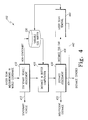
- Range scan measurements in world coordinates are received by a stationary vehicle assessment module 410, which determines whether the vehicle is stationary or moving, by comparing a current range scan with an immediately preceding range scan stored in variable size buffer 330. These two range scans will be very similar when the vehicle is stationary. One method to measure the similarity is that a sum of the absolute difference between the two range scans is less than the measurement noise.
- Another embodiment in the determination of a stationary vehicle is based on the INS input, which provides the dynamics of the vehicle, such as the velocity and the positions of the vehicle. If the vehicle is stationary, a "stationary vehicle" signal 412 is returned and no change is made to buffer 330. In addition, no new information will be output to the path planner from this stationary range scan.
- the current range scan is added to buffer 330, and the distance covered (D c ) by the range scans stored in buffer 330 is computed by a computation module 420.
- D c the distance covered by the range scans stored in buffer 330
- a computation module 420 For each range scan, a position in world coordinates is computed. This position can be the first measurement of the range scan. In such a case, no additional computation and storage are required.
- the mean or median position of the measurement in each range scan is computed.
- the distance covered in the buffer, D c can then be computed as the L2 norm between the first and last range scans in the buffer.
- a distance assessment module 430 compares a required fixed distance threshold, D thrs , with the distance covered, D c , in buffer 330. If D c is less than D thrs , then an insufficient distance signal 432 is returned. If D c is approximately equal to D thrs , then a distance covered signal 434 is returned. When D c is greater than D thrs , a distance too far signal 436 is sent to a range scan removal module 440, which removes older range scans from buffer 330 until a new distance, D c ', in buffer 330 is just larger than D thrs . A distance covered signal 442 from range scan removal module 440 is then returned.
- D thrs required fixed distance threshold
- the quadratic ground plane estimator 340 ( Figure 3 ) generates a ground plane representation.
- the estimation process then computes the constants, A, B, and C, such that the range scan measurements in the buffer best fit a plane according to equation (1).
- the constrained constants A and B can only have restricted values.
- the shape and curvature of the quadratic surface is mainly governed by these two constrained constants.
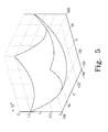
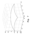
- Figures 5-7 are three-dimensional graphical representations showing the shape and curvature of quadratic surfaces.
- the quadratic surface is concave, as shown in the diagram of Figure 5 .
- the quadratic surface is convex, as shown in the diagram of Figure 6 .
- the curvature of the quadratic surface can also be determined by the values of constrained constants A and B, as shown in the diagram of Figure 7 .
- a road is not concave and obviously, a road does not resemble Figures 5 and 6 because of their high curvatures.
- the values of A and B must be constrained in order to properly represent a road surface.
- the values of constrained constants A and B will be confined to a range of values, during the ground plane estimation process.
- the range of values for A and B can be determined based on the types and construct of the road, such as the number of lanes, straight or curved road, etc. Without the knowledge of the expected road type and construct, one can restrict the values of constrained constants A and B to be small.
- the ground plane estimator utilizes a modified RANSAC process.
- Laser measurements are typically noisy, e.g. , due to wetness, roughness, scatter, and irregular reflectance of the scanned surfaces, which can be a road, other vehicles, or a sidewalk. Many outliers that are not the elements of a road are measured and collected in the buffer. In this situation, the conventional least square fit method to estimate the quadratic ground plane does not work well. Hence, the method of the invention applies a modified RANSAC process.
- the standard RANSAC process uses an iterative technique to estimate parameters of a mathematical model from a set of observed data.
- a randomly sampled population is selected from the entire population, which are the measurements of the range scans in the buffer.
- a technique such as least square fit, is used to estimate the quadratic ground plane (all the constants in equation 2).
- the error of the entire population as fitted into the estimated ground plane is computed. If the error is less than a predefined threshold or a maximum number of iterations is reached, the best ground plane estimate is outputted. If the error exceeds the threshold, the best ground plane estimate so far is kept and another iteration is exercised.
- a basic assumption of the RANSAC process is that the data contains "inliers” which are data points that can be explained by some set of model parameters, and "outliers” which are data points that do not fit the model.
- the RANSAC process also assumes that, given a set of inliers, there exists a procedure which can estimate the parameters of a model that optimally explains or fits the data. Further details regarding the RANSAC process are in an article by M. A. Fischler, R. C. Bolles, "Random Sample Consensus: A Paradigm for Model Fitting with Applications to Image Analysis and Automated Cartography," Comm. of the ACM 24: 381-395 (June 1981 ), which is incorporated herein by reference.
- the modified RANSAC process utilized in the present method changes two elements of the standard RANSAC process.
- the first change is to the definition of the best ground plane estimate.
- the best ground plane estimate is the one that has the minimum error.
- the definition of the best ground plane estimate is the one that has the minimum error and for which the constrained constant criterion is met.
- the second changed element is the sampling process.
- the entire population (all range scans) is divided into n number of bins, with each bin having range scans that cover approximately equal distance traveled. Then, range scans from each bin are randomly sampled to form the sample space for the least square fit. This sampling technique assures that the measurements are obtained from the full spectrum of the buffer for each iteration of the RANSAC process.
- the present method stores in the buffer only those measurements of the range scans that belong to the estimated ground plane. This avoids the sampling of the range scan measurements from the non-ground plane elements, which need to be rejected as outliers during the RANSAC process anyway.
- Instructions for carrying out the various process tasks, calculations, and generation of signals and other data used in the operation of the method and system of the invention can be implemented in software, firmware, or other computer readable instructions. These instructions are typically stored on any appropriate computer readable media used for storage of computer readable instructions or data structures. Such computer readable media can be any available media that can be accessed by a general purpose or special purpose computer or processor, or any programmable logic device.
- Suitable computer readable media may comprise, for example, non-volatile memory devices including semiconductor memory devices such as EPROM, EEPROM, or flash memory devices; magnetic disks such as internal hard disks or removable disks; magneto-optical disks; CDs, DVDs, or other optical storage disks; nonvolatile ROM, RAM, and other like media; or any other media that can be used to carry or store desired program code in the form of computer executable instructions or data structures. Any of the foregoing may be supplemented by, or incorporated in, specially-designed application-specific integrated circuits (ASICs) or field programmable gate arrays (FPGAs).
- ASICs application-specific integrated circuits
- FPGAs field programmable gate arrays
- the method of the invention can be implemented by computer executable instructions, such as program modules, which are executed by a processor.
- program modules include routines, programs, objects, data components, data structures, algorithms, and the like, which perform particular tasks or implement particular abstract data types.
- Computer executable instructions, associated data structures, and program modules represent examples of program code means for executing steps of the methods disclosed herein. The particular sequence of such executable instructions or associated data structures represents examples of corresponding acts for implementing the functions described in such steps.
Landscapes
- Engineering & Computer Science (AREA)
- Physics & Mathematics (AREA)
- General Physics & Mathematics (AREA)
- Computer Networks & Wireless Communication (AREA)
- Electromagnetism (AREA)
- Radar, Positioning & Navigation (AREA)
- Remote Sensing (AREA)
- Multimedia (AREA)
- Theoretical Computer Science (AREA)
- Traffic Control Systems (AREA)
- Control Of Position, Course, Altitude, Or Attitude Of Moving Bodies (AREA)
Applications Claiming Priority (1)
| Application Number | Priority Date | Filing Date | Title |
|---|---|---|---|
| US12/182,774 US8755997B2 (en) | 2008-07-30 | 2008-07-30 | Laser ranging process for road and obstacle detection in navigating an autonomous vehicle |
Publications (1)
| Publication Number | Publication Date |
|---|---|
| EP2149799A2 true EP2149799A2 (de) | 2010-02-03 |
Family
ID=41278693
Family Applications (1)
| Application Number | Title | Priority Date | Filing Date |
|---|---|---|---|
| EP09160948A Withdrawn EP2149799A2 (de) | 2008-07-30 | 2009-05-22 | Laseridentifikationsverfahren zur Straßen- und Hinderniserkennung bei der Navigation eines unabhängigen Fahrzeugs |
Country Status (2)
| Country | Link |
|---|---|
| US (1) | US8755997B2 (de) |
| EP (1) | EP2149799A2 (de) |
Cited By (5)
| Publication number | Priority date | Publication date | Assignee | Title |
|---|---|---|---|---|
| WO2014148978A1 (en) * | 2013-03-19 | 2014-09-25 | Scania Cv Ab | Control system and method for control of a vehicle in connection with detection of an obstacle |
| CN104849723A (zh) * | 2015-04-14 | 2015-08-19 | 同济大学 | 一种基于多元线阵激光雷达的模拟月表地形的识别方法 |
| WO2017186385A1 (de) * | 2016-04-29 | 2017-11-02 | Robert Bosch Gmbh | Verfahren und vorrichtung für ein kraftfahrzeug zum vergleich von umgebungskartendaten mit umgebungssensordaten zur ermittlung der passierbarkeit eines strassenobjekts |
| EP3278318A1 (de) * | 2015-03-31 | 2018-02-07 | Valeo Schalter und Sensoren GmbH | Verfahren zum bereitstellen von höheninformationen eines objekts in einem umgebungsbereich eines kraftfahrzeugs an einer kommunikationsschnittstelle, sensoreinrichtung, verarbeitungseinrichtung und kraftfahrzeug |
| IT201600114161A1 (it) * | 2016-11-11 | 2018-05-11 | Info Solution S P A | Metodo e dispositivo di pilotaggio di un veicolo semovente e relativo sistema di pilotaggio |
Families Citing this family (58)
| Publication number | Priority date | Publication date | Assignee | Title |
|---|---|---|---|---|
| DE102007026275A1 (de) * | 2007-06-05 | 2008-12-18 | General Dynamics Santa Bárbara Sistemas GmbH | Verfahren zum Verlegen einer militärischen Brücke |
| US8452053B2 (en) * | 2008-04-24 | 2013-05-28 | GM Global Technology Operations LLC | Pixel-based texture-rich clear path detection |
| US9129523B2 (en) * | 2013-05-22 | 2015-09-08 | Jaybridge Robotics, Inc. | Method and system for obstacle detection for vehicles using planar sensor data |
| US8565958B1 (en) * | 2011-06-02 | 2013-10-22 | Google Inc. | Removing extraneous objects from maps |
| US20130006482A1 (en) * | 2011-06-30 | 2013-01-03 | Ramadev Burigsay Hukkeri | Guidance system for a mobile machine |
| US8825391B1 (en) | 2011-08-04 | 2014-09-02 | Google Inc. | Building elevation maps from laser data |
| JP5741321B2 (ja) * | 2011-08-23 | 2015-07-01 | 株式会社富士通ゼネラル | 運転支援装置 |
| KR101820299B1 (ko) * | 2011-11-23 | 2018-03-02 | 삼성전자주식회사 | 3차원 데이터 영상의 계단 인식 방법 |
| US9123152B1 (en) | 2012-05-07 | 2015-09-01 | Google Inc. | Map reports from vehicles in the field |
| US9098086B2 (en) * | 2012-08-07 | 2015-08-04 | Caterpillar Inc. | Method and system for planning a turn path for a machine |
| US9052721B1 (en) | 2012-08-28 | 2015-06-09 | Google Inc. | Method for correcting alignment of vehicle mounted laser scans with an elevation map for obstacle detection |
| US8885151B1 (en) | 2012-09-04 | 2014-11-11 | Google Inc. | Condensing sensor data for transmission and processing |
| JP2014106897A (ja) * | 2012-11-29 | 2014-06-09 | Toyota Motor Corp | 通行可否判定装置 |
| US9251627B2 (en) * | 2013-03-05 | 2016-02-02 | Sears Brands, L.L.C. | Removable dashboard instrument system |
| US9305241B2 (en) * | 2013-07-29 | 2016-04-05 | Google Inc. | Systems and methods for reducing a data set |
| US9285230B1 (en) * | 2013-12-20 | 2016-03-15 | Google Inc. | Methods and systems for detecting road curbs |
| KR101632486B1 (ko) * | 2014-07-09 | 2016-06-22 | 고려대학교 산학협력단 | 레이저 거리 센서를 이용한 도로의 연석 추출 방법 및 도로의 연석 정보를 이용한 이동 로봇의 위치 측정 방법 |
| US10099615B2 (en) * | 2014-09-29 | 2018-10-16 | Ambarella, Inc. | All-round view monitoring system for a motor vehicle |
| US9494093B2 (en) | 2014-10-08 | 2016-11-15 | Ford Global Technologies, Llc | Detecting and negotiating a climbable obstacle in a vehicle |
| US9969325B2 (en) | 2015-09-15 | 2018-05-15 | International Business Machines Corporation | Projected surface markings |
| US10071748B2 (en) * | 2015-09-17 | 2018-09-11 | Sony Corporation | System and method for providing driving assistance to safely overtake a vehicle |
| JP6462544B2 (ja) * | 2015-09-17 | 2019-01-30 | 株式会社東芝 | 推定装置、方法及びプログラム |
| US9946259B2 (en) | 2015-12-18 | 2018-04-17 | Raytheon Company | Negative obstacle detector |
| US10386480B1 (en) | 2016-02-02 | 2019-08-20 | Waymo Llc | Radar based mapping and localization for autonomous vehicles |
| US9849883B2 (en) * | 2016-05-04 | 2017-12-26 | Ford Global Technologies, Llc | Off-road autonomous driving |
| US10101746B2 (en) * | 2016-08-23 | 2018-10-16 | Delphi Technologies, Inc. | Automated vehicle road model definition system |
| EP3736537A1 (de) | 2016-10-11 | 2020-11-11 | Mobileye Vision Technologies Ltd. | Navigation eines fahrzeugs auf der grundlage einer erkannten farhzeug |
| JP6637400B2 (ja) * | 2016-10-12 | 2020-01-29 | 本田技研工業株式会社 | 車両制御装置 |
| WO2018132632A1 (en) | 2017-01-13 | 2018-07-19 | Diversey, Inc. | Three-dimensional scanning using fixed planar distance sensors |
| SE541527C2 (en) * | 2017-01-19 | 2019-10-29 | Scania Cv Ab | Method and control unit for avoiding that an autonomus vehicle get stuck in a soft soil segment |
| US10598790B2 (en) | 2017-02-17 | 2020-03-24 | Essential Products, Inc. | Modular light detection and ranging device of a vehicular navigation system |
| DE102017204306A1 (de) * | 2017-03-15 | 2018-09-20 | Zf Friedrichshafen Ag | Anordnung und Verfahren zur Bestimmung eines Steigungssignals in einem Fahrzeug |
| JP6579144B2 (ja) * | 2017-03-28 | 2019-09-25 | 株式会社Soken | 障害物検知装置 |
| US10176596B1 (en) * | 2017-07-06 | 2019-01-08 | GM Global Technology Operations LLC | Calibration verification methods for autonomous vehicle operations |
| JP6796041B2 (ja) * | 2017-09-07 | 2020-12-02 | 日立建機株式会社 | 安全運転支援装置 |
| ES3042160T3 (en) * | 2017-11-28 | 2025-11-18 | Elta Systems Ltd | Failure detection in an autonomous vehicle |
| IL260821B2 (en) * | 2018-07-26 | 2023-11-01 | Israel Aerospace Ind Ltd | Failure detection in an autonomous vehicle |
| US10766487B2 (en) | 2018-08-13 | 2020-09-08 | Denso International America, Inc. | Vehicle driving system |
| CN109271944B (zh) * | 2018-09-27 | 2021-03-12 | 百度在线网络技术(北京)有限公司 | 障碍物检测方法、装置、电子设备、车辆及存储介质 |
| GB2578108A (en) | 2018-10-15 | 2020-04-22 | Atlantic Inertial Systems Ltd | A navigation system |
| CN109788030B (zh) * | 2018-12-17 | 2021-08-03 | 北京百度网讯科技有限公司 | 无人车数据处理方法、装置、系统及存储介质 |
| US11560153B2 (en) | 2019-03-07 | 2023-01-24 | 6 River Systems, Llc | Systems and methods for collision avoidance by autonomous vehicles |
| US11828848B2 (en) | 2019-03-14 | 2023-11-28 | Aeva, Inc. | Velocity estimation using doppler per point LiDAR systems |
| US11914368B2 (en) | 2019-08-13 | 2024-02-27 | Zoox, Inc. | Modifying limits on vehicle dynamics for trajectories |
| US11407409B2 (en) | 2019-08-13 | 2022-08-09 | Zoox, Inc. | System and method for trajectory validation |
| US11458965B2 (en) | 2019-08-13 | 2022-10-04 | Zoox, Inc. | Feasibility validation for vehicle trajectory selection |
| US11397434B2 (en) | 2019-08-13 | 2022-07-26 | Zoox, Inc. | Consistency validation for vehicle trajectory selection |
| EP4013654B1 (de) * | 2019-08-13 | 2025-12-31 | Zoox, Inc. | Änderung der grenzwerte für die fahrzeugdynamik bei strecken |
| US11042025B2 (en) | 2019-09-20 | 2021-06-22 | Raytheon Company | Optical data communication using micro-electro-mechanical system (MEMS) micro-mirror arrays |
| US11584377B2 (en) * | 2019-11-21 | 2023-02-21 | Gm Cruise Holdings Llc | Lidar based detection of road surface features |
| US11539131B2 (en) | 2020-08-24 | 2022-12-27 | Raytheon Company | Optical true time delay (TTD) device using microelectrical-mechanical system (MEMS) micromirror arrays (MMAS) that exhibit tip/tilt/piston (TTP) actuation |
| US11837840B2 (en) | 2020-09-01 | 2023-12-05 | Raytheon Company | MEMS micro-mirror array laser beam steerer for simultaneous illumination of multiple tracked targets |
| US11815676B2 (en) | 2020-09-17 | 2023-11-14 | Raytheon Company | Active pushbroom imaging system using a micro-electro-mechanical system (MEMS) micro-mirror array (MMA) |
| US11522331B2 (en) | 2020-09-23 | 2022-12-06 | Raytheon Company | Coherent optical beam combination using micro-electro-mechanical system (MEMS) micro-mirror arrays (MMAs) that exhibit tip/tilt/piston (TTP) actuation |
| US12372658B2 (en) | 2020-10-12 | 2025-07-29 | Raytheon Company | Negative obstacle detector using micro-electro-mechanical system (MEMS) micro-mirror array (MMA) beam steering |
| US12066574B2 (en) | 2021-01-15 | 2024-08-20 | Raytheon Company | Optical system for object detection and location using a Micro-Electro-Mechanical System (MEMS) Micro-Mirror Array (MMA) beamsteering device |
| US12384410B2 (en) | 2021-03-05 | 2025-08-12 | The Research Foundation For The State University Of New York | Task-motion planning for safe and efficient urban driving |
| US11851051B2 (en) * | 2021-07-28 | 2023-12-26 | Toyota Motor Engineering & Manufacturing North America, Inc. | System and method for detecting an object in a turning alert zone of a vehicle |
Family Cites Families (30)
| Publication number | Priority date | Publication date | Assignee | Title |
|---|---|---|---|---|
| US4740085A (en) | 1986-02-18 | 1988-04-26 | Northrop Corporation | Scale factor stability control |
| US5050423A (en) | 1989-12-04 | 1991-09-24 | Motorola, Inc. | Multi-variable sensor calibration |
| US5680306A (en) * | 1990-02-05 | 1997-10-21 | Caterpillar Inc. | System, and method for enabling a vehicle to track a path |
| JPH04238216A (ja) | 1991-01-23 | 1992-08-26 | Sumitomo Electric Ind Ltd | ジャイロのスケールファクタの算出方法 |
| JP2501010B2 (ja) | 1993-10-25 | 1996-05-29 | インターナショナル・ビジネス・マシーンズ・コーポレイション | 移動ロボットの誘導装置 |
| US7359782B2 (en) * | 1994-05-23 | 2008-04-15 | Automotive Technologies International, Inc. | Vehicular impact reactive system and method |
| US7630806B2 (en) | 1994-05-23 | 2009-12-08 | Automotive Technologies International, Inc. | System and method for detecting and protecting pedestrians |
| US5999866A (en) | 1996-11-05 | 1999-12-07 | Carnegie Mellon University | Infrastructure independent position determining system |
| US6002983A (en) | 1997-08-27 | 1999-12-14 | Delphi Technologies, Inc. | Angle extent estimation method for a motor vehicle object detection system |
| JP2882788B1 (ja) | 1998-04-20 | 1999-04-12 | 長野計器株式会社 | 自己校正型センサ |
| US6298288B1 (en) | 1998-12-16 | 2001-10-02 | Hughes Electronics Corp. | Autonomous gyro scale factor and misalignment calibration |
| US6754370B1 (en) | 2000-08-14 | 2004-06-22 | The Board Of Trustees Of The Leland Stanford Junior University | Real-time structured light range scanning of moving scenes |
| JP3893912B2 (ja) | 2001-07-18 | 2007-03-14 | 株式会社日立製作所 | 車両制御装置 |
| JP3880837B2 (ja) | 2001-11-02 | 2007-02-14 | 富士重工業株式会社 | 車外監視装置 |
| US6778924B2 (en) | 2001-11-06 | 2004-08-17 | Honeywell International Inc. | Self-calibrating inertial measurement system method and apparatus |
| US6615117B2 (en) | 2001-11-13 | 2003-09-02 | The Boeing Company | Attitude determination system and method with outer-loop gyro scale-factor non-linearity calibration |
| US6679702B1 (en) | 2001-12-18 | 2004-01-20 | Paul S. Rau | Vehicle-based headway distance training system |
| US6728608B2 (en) | 2002-08-23 | 2004-04-27 | Applied Perception, Inc. | System and method for the creation of a terrain density model |
| DE10330011B4 (de) | 2003-07-03 | 2005-05-12 | Eads Deutschland Gmbh | Verfahren zur Hinderniserkennung und Geländeklassifikation |
| JP4052650B2 (ja) * | 2004-01-23 | 2008-02-27 | 株式会社東芝 | 障害物検出装置、方法及びプログラム |
| US7643966B2 (en) * | 2004-03-10 | 2010-01-05 | Leica Geosystems Ag | Identification of 3D surface points using context-based hypothesis testing |
| US7272474B1 (en) | 2004-03-31 | 2007-09-18 | Carnegie Mellon University | Method and system for estimating navigability of terrain |
| KR100954621B1 (ko) * | 2005-02-23 | 2010-04-27 | 파나소닉 전공 주식회사 | 자동운전차량 및 평면 장애물인식방법 |
| US8050863B2 (en) * | 2006-03-16 | 2011-11-01 | Gray & Company, Inc. | Navigation and control system for autonomous vehicles |
| EP2078286A1 (de) * | 2006-10-30 | 2009-07-15 | Tele Atlas B.V. | Verfahren und vorrichtung zur erfassung von objekten unter terrestrischen mobilen kartierungsdaten |
| WO2008068542A1 (en) | 2006-12-04 | 2008-06-12 | Nokia Corporation | Auto-calibration method for sensors and auto-calibrating sensor arrangement |
| US7739896B2 (en) | 2007-03-15 | 2010-06-22 | Northrop Grumman Guidance And Electronics Company, Inc. | Self-calibration of scale factor for dual resonator class II coriolis vibratory gyros |
| US7995055B1 (en) * | 2007-05-25 | 2011-08-09 | Google Inc. | Classifying objects in a scene |
| US8446468B1 (en) * | 2007-06-19 | 2013-05-21 | University Of Southern California | Moving object detection using a mobile infrared camera |
| US8126642B2 (en) | 2008-10-24 | 2012-02-28 | Gray & Company, Inc. | Control and systems for autonomously driven vehicles |
-
2008
- 2008-07-30 US US12/182,774 patent/US8755997B2/en active Active
-
2009
- 2009-05-22 EP EP09160948A patent/EP2149799A2/de not_active Withdrawn
Non-Patent Citations (1)
| Title |
|---|
| M. A. FISCHLER; R. C. BOLLES: "Random Sample Consensus: A Paradigm for Model Fitting with Applications to Image Analysis and Automated Cartography", COMM. OF THE ACM, vol. 24, June 1981 (1981-06-01), pages 381 - 395 |
Cited By (7)
| Publication number | Priority date | Publication date | Assignee | Title |
|---|---|---|---|---|
| WO2014148978A1 (en) * | 2013-03-19 | 2014-09-25 | Scania Cv Ab | Control system and method for control of a vehicle in connection with detection of an obstacle |
| EP3278318A1 (de) * | 2015-03-31 | 2018-02-07 | Valeo Schalter und Sensoren GmbH | Verfahren zum bereitstellen von höheninformationen eines objekts in einem umgebungsbereich eines kraftfahrzeugs an einer kommunikationsschnittstelle, sensoreinrichtung, verarbeitungseinrichtung und kraftfahrzeug |
| CN104849723A (zh) * | 2015-04-14 | 2015-08-19 | 同济大学 | 一种基于多元线阵激光雷达的模拟月表地形的识别方法 |
| WO2017186385A1 (de) * | 2016-04-29 | 2017-11-02 | Robert Bosch Gmbh | Verfahren und vorrichtung für ein kraftfahrzeug zum vergleich von umgebungskartendaten mit umgebungssensordaten zur ermittlung der passierbarkeit eines strassenobjekts |
| US10889271B2 (en) | 2016-04-29 | 2021-01-12 | Robert Bosch Gmbh | Method and device for a motor vehicle for comparing surrounding area map data to surrounding area sensor data to determine the passability of a road object |
| IT201600114161A1 (it) * | 2016-11-11 | 2018-05-11 | Info Solution S P A | Metodo e dispositivo di pilotaggio di un veicolo semovente e relativo sistema di pilotaggio |
| WO2018087703A1 (en) * | 2016-11-11 | 2018-05-17 | Info Solution S.P.A. | Method and device for driving a self-moving vehicle and related driving system |
Also Published As
| Publication number | Publication date |
|---|---|
| US8755997B2 (en) | 2014-06-17 |
| US20100030473A1 (en) | 2010-02-04 |
Similar Documents
| Publication | Publication Date | Title |
|---|---|---|
| US8755997B2 (en) | Laser ranging process for road and obstacle detection in navigating an autonomous vehicle | |
| US8364334B2 (en) | System and method for navigating an autonomous vehicle using laser detection and ranging | |
| US11703879B2 (en) | All weather autonomously driven vehicles | |
| Sun et al. | A 3D LiDAR data-based dedicated road boundary detection algorithm for autonomous vehicles | |
| US20080033645A1 (en) | Pobabilistic methods for mapping and localization in arbitrary outdoor environments | |
| CN109791052B (zh) | 使用数字地图对点云的数据点进行分类的方法和系统 | |
| Levinson et al. | Robust vehicle localization in urban environments using probabilistic maps | |
| Hata et al. | Feature detection for vehicle localization in urban environments using a multilayer LIDAR | |
| AU2012314067B2 (en) | Localising transportable apparatus | |
| Levinson et al. | Map-based precision vehicle localization in urban environments. | |
| JP2022106924A (ja) | 自律的な自己位置推定のためのデバイス及び方法 | |
| US11842430B2 (en) | Methods and systems for ground segmentation using graph-cuts | |
| CN112074885A (zh) | 车道标志定位 | |
| Pannen et al. | HD map change detection with a boosted particle filter | |
| US12392619B2 (en) | Vehicle localization system and method | |
| CN105488243A (zh) | 交叉口结构的联合概率建模及推断 | |
| Liebner et al. | Crowdsourced hd map patches based on road model inference and graph-based slam | |
| Hervieu et al. | Road side detection and reconstruction using LIDAR sensor | |
| Vora et al. | Aerial imagery based lidar localization for autonomous vehicles | |
| Levinson | Automatic laser calibration, mapping, and localization for autonomous vehicles | |
| JP2007303842A (ja) | 車両位置推定装置及び地図情報作成装置 | |
| Burger et al. | Unstructured Road SLAM using Map Predictive Road Tracking. | |
| Dean et al. | Terrain-based road vehicle localization on multi-lane highways | |
| AU2017254915B2 (en) | Information processing system and information processing method | |
| Wang et al. | Simultaneous Localization and Mapping with Road Markings Identified from LiDAR Intensity |
Legal Events
| Date | Code | Title | Description |
|---|---|---|---|
| PUAI | Public reference made under article 153(3) epc to a published international application that has entered the european phase |
Free format text: ORIGINAL CODE: 0009012 |
|
| 17P | Request for examination filed |
Effective date: 20090522 |
|
| AK | Designated contracting states |
Kind code of ref document: A2 Designated state(s): AT BE BG CH CY CZ DE DK EE ES FI FR GB GR HR HU IE IS IT LI LT LU LV MC MK MT NL NO PL PT RO SE SI SK TR |
|
| STAA | Information on the status of an ep patent application or granted ep patent |
Free format text: STATUS: THE APPLICATION HAS BEEN WITHDRAWN |
|
| 18W | Application withdrawn |
Effective date: 20100429 |