EP2149724A1 - Reduction gear device - Google Patents
Reduction gear device Download PDFInfo
- Publication number
- EP2149724A1 EP2149724A1 EP08764618A EP08764618A EP2149724A1 EP 2149724 A1 EP2149724 A1 EP 2149724A1 EP 08764618 A EP08764618 A EP 08764618A EP 08764618 A EP08764618 A EP 08764618A EP 2149724 A1 EP2149724 A1 EP 2149724A1
- Authority
- EP
- European Patent Office
- Prior art keywords
- gear
- internal
- support element
- external
- crank
- Prior art date
- Legal status (The legal status is an assumption and is not a legal conclusion. Google has not performed a legal analysis and makes no representation as to the accuracy of the status listed.)
- Granted
Links
Images


Classifications
-
- F—MECHANICAL ENGINEERING; LIGHTING; HEATING; WEAPONS; BLASTING
- F16—ENGINEERING ELEMENTS AND UNITS; GENERAL MEASURES FOR PRODUCING AND MAINTAINING EFFECTIVE FUNCTIONING OF MACHINES OR INSTALLATIONS; THERMAL INSULATION IN GENERAL
- F16H—GEARING
- F16H1/00—Toothed gearings for conveying rotary motion
- F16H1/28—Toothed gearings for conveying rotary motion with gears having orbital motion
- F16H1/32—Toothed gearings for conveying rotary motion with gears having orbital motion in which the central axis of the gearing lies inside the periphery of an orbital gear
-
- F—MECHANICAL ENGINEERING; LIGHTING; HEATING; WEAPONS; BLASTING
- F16—ENGINEERING ELEMENTS AND UNITS; GENERAL MEASURES FOR PRODUCING AND MAINTAINING EFFECTIVE FUNCTIONING OF MACHINES OR INSTALLATIONS; THERMAL INSULATION IN GENERAL
- F16H—GEARING
- F16H57/00—General details of gearing
- F16H57/12—Arrangements for adjusting or for taking-up backlash not provided for elsewhere
-
- F—MECHANICAL ENGINEERING; LIGHTING; HEATING; WEAPONS; BLASTING
- F16—ENGINEERING ELEMENTS AND UNITS; GENERAL MEASURES FOR PRODUCING AND MAINTAINING EFFECTIVE FUNCTIONING OF MACHINES OR INSTALLATIONS; THERMAL INSULATION IN GENERAL
- F16H—GEARING
- F16H57/00—General details of gearing
- F16H57/12—Arrangements for adjusting or for taking-up backlash not provided for elsewhere
- F16H2057/121—Arrangements for adjusting or for taking-up backlash not provided for elsewhere using parallel torque paths and means to twist the two path against each other
Definitions
- the present invention relates to a reduction gear system including a plurality of reduction gears.
- Patent Document 1 Japanese Patent No. 3414880
- This reduction gear system is a reduction gear system including a first reduction gear having a first internal gear, a first external gear which meshes with the first internal gear, a first crank element which engages with the first external gear so as to cause the first external gear to perform an eccentric motion and a first support element for supporting the first crank element rotatably and a second reduction gear having a second internal gear, a second external gear which meshes with the second internal gear, a second crank element which engages with the second external gear so as to cause the second external gear to perform an eccentric motion and a second support element for supporting the second crank element rotatably, wherein the first support element and the second support element are fixed to each other.
- both the input shafts are fixed so as not to rotate relative to each other.
- the invention provides a reduction gear system which is made to reduce backlash between meshing gears, that is, internal gears and external gears of a first reduction gear and a second reduction gear by work to preload the internal gears and the external gears of the first reduction gear and the second reduction gear in a simple fashion from outer circumferences of the first reduction gear and the second reduction gear.
- a reduction gear system including a first reduction gear having a first internal gear, a first external gear which meshes with the first internal gear, a first crank element which engages with the first external gear so as to cause the first external gear to perform an eccentric motion and a first support element for supporting the first crank element rotatably and a second reduction gear having a second internal gear, a second external gear which meshes with the second internal gear, a second crank element which engages with the second external gear so as to cause the second external gear to perform an eccentric motion and a second support element for supporting the second crank element rotatably, wherein the first crank element and the second crank element are connected to each other, wherein the first support element and the second support element or the first internal gear and the second internal gear are fixed to each other, and wherein the first internal gear and the second internal gear or the first support element and the second support element are fixed to each other under a state that the first internal gear and the second internal gear or the first support element and the second support element are
- a reduction gear system wherein a pair of bearings are disposed between the second internal gear and the second support element to straddle the second external gear.
- a reduction gear system including a spur gear which is connected to the second crank element and an input gear which meshes with the spur gear.
- a reduction gear system including a first reduction gear having a first internal gear, a first external gear which meshes with the first internal gear, a first crank element which engages with the first external gear so as to cause the first external gear to perform an eccentric motion and a first support element for supporting the first crank element rotatably and a second reduction gear having a second internal gear, a second external gear which meshes with the second internal gear, a second crank element which engages with the second external gear so as to cause the second external gear to perform an eccentric motion and a second support element for supporting the second crank element rotatably, the reduction gear system including a spur gear which is connected to the second crank element and an input gear which meshes with the spur gear, wherein the first crank element and the second crank element are connected to each other, wherein the first support element and the second support element are fixed to each other, and wherein the first internal gear and the second internal gear are fixed to each other.
- a reduction gear system including a first reduction gear having a first internal gear, a first external gear which meshes with the first internal gear, a first crank element which engages with the first external gear so as to cause the first external gear to perform an eccentric motion and a first support element for supporting the first crank element rotatably and a second reduction gear having a second internal gear, a second external gear which meshes with the second internal gear, a second crank element which engages with the second external gear so as to cause the second external gear to perform an eccentric motion and a second support element for supporting the second crank element rotatably, the reduction gear system having; a first spur gear which is connected to the first crank element; a second spur gear which is connected to the second crank element; and an input gear which meshes with the first spur gear and the second spur gear, wherein the first support element and the second support element are fixed to each other, and wherein the first internal gear and the second internal gear are fixed to each other.
- a reduction gear system wherein a pair of bearings are disposed between the second internal gear and the second support element to straddle the second external gear. Additionally, there is provided a reduction gear system, wherein the first internal gear and the second internal gear are fixed under a state that the first internal gear and the second internal gear are rotated in opposite directions relative to each other. In addition, there is provided a reduction gear system, wherein the first support element and the second support element are fixed under a state that the first support element and the second support element are rotated in opposite directions relative to each other.
- backlash between the internal gears and the external gears of the first reduction gear and the second reduction gear can be reduced by work to simply preload the internal gears and the external gears of the first reduction gear and the second reduction gear from outer circumferences of the first reduction gear and the second reduction gear. Consequently, the reduction gear system in which backlash is reduced can be provided simply and inexpensively by the simple work.
- the pair of bearings are disposed only between the second internal gear and the second support element to straddle the second external gear but no bearing is disposed between the first internal gear and the first support element, the reduction gear system can be provided which is inexpensive.
- the first reduction gear and the second reduction gear are used to be disposed side by side in the axial direction, the first support element and the second support element are fixed to each other, the first internal gear and the second internal gear are fixed to each other, and the input gear is caused to mesh with the first spur gear connected to the first crank element and the second spur gear connected to the second crank element simultaneously, an input shaft can be made common. Consequently, the number of parts can be reduced, thereby making it possible to provide the reduction gear system which is inexpensive.
- the reduction gear system can be provided which is inexpensive. Additionally, according to the invention, backlash between the internal gears and the external gears of the first reduction gear and the second reduction gear can be reduced by work to simply preload the respective meshing gears from outer circumferences of the first reduction gear and the second reduction gear. Consequently, the reduction gear system in which backlash is reduced can be provided simply and inexpensively by the simple work.
- a reduction gear system 100 is made up of a first reduction gear 30 and a second reduction gear 40
- the first reduction gear 30 includes a first internal toothed element 2 having a plurality of pins 1 on an inner circumference thereof as internal teeth, a pair of first external gears 4 having pluralities of external teeth 3 which mesh with the internal teeth 1, a plurality of crank elements 6 which engage with the first external gears 4 so as to cause the first external gears 4 to perform eccentric motions, and a first support element 7 which supports the first crank elements 6 rotatably.
- the plurality of pins 1, which function as the internal teeth, and the first internal toothed element 2 are configured into a first internal gear.
- the first support element 7 is made up of a support main body 9 on which a pillar portion 8 is formed to penetrate through the first external gears 4 and a disc element 10, and the support main body 9 and the disc element 10 are positioned relative to each other with a pin 11.
- the number of internal teeth 1 is larger by one or two than the number of external teeth 3.
- the second reduction gear 40 includes a second internal toothed element 13 having a plurality of pins 12 on an inner circumference thereof as internal teeth, a pair of second external gears 15 having pluralities of external teeth 14 which mesh with the internal gears 12, a plurality of second crank elements 17 which engage with the second external gears 15 so as to cause the second external gears 15 to perform eccentric motions, and a second support element 18 which supports the second crank elements 17 rotatably.
- the plurality of pins 12, which function as the internal teeth, and the second internal toothed element 13 are configured into a second internal gear.
- the second support element 18 is made up of a support main body 20 on which a pillar portion 19 is formed to penetrate through the second external gears 15 and a disc element 21, and the support main body 20 and the disc element 21 are positioned relative to each other with a pin 22.
- the number of internal teeth 12 is made larger by one or two than the number of external teeth 14.
- the speed reducing ratios of the first reduction gear 30 and the second reduction gear 40 are set identical with each other.
- the first crank elements 6 and the second crank elements 17 are spline connected to each other via a coupling 23 so as to rotate together, and the first support element 7 and the second support element 18 are fixed to each other with a bolt 24, and the first internal toothed element 2 and the second internal toothed element 13 are connected to each other with bolts 25 under a state that the first internal toothed element 2 and the second internal toothed element 13 are rotated in opposite directions relative to each other so as to push on each other (under a state that the first internal toothed element 2 and the second internal toothed element 13 can each be moved by looseness therein and the internal tooth pins 1 of the first internal toothed element 2 and the external teeth 3 of the first external gears 4 and the internal tooth pins 12 of the second internal toothed element 13 and the external teeth 14 of the second external gears 15 are preloaded).
- a positioning taper pin 45 is inserted into a lower hole 46 provided in the first internal toothed element 2 and the second internal toothed element 13 so that the preloaded state cannot be released in an ensured fashion.
- the lower hole 46 may be machined beforehand or may be machined under a state that the first internal toothed element 2 and the second internal toothed element 13 are rotated in the opposite directions relative to each other so as to push on each other.
- the taper pin 45 can be inserted thereinto in a tightly fitting fashion.
- the positioning taper pin 45 does not necessarily have to be used.
- bolts or machine screws may be screwed into towards outer circumferential connecting surfaces of the first internal toothed element 2 and the second internal toothed element 13 from outer circumferences of the first internal toothed element 2 and the second internal toothed element 13.
- the first internal toothed element 2 and the second internal toothed element 13 are positioned to each other in a radiating direction (a radial direction) by a socket and smooth fitting at a stepped portion 47. Abutment surfaces of the first internal toothed element 2 and the second internal toothed element 13 are sealed by an O ring 48.
- a pair of bearings 26 are disposed between the second internal toothed element 13 and the second support element 18 to straddle the second external gears 15.
- a motor flange 50 is fixed to the first internal toothed element 2 with the bolts 25.
- a motor 51 is fixed to the motor flange 50 with bolts 27. Consequently, the motor 51 is fixed to the first internal toothed element 2 via the motor flange 50.
- the rotation of the motor 51 is transmitted to the second crank elements 17 from an input shaft 52 of the motor 51 via a spur gear mechanism 60, and the second support element 18 of the second reduction gear 40 constitutes a rotational output.
- the spur gear mechanism 60 is made up of an input shaft 62 which has a spur gear portion 61 having a small diameter and which is fixed to the motor shaft 5 with a key 53 and a spur gear 63 having a large diameter which meshes with the small-diameter spur gear portion and which is connected to the second crank elements 17 and constitutes front-stage speed reducing mechanism.
- a pair of bearings 31 are disposed between the first crank elements 6 and the first support element 7.
- a bearing 32 is disposed between respective crank portions 5 and the respective first external gears 4.
- a pair of bearings 41 are disposed between the second crank elements 17 and the second support element 18.
- a bearing 42 is disposed between respective crank portions 16 and the respective second external gears 14.
- An oil seal 43 is disposed between the inner circumference of the second internal toothed element 13 and the support main body 20.
- first crank elements 6 and the second crank elements 17 are spline connected to each other via the coupling 23, the first crank elements 6 and the second crank elements 17 may be connected together with a key or any other means.
- Embodiment 1 Since the speed reducing function by the first reduction gear 30 and the second reduction gear 40 is known, the speed reducing function will be described briefly.
- the rotation of the motor shaft 52 is transmitted to the second crank elements 17 and the first crank elements 6 via the spur gear mechanism 60, and rotation with a reduced speed is taken out from the second support element 18 and the first support element 7 which are fixed to each other.
- a reduction gear system 100 is made up of a first reduction gear 30 and a second reduction gear 40.
- the first reduction gear 30 includes a first internal toothed element 2 having a plurality of pins 1 as internal teeth on an inner circumference thereof, a pair of first external gears 4, a plurality of first crank elements 6 and a first support element 7.
- the plurality of pins 1 functioning as internal teeth and the first internal toothed element 2 constitute a first internal gear.
- the second reduction gear 40 includes a second internal toothed element 13 having a plurality of pins 12 as internal teeth on an inner circumference thereof, a pair of second external gears 15, a plurality of second crank elements 17 and a second support element 18.
- the plurality of pins 12 functioning as internal teeth and the first internal toothed element 13 constitute a second internal gear.
- the first crank elements 6 and the second crank elements 17 are spline connected together via a coupling 23 to rotate together, the first support element 7 and the second support element 18 are fixed to each other with bolts 24, and the first internal toothed element 2 and the second internal toothed element 13 are fixed to each other with bolts 25 under a state that the first internal toothed element 2 and the second internal toothed element 13 are rotated in opposite directions relative to each other.
- a pair of bearings 26 are disposed between the second internal toothed element 13 and the second support element 18 to straddle the second external gears 15.
- a motor flange 50 is fixed to the first internal toothed element 2 with the bolts 25.
- A, motor 51 is fixed to the motor flange 50 with bolts (not shown). Consequently, the motor 51 is fixed to the first internal toothed element 2 via the motor flange 50.
- the rotation of the motor 51 is transmitted to the first crank elements 6 from an output shaft 52 of the motor via a spur gear mechanism 60, and the second support element 18 of the second reduction gear 40 constitutes a rotational output.
- a shaft portion 64 of an intermediate spur gear 63 is supported rotatably on the motor flange 50 by a bearing 65.
- the spur gear mechanism 60 is made up of a spur gear 61 having a small diameter and fixed to the motor shaft 52, the intermediate spur gear 63 which meshes with the small-diameter spur gear 61, and a spur gear 62 having a large diameter which meshes with the intermediate spur gear 63 and which is connected to the first crank elements 6.
- a center spur gear 66 is supported rotatably on the first support element 7 and the motor flange 50 by a bearing 67 and meshes with spur gears (not shown) which are connected to the other crank elements.
- a large hollow hole is provided at a center of each of the motor flange 50, the first support element 7, the first external gears 4, the second support element 18 and the second external gears 15.
- a hollow protection tube 70 is inserted into the motor flange 50, the first support element 7, the first external gears 4, the second support element 18, and the second external gears 15 and is fixed to the second support element 18 with bolts 71. Pipings and cables can be passed through the hollow space of the protection tube 70.
- Embodiment 2 Since the speed reducing function by the first reduction gear 30 and the second reduction gear 40 is known, the speed reducing function will be described briefly.
- the rotation of the motor shaft 52 is transmitted to the second crank elements 17 and the first crank elements 6 via the spur gear mechanism 60, and rotation with a reduced speed is taken out from the second support element 18 and the first support element 7 which are fixed to each other.
- the backlash can be suppressed to on the order of 0.3 arcminute or smaller.
- pipings and cables can be passed through the hollow space in the protection tube 70.
- a reduction gear system 100 is made up of a center crank-type first reduction gear 30 and a center crank-type second reduction gear 40.
- the first reduction gear 30 includes a first internal toothed element 2 having a plurality of pins 1 as internal teeth on an inner circumference thereof, three first external gears 4, a first crank element 6 and a first support element 7.
- the plurality of pins 1 functioning as internal teeth and the first internal tootled element 2 constitute a first internal gear.
- the second reduction gear 40 includes a second internal toothed element 13 having a plurality of pins 12 as internal teeth on an inner circumference thereof, three second external gears 15, a second crank element 17 and a second support element 18.
- the plurality of pins 12 functioning as internal teeth and the second internal toothed element 13 constitute a second internal gear.
- the first crank element 6 and the second crank element 17 are spline connected to each other via a coupling 23 to rotate together, the first support element 7 and the second support element 18 are fixed together with bolts 24, and the first internal toothed element 2 and the second internal toothed element 13 are fixed to each other with bolts 25 under a state that the first internal toothed element 2 and the second internal toothed element 13 are rotated in opposite directions relative to each other.
- a pair of bearings 26 are disposed between the second internal toothed element 13 and the second support element 18 to straddle the second external gears 15.
- the rotation of a motor (not shown) is inputted to male splines 66 of the first support element 7.
- Rotation with a reduced speed is outputted from the first internal toothed element 2 and the second internal toothed element 13 or the first support element 7 and the second support element 18.
- a large hollow hole 68 is provided at a center of each of the first crank element 6 and the second crank element 17. Pipings and cables can be passed through the hollow holes 68.
- the first crank element 6 and the second crank element 17 are supported rotatably on the first support element 7 and the second support element 18 by pairs of bearings 70, respectively.
- Oil seals 69 are disposed individually between the second internal toothed element 13 and the second support element 18 and between the first internal toothed element 2 and the first support element 7.
- screws 71 may be screwed in towards outer circumferential connecting surfaces of the first internal toothed element 2 and the second internal toothed element 13 from outer circumferences of the first internal toothed element 2 and the second internal toothed element 13.
- Embodiment 3 Since the speed reducing function by the first reduction gear 30 and the second reduction gear 40 is known, the speed reducing function will be described briefly.
- the first internal toothed element 2 and the second internal toothed element 13 are fixed, rotation with a reduced speed is taken out from the second support element 18 and the first support element 7 which are fixed to each other.
- the backlash can be suppressed to on the order of 0,3 arcminute or smaller.
- a reduction gear system 100 is made up of a first reduction gear 30 and a second reduction gear 40.
- the first reduction gear 30 includes a first internal toothed element 2 having a plurality of pins 1 on an inner circumference thereof as internal teeth, a pair of first external gears 4 having pluralities of external teeth 3 which mesh with the internal teeth 1, a plurality of crank elements 6 which engage with the first external gears 4 so as to cause the first external gears 4 to perform eccentric motions, and a first support element 7 which supports the first crank elements 6 rotatably.
- the plurality of pins 1, which function as the internal teeth, and the first internal toothed element 2 are configured into a first internal gear.
- the first support element 7 is made up of a support main body 9 on which a pillar portion 8 is formed to penetrate through the first external gears 4 and a disc element 10, and the support main body 9 and the disc element 10 are positioned relative to each other with a pin 11.
- the number of internal teeth 1 is larger by one or two than the number of external teeth 3.
- the second reduction gear 40 includes a second internal toothed element 13 having a plurality of pins 12 on an inner circumference thereof as internal teeth, a pair of second external gears 15 having pluralities of external teeth 14 which mesh with the internal gears 12, a plurality of second crank elements 17 which engage with the second external gears 15 so as to cause the second external gears 15 to perform eccentric motions, and a second support element 18 which supports the second crank elements 17 rotatably.
- the plurality of pins 12, which function as the internal teeth, and the second internal toothed element 13 are configured into a second internal gear.
- the second support element 18 is made up of a support main body 20 on which a pillar portion 19 is formed to penetrate through the second external gears 15 and a disc element 21, and the support main body 20 and the disc element 21 are positioned relative to each other with a pin 22.
- the number of internal teeth 12 is made larger by one or two than the number of external teeth 14.
- the speed reducing ratios of the first reduction gear 30 and the second reduction gear 40 are set identical with each other.
- first spur gear 33 which is spline connected to the first crank elements to rotate together
- second spur gear 44 which is spline connected to the second crank elements to rotate together
- a single input shaft 62 having a spur gear portion 61, and the spur gear portion 61 of the input shaft 62 is caused to mesh with the first spur gear 33 and the second spur gear 44.
- the number of teeth of the spur gear portion 61 is made smaller than the numbers of teeth of the first spur gear 33 and the second spur gear 44 and constitutes a front-state speed reducing mechanism.
- the first support element 7 and the second support element 18 are fixed to each other with a bolt 24, and the first internal toothed element 2 and the second internal toothed element 13 are connected to each other with bolts 25 under a state that the first internal toothed element 2 and the second internal toothed element 13 are rotated in opposite directions relative to each other so as to push on each other (such that the first internal toothed element 2 and the second internal toothed element 13 can each be moved by looseness therein and the internal tooth pins 1 of the first internal toothed element 2 and the external teeth 3 of the first external gears 4 and the internal tooth pins 12 of the second internal toothed element 13 and the external teeth 14 of the second external gears 15 are preloaded).
- a positioning taper pin 45 is inserted into a lower hole 46 provided in the first internal toothed element 2 and the second internal toothed element 13 so that the preloaded state cannot be released in an ensured fashion.
- the lower hole 46 may be machined beforehand or may be machined under a state that the first internal toothed element 2 and the second internal toothed element 13 are rotated in the opposite directions relative to each other so as to push on each other.
- the taper pin 45 can be inserted thereinto in a tightly fitting fashion.
- the positioning taper pin 45 does not necessarily have to be used.
- bolts or machine screws may be screwed in towards outer circumferential connecting surfaces of the first internal toothed element 2 and the second internal toothed element 13 from outer circumferences of the first internal toothed element 2 and the second internal toothed element 13.
- the first internal toothed element 2 and the second internal toothed element 13 are positioned to each other in a radiating direction (a radial direction) by a socket and smooth fitting at a stepped portion 47. Abutment surfaces of the first internal toothed element 2 and the second internal toothed element 13 are sealed by an O-ring 48.
- a hole 65 formed in a rotating central portion of a crank shaft of the second support element 18 is closed by a lid 68.
- a pair of bearings 26 are disposed between the second internal toothed element 13 and the second support element 18 to straddle the second external gears 15.
- a motor flange 50 is fixed to the first Internal toothed element 2 with the bolts 25.
- a motor 51 is fixed to the motor flange 50 with bolts 27. Consequently, the motor 51 is fixed to the first internal toothed element 2 via the motor flange 50.
- the input shaft 62 is connected to a rotational shaft 52 of the motor with a key means 53 so that the rotational shaft 52 of the motor and the input shaft 62 rotate together relative to each other, and the second support element 18 of the second reduction gear constitutes a rotational output.
- a pair of bearings 31 are disposed between the first crank elements 6 and the first support element 7.
- a bearing 32 is disposed between respective crank portions 5 and the respective first external gears 4.
- a pair of bearings 41 are disposed between the second crank elements 17 and the second support element 18.
- a bearing 42 is disposed between respective crank portions 16 and the respective second external gears 14.
- An oil seal 43 is disposed between the inner circumference of the second internal toothed element 13 and the support main body 20.
- Embodiment 4 Since the speed reducing function by the first reduction gear 30 and the second reduction gear 40 is known, the speed reducing function will be described briefly.
- the rotation of the motor shaft 52 is transmitted from the spur gear portion 61 of the input shaft 62 to the second crank elements 17 and the first crank elements 6 via the spur gears 33 and 44, and rotation with a reduced speed is taken out from the second support element 18 and the first support element 7 which are fixed to each other.
- first internal gear and the second internal gear may be connected to each other, and the first support element and the second support element may be fixed to each other under a state that the first support element and the second support element are rotated in opposite directions relative to each other.
- the support main body 9 of the first support element and the disc element 21 of the second support element may be made into an integral unit.
- the first internal gear 2 and the second internal gear 13 may be made into an integral unit.
- This invention can be applied to a reduction system including a plurality of reduction gears or a plurality of speed reducing mechanisms.
Landscapes
- Engineering & Computer Science (AREA)
- General Engineering & Computer Science (AREA)
- Mechanical Engineering (AREA)
- Retarders (AREA)
- Gear Transmission (AREA)
- Gears, Cams (AREA)
Abstract
Description
- The present invention relates to a reduction gear system including a plurality of reduction gears.
- As a related-art reduction gear system, there is, for example, a reduction gear system described in
Patent Document 1 below. - Patent Document 1: Japanese Patent No.
3414880 - This reduction gear system is a reduction gear system including a first reduction gear having a first internal gear, a first external gear which meshes with the first internal gear, a first crank element which engages with the first external gear so as to cause the first external gear to perform an eccentric motion and a first support element for supporting the first crank element rotatably and a second reduction gear having a second internal gear, a second external gear which meshes with the second internal gear, a second crank element which engages with the second external gear so as to cause the second external gear to perform an eccentric motion and a second support element for supporting the second crank element rotatably, wherein the first support element and the second support element are fixed to each other.
In addition, in a frame and an interior of a motor base, by fastening a Shepin ring which is a frictional fastening member which is interposed between both input shafts of the first reduction gear and the second reduction gear in a position where an arbitrary initial input torque is added to both the input shafts by rotating the input shaft of the first reduction gear relative to the input shaft of the second reduction gear with a fastening plate, both the input shafts are fixed so as not to rotate relative to each other. - In this related-art reduction gear system, in the frame and the interior of the motor base, by selecting the interference of the fastening plate or the Shepin ring appropriately, the backlash of a drive unit is made to be reduced easily. Consequently, in order to reduce the backlash, the fastening plate and the Shepin ring are necessary, and this has served to make the construction of the reduction gear system complex, worsen the working properties of the same system and increase the production costs thereof.
- In view of the problem, the invention provides a reduction gear system which is made to reduce backlash between meshing gears, that is, internal gears and external gears of a first reduction gear and a second reduction gear by work to preload the internal gears and the external gears of the first reduction gear and the second reduction gear in a simple fashion from outer circumferences of the first reduction gear and the second reduction gear.
- According to a first aspect of the invention, there is provided a reduction gear system including a first reduction gear having a first internal gear, a first external gear which meshes with the first internal gear, a first crank element which engages with the first external gear so as to cause the first external gear to perform an eccentric motion and a first support element for supporting the first crank element rotatably and a second reduction gear having a second internal gear, a second external gear which meshes with the second internal gear, a second crank element which engages with the second external gear so as to cause the second external gear to perform an eccentric motion and a second support element for supporting the second crank element rotatably, wherein the first crank element and the second crank element are connected to each other, wherein the first support element and the second support element or the first internal gear and the second internal gear are fixed to each other, and wherein the first internal gear and the second internal gear or the first support element and the second support element are fixed to each other under a state that the first internal gear and the second internal gear or the first support element and the second support element are rotated in opposite directions relative to each other.
In addition, there is provided a reduction gear system wherein a pair of bearings are disposed between the second internal gear and the second support element to straddle the second external gear.
Additionally, there is provided a reduction gear system including a spur gear which is connected to the second crank element and an input gear which meshes with the spur gear.
In addition, there is provided a reduction gear system including a first reduction gear having a first internal gear, a first external gear which meshes with the first internal gear, a first crank element which engages with the first external gear so as to cause the first external gear to perform an eccentric motion and a first support element for supporting the first crank element rotatably and a second reduction gear having a second internal gear, a second external gear which meshes with the second internal gear, a second crank element which engages with the second external gear so as to cause the second external gear to perform an eccentric motion and a second support element for supporting the second crank element rotatably, the reduction gear system including a spur gear which is connected to the second crank element and an input gear which meshes with the spur gear, wherein the first crank element and the second crank element are connected to each other, wherein the first support element and the second support element are fixed to each other, and wherein the first internal gear and the second internal gear are fixed to each other. - According to another aspect of the invention, there is provided a reduction gear system including a first reduction gear having a first internal gear, a first external gear which meshes with the first internal gear, a first crank element which engages with the first external gear so as to cause the first external gear to perform an eccentric motion and a first support element for supporting the first crank element rotatably and a second reduction gear having a second internal gear, a second external gear which meshes with the second internal gear, a second crank element which engages with the second external gear so as to cause the second external gear to perform an eccentric motion and a second support element for supporting the second crank element rotatably, the reduction gear system having;
a first spur gear which is connected to the first crank element; a second spur gear which is connected to the second crank element; and an input gear which meshes with the first spur gear and the second spur gear, wherein the first support element and the second support element are fixed to each other, and wherein the first internal gear and the second internal gear are fixed to each other.
In addition, there is provided a reduction gear system, wherein a pair of bearings are disposed between the second internal gear and the second support element to straddle the second external gear.
Additionally, there is provided a reduction gear system, wherein the first internal gear and the second internal gear are fixed under a state that the first internal gear and the second internal gear are rotated in opposite directions relative to each other.
In addition, there is provided a reduction gear system, wherein the first support element and the second support element are fixed under a state that the first support element and the second support element are rotated in opposite directions relative to each other. - According to the invention, backlash between the internal gears and the external gears of the first reduction gear and the second reduction gear can be reduced by work to simply preload the internal gears and the external gears of the first reduction gear and the second reduction gear from outer circumferences of the first reduction gear and the second reduction gear. Consequently, the reduction gear system in which backlash is reduced can be provided simply and inexpensively by the simple work.
In addition, according to the invention, since the pair of bearings are disposed only between the second internal gear and the second support element to straddle the second external gear but no bearing is disposed between the first internal gear and the first support element, the reduction gear system can be provided which is inexpensive. - According to the invention, since the first reduction gear and the second reduction gear are used to be disposed side by side in the axial direction, the first support element and the second support element are fixed to each other, the first internal gear and the second internal gear are fixed to each other, and the input gear is caused to mesh with the first spur gear connected to the first crank element and the second spur gear connected to the second crank element simultaneously, an input shaft can be made common. Consequently, the number of parts can be reduced, thereby making it possible to provide the reduction gear system which is inexpensive.
Additionally, according to the invention, since the pair of bearings are disposed only between the second internal toothed element and the second support element to straddle the second external gear but no bearing is disposed between the first internal toothed element and the first support element, the reduction gear system can be provided which is inexpensive.
Additionally, according to the invention, backlash between the internal gears and the external gears of the first reduction gear and the second reduction gear can be reduced by work to simply preload the respective meshing gears from outer circumferences of the first reduction gear and the second reduction gear. Consequently, the reduction gear system in which backlash is reduced can be provided simply and inexpensively by the simple work. -
- [
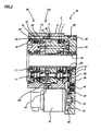
Fig. 1 ] An overall view of a reduction gear system ofEmbodiment 1 according to the invention with a motor attached thereto. - [
Fig. 2 ] An overall view of a reduction gear system ofEmbodiment 2 according to the invention with a motor attached thereto. - [
Fig. 3 ] An overall view of a reduction gear system of Embodiment 3 according to the invention. - [
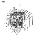
Fig. 4 ] An overall view of a reduction gear system of Embodiment 4 according to the invention. - Hereinafter,
Embodiment 1 of the invention will be described based on the drawing.
InFig. 1 , areduction gear system 100 is made up of afirst reduction gear 30 and asecond reduction gear 40, Thefirst reduction gear 30 includes a firstinternal toothed element 2 having a plurality ofpins 1 on an inner circumference thereof as internal teeth, a pair of first external gears 4 having pluralities of external teeth 3 which mesh with theinternal teeth 1, a plurality ofcrank elements 6 which engage with the first external gears 4 so as to cause the first external gears 4 to perform eccentric motions, and afirst support element 7 which supports thefirst crank elements 6 rotatably. The plurality ofpins 1, which function as the internal teeth, and the firstinternal toothed element 2 are configured into a first internal gear. Thefirst support element 7 is made up of a support main body 9 on which apillar portion 8 is formed to penetrate through the first external gears 4 and adisc element 10, and the support main body 9 and thedisc element 10 are positioned relative to each other with apin 11. The number ofinternal teeth 1 is larger by one or two than the number of external teeth 3.
Thesecond reduction gear 40 includes a secondinternal toothed element 13 having a plurality ofpins 12 on an inner circumference thereof as internal teeth, a pair of secondexternal gears 15 having pluralities ofexternal teeth 14 which mesh with theinternal gears 12, a plurality ofsecond crank elements 17 which engage with the secondexternal gears 15 so as to cause the secondexternal gears 15 to perform eccentric motions, and asecond support element 18 which supports thesecond crank elements 17 rotatably. The plurality ofpins 12, which function as the internal teeth, and the secondinternal toothed element 13 are configured into a second internal gear. Thesecond support element 18 is made up of a supportmain body 20 on which apillar portion 19 is formed to penetrate through the secondexternal gears 15 and a disc element 21, and the supportmain body 20 and the disc element 21 are positioned relative to each other with a pin 22. The number ofinternal teeth 12 is made larger by one or two than the number ofexternal teeth 14.
In addition, the speed reducing ratios of thefirst reduction gear 30 and thesecond reduction gear 40 are set identical with each other.
Thefirst crank elements 6 and thesecond crank elements 17 are spline connected to each other via acoupling 23 so as to rotate together, and thefirst support element 7 and thesecond support element 18 are fixed to each other with abolt 24, and the firstinternal toothed element 2 and the secondinternal toothed element 13 are connected to each other withbolts 25 under a state that the firstinternal toothed element 2 and the secondinternal toothed element 13 are rotated in opposite directions relative to each other so as to push on each other (under a state that the firstinternal toothed element 2 and the secondinternal toothed element 13 can each be moved by looseness therein and theinternal tooth pins 1 of the firstinternal toothed element 2 and the external teeth 3 of the first external gears 4 and theinternal tooth pins 12 of the secondinternal toothed element 13 and theexternal teeth 14 of the secondexternal gears 15 are preloaded). In addition, apositioning taper pin 45 is inserted into alower hole 46 provided in the firstinternal toothed element 2 and the secondinternal toothed element 13 so that the preloaded state cannot be released in an ensured fashion. Thelower hole 46 may be machined beforehand or may be machined under a state that the firstinternal toothed element 2 and the secondinternal toothed element 13 are rotated in the opposite directions relative to each other so as to push on each other. In the case of the lower hole being machined beforehand, in the event that a taper hole having a slightly larger diameter than thelower hole 46 is machined further on thelower hole 46 when the firstinternal toothed element 2 and the secondinternal toothed element 13 are rotated in the opposite directions relative to each other so as to push on each other, thetaper pin 45 can be inserted thereinto in a tightly fitting fashion.
In the event that the firstinternal toothed element 2 and the secondinternal toothed element 13 are fixed to each other strongly and rigidly with thebolts 25 so that the preloaded state cannot be released, thepositioning taper pin 45 does not necessarily have to be used. In addition, in place of using thepositioning taper pin 45, bolts or machine screws may be screwed into towards outer circumferential connecting surfaces of the firstinternal toothed element 2 and the secondinternal toothed element 13 from outer circumferences of the firstinternal toothed element 2 and the secondinternal toothed element 13.
The firstinternal toothed element 2 and the secondinternal toothed element 13 are positioned to each other in a radiating direction (a radial direction) by a socket and smooth fitting at a stepped portion 47. Abutment surfaces of the firstinternal toothed element 2 and the secondinternal toothed element 13 are sealed by anO ring 48. - A pair of
bearings 26 are disposed between the secondinternal toothed element 13 and thesecond support element 18 to straddle the secondexternal gears 15. Amotor flange 50 is fixed to the firstinternal toothed element 2 with thebolts 25. Amotor 51 is fixed to themotor flange 50 withbolts 27. Consequently, themotor 51 is fixed to the firstinternal toothed element 2 via themotor flange 50. The rotation of themotor 51 is transmitted to thesecond crank elements 17 from aninput shaft 52 of themotor 51 via aspur gear mechanism 60, and thesecond support element 18 of thesecond reduction gear 40 constitutes a rotational output. Thespur gear mechanism 60 is made up of aninput shaft 62 which has aspur gear portion 61 having a small diameter and which is fixed to themotor shaft 5 with a key 53 and aspur gear 63 having a large diameter which meshes with the small-diameter spur gear portion and which is connected to thesecond crank elements 17 and constitutes front-stage speed reducing mechanism.
A pair ofbearings 31 are disposed between thefirst crank elements 6 and thefirst support element 7. Abearing 32 is disposed betweenrespective crank portions 5 and the respective first external gears 4. A pair ofbearings 41 are disposed between thesecond crank elements 17 and thesecond support element 18. A bearing 42 is disposed betweenrespective crank portions 16 and the respective secondexternal gears 14. Anoil seal 43 is disposed between the inner circumference of the secondinternal toothed element 13 and the supportmain body 20. InEmbodiment 1, although the first crankelements 6 and the second crankelements 17 are spline connected to each other via thecoupling 23, the first crankelements 6 and the second crankelements 17 may be connected together with a key or any other means. - Next, the function of
Embodiment 1 will be described. Since the speed reducing function by thefirst reduction gear 30 and thesecond reduction gear 40 is known, the speed reducing function will be described briefly.
When the first internaltoothed element 2 and the second internaltoothed element 13 are fixed, the rotation of themotor shaft 52 is transmitted to the second crankelements 17 and the first crankelements 6 via thespur gear mechanism 60, and rotation with a reduced speed is taken out from thesecond support element 18 and thefirst support element 7 which are fixed to each other.
Here, in the event that theinternal teeth 1 of the first internaltoothed element 2 and the external teeth 3 of the first external gears 4 and theinternal teeth 12 of the second internaltoothed element 13 and theexternal teeth 14 of the secondexternal gears 15 are not preloaded, backlash at those meshing teeth portions is on the order of 0.5 arcminute at best. InEmbodiment 1, however, since the first internal toothed element and the second internal toothed element are fixed together under a state that the first internal toothed element and the second internal toothed element are rotated in the opposite directions relative to each other, so that the internal teeth and the external teeth are preloaded, the backlash can be suppressed to on the order of 0.3 arcminute or smaller. - Hereinafter,
Embodiment 2 of the invention will be described based on the drawing. Like reference numerals will be given to like constituent elements to those ofEmbodiment 1, and the description thereof will be made briefly.
InFig. 2 , areduction gear system 100 is made up of afirst reduction gear 30 and asecond reduction gear 40. Thefirst reduction gear 30 includes a first internaltoothed element 2 having a plurality ofpins 1 as internal teeth on an inner circumference thereof, a pair of first external gears 4, a plurality of first crankelements 6 and afirst support element 7. The plurality ofpins 1 functioning as internal teeth and the first internaltoothed element 2 constitute a first internal gear.
Thesecond reduction gear 40 includes a second internaltoothed element 13 having a plurality ofpins 12 as internal teeth on an inner circumference thereof, a pair of secondexternal gears 15, a plurality of second crankelements 17 and asecond support element 18. The plurality ofpins 12 functioning as internal teeth and the first internaltoothed element 13 constitute a second internal gear.
The first crankelements 6 and the second crankelements 17 are spline connected together via acoupling 23 to rotate together, thefirst support element 7 and thesecond support element 18 are fixed to each other withbolts 24, and the first internaltoothed element 2 and the second internaltoothed element 13 are fixed to each other withbolts 25 under a state that the first internaltoothed element 2 and the second internaltoothed element 13 are rotated in opposite directions relative to each other. - A pair of
bearings 26 are disposed between the second internaltoothed element 13 and thesecond support element 18 to straddle the second external gears 15. Amotor flange 50 is fixed to the first internaltoothed element 2 with thebolts 25. A,motor 51 is fixed to themotor flange 50 with bolts (not shown). Consequently, themotor 51 is fixed to the first internaltoothed element 2 via themotor flange 50.
The rotation of themotor 51 is transmitted to the first crankelements 6 from anoutput shaft 52 of the motor via aspur gear mechanism 60, and thesecond support element 18 of thesecond reduction gear 40 constitutes a rotational output.
Ashaft portion 64 of anintermediate spur gear 63 is supported rotatably on themotor flange 50 by abearing 65. Thespur gear mechanism 60 is made up of aspur gear 61 having a small diameter and fixed to themotor shaft 52, theintermediate spur gear 63 which meshes with the small-diameter spur gear 61, and aspur gear 62 having a large diameter which meshes with theintermediate spur gear 63 and which is connected to the first crankelements 6. Acenter spur gear 66 is supported rotatably on thefirst support element 7 and themotor flange 50 by abearing 67 and meshes with spur gears (not shown) which are connected to the other crank elements.
A large hollow hole is provided at a center of each of themotor flange 50, thefirst support element 7, the first external gears 4, thesecond support element 18 and the second external gears 15.
Ahollow protection tube 70 is inserted into themotor flange 50, thefirst support element 7, the first external gears 4, thesecond support element 18, and the secondexternal gears 15 and is fixed to thesecond support element 18 withbolts 71. Pipings and cables can be passed through the hollow space of theprotection tube 70. - Next, the function of
Embodiment 2 will be described. Since the speed reducing function by thefirst reduction gear 30 and thesecond reduction gear 40 is known, the speed reducing function will be described briefly.
When the first internaltoothed element 2 and the second internaltoothed element 13 are fixed, the rotation of themotor shaft 52 is transmitted to the second crankelements 17 and the first crankelements 6 via thespur gear mechanism 60, and rotation with a reduced speed is taken out from thesecond support element 18 and thefirst support element 7 which are fixed to each other.
Here, as withEmbodiment 1, inEmbodiment 2, as well, since the internal teeth and the external teeth are preloaded, the backlash can be suppressed to on the order of 0.3 arcminute or smaller. In addition, pipings and cables can be passed through the hollow space in theprotection tube 70. - Hereinafter, Embodiment 3 of the invention will be described based on the drawing. Like reference numerals will be given to like constituent elements to those of
Embodiment 1, and the description thereof will be made briefly.
InFig, 3 , areduction gear system 100 is made up of a center crank-typefirst reduction gear 30 and a center crank-typesecond reduction gear 40. Thefirst reduction gear 30 includes a first internaltoothed element 2 having a plurality ofpins 1 as internal teeth on an inner circumference thereof, three first external gears 4, afirst crank element 6 and afirst support element 7. The plurality ofpins 1 functioning as internal teeth and the first internal tootledelement 2 constitute a first internal gear.
Thesecond reduction gear 40 includes a second internaltoothed element 13 having a plurality ofpins 12 as internal teeth on an inner circumference thereof, three secondexternal gears 15, asecond crank element 17 and asecond support element 18. The plurality ofpins 12 functioning as internal teeth and the second internaltoothed element 13 constitute a second internal gear.
Thefirst crank element 6 and thesecond crank element 17 are spline connected to each other via acoupling 23 to rotate together, thefirst support element 7 and thesecond support element 18 are fixed together withbolts 24, and the first internaltoothed element 2 and the second internaltoothed element 13 are fixed to each other withbolts 25 under a state that the first internaltoothed element 2 and the second internaltoothed element 13 are rotated in opposite directions relative to each other. - A pair of
bearings 26 are disposed between the second internaltoothed element 13 and thesecond support element 18 to straddle the second external gears 15. The rotation of a motor (not shown) is inputted tomale splines 66 of thefirst support element 7. Rotation with a reduced speed is outputted from the first internaltoothed element 2 and the second internaltoothed element 13 or thefirst support element 7 and thesecond support element 18. A largehollow hole 68 is provided at a center of each of thefirst crank element 6 and thesecond crank element 17. Pipings and cables can be passed through the hollow holes 68.
Thefirst crank element 6 and thesecond crank element 17 are supported rotatably on thefirst support element 7 and thesecond support element 18 by pairs ofbearings 70, respectively. Oil seals 69 are disposed individually between the second internaltoothed element 13 and thesecond support element 18 and between the first internaltoothed element 2 and thefirst support element 7.
In place of using a positioning taper pin, screws 71 may be screwed in towards outer circumferential connecting surfaces of the first internaltoothed element 2 and the second internaltoothed element 13 from outer circumferences of the first internaltoothed element 2 and the second internaltoothed element 13. - Next, the function of Embodiment 3 will be described. Since the speed reducing function by the
first reduction gear 30 and thesecond reduction gear 40 is known, the speed reducing function will be described briefly.
When the first internaltoothed element 2 and the second internaltoothed element 13 are fixed, rotation with a reduced speed is taken out from thesecond support element 18 and thefirst support element 7 which are fixed to each other. Here, as withEmbodiment 1, in Embodiment 3, as well, since the internal teeth and the external teeth are preloaded, the backlash can be suppressed to on the order of 0,3 arcminute or smaller. - Hereinafter, Embodiment 4 of the invention will be described based on the drawing. Like reference numerals will be given to like constituent elements to those of
Embodiment 1, and the description thereof will be made briefly.
InFig. 4 , areduction gear system 100 is made up of afirst reduction gear 30 and asecond reduction gear 40. Thefirst reduction gear 30 includes a first internaltoothed element 2 having a plurality ofpins 1 on an inner circumference thereof as internal teeth, a pair of first external gears 4 having pluralities of external teeth 3 which mesh with theinternal teeth 1, a plurality of crankelements 6 which engage with the first external gears 4 so as to cause the first external gears 4 to perform eccentric motions, and afirst support element 7 which supports the first crankelements 6 rotatably. The plurality ofpins 1, which function as the internal teeth, and the first internaltoothed element 2 are configured into a first internal gear.
Thefirst support element 7 is made up of a support main body 9 on which apillar portion 8 is formed to penetrate through the first external gears 4 and adisc element 10, and the support main body 9 and thedisc element 10 are positioned relative to each other with apin 11. The number ofinternal teeth 1 is larger by one or two than the number of external teeth 3.
Thesecond reduction gear 40 includes a second internaltoothed element 13 having a plurality ofpins 12 on an inner circumference thereof as internal teeth, a pair of secondexternal gears 15 having pluralities ofexternal teeth 14 which mesh with theinternal gears 12, a plurality of second crankelements 17 which engage with the secondexternal gears 15 so as to cause the secondexternal gears 15 to perform eccentric motions, and asecond support element 18 which supports the second crankelements 17 rotatably. The plurality ofpins 12, which function as the internal teeth, and the second internaltoothed element 13 are configured into a second internal gear.
Thesecond support element 18 is made up of a supportmain body 20 on which apillar portion 19 is formed to penetrate through the secondexternal gears 15 and a disc element 21, and the supportmain body 20 and the disc element 21 are positioned relative to each other with a pin 22. The number ofinternal teeth 12 is made larger by one or two than the number ofexternal teeth 14. The speed reducing ratios of thefirst reduction gear 30 and thesecond reduction gear 40 are set identical with each other.
There are provided a first spur gear 33 which is spline connected to the first crank elements to rotate together, asecond spur gear 44 which is spline connected to the second crank elements to rotate together, and asingle input shaft 62 having aspur gear portion 61, and thespur gear portion 61 of theinput shaft 62 is caused to mesh with the first spur gear 33 and thesecond spur gear 44. The number of teeth of thespur gear portion 61 is made smaller than the numbers of teeth of the first spur gear 33 and thesecond spur gear 44 and constitutes a front-state speed reducing mechanism.
Thefirst support element 7 and thesecond support element 18 are fixed to each other with abolt 24, and the first internaltoothed element 2 and the second internaltoothed element 13 are connected to each other withbolts 25 under a state that the first internaltoothed element 2 and the second internaltoothed element 13 are rotated in opposite directions relative to each other so as to push on each other (such that the first internaltoothed element 2 and the second internaltoothed element 13 can each be moved by looseness therein and the internal tooth pins 1 of the first internaltoothed element 2 and the external teeth 3 of the first external gears 4 and the internal tooth pins 12 of the second internaltoothed element 13 and theexternal teeth 14 of the secondexternal gears 15 are preloaded). In addition, apositioning taper pin 45 is inserted into alower hole 46 provided in the first internaltoothed element 2 and the second internaltoothed element 13 so that the preloaded state cannot be released in an ensured fashion.
Thelower hole 46 may be machined beforehand or may be machined under a state that the first internaltoothed element 2 and the second internaltoothed element 13 are rotated in the opposite directions relative to each other so as to push on each other. In the case of the lower hole being machined beforehand, in the event that a taper hole having a slightly larger diameter than thelower hole 46 is machined further on thelower hole 46 when the first internaltoothed element 2 and the second internaltoothed element 13 are rotated in the opposite directions relative to each other so as to push on each other, thetaper pin 45 can be inserted thereinto in a tightly fitting fashion. In the event that the first internaltoothed element 2 and the second internaltoothed element 13 are fixed to each other strongly and rigidly with thebolts 25 so that the preloaded state cannot be released, thepositioning taper pin 45 does not necessarily have to be used.
In addition, in place of using thepositioning taper pin 45, bolts or machine screws may be screwed in towards outer circumferential connecting surfaces of the first internaltoothed element 2 and the second internaltoothed element 13 from outer circumferences of the first internaltoothed element 2 and the second internaltoothed element 13.
The first internaltoothed element 2 and the second internaltoothed element 13 are positioned to each other in a radiating direction (a radial direction) by a socket and smooth fitting at a stepped portion 47. Abutment surfaces of the first internaltoothed element 2 and the second internaltoothed element 13 are sealed by an O-ring 48. Ahole 65 formed in a rotating central portion of a crank shaft of thesecond support element 18 is closed by alid 68. - A pair of
bearings 26 are disposed between the second internaltoothed element 13 and thesecond support element 18 to straddle the second external gears 15. Amotor flange 50 is fixed to the first Internaltoothed element 2 with thebolts 25. Amotor 51 is fixed to themotor flange 50 withbolts 27. Consequently, themotor 51 is fixed to the first internaltoothed element 2 via themotor flange 50. Theinput shaft 62 is connected to arotational shaft 52 of the motor with a key means 53 so that therotational shaft 52 of the motor and theinput shaft 62 rotate together relative to each other, and thesecond support element 18 of the second reduction gear constitutes a rotational output.
A pair ofbearings 31 are disposed between the first crankelements 6 and thefirst support element 7. Abearing 32 is disposed between respective crankportions 5 and the respective first external gears 4. A pair ofbearings 41 are disposed between the second crankelements 17 and thesecond support element 18. A bearing 42 is disposed between respective crankportions 16 and the respective second external gears 14. Anoil seal 43 is disposed between the inner circumference of the second internaltoothed element 13 and the supportmain body 20. - Next, the function of Embodiment 4 will be described. Since the speed reducing function by the
first reduction gear 30 and thesecond reduction gear 40 is known, the speed reducing function will be described briefly.
When the first internaltoothed element 2 and the second internaltoothed element 13 are fixed, the rotation of themotor shaft 52 is transmitted from thespur gear portion 61 of theinput shaft 62 to the second crankelements 17 and the first crankelements 6 via the spur gears 33 and 44, and rotation with a reduced speed is taken out from thesecond support element 18 and thefirst support element 7 which are fixed to each other.
Here, in the event that theinternal teeth 1 of the first internaltoothed element 2 and the external teeth 3 of the first external gears 4, theinternal teeth 12 of the second internaltoothed element 13 and theexternal teeth 14 of the secondexternal gears 15, and the first spur gear 33 and thespur gear portion 61 of theinput shaft 62 which are connected to the first crank elements as the front-stage speed reducing mechanism and thefirst spur gear 44 and thespur gear portion 61 of theinput shaft 62 which are connected to the second crank element are not preloaded, backlash at meshing teeth portions between the internal teeth and the external teeth is on the order of 0.5 arcminute at best, and backlash at meshing teeth portions between the spur gear portions is on the order of 0.4 arcminute at best, resulting in a total backlash of the order of 1.0 to 0.9 arcminute.
In this embodiment, however, since the first internal toothed element and the second internal toothed element are connected and fixed together under a state that the first internal toothed element and the second internal toothed element are rotated in the opposite directions relative to each other, so that the internal teeth and the external teeth are preloaded, backlash at meshing teeth portions of the internal teeth and the external teeth can be suppressed to on the order of 0.3 arcminute or smaller, and backlash at meshing teeth portions between the spur gear portions can be suppressed to 0.2 arcminute or smaller, resulting in a total backlash of the order of 0.5 arcminute or smaller.
In addition, in this embodiment, while the first support element and the second support element are fixed to each other and the first internal gear and the second internal gear are fixed to each other under a state that the first internal gear and the second internal gear are rotated in the opposite directions relative to each other, in this embodiment, the first internal gear and the second internal gear may be connected to each other, and the first support element and the second support element may be fixed to each other under a state that the first support element and the second support element are rotated in opposite directions relative to each other.
In addition, in the event that the first support element and the second support element are fixed to each other and the first internal gear and the second internal gear are fixed to each other under a state that the first internal gear and the second internal gear are rotated in the opposite directions relative to each other, in this embodiment, the support main body 9 of the first support element and the disc element 21 of the second support element may be made into an integral unit. In addition, in the event that the first internal gear and the second internal gear are connected to each other, and the first support element and the second support element are fixed to each other under a state that the first support element and the second support element are rotated in opposite directions relative to each other, in this embodiment, the firstinternal gear 2 and the secondinternal gear 13 may be made into an integral unit. - This invention can be applied to a reduction system including a plurality of reduction gears or a plurality of speed reducing mechanisms.
Claims (8)
- A reduction gear system comprising a first reduction gear having a first internal gear, a first external gear which meshes with the first internal gear, a first crank element which engages with the first external gear so as to cause the first external gear to perform an eccentric motion and a first support element for supporting the first crank element rotatably and a second reduction gear having a second internal gear, a second external gear which meshes with the second internal gear, a second crank element which engages with the second external gear so as to cause the second external gear to perform an eccentric motion and a second support element for supporting the second crank element rotatably, wherein
the first crank element and the second crank element are connected to each other, wherein the first support element and the second support element or the first internal gear and the second internal gear are fixed to each other, and wherein the first internal gear and the second internal gear or the first support element and the second support element are fixed to each other under a state that the first internal gear and the second internal gear or the first support element and the second support element are rotated in opposite directions relative to each other. - A reduction gear system as set forth in Claim 1, wherein
a pair of bearings are disposed between the second internal gear and the second support element to straddle the second external gear. - A reduction gear system as set forth in Claim 1, comprising a spur gear which is connected to the second crank element and an input gear which meshes with the spur gear.
- A reduction gear system comprising a first reduction gear having a first internal gear, a first external gear which meshes with the first internal gear, a first crank element which engages with the first external gear so as to cause the first external gear to perform an eccentric motion and a first support element for supporting the first crank element rotatably and a second reduction gear having a second internal gear, a second external gear which meshes with the second internal gear, a second crank element which engages with the second external gear so as to cause the second external gear to perform an eccentric motion and a second support element for supporting the second crank element rotatably, wherein the reduction gear system further comprising a spur gear which is connected to the second crank element and an input gear which meshes with the spur gear, wherein the first crank element and the second crank element are connected to each other, wherein the first support element and the second support element are fixed to each other, and wherein the first internal gear and the second internal gear are fixed to each other.
- A reduction gear system comprising a first reduction gear having a first internal gear, a first external gear which meshes with the first internal gear, a first crank element which engages with the first external gear so as to cause the first external gear to perform an eccentric motion and a first support element for supporting the first crank element rotatably and a second reduction gear having a second internal gear, a second external gear which meshes with the second internal gear, a second crank element which engages with the second external gear so as to cause the second external gear to perform an eccentric motion and a second support element for supporting the second crank element rotatably, wherein the reduction gear system having a first spur gear which is connected to the first crank element, a second spur gear which is connected to the second crank element, and an input gear which meshes with the first spur gear and the second spur gear, wherein the first support element and the second support element are fixed to each other, and wherein the first internal gear and the second internal gear are fixed to each other.
- A reduction gear system as set forth in Claim 5, wherein
a pair of bearings are disposed between the second internal gear and the second support element to straddle the second external gear, - A reduction gear system as set forth in Claim 5, wherein
the first internal gear and the second internal gear are fixed under a state that the first internal gear and the second internal gear are rotated in opposite directions relative to each other. - A reduction gear system as set forth in Claim 5, wherein
the first support element and the second support element are fixed under a state that the first support element and the second support element are rotated in opposite directions relative to each other.
Applications Claiming Priority (3)
| Application Number | Priority Date | Filing Date | Title |
|---|---|---|---|
| JP2007136391 | 2007-05-23 | ||
| JP2007136390 | 2007-05-23 | ||
| PCT/JP2008/059572 WO2008146748A1 (en) | 2007-05-23 | 2008-05-23 | Reduction gear device |
Publications (3)
| Publication Number | Publication Date |
|---|---|
| EP2149724A1 true EP2149724A1 (en) | 2010-02-03 |
| EP2149724A4 EP2149724A4 (en) | 2010-07-21 |
| EP2149724B1 EP2149724B1 (en) | 2013-05-15 |
Family
ID=40074996
Family Applications (1)
| Application Number | Title | Priority Date | Filing Date |
|---|---|---|---|
| EP08764618.8A Active EP2149724B1 (en) | 2007-05-23 | 2008-05-23 | Reduction gear device |
Country Status (4)
| Country | Link |
|---|---|
| EP (1) | EP2149724B1 (en) |
| JP (1) | JP5401707B2 (en) |
| CN (1) | CN101680511B (en) |
| WO (1) | WO2008146748A1 (en) |
Cited By (12)
| Publication number | Priority date | Publication date | Assignee | Title |
|---|---|---|---|---|
| CN103206496A (en) * | 2013-04-17 | 2013-07-17 | 范巨新 | Automatic transmission capable of transmitting power by aid of shaft and plungers |
| CN104033542A (en) * | 2013-03-07 | 2014-09-10 | 鸿富锦精密工业(深圳)有限公司 | Cycloidal-pin wheel decelerating mechanism |
| US9365105B2 (en) | 2013-10-11 | 2016-06-14 | Delbert Tesar | Gear train and clutch designs for multi-speed hub drives |
| US9657813B2 (en) | 2014-06-06 | 2017-05-23 | Delbert Tesar | Modified parallel eccentric rotary actuator |
| US9862263B2 (en) | 2013-03-01 | 2018-01-09 | Delbert Tesar | Multi-speed hub drive wheels |
| US9879760B2 (en) | 2002-11-25 | 2018-01-30 | Delbert Tesar | Rotary actuator with shortest force path configuration |
| US9915319B2 (en) | 2014-09-29 | 2018-03-13 | Delbert Tesar | Compact parallel eccentric rotary actuator |
| US10414271B2 (en) | 2013-03-01 | 2019-09-17 | Delbert Tesar | Multi-speed hub drive wheels |
| US10422387B2 (en) | 2014-05-16 | 2019-09-24 | Delbert Tesar | Quick change interface for low complexity rotary actuator |
| US10464413B2 (en) | 2016-06-24 | 2019-11-05 | Delbert Tesar | Electric multi-speed hub drive wheels |
| US11014658B1 (en) | 2015-01-02 | 2021-05-25 | Delbert Tesar | Driveline architecture for rotorcraft featuring active response actuators |
| US11852217B2 (en) * | 2019-04-26 | 2023-12-26 | Nabtesco Corporation | Speed reducer and drive device using the same |
Families Citing this family (2)
| Publication number | Priority date | Publication date | Assignee | Title |
|---|---|---|---|---|
| JP5248378B2 (en) * | 2009-03-16 | 2013-07-31 | 住友重機械工業株式会社 | Reduction gear and reduction gear manufacturing method |
| CN105240524B (en) * | 2015-11-16 | 2017-06-16 | 张庆法 | Hydraulic pressure automatic control of transmission |
Family Cites Families (13)
| Publication number | Priority date | Publication date | Assignee | Title |
|---|---|---|---|---|
| JPH0621608B2 (en) * | 1984-06-06 | 1994-03-23 | 住友重機械工業株式会社 | Angle Backlash Removal Device in Planetary Gear Mechanism |
| EP0222018B1 (en) * | 1985-03-18 | 1992-05-27 | TEIJIN SEIKI CO. Ltd. | Joint driving apparatus for industrial robots |
| JP2676286B2 (en) * | 1991-10-04 | 1997-11-12 | 住友重機械工業株式会社 | Control device using internally meshing planetary gear reduction mechanism |
| JPH05296301A (en) * | 1992-04-15 | 1993-11-09 | Harmonic Drive Syst Ind Co Ltd | Planetary gear type reduction gear with backlashless mechanism |
| JPH0610644U (en) * | 1992-05-14 | 1994-02-10 | 株式会社椿本チエイン | Backlash reduction structure of planetary differential reducer |
| JP2563266Y2 (en) * | 1992-06-26 | 1998-02-18 | 株式会社協豊製作所 | Eccentric differential reducer |
| DE59304292D1 (en) * | 1992-12-19 | 1996-11-28 | Maag Getriebe Ag | Method for reducing noise on a transmission and transmission for carrying out this method |
| JP3414880B2 (en) | 1994-04-27 | 2003-06-09 | 株式会社不二越 | Drive unit of industrial robot |
| US5820504A (en) * | 1996-05-09 | 1998-10-13 | Hawk Corporation | Trochoidal tooth gear assemblies for in-line mechanical power transmission, gear reduction and differential drive |
| CN1068664C (en) | 1997-02-17 | 2001-07-18 | 陈勃 | Compound rolling free gear drive |
| US20060205554A1 (en) * | 2003-08-12 | 2006-09-14 | Osamu Nohara | Speed reducer for use in yaw drive apparatus for wind power generation apparatus, and yaw drive method and apparatus for wind power generation apparatus using the speed reducer |
| JP4762643B2 (en) * | 2005-08-22 | 2011-08-31 | ナブテスコ株式会社 | Center crank type eccentric oscillating speed reducer |
| US20070295136A1 (en) * | 2006-05-05 | 2007-12-27 | The Regents Of The University Of California | Anti-backlash gear system |
-
2008
- 2008-05-23 EP EP08764618.8A patent/EP2149724B1/en active Active
- 2008-05-23 CN CN200880017120.5A patent/CN101680511B/en active Active
- 2008-05-23 WO PCT/JP2008/059572 patent/WO2008146748A1/en not_active Ceased
- 2008-05-23 JP JP2009516302A patent/JP5401707B2/en active Active
Cited By (14)
| Publication number | Priority date | Publication date | Assignee | Title |
|---|---|---|---|---|
| US9879760B2 (en) | 2002-11-25 | 2018-01-30 | Delbert Tesar | Rotary actuator with shortest force path configuration |
| US10414271B2 (en) | 2013-03-01 | 2019-09-17 | Delbert Tesar | Multi-speed hub drive wheels |
| US9862263B2 (en) | 2013-03-01 | 2018-01-09 | Delbert Tesar | Multi-speed hub drive wheels |
| CN104033542B (en) * | 2013-03-07 | 2016-06-08 | 鸿富锦精密工业(深圳)有限公司 | Cycloidal planetary gear speed reducer structure |
| CN104033542A (en) * | 2013-03-07 | 2014-09-10 | 鸿富锦精密工业(深圳)有限公司 | Cycloidal-pin wheel decelerating mechanism |
| CN103206496B (en) * | 2013-04-17 | 2016-04-06 | 范巨新 | A kind of with axle with lean on the automatic transmission of filling in transferring power |
| CN103206496A (en) * | 2013-04-17 | 2013-07-17 | 范巨新 | Automatic transmission capable of transmitting power by aid of shaft and plungers |
| US9365105B2 (en) | 2013-10-11 | 2016-06-14 | Delbert Tesar | Gear train and clutch designs for multi-speed hub drives |
| US10422387B2 (en) | 2014-05-16 | 2019-09-24 | Delbert Tesar | Quick change interface for low complexity rotary actuator |
| US9657813B2 (en) | 2014-06-06 | 2017-05-23 | Delbert Tesar | Modified parallel eccentric rotary actuator |
| US9915319B2 (en) | 2014-09-29 | 2018-03-13 | Delbert Tesar | Compact parallel eccentric rotary actuator |
| US11014658B1 (en) | 2015-01-02 | 2021-05-25 | Delbert Tesar | Driveline architecture for rotorcraft featuring active response actuators |
| US10464413B2 (en) | 2016-06-24 | 2019-11-05 | Delbert Tesar | Electric multi-speed hub drive wheels |
| US11852217B2 (en) * | 2019-04-26 | 2023-12-26 | Nabtesco Corporation | Speed reducer and drive device using the same |
Also Published As
| Publication number | Publication date |
|---|---|
| CN101680511B (en) | 2012-06-27 |
| JPWO2008146748A1 (en) | 2010-08-19 |
| CN101680511A (en) | 2010-03-24 |
| WO2008146748A1 (en) | 2008-12-04 |
| EP2149724A4 (en) | 2010-07-21 |
| EP2149724B1 (en) | 2013-05-15 |
| JP5401707B2 (en) | 2014-01-29 |
Similar Documents
| Publication | Publication Date | Title |
|---|---|---|
| EP2149724B1 (en) | Reduction gear device | |
| JP5816584B2 (en) | Power transmission device | |
| EP2119941B1 (en) | Gear device | |
| KR100301120B1 (en) | Reducer having an internal planetary gear | |
| EP1930625A1 (en) | Hollow reduction gear | |
| CN107110247A (en) | Drive force transfer mechanism | |
| KR101587833B1 (en) | A transmission device for converting a torque | |
| EP2749789B1 (en) | Gear device | |
| CN116235388B (en) | Cycloidal reduction gear and electrical equipment | |
| JP2012057661A (en) | Oscillation inscribed meshing type planetary gear device and method for manufacturing the same | |
| KR20160122639A (en) | Gear transmission device | |
| CN107690534B (en) | Internal planetary reduction gear | |
| TWI814784B (en) | Reducer | |
| JP5989148B2 (en) | Reducer and orthogonal gear motor provided with the same | |
| JP5032975B2 (en) | Power transmission device | |
| JP5918704B2 (en) | Reduction gear | |
| EP2418400B1 (en) | Speed reducing device | |
| KR101716453B1 (en) | A transmission device for converting a torque | |
| CN113757342A (en) | A kind of secondary harmonic deceleration equipment | |
| CN112524207A (en) | Installation method of duplex planetary gear of external-meshing planetary gear mechanism | |
| KR100642307B1 (en) | Hollow motor reducer | |
| JP6598215B2 (en) | Cam apparatus and method of manufacturing cam apparatus | |
| JP2019526760A (en) | Planetary gear speed reducer for ultra-high speed reduction | |
| JPH03129148A (en) | Planet gear device | |
| JP2005344885A (en) | Planetary roller type speed reducer and speed reducer series |
Legal Events
| Date | Code | Title | Description |
|---|---|---|---|
| PUAI | Public reference made under article 153(3) epc to a published international application that has entered the european phase |
Free format text: ORIGINAL CODE: 0009012 |
|
| 17P | Request for examination filed |
Effective date: 20091120 |
|
| AK | Designated contracting states |
Kind code of ref document: A1 Designated state(s): AT BE BG CH CY CZ DE DK EE ES FI FR GB GR HR HU IE IS IT LI LT LU LV MC MT NL NO PL PT RO SE SI SK TR |
|
| AX | Request for extension of the european patent |
Extension state: AL BA MK RS |
|
| A4 | Supplementary search report drawn up and despatched |
Effective date: 20100618 |
|
| DAX | Request for extension of the european patent (deleted) | ||
| 17Q | First examination report despatched |
Effective date: 20110222 |
|
| GRAP | Despatch of communication of intention to grant a patent |
Free format text: ORIGINAL CODE: EPIDOSNIGR1 |
|
| GRAS | Grant fee paid |
Free format text: ORIGINAL CODE: EPIDOSNIGR3 |
|
| GRAA | (expected) grant |
Free format text: ORIGINAL CODE: 0009210 |
|
| AK | Designated contracting states |
Kind code of ref document: B1 Designated state(s): AT BE BG CH CY CZ DE DK EE ES FI FR GB GR HR HU IE IS IT LI LT LU LV MC MT NL NO PL PT RO SE SI SK TR |
|
| REG | Reference to a national code |
Ref country code: GB Ref legal event code: FG4D Ref country code: CH Ref legal event code: EP |
|
| REG | Reference to a national code |
Ref country code: AT Ref legal event code: REF Ref document number: 612327 Country of ref document: AT Kind code of ref document: T Effective date: 20130615 |
|
| REG | Reference to a national code |
Ref country code: IE Ref legal event code: FG4D |
|
| REG | Reference to a national code |
Ref country code: DE Ref legal event code: R096 Ref document number: 602008024599 Country of ref document: DE Effective date: 20130711 |
|
| REG | Reference to a national code |
Ref country code: AT Ref legal event code: MK05 Ref document number: 612327 Country of ref document: AT Kind code of ref document: T Effective date: 20130515 |
|
| REG | Reference to a national code |
Ref country code: LT Ref legal event code: MG4D |
|
| REG | Reference to a national code |
Ref country code: NL Ref legal event code: VDEP Effective date: 20130515 |
|
| PG25 | Lapsed in a contracting state [announced via postgrant information from national office to epo] |
Ref country code: LT Free format text: LAPSE BECAUSE OF FAILURE TO SUBMIT A TRANSLATION OF THE DESCRIPTION OR TO PAY THE FEE WITHIN THE PRESCRIBED TIME-LIMIT Effective date: 20130515 Ref country code: NO Free format text: LAPSE BECAUSE OF FAILURE TO SUBMIT A TRANSLATION OF THE DESCRIPTION OR TO PAY THE FEE WITHIN THE PRESCRIBED TIME-LIMIT Effective date: 20130815 Ref country code: SE Free format text: LAPSE BECAUSE OF FAILURE TO SUBMIT A TRANSLATION OF THE DESCRIPTION OR TO PAY THE FEE WITHIN THE PRESCRIBED TIME-LIMIT Effective date: 20130515 Ref country code: ES Free format text: LAPSE BECAUSE OF FAILURE TO SUBMIT A TRANSLATION OF THE DESCRIPTION OR TO PAY THE FEE WITHIN THE PRESCRIBED TIME-LIMIT Effective date: 20130826 Ref country code: AT Free format text: LAPSE BECAUSE OF FAILURE TO SUBMIT A TRANSLATION OF THE DESCRIPTION OR TO PAY THE FEE WITHIN THE PRESCRIBED TIME-LIMIT Effective date: 20130515 Ref country code: GR Free format text: LAPSE BECAUSE OF FAILURE TO SUBMIT A TRANSLATION OF THE DESCRIPTION OR TO PAY THE FEE WITHIN THE PRESCRIBED TIME-LIMIT Effective date: 20130816 Ref country code: PT Free format text: LAPSE BECAUSE OF FAILURE TO SUBMIT A TRANSLATION OF THE DESCRIPTION OR TO PAY THE FEE WITHIN THE PRESCRIBED TIME-LIMIT Effective date: 20130916 Ref country code: SI Free format text: LAPSE BECAUSE OF FAILURE TO SUBMIT A TRANSLATION OF THE DESCRIPTION OR TO PAY THE FEE WITHIN THE PRESCRIBED TIME-LIMIT Effective date: 20130515 Ref country code: FI Free format text: LAPSE BECAUSE OF FAILURE TO SUBMIT A TRANSLATION OF THE DESCRIPTION OR TO PAY THE FEE WITHIN THE PRESCRIBED TIME-LIMIT Effective date: 20130515 Ref country code: IS Free format text: LAPSE BECAUSE OF FAILURE TO SUBMIT A TRANSLATION OF THE DESCRIPTION OR TO PAY THE FEE WITHIN THE PRESCRIBED TIME-LIMIT Effective date: 20130915 |
|
| PG25 | Lapsed in a contracting state [announced via postgrant information from national office to epo] |
Ref country code: BG Free format text: LAPSE BECAUSE OF FAILURE TO SUBMIT A TRANSLATION OF THE DESCRIPTION OR TO PAY THE FEE WITHIN THE PRESCRIBED TIME-LIMIT Effective date: 20130815 Ref country code: PL Free format text: LAPSE BECAUSE OF FAILURE TO SUBMIT A TRANSLATION OF THE DESCRIPTION OR TO PAY THE FEE WITHIN THE PRESCRIBED TIME-LIMIT Effective date: 20130515 Ref country code: HR Free format text: LAPSE BECAUSE OF FAILURE TO SUBMIT A TRANSLATION OF THE DESCRIPTION OR TO PAY THE FEE WITHIN THE PRESCRIBED TIME-LIMIT Effective date: 20130515 |
|
| PG25 | Lapsed in a contracting state [announced via postgrant information from national office to epo] |
Ref country code: LV Free format text: LAPSE BECAUSE OF FAILURE TO SUBMIT A TRANSLATION OF THE DESCRIPTION OR TO PAY THE FEE WITHIN THE PRESCRIBED TIME-LIMIT Effective date: 20130515 |
|
| REG | Reference to a national code |
Ref country code: CH Ref legal event code: PL |
|
| PG25 | Lapsed in a contracting state [announced via postgrant information from national office to epo] |
Ref country code: CH Free format text: LAPSE BECAUSE OF NON-PAYMENT OF DUE FEES Effective date: 20130531 Ref country code: LI Free format text: LAPSE BECAUSE OF NON-PAYMENT OF DUE FEES Effective date: 20130531 Ref country code: CZ Free format text: LAPSE BECAUSE OF FAILURE TO SUBMIT A TRANSLATION OF THE DESCRIPTION OR TO PAY THE FEE WITHIN THE PRESCRIBED TIME-LIMIT Effective date: 20130515 Ref country code: BE Free format text: LAPSE BECAUSE OF FAILURE TO SUBMIT A TRANSLATION OF THE DESCRIPTION OR TO PAY THE FEE WITHIN THE PRESCRIBED TIME-LIMIT Effective date: 20130515 Ref country code: SK Free format text: LAPSE BECAUSE OF FAILURE TO SUBMIT A TRANSLATION OF THE DESCRIPTION OR TO PAY THE FEE WITHIN THE PRESCRIBED TIME-LIMIT Effective date: 20130515 Ref country code: DK Free format text: LAPSE BECAUSE OF FAILURE TO SUBMIT A TRANSLATION OF THE DESCRIPTION OR TO PAY THE FEE WITHIN THE PRESCRIBED TIME-LIMIT Effective date: 20130515 Ref country code: EE Free format text: LAPSE BECAUSE OF FAILURE TO SUBMIT A TRANSLATION OF THE DESCRIPTION OR TO PAY THE FEE WITHIN THE PRESCRIBED TIME-LIMIT Effective date: 20130515 |
|
| REG | Reference to a national code |
Ref country code: IE Ref legal event code: MM4A |
|
| PG25 | Lapsed in a contracting state [announced via postgrant information from national office to epo] |
Ref country code: NL Free format text: LAPSE BECAUSE OF FAILURE TO SUBMIT A TRANSLATION OF THE DESCRIPTION OR TO PAY THE FEE WITHIN THE PRESCRIBED TIME-LIMIT Effective date: 20130515 Ref country code: IT Free format text: LAPSE BECAUSE OF FAILURE TO SUBMIT A TRANSLATION OF THE DESCRIPTION OR TO PAY THE FEE WITHIN THE PRESCRIBED TIME-LIMIT Effective date: 20130515 Ref country code: MC Free format text: LAPSE BECAUSE OF FAILURE TO SUBMIT A TRANSLATION OF THE DESCRIPTION OR TO PAY THE FEE WITHIN THE PRESCRIBED TIME-LIMIT Effective date: 20130515 Ref country code: RO Free format text: LAPSE BECAUSE OF FAILURE TO SUBMIT A TRANSLATION OF THE DESCRIPTION OR TO PAY THE FEE WITHIN THE PRESCRIBED TIME-LIMIT Effective date: 20130515 |
|
| PLBE | No opposition filed within time limit |
Free format text: ORIGINAL CODE: 0009261 |
|
| STAA | Information on the status of an ep patent application or granted ep patent |
Free format text: STATUS: NO OPPOSITION FILED WITHIN TIME LIMIT |
|
| REG | Reference to a national code |
Ref country code: FR Ref legal event code: ST Effective date: 20140303 |
|
| 26N | No opposition filed |
Effective date: 20140218 |
|
| GBPC | Gb: european patent ceased through non-payment of renewal fee |
Effective date: 20130815 |
|
| PG25 | Lapsed in a contracting state [announced via postgrant information from national office to epo] |
Ref country code: IE Free format text: LAPSE BECAUSE OF NON-PAYMENT OF DUE FEES Effective date: 20130523 |
|
| REG | Reference to a national code |
Ref country code: DE Ref legal event code: R097 Ref document number: 602008024599 Country of ref document: DE Effective date: 20140218 |
|
| PG25 | Lapsed in a contracting state [announced via postgrant information from national office to epo] |
Ref country code: FR Free format text: LAPSE BECAUSE OF NON-PAYMENT OF DUE FEES Effective date: 20130715 |
|
| PG25 | Lapsed in a contracting state [announced via postgrant information from national office to epo] |
Ref country code: GB Free format text: LAPSE BECAUSE OF NON-PAYMENT OF DUE FEES Effective date: 20130815 |
|
| PG25 | Lapsed in a contracting state [announced via postgrant information from national office to epo] |
Ref country code: MT Free format text: LAPSE BECAUSE OF FAILURE TO SUBMIT A TRANSLATION OF THE DESCRIPTION OR TO PAY THE FEE WITHIN THE PRESCRIBED TIME-LIMIT Effective date: 20130515 |
|
| PG25 | Lapsed in a contracting state [announced via postgrant information from national office to epo] |
Ref country code: CY Free format text: LAPSE BECAUSE OF FAILURE TO SUBMIT A TRANSLATION OF THE DESCRIPTION OR TO PAY THE FEE WITHIN THE PRESCRIBED TIME-LIMIT Effective date: 20130515 Ref country code: TR Free format text: LAPSE BECAUSE OF FAILURE TO SUBMIT A TRANSLATION OF THE DESCRIPTION OR TO PAY THE FEE WITHIN THE PRESCRIBED TIME-LIMIT Effective date: 20130515 |
|
| PG25 | Lapsed in a contracting state [announced via postgrant information from national office to epo] |
Ref country code: LU Free format text: LAPSE BECAUSE OF NON-PAYMENT OF DUE FEES Effective date: 20130523 Ref country code: HU Free format text: LAPSE BECAUSE OF FAILURE TO SUBMIT A TRANSLATION OF THE DESCRIPTION OR TO PAY THE FEE WITHIN THE PRESCRIBED TIME-LIMIT; INVALID AB INITIO Effective date: 20080523 |
|
| P01 | Opt-out of the competence of the unified patent court (upc) registered |
Effective date: 20230615 |
|
| PGFP | Annual fee paid to national office [announced via postgrant information from national office to epo] |
Ref country code: DE Payment date: 20250521 Year of fee payment: 18 |