EP2149483A1 - Verfahren zum Betreiben eines Fahrzeugs und entsprechendes Zündschloss - Google Patents
Verfahren zum Betreiben eines Fahrzeugs und entsprechendes Zündschloss Download PDFInfo
- Publication number
- EP2149483A1 EP2149483A1 EP09009280A EP09009280A EP2149483A1 EP 2149483 A1 EP2149483 A1 EP 2149483A1 EP 09009280 A EP09009280 A EP 09009280A EP 09009280 A EP09009280 A EP 09009280A EP 2149483 A1 EP2149483 A1 EP 2149483A1
- Authority
- EP
- European Patent Office
- Prior art keywords
- vehicle
- ignition
- operating part
- key
- ignition lock
- Prior art date
- Legal status (The legal status is an assumption and is not a legal conclusion. Google has not performed a legal analysis and makes no representation as to the accuracy of the status listed.)
- Granted
Links
Images


Classifications
-
- B—PERFORMING OPERATIONS; TRANSPORTING
- B60—VEHICLES IN GENERAL
- B60R—VEHICLES, VEHICLE FITTINGS, OR VEHICLE PARTS, NOT OTHERWISE PROVIDED FOR
- B60R25/00—Fittings or systems for preventing or indicating unauthorised use or theft of vehicles
- B60R25/01—Fittings or systems for preventing or indicating unauthorised use or theft of vehicles operating on vehicle systems or fittings, e.g. on doors, seats or windscreens
- B60R25/04—Fittings or systems for preventing or indicating unauthorised use or theft of vehicles operating on vehicle systems or fittings, e.g. on doors, seats or windscreens operating on the propulsion system, e.g. engine or drive motor
-
- B—PERFORMING OPERATIONS; TRANSPORTING
- B60—VEHICLES IN GENERAL
- B60R—VEHICLES, VEHICLE FITTINGS, OR VEHICLE PARTS, NOT OTHERWISE PROVIDED FOR
- B60R25/00—Fittings or systems for preventing or indicating unauthorised use or theft of vehicles
- B60R25/20—Means to switch the anti-theft system on or off
- B60R25/2063—Ignition switch geometry
Definitions
- the present invention relates to a method for operating a vehicle and a corresponding ignition lock for this vehicle, which is equally applicable to right-hand drive and left-hand drive vehicles.
- so-called push concepts wherein a driver starts an engine of his vehicle by a pressing operation. This push concept is unusual for most drivers and therefore leads to incorrect operation.
- so-called turning concepts are known, wherein the motor is started via a turning operation, which takes place via a plurality of detent positions. Also this turning concept is considered by most drivers as cumbersome.
- this object is achieved by a method for operating a vehicle according to claim 1, an ignition lock for a vehicle according to claim 9 and a vehicle according to claim 11.
- the dependent claims define preferred and advantageous embodiments of the present invention.
- a method for operating a vehicle is provided.
- a control unit, in particular an ignition key, of the vehicle is manually rotated within the vehicle to start an engine of the vehicle.
- the motor is started both when the control panel is turned to the right and when the control panel is turned to the left.
- the engine of the vehicle is started both by a rotary movement of the control unit to the right and by a rotational movement of the control unit to the left.
- a rotary movement of the control unit to the right or left is more precisely when the control panel is rotated by more than a predetermined angle to the right or left.
- This rotation of the control panel can be detected by a button which is actuated when the operating part is rotated more than the predetermined angle to the right or left.
- the method of operating the vehicle is equally applicable to both right-hand drive vehicles and left-hand drive vehicles.
- an ignition lock which operates according to the method according to the invention, be used both in the right-steered and left-controlled vehicles, without the ignition must be adjusted to the right-controlled or left-controlled vehicle type previously.
- the operating concept for right-hand drive vehicles and left-hand drive vehicles is identical.
- Turning off the running motor is advantageously done by turning the keypad right or left.
- control panel can not be removed when the engine is running.
- the motor must first be turned off by turning the keypad to the right or to the left before the keypad can be removed.
- the control panel is in particular rotatable only if the control panel has previously been inserted up to a predetermined position, wherein the insertion of the control panel up to this predetermined position one of this predetermined position corresponding operating condition of the vehicle, such as a closing of the S-contact, Is accepted.
- the engine can be started only when the operating part has previously been inserted to the predetermined position.
- the engine is started only when a brake of the vehicle is pressed while turning the control panel in an automatic transmission at the same time and a parking position is set or has passed through a clutch of the vehicle in a manual transmission of the vehicle. This avoids, for example, that the engine is in the engaged state, i. when the clutch pedal is not actuated.
- the ignition of the vehicle can be activated both by the rotational movement of the control unit to the right and by the rotational movement of the control panel to the left, especially in non-actuated clutch in a manual transmission or non-actuated brake in an automatic transmission.
- Deactivation of the activated ignition also takes place by the rotary movement of the control panel to the right or left.
- the keypad When the ignition is on, the keypad can not be removed, which means that the ignition must first be turned off with the corresponding right or left rotation before the keypad can be removed.
- the operating part After a manual turning operation of the operating part, the operating part in particular automatically returns to a starting position, i.
- the control panel is automatically rotated, for example, by spring force from any rotational position to this starting position.
- the design can thereby be adapted to a single rotational position, in which the operating part is located before and after the actuation.
- this feature has the advantage that the control panel does not have to be manually rotated back.
- an ignition lock for a vehicle comprises a control panel receptacle to receive a control panel, in particular an ignition key, and a rotor.
- the ignition lock is configured such that the ignition switch outputs a signal for starting an engine of the vehicle when the rotor is rotated to the right (by a predetermined angle) by the operating part, and that the ignition switch also outputs the signal for starting the engine when the rotor is turned to the left (by the predetermined angle) by means of the operating part.
- the advantages of the ignition lock according to the invention essentially correspond to the advantages of the method according to the invention, which have been discussed in detail in advance, which is why a repetition is omitted here.
- a vehicle is provided with an ignition lock according to the invention.
- the present invention is particularly suitable for vehicles that are started with an ignition key.
- the present invention is not limited to this preferred application, but is in principle also suitable for vehicles which have, for example, a keyless entry system and in which the engine is started via a rotation process according to the invention of a control unit permanently installed in the vehicle.
- the present invention is also applicable to aircraft, ships and track-bound vehicles.
- Fig. 1 is an inventive ignition lock on the one hand in cross-section with an inserted key and the other shown in perspective from the front.
- Fig. 2 left is a left rotational position of the key and right shows a right rotational position of the key to start a motor.
- Fig. 3 schematically represents a transition between different key positions.
- Fig. 4 is schematically illustrated a vehicle with an ignition lock according to the invention, which comprises a gearbox.
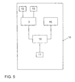
- FIG. 5 schematically illustrated a vehicle with an ignition lock according to the invention, which comprises an automatic transmission.
- Fig. 1 left is an inventive ignition lock 3 in cross section with an inserted key 1 shown.
- a microswitch 2 or button is actuated, whereby the ignition switch 3 from a rest state to a first operating state in which the S-contact of the ignition switch 3 is actuated, so that, for example a radio of a vehicle 10, in which the ignition lock is installed, is supplied with energy.
- the microswitch 2 is no longer actuated, whereby the ignition lock 3 returns to the idle state.
- FIG. 1 On the right side of the Fig. 1 is in perspective the ignition lock 3 shown from the front. It can be seen a rotor 4 of the ignition, which can be rotated in one of the two directions of rotation 11 shown when the key 1 is inserted into a key holder 6 of the ignition switch 3 and rotated to the appropriate side.
- Fig. 2 are the two rotational positions P2l, P2r shown, via which an ignition of the vehicle can be activated or deactivated or an engine of the vehicle can be started or stopped.
- Reference numeral 5 denotes an angle by which the key 1 or, more specifically, the rotor 4 must be turned to the right or to the left to activate or deactivate the ignition or to start or stop the engine.
- Whether the corresponding rotational position P2l, P2r has been achieved or whether the rotor 4 has been rotated by the corresponding angle 5 to the right or to the left can be detected, for example, via a microswitch, which is actuated when the rotor 4 by the predetermined angle 5 is turned to the right or to the left.
- the respective output rotational position is in both in Fig. 2 shown cases represented by the reference P1.
- the rotational position P1 assumes the rotor 4 and thus the key 1 in each case when no manual force is applied by the driver on the key 1 and thus the rotor 4. In other words, the rotor 4 returns to the rotational position P1 as soon as the key 1 is released.
- the reference character P1 is also intended to express that the key 1 can only be rotated when it is in the position P1, ie when the key 1 is inserted into the key holder 6 up to the position P1.
- Fig. 3 the transition of different key positions is shown. It can be seen that the key 1, starting from the position P0, can only be brought to the position P2 via the position P1. This means that the key can only assume the rotational position P2 (better P2l or P2r) if it has previously been inserted into the key holder 6 up to the position P1. While the transition from P0 to P1, from P1 to P0 and from P1 to P2 is done manually by a corresponding actuation of the key by the driver, the transition from P2 to P1 is automatic, since the key 1, for example by spring force from each rotational position in the rotational position P1 is turned back.
- Fig. 4 schematically represents an inventive vehicle 10 with an ignition lock or electronic ignition lock (EZS) 3 according to the invention.
- the vehicle 10 includes a motor 12, an ignition 13, a controller 18, a transmission 16 with a clutch 14 and a brake 17th
- the ignition switch 3 sends a signal to turn the key Engine 12 to start.
- Fig. 5 schematically represents an inventive vehicle 10 with an ignition lock 3 according to the invention.
- This in Fig. 5 illustrated vehicle 10 is the in Fig. 4 shown vehicle very similar, with the only difference that instead of the gearbox 16, the in Fig. 5 illustrated vehicle comprises an automatic transmission 15. Therefore, the controller 18 checks in the vehicle 10 of Fig. 5 whether the automatic transmission 15 is in the parking position and whether the brake 17 is actuated, and this signals the ignition lock 3. If these two conditions are met while the key 1 in the event that the engine 12 is not running, in the position P2r or P2l is turned to the right or to the left, the ignition switch 3 sends out the signal to start the engine 12.
- the engine 12 and / or the ignition 13 can thus be started by turning the key 1 both to the right and to the left without the clutch pedal having to be depressed in a manual transmission or the brake pedal having to be depressed in an automatic transmission, ie starting the engine or the ignition is possible without pedal operation.
Landscapes
- Engineering & Computer Science (AREA)
- Mechanical Engineering (AREA)
- Lock And Its Accessories (AREA)
Abstract
Description
- Die vorliegende Erfindung betrifft ein Verfahren zum Betreiben eines Fahrzeugs und ein entsprechendes Zündschloss für dieses Fahrzeug, welches gleichermaßen für rechtsgesteuerte und linksgesteuerte Fahrzeuge einsetzbar ist.
- Nach dem Stand der Technik sind so genannte Drückkonzepte bekannt, wobei ein Fahrer einen Motor seines Fahrzeugs durch einen Drückvorgang startet. Dieses Drückkonzept ist für die meisten Fahrer ungewohnt und führt deshalb zu Fehlbedienungen. Darüber hinaus sind nach dem Stand der Technik so genannte Drehkonzepte bekannt, wobei der Motor über einen Drehvorgang, welcher über mehrere Raststellungen erfolgt, gestartet wird. Auch dieses Drehkonzept wird von den meisten Fahrern als umständlich angesehen.
- Daher ist es die Aufgabe der vorliegenden Erfindung die nach dem Stand der Technik bekannten Nachteile zu überwinden.
- Erfindungsgemäß wird diese Aufgabe durch ein Verfahren zum Betreiben eines Fahrzeugs nach Anspruch 1, ein Zündschloss für ein Fahrzeug nach Anspruch 9 und ein Fahrzeug nach Anspruch 11 erfüllt. Die abhängigen Ansprüche definieren bevorzugte und vorteilhafte Ausführungsformen der vorliegenden Erfindung.
- Im Rahmen der vorliegenden Erfindung wird ein Verfahren zum Betreiben eines Fahrzeugs bereitgestellt. Dabei wird innerhalb des Fahrzeugs ein Bedienteil, insbesondere ein Zündschlüssel, des Fahrzeugs manuell gedreht, um einen Motor des Fahrzeugs zu starten. Dabei wird der Motor sowohl gestartet, wenn das Bedienteil nach rechts gedreht wird, als auch gestartet, wenn das Bedienteil nach links gedreht wird. Mit anderen Worten wird der Motor des Fahrzeugs sowohl durch eine Drehbewegung des Bedienteils nach rechts als auch durch eine Drehbewegung des Bedienteils nach links gestartet.
- Eine Drehbewegung des Bedienteils nach rechts bzw. links liegt dabei genauer gesagt dann vor, wenn das Bedienteil um mehr als einen vorbestimmten Winkel nach rechts bzw. links gedreht wird. Dieser Drehvorgang des Bedienteils kann dabei von einem Taster erfasst werden, welcher betätigt wird, wenn das Bedienteil um mehr als den vorbestimmten Winkel nach rechts bzw. links gedreht wird.
- Indem der Motor sowohl durch eine Drehung nach links als auch durch eine Drehung nach rechts gestartet werden kann, ist das Verfahren zum Betreiben des Fahrzeugs sowohl für rechts gesteuerte Fahrzeuge als auch für links gesteuerte Fahrzeuge gleichermaßen einsetzbar. Dadurch kann beispielsweise ein Zündschloss, welches entsprechend dem erfindungsgemäßen Verfahren arbeitet, sowohl bei rechts gesteuerten als auch bei links gesteuerten Fahrzeugen eingesetzt werden, ohne dass das Zündschloss vorher auf den rechts gesteuerten oder links gesteuerten Fahrzeugtyp angepasst werden muss. Anders ausgedrückt ist das Bedienkonzept für rechtsgesteuerte Fahrzeuge und linksgesteuerte Fahrzeuge identisch.
- Ein Ausschalten des laufenden Motors erfolgt vorteilhafterweise, indem das Bedienteil nach rechts oder nach links gedreht wird.
- Dabei kann das Bedienteil insbesondere nicht abgezogen werden, wenn der Motor läuft. Mit anderen Worten muss der Motor vorher durch eine Drehbewegung des Bedienteils nach rechts oder nach links ausgeschaltet werden, bevor das Bedienteil abgezogen werden kann.
- Das Bedienteil ist dabei insbesondere nur dann drehbar, wenn das Bedienteil vorher bis zu einer vorbestimmten Position eingeschoben worden ist, wobei durch das Einschieben des Bedienteils bis zu dieser vorbestimmten Position ein dieser vorbestimmten Position entsprechender Betriebszustand des Fahrzeugs, beispielsweise ein Schließen des S-Kontakts, angenommen wird. Mit anderen Worten kann der Motor nur gestartet werden, wenn das Bedienteil vorher bis zu der vorbestimmten Position eingeschoben worden ist.
- Dabei wird der Motor insbesondere nur dann gestartet, wenn beim Drehen des Bedienteils bei einem Automatikgetriebe gleichzeitig eine Bremse des Fahrzeugs gedrückt wird und eine Parkstellung eingestellt ist oder bei einem Schaltgetriebe des Fahrzeugs eine Kupplung des Fahrzeugs durchgetreten ist. Dadurch wird beispielsweise vermieden, dass der Motor im eingekuppelten Zustand, d.h. bei nicht-betätigtem Kupplungspedal, gestartet wird.
- Auch die Zündung des Fahrzeugs kann sowohl durch die Drehbewegung des Bedienteils nach rechts als auch durch die Drehbewegung des Bedienteils nach links aktiviert werden, insbesondere bei nicht-betätigter Kupplung bei einem Schaltgetriebe bzw. bei nicht-betätigter Bremse bei einem Automatikgetriebe.
- Eine Deaktivierung der aktivierten Zündung erfolgt ebenfalls durch die Drehbewegung des Bedienteils nach rechts oder links.
- Bei eingeschalteter Zündung kann das Bedienteil nicht abgezogen werden, was bedeutet, dass zuerst die Zündung mit der entsprechenden Drehbewegung nach rechts oder links deaktiviert werden muss, bevor das Bedienteil abgezogen werden kann.
- Nach einem manuellen Drehvorgang des Bedienteils kehrt das Bedienteil insbesondere automatisch in eine Ausgangslage zurück, d.h. das Bedienteil wird beispielsweise durch Federkraft aus jeder beliebigen Drehposition automatisch in diese Ausgangslage zurück gedreht. Dadurch entfällt die Notwendigkeit das Design und die Anmutung an unterschiedliche Drehpositionen des Bedienteils anzupassen. Das Design kann dadurch an eine einzige Drehposition, in welcher sich das Bedienteil vor und nach der Betätigung befindet, angepasst werden. Darüber hinaus bietet dieses Merkmal den Vorteil, dass das Bedienteil nicht manuell zurück gedreht werden muss.
- Im Rahmen der vorliegenden Erfindung wird auch ein Zündschloss für ein Fahrzeug bereitgestellt. Dieses Zündschloss umfasst eine Bedienteilaufnahme, um ein Bedienteil, insbesondere einen Zündschlüssel, aufzunehmen und einen Rotor. Das Zündschloss ist derart ausgestaltet, dass das Zündschloss ein Signal zum Starten eines Motors des Fahrzeugs ausgibt, wenn der Rotor mittels des Bedienteils (um einen vorbestimmten Winkel) nach rechts gedreht wird, und dass das Zündschloss das Signal zum Starten des Motors auch ausgibt, wenn der Rotor mittels des Bedienteils (um den vorbestimmten Winkel) nach links gedreht wird.
- Die Vorteile des erfindungsgemäßen Zündschlosses entsprechen im Wesentlichen den Vorteilen des erfindungsgemäßen Verfahrens, welche vorab im Detail diskutiert wurden, weshalb hier auf eine Wiederholung verzichtet wird.
- Schließlich wird im Rahmen der vorliegenden Erfindung ein Fahrzeug mit einem erfindungsgemäßen Zündschloss bereitgestellt.
- Die vorliegende Erfindung ist insbesondere für Fahrzeuge geeignet, welche mit einem Zündschlüssel gestartet werden. Selbstverständlich ist die vorliegende Erfindung nicht auf diesen bevorzugten Anwendungsbereich beschränkt, sondern ist prinzipiell auch für Fahrzeuge geeignet, welche beispielsweise über ein Keyless-Entry-System verfügen und bei welchen der Motor über einen erfindungsgemäßen Drehvorgang eines fest im Fahrzeug installierten Bedienteils gestartet wird. Darüber hinaus ist die vorliegende Erfindung auch bei Flugzeugen, Schiffen und gleisgebundenen Fahrzeugen einsetzbar.
- Im Folgenden wird die Erfindung anhand bevorzugter Ausführungsformen mit Bezug auf die Figuren im Detail erläutert.
- In
Fig. 1 ist ein erfindungsgemäßes Zündschloss zum einen im Querschnitt mit einem eingeschobenen Schlüssel und zum anderen perspektivisch von vorn dargestellt. - In
Fig. 2 ist links eine linke Drehposition des Schlüssels und rechts eine rechte Drehposition des Schlüssels zum Startern eines Motors dargestellt. -
Fig. 3 stellt schematisch einen Übergang zwischen verschiedenen Schlüsselpositionen dar. - In
Fig. 4 ist schematisch ein Fahrzeug mit einem erfindungsgemäßen Zündschloss dargestellt, welches ein Schaltgetriebe umfasst. - Dagegen ist in
Fig. 5 schematisch ein Fahrzeug mit einem erfindungsgemäßen Zündschloss dargestellt, welches ein Automatikgetriebe umfasst. - In
Fig. 1 ist links ein erfindungsgemäßes Zündschloss 3 im Querschnitt mit einem eingeschobenen Schlüssel 1 dargestellt. Wenn der Schlüssel zu einer Position P1 in das Zündschloss 3 eingeschoben ist, wird ein Mikroschalter 2 oder Taster betätigt, wodurch das Zündschloss 3 aus einem Ruhezustand in einen ersten Betriebszustand übergeht, in welchem der S-Kontakt des Zündschlosses 3 betätigt ist, so dass beispielsweise ein Radio eines Fahrzeugs 10, in welchem das Zündschloss eingebaut ist, mit Energie versorgt wird. Sobald der Schlüssel 1 wieder aus dem Zündschloss 3 herausgezogen wird und zu Position P0 gelangt, wird der Mikroschalter 2 nicht mehr betätigt, wodurch das Zündschloss 3 wieder in den Ruhezustand übergeht. - Auf der rechten Seite der
Fig. 1 ist perspektivisch das Zündschloss 3 von vorn dargestellt. Man erkennt einen Rotor 4 des Zündschlosses, welcher in eine der beiden dargestellten Drehrichtungen 11 gedreht werden kann, wenn der Schlüssel 1 in eine Schlüsselaufnahme 6 des Zündschlosses 3 eingeführt und zu der entsprechenden Seite gedreht wird. - In
Fig. 2 sind die beiden Drehpositionen P2l, P2r dargestellt, über welche eine Zündung des Fahrzeugs aktiviert oder deaktiviert oder ein Motor des Fahrzeugs gestartet oder gestoppt werden kann. Mit Bezugszeichen 5 ist ein Winkel bezeichnet, um welchen der Schlüssel 1 oder genauer der Rotor 4 nach rechts oder nach links gedreht werden muss, um die Zündung zu aktivieren oder zu deaktivieren oder den Motor zu starten oder zu stoppen. Ob die entsprechende Drehposition P2l, P2r erreicht worden ist bzw. ob der Rotor 4 um den entsprechenden Winkel 5 nach rechts oder nach links gedreht worden ist, kann beispielsweise über einen Mikroschalter erfasst werden, welcher betätigt wird, wenn der Rotor 4 um den vorbestimmten Winkel 5 nach rechts oder nach links gedreht wird. Die jeweilige Ausgangsdrehposition ist in beiden inFig. 2 dargestellten Fällen mit dem Bezugszeichen P1 dargestellt. Die Drehposition P1 nimmt der Rotor 4 und damit der Schlüssel 1 jeweils an, wenn keine manuelle Kraft von dem Fahrer auf den Schlüssel 1 und damit den Rotor 4 aufgebracht wird. Anders ausgedrückt dreht sich der Rotor 4 in die Drehposition P1 zurück, sobald der Schlüssel 1 losgelassen wird. Mit dem Bezugszeichen P1 soll auch zum Ausdruck gebracht werden, dass der Schlüssel 1 nur dann gedreht werden kann, wenn er sich in der Position P1 befindet, d.h. wenn der Schlüssel 1 bis zu der Position P1 in die Schlüsselaufnahme 6 eingeschoben ist. - In
Fig. 3 ist der Übergang verschiedener Schlüsselpositionen dargestellt. Man erkennt dass der Schlüssel 1 ausgehend von der Position P0 nur über die Position P1 in die Position P2 gebracht werden kann. Das bedeutet, dass der Schlüssel nur dann die Drehposition P2 (besser P2l oder P2r) einnehmen kann, wenn er vorher bis zu der Position P1 in die Schlüsselaufnahme 6 eingeschoben worden ist. Während der Übergang von P0 nach P1, von P1 nach P0 und von P1 nach P2 jeweils manuell durch eine entsprechende Betätigung des Schlüssels durch den Fahrer erfolgt, erfolgt der Übergang von P2 nach P1 automatisch, da der Schlüssel 1 beispielsweise mittels Federkraft aus jeder Drehposition in die Drehposition P1 zurückgedreht wird. - Im Folgenden werden bestimmte Bedienvorgänge des erfindungsgemäßen Zündschlosses 3 beschrieben.
- 1. Der Schlüssel 1 wird in die Schlüsselaufnahme 6 des Zündschlosses 3 gesteckt und bis in die Position P1 eingeführt, wo er einrastet und der S-Kontakt geschlossen wird. Dadurch kann beispielsweise ein Radio des Fahrzeugs 10 betrieben werden.
- 2. Indem der Schlüssel 1 aus der Position P1 in die Position P2r oder P21 nach rechts oder nach links gedreht wird, wird die Zündung aktiviert, wenn sie vorher nicht aktiviert war. Nach diesem Drehvorgang kehrt der Schlüssel 1 in die Ausgangslage P1 zurück und wird in dieser Position P1 gehalten, was bedeutet, dass der Schlüssel 1 nicht aus der Schlüsselaufnahme 6 herausgezogen werden kann, solange die Zündung aktiviert ist. Die Zündung wird übrigens nur dann aktiviert, wenn die zum Start des Motors notwendigen Zusatzbedingungen (siehe Punkt 3 unten) nicht erfüllt sind.
- 3. Indem der Schlüssel in die Position P2r oder P2l nach rechts oder nach links gedreht wird, wird der Motor gestartet, wenn
bei einem Schaltgetriebe die Kupplung gedrückt gehalten wird, oder
bei einem Automatikgetriebe die Parkstellung eingestellt ist und die Bremse betätigt wird.
Diese Bedingungen bezüglich des Schaltgetriebes oder des Automatikgetriebes sind die Zusatzbedingungen, welche bereits bei Punkt 2 erwähnt sind. Nach diesem Drehvorgang zum Starten des Motors kehrt der Schlüssel 1 in die Ausgangslage P1 zurück und wird in dieser Position P1 gehalten, was bedeutet, dass der Schlüssel 1 nicht aus der Schlüsselaufnahme 6 herausgezogen werden kann, solange der Motor läuft.
Der Motor wird übrigens auch dann gestartet, wenn die Zündung vorher nicht aktiviert worden ist. - 4. Um die aktive Zündung auszuschalten, wird der Schlüssel 1 in die Position P2r oder P2l nach rechts oder nach links gedreht. Die Zündung wird übrigens nur dann ausgeschaltet, wenn die zum Start des Motors notwendigen Zusatzbedingungen (siehe Punkt 3 oben) nicht erfüllt sind, da sonst der Motor gestartet wird (siehe Punkt 3 oben). Nach diesem Drehvorgang kehrt der Schlüssel 1 in die Ausgangslage P1 zurück und wird zum Abziehen freigegeben, was bedeutet, dass er aus der Schlüsselaufnahme 6 entfernt werden kann.
- 5. Um den laufenden Motor auszuschalten, wird der Schlüssel 1 in die Position P2r oder P21 nach rechts oder nach links gedreht. Nach diesem Drehvorgang kehrt der Schlüssel 1 in die Ausgangslage P1 zurück und wird zum Abziehen freigegeben, was bedeutet, dass er aus der Schlüsselaufnahme 6 entfernt werden kann.
- 6. Wenn der Schlüssel 1 zum Abziehen freigegeben ist und aus der Schlüsselaufnahme 6 und damit aus dem Zündschloss 3 herausgezogen wird, wird der S-Kontakt nicht mehr betätigt, wodurch beispielsweise das Radio stromlos wird.
-
Fig. 4 stellt schematisch ein erfindungsgemäßes Fahrzeug 10 mit einem erfindungsgemäßen Zündschloss oder elektronischem Zündanlassschloss (EZS) 3 dar. Neben dem Zündschloss 3 umfasst das Fahrzeug 10 einen Motor 12, eine Zündung 13, eine Steuerung 18, ein Schaltgetriebe 16 mit einer Kupplung 14 und eine Bremse 17. Wenn beispielsweise bei dem nicht laufenden Motor 12 der Schlüssel 1 in die Position P2r oder P21 nach rechts oder nach links gedreht wird und wenn die Steuerung 18 erfasst, dass die Kupplung 14 getreten betätigt wird, sendet das Zündschloss 3 ein Signal aus, um den Motor 12 zu starten. -
Fig. 5 stellt schematisch ein erfindungsgemäßes Fahrzeug 10 mit einem erfindungsgemäßen Zündschloss 3 dar. Dieses inFig. 5 dargestellte Fahrzeug 10 ist dem inFig. 4 dargestellten Fahrzeug sehr ähnlich, mit dem einzigen Unterschied, dass anstelle des Schaltgetriebes 16 das inFig. 5 dargestellte Fahrzeug ein Automatikgetriebe 15 umfasst. Daher überprüft die Steuerung 18 bei dem Fahrzeug 10 derFig. 5 , ob sich das Automatikgetriebe 15 in der Parkstellung befindet und ob die Bremse 17 betätigt wird, und meldet dies dem Zündschloss 3. Wenn diese beiden Bedingungen erfüllt sind und gleichzeitig der Schlüssel 1 für den Fall, dass der Motor 12 nicht läuft, in die Position P2r oder P2l nach rechts oder nach links gedreht wird, sendet das Zündschloss 3 das Signal aus, um den Motor 12 zu starten. - Erfindungsgemäß kann somit der Motor 12 und/oder die Zündung 13 durch Drehen des Schlüssels 1 sowohl nach rechts als auch nach links gestartet werden, ohne dass bei einem Schaltgetriebe das Kupplungspedal bzw. bei einem Automatikgetriebe das Bremspedal niedergedrückt sein muss, d.h. das Starten des Motors bzw. der Zündung ist ohne Pedalbetätigung möglich.
-
- 1
- Schlüssel
- 2
- Mikroschalter
- 3
- Zündschloss
- 4
- Rotor
- 5
- Winkel
- 6
- Schlüsselaufnahme
- 10
- Fahrzeug
- 11
- Drehrichtung
- 12
- Motor
- 13
- Zündung
- 14
- Kupplung
- 15
- Automatikgetriebe
- 16
- Schaltgetriebe
- 17
- Bremse
- 18
- Steuerung
- P0
- Position
- P1
- Position
- P2r
- Position
- P21
- Position
Claims (11)
- Verfahren zum Betreiben eines Fahrzeugs,
wobei ein Bedienteil (1) des Fahrzeugs (10) innerhalb des Fahrzeugs (10) manuell gedreht wird, um einen Motor (12) des Fahrzeugs (10) zu starten und/oder eine Zündung (13) des Fahrzeugs (10) zu aktivieren,
dadurch gekennzeichnet,
dass der Motor (12) und/oder die Zündung (13) sowohl durch Drehen des Bedienteils (1) nach rechts als auch durch Drehen des Bedienteils (1) nach links gestartet werden kann. - Verfahren nach Anspruch 1, dadurch gekennzeichnet, dass der laufende Motor (12) ausgeschaltet wird, indem das Bedienteil (1) nach rechts oder nach links gedreht wird.
- Verfahren nach Anspruch 1 oder 2, dadurch gekennzeichnet, dass das Bedienteil (1) nicht abziehbar ist, wenn der Motor (12) läuft.
- Verfahren nach einem der vorhergehenden Ansprüche, dadurch gekennzeichnet, dass eine eingeschaltete Zündung (13) des Fahrzeugs (10) ausgeschaltet wird, indem das Bedienteil (1) nach rechts oder nach links gedreht wird.
- Verfahren nach Anspruch 4, dadurch gekennzeichnet, dass das Bedienteil (1) nicht abziehbar ist, wenn die Zündung (13) eingeschaltet ist.
- Verfahren nach einem der vorhergehenden Ansprüche, dadurch gekennzeichnet, dass das Bedienteil (1) automatisch in eine Ausgangslage (P1) zurück gedreht wird, nachdem das Bedienteil (1) manuell gedreht wurde.
- Verfahren nach einem der vorhergehenden Ansprüche, dadurch gekennzeichnet, dass das Bedienteil (1) nur dann drehbar ist, wenn das Bedienteil (1) in eine vorbestimmte Position (P1) eingeschoben ist, und dass durch das Einschieben bis zu der vorbestimmten Position (P1) ein der vorbestimmten Position (P1) entsprechender Betriebszustand des Fahrzeuges (10) erreicht wird.
- Verfahren nach einem der vorhergehenden Ansprüche, dadurch gekennzeichnet, dass der Motor (12) nur dann gestartet wird, wenn beim Drehen des Bedienteils (1) bei einem Automatikgetriebe (15) des Fahrzeugs (10) eine Bremse (17) des Fahrzeugs (10) gedrückt wird und eine Parkstellung eingestellt ist oder wenn beim Drehen des Bedienteils (1) bei einem Schaltgetriebe (16) des Fahrzeugs (10) eine Kupplung (14) des Fahrzeugs (10) getreten ist.
- Zündschloss für ein Fahrzeug,
welches eine Bedienteilaufnahme (6) zur Aufnahme eines Bedienteils (1) und einen Rotor (4) umfasst,
dadurch gekennzeichnet,
dass das Zündschloss (3) derart ausgestaltet ist,• dass das Zündschloss (1) ein Signal zum Starten eines Motors (12) des Fahrzeugs (10) und/oder zum Aktivieren einer Zündung (13) des Fahrzeugs (10) ausgibt, wenn der Rotor (4) mittels des Bedienteils (1) nach rechts gedreht wird, und• dass das Zündschloss (3) das Signal zum Starten des Motors (12) und/oder zum Aktivieren der Zündung (13) auch ausgibt, wenn der Rotor (4) mittels des Bedienteils (1) nach links gedreht wird. - Zündschloss nach Anspruch 9, dadurch gekennzeichnet, dass das Zündschloss (3) zur Durchführung des Verfahrens nach einem der Ansprüche 1-8 ausgestaltet ist.
- Fahrzeug mit einem Zündschloss nach Anspruch 9 oder 10
Applications Claiming Priority (1)
| Application Number | Priority Date | Filing Date | Title |
|---|---|---|---|
| DE102008035126A DE102008035126A1 (de) | 2008-07-28 | 2008-07-28 | Verfahren zum Betreiben eines Fahrzeugs und entsprechendes Zündschloss |
Publications (2)
| Publication Number | Publication Date |
|---|---|
| EP2149483A1 true EP2149483A1 (de) | 2010-02-03 |
| EP2149483B1 EP2149483B1 (de) | 2014-03-26 |
Family
ID=41226394
Family Applications (1)
| Application Number | Title | Priority Date | Filing Date |
|---|---|---|---|
| EP09009280.0A Active EP2149483B1 (de) | 2008-07-28 | 2009-07-16 | Verfahren zum Betreiben eines Fahrzeugs und entsprechendes Zündschloss |
Country Status (2)
| Country | Link |
|---|---|
| EP (1) | EP2149483B1 (de) |
| DE (1) | DE102008035126A1 (de) |
Citations (1)
| Publication number | Priority date | Publication date | Assignee | Title |
|---|---|---|---|---|
| US3609260A (en) | 1968-07-15 | 1971-09-28 | Brevets Neiman Sa Soc D Expl D | Cylindrical switch for ignition and starting of engines and other uses |
Family Cites Families (8)
| Publication number | Priority date | Publication date | Assignee | Title |
|---|---|---|---|---|
| DE19907374B4 (de) * | 1999-02-20 | 2016-08-18 | Volkswagen Ag | Elektronisches Zündstartschloßsystem für ein Kraftfahrzeug |
| DE19938888C2 (de) * | 1999-08-17 | 2002-01-17 | Siemens Ag | Zündanlaßschalter |
| DE19951987C1 (de) * | 1999-10-28 | 2001-06-28 | Huf Huelsbeck & Fuerst Gmbh | Schlüsselbetätigbarer Zündanlassschalter für Kraftfahrzeuge |
| JP4137657B2 (ja) * | 2003-02-06 | 2008-08-20 | 株式会社東海理化電機製作所 | エンジン始動・停止用スイッチ装置 |
| DE102004037439A1 (de) * | 2004-07-30 | 2006-03-23 | Siemens Ag | Zündanlassschalter für Fahrzeuge |
| DE102005037440A1 (de) * | 2004-08-11 | 2006-02-23 | Marquardt Gmbh | Zündschloß für ein Kraftfahrzeug |
| EP1816040B1 (de) * | 2006-02-01 | 2008-09-10 | Ford Global Technologies, LLC | Fahrzeugschlüsselsystem |
| DE102006014377A1 (de) * | 2006-03-27 | 2007-10-11 | Siemens Ag | Zündschloss und Kraftfahrzeug |
-
2008
- 2008-07-28 DE DE102008035126A patent/DE102008035126A1/de not_active Withdrawn
-
2009
- 2009-07-16 EP EP09009280.0A patent/EP2149483B1/de active Active
Patent Citations (1)
| Publication number | Priority date | Publication date | Assignee | Title |
|---|---|---|---|---|
| US3609260A (en) | 1968-07-15 | 1971-09-28 | Brevets Neiman Sa Soc D Expl D | Cylindrical switch for ignition and starting of engines and other uses |
Also Published As
| Publication number | Publication date |
|---|---|
| EP2149483B1 (de) | 2014-03-26 |
| DE102008035126A1 (de) | 2010-02-04 |
Similar Documents
| Publication | Publication Date | Title |
|---|---|---|
| EP2855216B1 (de) | Feststellbremsensystem für ein fahrzeug | |
| EP2001717B1 (de) | Elektrische Parkbremse mit einem Bedienelement zur Umschaltung in einen Servicemodus | |
| EP0972667B1 (de) | Kraftfahrzeug mit einem elektronisch gesteuerten Automatikgetriebe und einer fremdkraftbetätigten Feststellbremse | |
| EP3036142B1 (de) | Verfahren zum bedienen eines fahrerassistenzsystems eines kraftfahrzeugs mit wenigstens einer bedienvorrichtung | |
| DE102010003232A1 (de) | Verfahren zum Betreiben einer Bremsanlage, Bremsanlage und Kraftfahrzeug | |
| EP3740406B1 (de) | Assistenzsystem für ein fahrzeug | |
| DE102010055921A1 (de) | Verfahren zum automatischen Aktivieren einer Parkfunktionalität eines automatischen oder automatisierten Getriebes in einem Fahrzeug | |
| DE102008048179A1 (de) | Kraftfahrzeug mit Antriebsmotor, Bremseinrichtung und Steuergerät | |
| EP2167846A1 (de) | Verfharen zur ansteuerung einer fahrstufe in einem automatischen oder automatisierten getriebe eines kraftfahrzeugs und entsprechendes kraftfahrzeug | |
| DE102010007899B4 (de) | Kraftfahrzeug mit einem Längsführungssystem mit STOP- & GO-Funktion und einer automatisch einlegbaren Parkbremse | |
| DE10315023A1 (de) | Verfahren zum Betreiben eines Fortbewegungsmittels und entsprechende Vorrichtung | |
| EP2559600B1 (de) | Verfahren zum Verzögern eines Fahrzeugs | |
| EP2149483B1 (de) | Verfahren zum Betreiben eines Fahrzeugs und entsprechendes Zündschloss | |
| DE102013015727A1 (de) | Fahrerassistenzvorrichtung | |
| DE10253936A1 (de) | Verfahren zur Sicherung eines KFZ gegen Wegrollen nach Abstellen des Motors sowie Sicherheitseinrichtung | |
| DE102008042490A1 (de) | Verfahren und Vorrichtung zur Aktivierung der Feststellbremse | |
| EP2560853A1 (de) | Hybridfahrzeug mit wegfahrsperre | |
| EP1192067B1 (de) | Vorrichtung sowie verfahren für die fahrsituationsabhängige betätigung einer bremsanlage eines kraftfahrzeuges | |
| DE102006058854B4 (de) | Verfahren zur Betätigung von zu öffnenden Einrichtungen eines Kraftfahrzeugs sowie entsprechende Vorrichtung und entsprechendes Kraftfahrzeug | |
| EP0995650A2 (de) | Vorrichtung und Verfahren zum Starten eines Kraftfahrzeugs | |
| DE102015012550A1 (de) | Verfahren zum Steuern eines Kraftfahrzeugs | |
| DE102006049419A1 (de) | Kraftfahrzeug mit einem Fahrberechtigungssystem und einem elektronisch steuerbaren Parkbremssystem sowie Verfahren zu dessen Betrieb | |
| DE102010018329A1 (de) | Elektrisch betätigbare Handbremse für ein Fahrzeug | |
| DE10351589A1 (de) | Betätigungsvorrichtung für eine elektromechanische Parkbremse | |
| DE102004029858B4 (de) | Lenksystem mit einer Lenkverriegelungsvorrichtung und einem Servolenksystem sowie Verfahren zur Ansteuerung eines solchen Servolenksystems |
Legal Events
| Date | Code | Title | Description |
|---|---|---|---|
| PUAI | Public reference made under article 153(3) epc to a published international application that has entered the european phase |
Free format text: ORIGINAL CODE: 0009012 |
|
| AK | Designated contracting states |
Kind code of ref document: A1 Designated state(s): AT BE BG CH CY CZ DE DK EE ES FI FR GB GR HR HU IE IS IT LI LT LU LV MC MK MT NL NO PL PT RO SE SI SK SM TR |
|
| AX | Request for extension of the european patent |
Extension state: AL BA RS |
|
| 17P | Request for examination filed |
Effective date: 20100803 |
|
| 17Q | First examination report despatched |
Effective date: 20100913 |
|
| RAP1 | Party data changed (applicant data changed or rights of an application transferred) |
Owner name: VOLKSWAGEN AKTIENGESELLSCHAFT |
|
| RIC1 | Information provided on ipc code assigned before grant |
Ipc: B60R 25/20 20130101ALI20130613BHEP Ipc: B60R 25/04 20130101AFI20130613BHEP |
|
| GRAP | Despatch of communication of intention to grant a patent |
Free format text: ORIGINAL CODE: EPIDOSNIGR1 |
|
| INTG | Intention to grant announced |
Effective date: 20131018 |
|
| GRAS | Grant fee paid |
Free format text: ORIGINAL CODE: EPIDOSNIGR3 |
|
| GRAA | (expected) grant |
Free format text: ORIGINAL CODE: 0009210 |
|
| AK | Designated contracting states |
Kind code of ref document: B1 Designated state(s): AT BE BG CH CY CZ DE DK EE ES FI FR GB GR HR HU IE IS IT LI LT LU LV MC MK MT NL NO PL PT RO SE SI SK SM TR |
|
| REG | Reference to a national code |
Ref country code: GB Ref legal event code: FG4D Free format text: NOT ENGLISH |
|
| REG | Reference to a national code |
Ref country code: CH Ref legal event code: EP |
|
| REG | Reference to a national code |
Ref country code: AT Ref legal event code: REF Ref document number: 658802 Country of ref document: AT Kind code of ref document: T Effective date: 20140415 |
|
| REG | Reference to a national code |
Ref country code: IE Ref legal event code: FG4D Free format text: LANGUAGE OF EP DOCUMENT: GERMAN |
|
| REG | Reference to a national code |
Ref country code: DE Ref legal event code: R096 Ref document number: 502009009053 Country of ref document: DE Effective date: 20140508 |
|
| REG | Reference to a national code |
Ref country code: DE Ref legal event code: R081 Ref document number: 502009009053 Country of ref document: DE Owner name: MARQUARDT GMBH, DE Free format text: FORMER OWNER: VOLKSWAGEN AKTIENGESELLSCHAFT, 38440 WOLFSBURG, DE Effective date: 20140409 Ref country code: DE Ref legal event code: R081 Ref document number: 502009009053 Country of ref document: DE Owner name: VOLKSWAGEN AKTIENGESELLSCHAFT, DE Free format text: FORMER OWNER: VOLKSWAGEN AKTIENGESELLSCHAFT, 38440 WOLFSBURG, DE Effective date: 20140409 |
|
| PG25 | Lapsed in a contracting state [announced via postgrant information from national office to epo] |
Ref country code: NO Free format text: LAPSE BECAUSE OF FAILURE TO SUBMIT A TRANSLATION OF THE DESCRIPTION OR TO PAY THE FEE WITHIN THE PRESCRIBED TIME-LIMIT Effective date: 20140626 Ref country code: LT Free format text: LAPSE BECAUSE OF FAILURE TO SUBMIT A TRANSLATION OF THE DESCRIPTION OR TO PAY THE FEE WITHIN THE PRESCRIBED TIME-LIMIT Effective date: 20140326 |
|
| REG | Reference to a national code |
Ref country code: NL Ref legal event code: VDEP Effective date: 20140326 |
|
| REG | Reference to a national code |
Ref country code: LT Ref legal event code: MG4D |
|
| PG25 | Lapsed in a contracting state [announced via postgrant information from national office to epo] |
Ref country code: FI Free format text: LAPSE BECAUSE OF FAILURE TO SUBMIT A TRANSLATION OF THE DESCRIPTION OR TO PAY THE FEE WITHIN THE PRESCRIBED TIME-LIMIT Effective date: 20140326 Ref country code: SE Free format text: LAPSE BECAUSE OF FAILURE TO SUBMIT A TRANSLATION OF THE DESCRIPTION OR TO PAY THE FEE WITHIN THE PRESCRIBED TIME-LIMIT Effective date: 20140326 |
|
| PG25 | Lapsed in a contracting state [announced via postgrant information from national office to epo] |
Ref country code: LV Free format text: LAPSE BECAUSE OF FAILURE TO SUBMIT A TRANSLATION OF THE DESCRIPTION OR TO PAY THE FEE WITHIN THE PRESCRIBED TIME-LIMIT Effective date: 20140326 Ref country code: HR Free format text: LAPSE BECAUSE OF FAILURE TO SUBMIT A TRANSLATION OF THE DESCRIPTION OR TO PAY THE FEE WITHIN THE PRESCRIBED TIME-LIMIT Effective date: 20140326 |
|
| PG25 | Lapsed in a contracting state [announced via postgrant information from national office to epo] |
Ref country code: EE Free format text: LAPSE BECAUSE OF FAILURE TO SUBMIT A TRANSLATION OF THE DESCRIPTION OR TO PAY THE FEE WITHIN THE PRESCRIBED TIME-LIMIT Effective date: 20140326 Ref country code: IS Free format text: LAPSE BECAUSE OF FAILURE TO SUBMIT A TRANSLATION OF THE DESCRIPTION OR TO PAY THE FEE WITHIN THE PRESCRIBED TIME-LIMIT Effective date: 20140726 Ref country code: RO Free format text: LAPSE BECAUSE OF FAILURE TO SUBMIT A TRANSLATION OF THE DESCRIPTION OR TO PAY THE FEE WITHIN THE PRESCRIBED TIME-LIMIT Effective date: 20140326 Ref country code: CZ Free format text: LAPSE BECAUSE OF FAILURE TO SUBMIT A TRANSLATION OF THE DESCRIPTION OR TO PAY THE FEE WITHIN THE PRESCRIBED TIME-LIMIT Effective date: 20140326 Ref country code: CY Free format text: LAPSE BECAUSE OF FAILURE TO SUBMIT A TRANSLATION OF THE DESCRIPTION OR TO PAY THE FEE WITHIN THE PRESCRIBED TIME-LIMIT Effective date: 20140326 Ref country code: NL Free format text: LAPSE BECAUSE OF FAILURE TO SUBMIT A TRANSLATION OF THE DESCRIPTION OR TO PAY THE FEE WITHIN THE PRESCRIBED TIME-LIMIT Effective date: 20140326 Ref country code: BG Free format text: LAPSE BECAUSE OF FAILURE TO SUBMIT A TRANSLATION OF THE DESCRIPTION OR TO PAY THE FEE WITHIN THE PRESCRIBED TIME-LIMIT Effective date: 20140626 |
|
| PG25 | Lapsed in a contracting state [announced via postgrant information from national office to epo] |
Ref country code: SK Free format text: LAPSE BECAUSE OF FAILURE TO SUBMIT A TRANSLATION OF THE DESCRIPTION OR TO PAY THE FEE WITHIN THE PRESCRIBED TIME-LIMIT Effective date: 20140326 Ref country code: ES Free format text: LAPSE BECAUSE OF FAILURE TO SUBMIT A TRANSLATION OF THE DESCRIPTION OR TO PAY THE FEE WITHIN THE PRESCRIBED TIME-LIMIT Effective date: 20140326 Ref country code: PL Free format text: LAPSE BECAUSE OF FAILURE TO SUBMIT A TRANSLATION OF THE DESCRIPTION OR TO PAY THE FEE WITHIN THE PRESCRIBED TIME-LIMIT Effective date: 20140326 |
|
| PG25 | Lapsed in a contracting state [announced via postgrant information from national office to epo] |
Ref country code: PT Free format text: LAPSE BECAUSE OF FAILURE TO SUBMIT A TRANSLATION OF THE DESCRIPTION OR TO PAY THE FEE WITHIN THE PRESCRIBED TIME-LIMIT Effective date: 20140728 |
|
| REG | Reference to a national code |
Ref country code: DE Ref legal event code: R097 Ref document number: 502009009053 Country of ref document: DE |
|
| PG25 | Lapsed in a contracting state [announced via postgrant information from national office to epo] |
Ref country code: DK Free format text: LAPSE BECAUSE OF FAILURE TO SUBMIT A TRANSLATION OF THE DESCRIPTION OR TO PAY THE FEE WITHIN THE PRESCRIBED TIME-LIMIT Effective date: 20140326 |
|
| PLBE | No opposition filed within time limit |
Free format text: ORIGINAL CODE: 0009261 |
|
| STAA | Information on the status of an ep patent application or granted ep patent |
Free format text: STATUS: NO OPPOSITION FILED WITHIN TIME LIMIT |
|
| PG25 | Lapsed in a contracting state [announced via postgrant information from national office to epo] |
Ref country code: LU Free format text: LAPSE BECAUSE OF FAILURE TO SUBMIT A TRANSLATION OF THE DESCRIPTION OR TO PAY THE FEE WITHIN THE PRESCRIBED TIME-LIMIT Effective date: 20140716 |
|
| REG | Reference to a national code |
Ref country code: CH Ref legal event code: PL |
|
| 26N | No opposition filed |
Effective date: 20150106 |
|
| GBPC | Gb: european patent ceased through non-payment of renewal fee |
Effective date: 20140716 |
|
| PG25 | Lapsed in a contracting state [announced via postgrant information from national office to epo] |
Ref country code: IT Free format text: LAPSE BECAUSE OF FAILURE TO SUBMIT A TRANSLATION OF THE DESCRIPTION OR TO PAY THE FEE WITHIN THE PRESCRIBED TIME-LIMIT Effective date: 20140326 |
|
| REG | Reference to a national code |
Ref country code: DE Ref legal event code: R097 Ref document number: 502009009053 Country of ref document: DE Effective date: 20150106 |
|
| REG | Reference to a national code |
Ref country code: IE Ref legal event code: MM4A |
|
| REG | Reference to a national code |
Ref country code: FR Ref legal event code: ST Effective date: 20150331 |
|
| PG25 | Lapsed in a contracting state [announced via postgrant information from national office to epo] |
Ref country code: LI Free format text: LAPSE BECAUSE OF NON-PAYMENT OF DUE FEES Effective date: 20140731 Ref country code: CH Free format text: LAPSE BECAUSE OF NON-PAYMENT OF DUE FEES Effective date: 20140731 |
|
| PG25 | Lapsed in a contracting state [announced via postgrant information from national office to epo] |
Ref country code: GB Free format text: LAPSE BECAUSE OF NON-PAYMENT OF DUE FEES Effective date: 20140716 Ref country code: FR Free format text: LAPSE BECAUSE OF NON-PAYMENT OF DUE FEES Effective date: 20140731 |
|
| PG25 | Lapsed in a contracting state [announced via postgrant information from national office to epo] |
Ref country code: SI Free format text: LAPSE BECAUSE OF FAILURE TO SUBMIT A TRANSLATION OF THE DESCRIPTION OR TO PAY THE FEE WITHIN THE PRESCRIBED TIME-LIMIT Effective date: 20140326 |
|
| PG25 | Lapsed in a contracting state [announced via postgrant information from national office to epo] |
Ref country code: IE Free format text: LAPSE BECAUSE OF NON-PAYMENT OF DUE FEES Effective date: 20140716 |
|
| REG | Reference to a national code |
Ref country code: AT Ref legal event code: MM01 Ref document number: 658802 Country of ref document: AT Kind code of ref document: T Effective date: 20140716 |
|
| PG25 | Lapsed in a contracting state [announced via postgrant information from national office to epo] |
Ref country code: AT Free format text: LAPSE BECAUSE OF NON-PAYMENT OF DUE FEES Effective date: 20140716 |
|
| PG25 | Lapsed in a contracting state [announced via postgrant information from national office to epo] |
Ref country code: SM Free format text: LAPSE BECAUSE OF FAILURE TO SUBMIT A TRANSLATION OF THE DESCRIPTION OR TO PAY THE FEE WITHIN THE PRESCRIBED TIME-LIMIT Effective date: 20140326 Ref country code: MC Free format text: LAPSE BECAUSE OF FAILURE TO SUBMIT A TRANSLATION OF THE DESCRIPTION OR TO PAY THE FEE WITHIN THE PRESCRIBED TIME-LIMIT Effective date: 20140326 |
|
| PG25 | Lapsed in a contracting state [announced via postgrant information from national office to epo] |
Ref country code: MT Free format text: LAPSE BECAUSE OF FAILURE TO SUBMIT A TRANSLATION OF THE DESCRIPTION OR TO PAY THE FEE WITHIN THE PRESCRIBED TIME-LIMIT Effective date: 20140326 Ref country code: GR Free format text: LAPSE BECAUSE OF FAILURE TO SUBMIT A TRANSLATION OF THE DESCRIPTION OR TO PAY THE FEE WITHIN THE PRESCRIBED TIME-LIMIT Effective date: 20140627 |
|
| PG25 | Lapsed in a contracting state [announced via postgrant information from national office to epo] |
Ref country code: BE Free format text: LAPSE BECAUSE OF FAILURE TO SUBMIT A TRANSLATION OF THE DESCRIPTION OR TO PAY THE FEE WITHIN THE PRESCRIBED TIME-LIMIT Effective date: 20140731 Ref country code: TR Free format text: LAPSE BECAUSE OF FAILURE TO SUBMIT A TRANSLATION OF THE DESCRIPTION OR TO PAY THE FEE WITHIN THE PRESCRIBED TIME-LIMIT Effective date: 20140326 Ref country code: HU Free format text: LAPSE BECAUSE OF FAILURE TO SUBMIT A TRANSLATION OF THE DESCRIPTION OR TO PAY THE FEE WITHIN THE PRESCRIBED TIME-LIMIT; INVALID AB INITIO Effective date: 20090716 |
|
| PG25 | Lapsed in a contracting state [announced via postgrant information from national office to epo] |
Ref country code: MK Free format text: LAPSE BECAUSE OF FAILURE TO SUBMIT A TRANSLATION OF THE DESCRIPTION OR TO PAY THE FEE WITHIN THE PRESCRIBED TIME-LIMIT Effective date: 20140326 |
|
| P01 | Opt-out of the competence of the unified patent court (upc) registered |
Effective date: 20230523 |
|
| PGFP | Annual fee paid to national office [announced via postgrant information from national office to epo] |
Ref country code: DE Payment date: 20250731 Year of fee payment: 17 |