EP2149479A1 - Vehicle partition - Google Patents
Vehicle partition Download PDFInfo
- Publication number
- EP2149479A1 EP2149479A1 EP09166291A EP09166291A EP2149479A1 EP 2149479 A1 EP2149479 A1 EP 2149479A1 EP 09166291 A EP09166291 A EP 09166291A EP 09166291 A EP09166291 A EP 09166291A EP 2149479 A1 EP2149479 A1 EP 2149479A1
- Authority
- EP
- European Patent Office
- Prior art keywords
- mounting
- partition
- pin
- vehicle
- trim
- Prior art date
- Legal status (The legal status is an assumption and is not a legal conclusion. Google has not performed a legal analysis and makes no representation as to the accuracy of the status listed.)
- Granted
Links
- 238000005192 partition Methods 0.000 title claims abstract description 69
- 238000003780 insertion Methods 0.000 claims abstract description 4
- 230000037431 insertion Effects 0.000 claims abstract description 4
- 238000000034 method Methods 0.000 claims description 4
- 230000000149 penetrating effect Effects 0.000 claims description 2
- 230000035515 penetration Effects 0.000 claims description 2
- 241000282472 Canis lupus familiaris Species 0.000 description 8
- 241001465754 Metazoa Species 0.000 description 1
- 230000004308 accommodation Effects 0.000 description 1
- 230000004888 barrier function Effects 0.000 description 1
- 230000003203 everyday effect Effects 0.000 description 1
- 230000000717 retained effect Effects 0.000 description 1
- 230000003313 weakening effect Effects 0.000 description 1
Images



Classifications
-
- B—PERFORMING OPERATIONS; TRANSPORTING
- B60—VEHICLES IN GENERAL
- B60R—VEHICLES, VEHICLE FITTINGS, OR VEHICLE PARTS, NOT OTHERWISE PROVIDED FOR
- B60R21/00—Arrangements or fittings on vehicles for protecting or preventing injuries to occupants or pedestrians in case of accidents or other traffic risks
- B60R21/02—Occupant safety arrangements or fittings, e.g. crash pads
- B60R21/026—Rigid partitions inside vehicles, e.g. between passengers and load compartments
-
- F—MECHANICAL ENGINEERING; LIGHTING; HEATING; WEAPONS; BLASTING
- F16—ENGINEERING ELEMENTS AND UNITS; GENERAL MEASURES FOR PRODUCING AND MAINTAINING EFFECTIVE FUNCTIONING OF MACHINES OR INSTALLATIONS; THERMAL INSULATION IN GENERAL
- F16B—DEVICES FOR FASTENING OR SECURING CONSTRUCTIONAL ELEMENTS OR MACHINE PARTS TOGETHER, e.g. NAILS, BOLTS, CIRCLIPS, CLAMPS, CLIPS OR WEDGES; JOINTS OR JOINTING
- F16B35/00—Screw-bolts; Stay-bolts; Screw-threaded studs; Screws; Set screws
- F16B35/04—Screw-bolts; Stay-bolts; Screw-threaded studs; Screws; Set screws with specially-shaped head or shaft in order to fix the bolt on or in an object
- F16B35/06—Specially-shaped heads
-
- B—PERFORMING OPERATIONS; TRANSPORTING
- B60—VEHICLES IN GENERAL
- B60R—VEHICLES, VEHICLE FITTINGS, OR VEHICLE PARTS, NOT OTHERWISE PROVIDED FOR
- B60R21/00—Arrangements or fittings on vehicles for protecting or preventing injuries to occupants or pedestrians in case of accidents or other traffic risks
- B60R21/02—Occupant safety arrangements or fittings, e.g. crash pads
- B60R21/06—Safety nets, transparent sheets, curtains, or the like, e.g. between occupants and glass
Definitions
- the present invention relates to passenger vehicle cargo partitions and in particular a dog guard for a passenger vehicle.
- Modem passenger vehicles and in particular larger hatchbacks and estate cars are frequently used to transport dogs. It is common to use the luggage compartment of such vehicles to house the dog for several reasons. Firstly, there is sufficient space to allow the animal to be comfortable during transportation, and secondly a retaining partition can be provided between the luggage compartment and the passenger compartment. This partition is important as it prevents the dog from entering the passenger compartment in the course of normal driving and also acts as a barrier in the event of an accident to prevent the dog being thrown forward into the passenger compartment.
- partitions are often used to provide safe accommodation in the luggage compartment for other heavy or large cargo to prevent them entering the passenger compartment.
- an aftermarket dog guard or partition can be fitted which does not require any bespoke fittings in the vehicle design.
- Such a design of dog guard is usually fixed in place by means of supports which are pressed against the luggage compartment floor and vehicle headlining.
- supports which are pressed against the luggage compartment floor and vehicle headlining.
- these designs have the disadvantage that they are often relatively difficult to adequately fix and can therefore come loose during everyday use, or in the event of an accident.
- a partition mounting for a vehicle partition is adapted to receive a partition mounting pin, the mounting comprising an aperture for receiving the mounting pin, wherein the aperture is covered by a vehicle trim before insertion of the mounting pin into the bracket.
- this invention provides for the partition mounting points (in the form of a number of such partition mountings) to remain hidden until, and only if, they are required by the owner of the vehicle.
- the partition fittings remain invisible to the owner thereby not detracting from the aesthetics of the vehicle trim.
- the vehicle trim is penetrated by the locking pin at the appropriate position to engage the mounting which is located just beneath the vehicle trim.
- the vehicle trim has a mark indicating the location of the mounting.
- the locking pin has an abutment for butting the mounting.
- the mounting pin can be extended from the partition by rotation of a threaded nut on a threaded portion of the mounting pin.
- this allows the partition to be fixed rigidly in position by biasing the abutments against the mounting.
- the mount pin has an annular depression for engaging the mounting in the event of a vehicle collision.
- this feature prevents the locking pin from coming free of the mounting in the event that the partition experiences a substantial load which causes the locking pin to be urged from the mountings following a vehicle accident or a collision.
- This feature allows the locking pin to be easily inserted into the mounting but prevents the pin from being removed therefrom in an uncontrolled manner.
- the vehicle trim has a locally weakened area proximate the mounting so as to allow easy penetration of the trim by the mounting pin.
- a vehicle partition having a mounting pin for engaging the partition mounting according another aspect of the invention, wherein the pin defines an annular depression for engaging the partition mounting in the event that the partition experiences a large load or impact.
- a method of attaching a partition to a vehicle body including the steps of: providing a mounting pin on the partition and a mounting on the vehicle body; providing a vehicle trim to cover the mounting; positioning the mounting pin adjacent the mounting; penetrating the trim with the mounting pin so as to engage the mounting with the mounting pin.
- a vehicle 10 having a passenger compartment 12 and a luggage compartment 14. Situated between the luggage compartment 14 and the passenger compartment 12 is a partition 16.
- the partition 16 is fixed to the vehicle walls 18 by wall mounting points 20 and to the vehicle roof 22 by roof mounting points 24. It will be appreciated that the roof mounting points 24 are vertically orientated whilst the wall mounting points 20 are horizontally orientated. It will also be appreciated that the specific position of the wall and roof mounting points 20, 24 could be varied without departure from the scope of the invention.
- the partition 16 could extend down to the luggage compartment floor 26 and be provided with floor mounting points.
- the vehicle roof 22 has an inwardly extending portion which forms a roof bow which locally reinforces the vehicle roof and provides a suitable mounting 32 for the partition 16.
- the mounting 32 is provided with a mounting aperture 34 for receiving a mounting pin 36.
- the mounting pin 36 is attached to the partition 16 (not shown in Figure 3 for clarity) via a tube 38.
- the mounting pin 36 has a threaded section indicated generally at 40 on which is carried a locking nut 42 the purpose of which will be described in further detail shortly. As can be seen, the locking nut 42 abuts an end of the tube 38.
- a projecting head 44 which extends through the aperture 34.
- the projecting head 44 has an annular depression 46 the purpose of which will be described in further detail shortly.
- an annular abutment 48 which in use rests against an internal surface 50 of the mounting 32.
- a headlining trim 52 Arranged on the inboard side of the mounting 32 is a headlining trim 52.
- the headlining trim has a hole therethrough formed by the mounting pin 36 having been pushed through the headlining trim 52 in order to access the mounting 32 as will be described in further detail shortly.
- the headlining trim 52 Prior to insertion of the mounting pin 36 into the mounting 32, the headlining trim 52 entirely covers the mounting 32. A locally weakened area may be provided in the headlining trim 52 so as to allow the mounting pin 36 to more readily rupture the trim, thereby forming the hole 54 so as to access the mounting 32. It will be appreciated that the projecting head 44 has a chamfered end so as to promote a clean break in the trim.
- the vehicle wall mounting point 20 is shown to be similar to the roof mounting point 24 of Figure 3 and accordingly components in common with the roof mounting points are similarly numbered.
- the wall mounting point 20 has a different mounting pin 36' which has a greater distance between the annular abutment 48 and the annular depression 46 so as to accommodate the luggage compartment trim piece 56 which is covered by luggage trim cover 57.
- the luggage compartment trim piece 56 rests against a vehicle inner body panel mounting 32'.
- the wall mounting point 20 is identical to the roof mounting point 24 described above.
- the locking nuts 42 are rotated so that the mounting pin 36, 36' are in their fully retracted positions.
- Each of the wall mounting points 20 and roof mounting points 24 are then aligned with their respective mountings 32, 32' in the body side inner 58 and roof 22 respectively.
- the mounting pins 36, 36' can be easily located at their respective mounting points by a discrete mark in the roof lining or luggage compartment trim pieces (these marks are not shown for clarity) or by the markings provided by the optional areas of pre-weakening.
- the locking nuts 42 are rotated so as to extend the projecting head 44 of the mounting pins 36, 36' which in turn causes the pins to penetrate respectively the luggage compartment trim pieces 56 and roof lining, thereby providing access for the annular abutments to the inner surface 50 of the mountings 32, 32'. Further rotation of the locking nuts 42 causes the annular abutments 48 to be resiliently loaded against the mounting brackets 32, 32' which fixes the partition 16 firmly in place.
- mounting pin 36, 36' may be moved from a rest engaged position as shown in Figure 5 in which the partition 16 is resiliently held in place as described above, to an emergency position as shown in Figure 6 .
- a large load applied to the partition 16 has caused the abutment 48 to withdraw from the internal surface 50 of the mounting 32.
- the annular depression 46 has engaged with the mounting 32 so as to prevent complete retraction of the mounting pin 36 from the mounting. In this way, even in the event of a load on the partition 16, the partition will not be entirely withdrawn from the mountings 32, 32' and will therefore remain in position so as to safely retain the contents of the luggage compartment 14.
- each of the mounting has the same design.
- each of the mounting pins are similarly configured, subject to the distance between the annular depression and the abutment varying depending on the depth of trim. This provides the advantage that the plugs can all be the same size.
- the locking nuts 42 are simply unscrewed so as to release the mounting pins 36 from the roof bow 32, 32' and plastic plugs or caps are then inserted into the aperture so as to conceal the hole 54 in the headlining or luggage compartment trim pieces 56.
Landscapes
- Engineering & Computer Science (AREA)
- Mechanical Engineering (AREA)
- General Engineering & Computer Science (AREA)
- Vehicle Step Arrangements And Article Storage (AREA)
- Non-Portable Lighting Devices Or Systems Thereof (AREA)
- Handcart (AREA)
- Automatic Cycles, And Cycles In General (AREA)
Abstract
Description
- The present invention relates to passenger vehicle cargo partitions and in particular a dog guard for a passenger vehicle.
- Modem passenger vehicles and in particular larger hatchbacks and estate cars are frequently used to transport dogs. It is common to use the luggage compartment of such vehicles to house the dog for several reasons. Firstly, there is sufficient space to allow the animal to be comfortable during transportation, and secondly a retaining partition can be provided between the luggage compartment and the passenger compartment. This partition is important as it prevents the dog from entering the passenger compartment in the course of normal driving and also acts as a barrier in the event of an accident to prevent the dog being thrown forward into the passenger compartment.
- Additionally such partitions are often used to provide safe accommodation in the luggage compartment for other heavy or large cargo to prevent them entering the passenger compartment.
- It is known to provide a vehicle with a partition or dog guard which is integral with the vehicle, that is to say part of the factory build. Such designs usually either rotate upwardly from the luggage compartment about pivots located proximate the top of the rear seats or unfurl from a rolled stowed position, again near the top of the rear seat, to clip into the vehicle headlining. However, such designs have the disadvantage that integral partitions take up unwanted space for those vehicle owners who do not need or want to use the partition. Furthermore, the additional fittings required for such a device can be unsightly, a problem which is compounded by the fact that the fittings will often be redundant.
- Alternatively, an aftermarket dog guard or partition can be fitted which does not require any bespoke fittings in the vehicle design. Such a design of dog guard is usually fixed in place by means of supports which are pressed against the luggage compartment floor and vehicle headlining. However these designs have the disadvantage that they are often relatively difficult to adequately fix and can therefore come loose during everyday use, or in the event of an accident.
- It is an object of the present invention to at least mitigate some of the above problems.
- According to one aspect of the invention there is provided a partition mounting for a vehicle partition, the mounting is adapted to receive a partition mounting pin, the mounting comprising an aperture for receiving the mounting pin, wherein the aperture is covered by a vehicle trim before insertion of the mounting pin into the bracket.
- Advantageously, this invention provides for the partition mounting points (in the form of a number of such partition mountings) to remain hidden until, and only if, they are required by the owner of the vehicle. In the event that the vehicle owner does not have a requirement to make use of the partition, the partition fittings remain invisible to the owner thereby not detracting from the aesthetics of the vehicle trim. In the event that the owner does wish to make use of the partition, the vehicle trim is penetrated by the locking pin at the appropriate position to engage the mounting which is located just beneath the vehicle trim.
- Preferably, the vehicle trim has a mark indicating the location of the mounting.
- Advantageously this allows the mounting pin to be easily located in the mounting.
- Preferably, the locking pin has an abutment for butting the mounting.
- More preferably the mounting pin can be extended from the partition by rotation of a threaded nut on a threaded portion of the mounting pin.
- Advantageously this allows the partition to be fixed rigidly in position by biasing the abutments against the mounting.
- Preferably, the mount pin has an annular depression for engaging the mounting in the event of a vehicle collision.
- Advantageously, this feature prevents the locking pin from coming free of the mounting in the event that the partition experiences a substantial load which causes the locking pin to be urged from the mountings following a vehicle accident or a collision. This feature allows the locking pin to be easily inserted into the mounting but prevents the pin from being removed therefrom in an uncontrolled manner.
- Preferably, the vehicle trim has a locally weakened area proximate the mounting so as to allow easy penetration of the trim by the mounting pin.
- According to further aspect of the invention there is provided a vehicle partition having a mounting pin for engaging the partition mounting according another aspect of the invention, wherein the pin defines an annular depression for engaging the partition mounting in the event that the partition experiences a large load or impact.
- This provides the advantage that the partition is retained even in the event of a vehicle collision or similar event causing the partition to experience a large load.
- According to further aspect of the invention there is provided a method of attaching a partition to a vehicle body, the method including the steps of: providing a mounting pin on the partition and a mounting on the vehicle body; providing a vehicle trim to cover the mounting;
positioning the mounting pin adjacent the mounting; penetrating the trim with the mounting pin so as to engage the mounting with the mounting pin. - The invention will now be described by way of example only and with reference to the following drawings in which:
-
Figure 1 is a schematic plan view of a vehicle having a partition having the mounting of the current invention; -
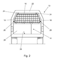
Figure 2 is a schematic end view of a vehicle having the partition ofFigure 1 ; -
Figure 3 is a section view of a vehicle roof lining mounting of the partition ofFigure 1 ; -
Figure 4 is a section view of a vehicle side wall mounting of the partition ofFigure 1 ; -
Figure 5 is a detailed section view of the mounting ofFigure 3 showing the mounting pin in its engaged position; -
Figure 6 is a detailed section view of the mounting pin ofFigure 5 showing the mounting pin in its emergency retracted position. - In
Figure 1 , avehicle 10 is shown having a passenger compartment 12 and aluggage compartment 14. Situated between theluggage compartment 14 and the passenger compartment 12 is apartition 16. - Turning to
Figure 2 , thepartition 16 is fixed to thevehicle walls 18 bywall mounting points 20 and to thevehicle roof 22 byroof mounting points 24. It will be appreciated that theroof mounting points 24 are vertically orientated whilst thewall mounting points 20 are horizontally orientated. It will also be appreciated that the specific position of the wall androof mounting points partition 16 could extend down to theluggage compartment floor 26 and be provided with floor mounting points. - Turning to
Figure 3 which shows theroof mounting point 24 in greater detail, thevehicle roof 22 has an inwardly extending portion which forms a roof bow which locally reinforces the vehicle roof and provides asuitable mounting 32 for thepartition 16. Themounting 32 is provided with amounting aperture 34 for receiving amounting pin 36. Themounting pin 36 is attached to the partition 16 (not shown inFigure 3 for clarity) via atube 38. The mountingpin 36 has a threaded section indicated generally at 40 on which is carried alocking nut 42 the purpose of which will be described in further detail shortly. As can be seen, thelocking nut 42 abuts an end of thetube 38. - At the opposite end of the
mounting pin 36 to thetube 38 is a projectinghead 44 which extends through theaperture 34. The projectinghead 44 has anannular depression 46 the purpose of which will be described in further detail shortly. On the opposite side of theaperture 34 to theannular depression 46 is anannular abutment 48 which in use rests against aninternal surface 50 of themounting 32. Arranged on the inboard side of themounting 32 is aheadlining trim 52. The headlining trim has a hole therethrough formed by themounting pin 36 having been pushed through theheadlining trim 52 in order to access themounting 32 as will be described in further detail shortly. - Prior to insertion of the
mounting pin 36 into themounting 32, theheadlining trim 52 entirely covers themounting 32. A locally weakened area may be provided in theheadlining trim 52 so as to allow the mountingpin 36 to more readily rupture the trim, thereby forming thehole 54 so as to access themounting 32. It will be appreciated that the projectinghead 44 has a chamfered end so as to promote a clean break in the trim. - Turning now to
Figure 4 , the vehiclewall mounting point 20 is shown to be similar to theroof mounting point 24 ofFigure 3 and accordingly components in common with the roof mounting points are similarly numbered. - In distinction from the
roof mounting point 24, thewall mounting point 20 has a different mounting pin 36' which has a greater distance between theannular abutment 48 and theannular depression 46 so as to accommodate the luggagecompartment trim piece 56 which is covered byluggage trim cover 57. The luggagecompartment trim piece 56 rests against a vehicle inner body panel mounting 32'. In all other regards, thewall mounting point 20 is identical to theroof mounting point 24 described above. - In order to fit the
partition 16, thelocking nuts 42 are rotated so that themounting pin 36, 36' are in their fully retracted positions. Each of thewall mounting points 20 androof mounting points 24 are then aligned with theirrespective mountings 32, 32' in the body side inner 58 androof 22 respectively. Themounting pins 36, 36' can be easily located at their respective mounting points by a discrete mark in the roof lining or luggage compartment trim pieces (these marks are not shown for clarity) or by the markings provided by the optional areas of pre-weakening. With the mounting pins in the correct position, thelocking nuts 42 are rotated so as to extend the projectinghead 44 of themounting pins 36, 36' which in turn causes the pins to penetrate respectively the luggagecompartment trim pieces 56 and roof lining, thereby providing access for the annular abutments to theinner surface 50 of themountings 32, 32'. Further rotation of the lockingnuts 42 causes theannular abutments 48 to be resiliently loaded against the mountingbrackets 32, 32' which fixes thepartition 16 firmly in place. - In the event of a vehicle collision or other event causing a sudden loading of the
partition 16 mountingpin 36, 36' may be moved from a rest engaged position as shown inFigure 5 in which thepartition 16 is resiliently held in place as described above, to an emergency position as shown inFigure 6 . In this position, a large load applied to thepartition 16 has caused theabutment 48 to withdraw from theinternal surface 50 of the mounting 32. However, rather than the entire mountingpin 36 being withdrawn or extracted from the mounting 32, theannular depression 46 has engaged with the mounting 32 so as to prevent complete retraction of the mountingpin 36 from the mounting. In this way, even in the event of a load on thepartition 16, the partition will not be entirely withdrawn from themountings 32, 32' and will therefore remain in position so as to safely retain the contents of theluggage compartment 14. - Additionally, each of the mounting has the same design. Likewise each of the mounting pins are similarly configured, subject to the distance between the annular depression and the abutment varying depending on the depth of trim. This provides the advantage that the plugs can all be the same size.
- It can also be envisaged within the scope of the invention that only on of an opposing pair of mounting
pins 36, 36' would be threaded, i.e. one could be of fixed geometry with the opposing pin providing the means to extend the projectinghead 44. Alternatively, thetubes 38 are threaded and may be turned by the user to extend or retract the mounting pins 36, 36' relative to thepartition 16. - In the event that the owner of the
vehicle 10 wishes to remove thepartition 16 from the vehicle, the lockingnuts 42 are simply unscrewed so as to release the mounting pins 36 from theroof bow 32, 32' and plastic plugs or caps are then inserted into the aperture so as to conceal thehole 54 in the headlining or luggage compartmenttrim pieces 56. - It will be appreciated that whilst the above description is an example of a partition of the present invention which separates the passenger compartment from the luggage compartment, the partition could equally well divide the luggage compartment of a passenger car, or the cargo area of a commercial vehicle without departure from the scope of the invention.
Claims (8)
- A partition mounting for a vehicle partition, the mounting adapted to receive a partition mounting pin, the partition mounting comprising an aperture for receiving the mounting pin, wherein the aperture is covered by a vehicle trim before insertion of the mounting pin into the mounting.
- A partition mounting according to claim 1 wherein the vehicle trim has a mark indicating the location of the mounting.
- A partition mounting according to claim 1 or 2 wherein the locking pin has an abutment for abutting the mounting.
- A partition mounting according to claim 3 wherein the mounting pin can be extended from the partition by rotation of a threaded nut on a threaded portion of the mounting pin.
- A partition mounting according to any preceding claim wherein the mounting pin has an annular depression for engaging the mounting in the event of the partition is loaded.
- A partition mounting according to any preceding claim wherein the vehicle trim has a locally weakened area concentric with the mounting so as to allow easy penetration of the trim by the mounting pin.
- A vehicle partition having a mounting pin for engaging the partition mounting of any one of claims 1 to 6 wherein the pin defines an annular depression for engaging the partition mounting in the event that the partition experiences a load or impact.
- A method of attaching a partition to a vehicle body, the method including the steps of:providing a mounting pin on the partition and a mounting on the vehicle body;providing a vehicle trim to cover the mounting;positioning the mounting pin adjacent the mounting;penetrating the trim with the mounting pin so as to engage the mounting with the mounting pin.
Applications Claiming Priority (1)
| Application Number | Priority Date | Filing Date | Title |
|---|---|---|---|
| GB0814010A GB2462295A (en) | 2008-07-31 | 2008-07-31 | Vehicle partition. |
Publications (2)
| Publication Number | Publication Date |
|---|---|
| EP2149479A1 true EP2149479A1 (en) | 2010-02-03 |
| EP2149479B1 EP2149479B1 (en) | 2012-02-01 |
Family
ID=39767288
Family Applications (1)
| Application Number | Title | Priority Date | Filing Date |
|---|---|---|---|
| EP09166291A Not-in-force EP2149479B1 (en) | 2008-07-31 | 2009-07-24 | Vehicle partition |
Country Status (4)
| Country | Link |
|---|---|
| EP (1) | EP2149479B1 (en) |
| AT (1) | ATE543695T1 (en) |
| ES (1) | ES2387051T3 (en) |
| GB (1) | GB2462295A (en) |
Citations (6)
| Publication number | Priority date | Publication date | Assignee | Title |
|---|---|---|---|---|
| FR2379407A1 (en) * | 1977-02-03 | 1978-09-01 | Vandamme Georges | Car passenger compartment transverse partition - has trellis assembly held by rod sliding to correct body width with bracket support and with flexible side supports |
| FR2395864A1 (en) * | 1977-06-29 | 1979-01-26 | Vandamme Georges | Car passenger compartment transverse partition - has trellis assembly held by rod sliding to correct body width with bracket support and with flexible side supports |
| GB2277060A (en) | 1993-04-16 | 1994-10-19 | Athag Ltd | A barrier for use in a vehicle |
| DE19730802C1 (en) * | 1997-07-18 | 1998-10-22 | Baumeister & Ostler Gmbh Co | Safety net arrangement |
| DE10023403A1 (en) | 2000-05-12 | 2001-11-22 | Audi Ag | Fixing device for separation unit for vehicle interior; has at least one flat spring element and at least one holder opening for connection element, with spring element on side of holder opening |
| DE10222050A1 (en) | 2002-05-17 | 2003-11-27 | Volkswagen Ag | Mounting for attaching netting partition to vehicle roof comprises retaining plate with bore, though which bolt is inserted whose head is held in position by edge of spring-loaded sleeve |
Family Cites Families (1)
| Publication number | Priority date | Publication date | Assignee | Title |
|---|---|---|---|---|
| GB2335630A (en) * | 1998-03-13 | 1999-09-29 | Asg | Internal vehicle partition assembly |
-
2008
- 2008-07-31 GB GB0814010A patent/GB2462295A/en not_active Withdrawn
-
2009
- 2009-07-24 ES ES09166291T patent/ES2387051T3/en active Active
- 2009-07-24 EP EP09166291A patent/EP2149479B1/en not_active Not-in-force
- 2009-07-24 AT AT09166291T patent/ATE543695T1/en active
Patent Citations (6)
| Publication number | Priority date | Publication date | Assignee | Title |
|---|---|---|---|---|
| FR2379407A1 (en) * | 1977-02-03 | 1978-09-01 | Vandamme Georges | Car passenger compartment transverse partition - has trellis assembly held by rod sliding to correct body width with bracket support and with flexible side supports |
| FR2395864A1 (en) * | 1977-06-29 | 1979-01-26 | Vandamme Georges | Car passenger compartment transverse partition - has trellis assembly held by rod sliding to correct body width with bracket support and with flexible side supports |
| GB2277060A (en) | 1993-04-16 | 1994-10-19 | Athag Ltd | A barrier for use in a vehicle |
| DE19730802C1 (en) * | 1997-07-18 | 1998-10-22 | Baumeister & Ostler Gmbh Co | Safety net arrangement |
| DE10023403A1 (en) | 2000-05-12 | 2001-11-22 | Audi Ag | Fixing device for separation unit for vehicle interior; has at least one flat spring element and at least one holder opening for connection element, with spring element on side of holder opening |
| DE10222050A1 (en) | 2002-05-17 | 2003-11-27 | Volkswagen Ag | Mounting for attaching netting partition to vehicle roof comprises retaining plate with bore, though which bolt is inserted whose head is held in position by edge of spring-loaded sleeve |
Also Published As
| Publication number | Publication date |
|---|---|
| EP2149479B1 (en) | 2012-02-01 |
| GB0814010D0 (en) | 2008-09-10 |
| ES2387051T3 (en) | 2012-09-12 |
| GB2462295A (en) | 2010-02-03 |
| ATE543695T1 (en) | 2012-02-15 |
Similar Documents
| Publication | Publication Date | Title |
|---|---|---|
| US8419117B2 (en) | Means for accessing a vehicle in an emergency | |
| US6983970B2 (en) | Frameless load restraining vehicular barrier device | |
| CN204488654U (en) | Vehicle and extensible pedal assembly | |
| US20100164196A1 (en) | Telescoping Vehicle Step | |
| US20080106058A1 (en) | Detachable dual-use platform apparatus and method | |
| CN108791090B (en) | Cargo compartment components for motor vehicles | |
| US20130320694A1 (en) | Integrated cargo area container system | |
| US20100140996A1 (en) | Auxiliary seat for a motor vehicle | |
| US20140341634A1 (en) | Anchor point in a motor vehicle | |
| US9981516B1 (en) | Automatic ejecting and retracting trailer hitch | |
| GB2554541A (en) | Device for fastening a catch net in a vehicle | |
| US9296351B1 (en) | Cargo area airbag | |
| US10081331B2 (en) | Fastening arrangement for a safety belt of a rear seat row of a motor vehicle and motor vehicle with such a fastening arrangement | |
| US7300090B2 (en) | Split seat stowage system | |
| EP2149479B1 (en) | Vehicle partition | |
| US9676341B2 (en) | Center console for a motor vehicle and motor vehicle having such a center console | |
| DE202015008710U1 (en) | Motor vehicle with a device for fixing a warning triangle | |
| US20160046177A1 (en) | Vehicle | |
| EP2080692B1 (en) | A bulkhead for a motor vehicle | |
| FR3075127A1 (en) | CENTER CONSOLE WITH POSITION MODIFIABLE BY SWITCHING INTO AN INFLATABLE PROTECTIVE BAG FOR A VEHICLE WITH A DISORIENTABLE SEAT (S) | |
| DE10207485B4 (en) | Folding seat for commercial vehicles | |
| US8113566B2 (en) | Loading space cover | |
| CN206501796U (en) | Bicycle tray system and motor vehicles for vehicle | |
| EP3810461B1 (en) | Device for protecting a passenger side safety airbag for a motor vehicle | |
| EP2340798A1 (en) | Transport vehicle provided with a space for accommodating a wheelchair user |
Legal Events
| Date | Code | Title | Description |
|---|---|---|---|
| PUAI | Public reference made under article 153(3) epc to a published international application that has entered the european phase |
Free format text: ORIGINAL CODE: 0009012 |
|
| AK | Designated contracting states |
Kind code of ref document: A1 Designated state(s): AT BE BG CH CY CZ DE DK EE ES FI FR GB GR HR HU IE IS IT LI LT LU LV MC MK MT NL NO PL PT RO SE SI SK SM TR |
|
| AX | Request for extension of the european patent |
Extension state: AL BA RS |
|
| 17P | Request for examination filed |
Effective date: 20100803 |
|
| GRAP | Despatch of communication of intention to grant a patent |
Free format text: ORIGINAL CODE: EPIDOSNIGR1 |
|
| RIC1 | Information provided on ipc code assigned before grant |
Ipc: F16B 35/04 20060101ALI20110622BHEP Ipc: F16B 21/16 20060101ALI20110622BHEP Ipc: B60R 21/02 20060101AFI20110622BHEP Ipc: F16B 35/06 20060101ALI20110622BHEP Ipc: B60R 13/02 20060101ALI20110622BHEP |
|
| GRAS | Grant fee paid |
Free format text: ORIGINAL CODE: EPIDOSNIGR3 |
|
| GRAA | (expected) grant |
Free format text: ORIGINAL CODE: 0009210 |
|
| AK | Designated contracting states |
Kind code of ref document: B1 Designated state(s): AT BE BG CH CY CZ DE DK EE ES FI FR GB GR HR HU IE IS IT LI LT LU LV MC MK MT NL NO PL PT RO SE SI SK SM TR |
|
| REG | Reference to a national code |
Ref country code: GB Ref legal event code: FG4D |
|
| REG | Reference to a national code |
Ref country code: AT Ref legal event code: REF Ref document number: 543695 Country of ref document: AT Kind code of ref document: T Effective date: 20120215 Ref country code: CH Ref legal event code: EP |
|
| REG | Reference to a national code |
Ref country code: DE Ref legal event code: R096 Ref document number: 602009005003 Country of ref document: DE Effective date: 20120405 |
|
| REG | Reference to a national code |
Ref country code: NL Ref legal event code: VDEP Effective date: 20120201 |
|
| LTIE | Lt: invalidation of european patent or patent extension |
Effective date: 20120201 |
|
| PG25 | Lapsed in a contracting state [announced via postgrant information from national office to epo] |
Ref country code: HR Free format text: LAPSE BECAUSE OF FAILURE TO SUBMIT A TRANSLATION OF THE DESCRIPTION OR TO PAY THE FEE WITHIN THE PRESCRIBED TIME-LIMIT Effective date: 20120201 Ref country code: NO Free format text: LAPSE BECAUSE OF FAILURE TO SUBMIT A TRANSLATION OF THE DESCRIPTION OR TO PAY THE FEE WITHIN THE PRESCRIBED TIME-LIMIT Effective date: 20120501 Ref country code: NL Free format text: LAPSE BECAUSE OF FAILURE TO SUBMIT A TRANSLATION OF THE DESCRIPTION OR TO PAY THE FEE WITHIN THE PRESCRIBED TIME-LIMIT Effective date: 20120201 Ref country code: IS Free format text: LAPSE BECAUSE OF FAILURE TO SUBMIT A TRANSLATION OF THE DESCRIPTION OR TO PAY THE FEE WITHIN THE PRESCRIBED TIME-LIMIT Effective date: 20120601 Ref country code: LT Free format text: LAPSE BECAUSE OF FAILURE TO SUBMIT A TRANSLATION OF THE DESCRIPTION OR TO PAY THE FEE WITHIN THE PRESCRIBED TIME-LIMIT Effective date: 20120201 |
|
| PG25 | Lapsed in a contracting state [announced via postgrant information from national office to epo] |
Ref country code: PT Free format text: LAPSE BECAUSE OF FAILURE TO SUBMIT A TRANSLATION OF THE DESCRIPTION OR TO PAY THE FEE WITHIN THE PRESCRIBED TIME-LIMIT Effective date: 20120601 Ref country code: BE Free format text: LAPSE BECAUSE OF FAILURE TO SUBMIT A TRANSLATION OF THE DESCRIPTION OR TO PAY THE FEE WITHIN THE PRESCRIBED TIME-LIMIT Effective date: 20120201 Ref country code: GR Free format text: LAPSE BECAUSE OF FAILURE TO SUBMIT A TRANSLATION OF THE DESCRIPTION OR TO PAY THE FEE WITHIN THE PRESCRIBED TIME-LIMIT Effective date: 20120502 Ref country code: PL Free format text: LAPSE BECAUSE OF FAILURE TO SUBMIT A TRANSLATION OF THE DESCRIPTION OR TO PAY THE FEE WITHIN THE PRESCRIBED TIME-LIMIT Effective date: 20120201 Ref country code: LV Free format text: LAPSE BECAUSE OF FAILURE TO SUBMIT A TRANSLATION OF THE DESCRIPTION OR TO PAY THE FEE WITHIN THE PRESCRIBED TIME-LIMIT Effective date: 20120201 Ref country code: FI Free format text: LAPSE BECAUSE OF FAILURE TO SUBMIT A TRANSLATION OF THE DESCRIPTION OR TO PAY THE FEE WITHIN THE PRESCRIBED TIME-LIMIT Effective date: 20120201 |
|
| REG | Reference to a national code |
Ref country code: ES Ref legal event code: FG2A Ref document number: 2387051 Country of ref document: ES Kind code of ref document: T3 Effective date: 20120912 |
|
| REG | Reference to a national code |
Ref country code: AT Ref legal event code: MK05 Ref document number: 543695 Country of ref document: AT Kind code of ref document: T Effective date: 20120201 |
|
| PG25 | Lapsed in a contracting state [announced via postgrant information from national office to epo] |
Ref country code: CY Free format text: LAPSE BECAUSE OF FAILURE TO SUBMIT A TRANSLATION OF THE DESCRIPTION OR TO PAY THE FEE WITHIN THE PRESCRIBED TIME-LIMIT Effective date: 20120201 |
|
| PG25 | Lapsed in a contracting state [announced via postgrant information from national office to epo] |
Ref country code: SI Free format text: LAPSE BECAUSE OF FAILURE TO SUBMIT A TRANSLATION OF THE DESCRIPTION OR TO PAY THE FEE WITHIN THE PRESCRIBED TIME-LIMIT Effective date: 20120201 Ref country code: DK Free format text: LAPSE BECAUSE OF FAILURE TO SUBMIT A TRANSLATION OF THE DESCRIPTION OR TO PAY THE FEE WITHIN THE PRESCRIBED TIME-LIMIT Effective date: 20120201 Ref country code: RO Free format text: LAPSE BECAUSE OF FAILURE TO SUBMIT A TRANSLATION OF THE DESCRIPTION OR TO PAY THE FEE WITHIN THE PRESCRIBED TIME-LIMIT Effective date: 20120201 Ref country code: EE Free format text: LAPSE BECAUSE OF FAILURE TO SUBMIT A TRANSLATION OF THE DESCRIPTION OR TO PAY THE FEE WITHIN THE PRESCRIBED TIME-LIMIT Effective date: 20120201 Ref country code: SE Free format text: LAPSE BECAUSE OF FAILURE TO SUBMIT A TRANSLATION OF THE DESCRIPTION OR TO PAY THE FEE WITHIN THE PRESCRIBED TIME-LIMIT Effective date: 20120201 Ref country code: CZ Free format text: LAPSE BECAUSE OF FAILURE TO SUBMIT A TRANSLATION OF THE DESCRIPTION OR TO PAY THE FEE WITHIN THE PRESCRIBED TIME-LIMIT Effective date: 20120201 |
|
| PG25 | Lapsed in a contracting state [announced via postgrant information from national office to epo] |
Ref country code: SK Free format text: LAPSE BECAUSE OF FAILURE TO SUBMIT A TRANSLATION OF THE DESCRIPTION OR TO PAY THE FEE WITHIN THE PRESCRIBED TIME-LIMIT Effective date: 20120201 Ref country code: IT Free format text: LAPSE BECAUSE OF FAILURE TO SUBMIT A TRANSLATION OF THE DESCRIPTION OR TO PAY THE FEE WITHIN THE PRESCRIBED TIME-LIMIT Effective date: 20120201 |
|
| PLBE | No opposition filed within time limit |
Free format text: ORIGINAL CODE: 0009261 |
|
| STAA | Information on the status of an ep patent application or granted ep patent |
Free format text: STATUS: NO OPPOSITION FILED WITHIN TIME LIMIT |
|
| 26N | No opposition filed |
Effective date: 20121105 |
|
| PG25 | Lapsed in a contracting state [announced via postgrant information from national office to epo] |
Ref country code: AT Free format text: LAPSE BECAUSE OF FAILURE TO SUBMIT A TRANSLATION OF THE DESCRIPTION OR TO PAY THE FEE WITHIN THE PRESCRIBED TIME-LIMIT Effective date: 20120201 |
|
| PG25 | Lapsed in a contracting state [announced via postgrant information from national office to epo] |
Ref country code: MC Free format text: LAPSE BECAUSE OF NON-PAYMENT OF DUE FEES Effective date: 20120731 Ref country code: MK Free format text: LAPSE BECAUSE OF FAILURE TO SUBMIT A TRANSLATION OF THE DESCRIPTION OR TO PAY THE FEE WITHIN THE PRESCRIBED TIME-LIMIT Effective date: 20120201 |
|
| REG | Reference to a national code |
Ref country code: DE Ref legal event code: R097 Ref document number: 602009005003 Country of ref document: DE Effective date: 20121105 |
|
| REG | Reference to a national code |
Ref country code: FR Ref legal event code: ST Effective date: 20130329 |
|
| PG25 | Lapsed in a contracting state [announced via postgrant information from national office to epo] |
Ref country code: FR Free format text: LAPSE BECAUSE OF NON-PAYMENT OF DUE FEES Effective date: 20120731 |
|
| REG | Reference to a national code |
Ref country code: IE Ref legal event code: MM4A |
|
| PG25 | Lapsed in a contracting state [announced via postgrant information from national office to epo] |
Ref country code: IE Free format text: LAPSE BECAUSE OF NON-PAYMENT OF DUE FEES Effective date: 20120724 Ref country code: MT Free format text: LAPSE BECAUSE OF FAILURE TO SUBMIT A TRANSLATION OF THE DESCRIPTION OR TO PAY THE FEE WITHIN THE PRESCRIBED TIME-LIMIT Effective date: 20120201 Ref country code: BG Free format text: LAPSE BECAUSE OF FAILURE TO SUBMIT A TRANSLATION OF THE DESCRIPTION OR TO PAY THE FEE WITHIN THE PRESCRIBED TIME-LIMIT Effective date: 20120501 |
|
| PGFP | Annual fee paid to national office [announced via postgrant information from national office to epo] |
Ref country code: DE Payment date: 20130517 Year of fee payment: 5 |
|
| REG | Reference to a national code |
Ref country code: CH Ref legal event code: PL |
|
| PG25 | Lapsed in a contracting state [announced via postgrant information from national office to epo] |
Ref country code: CH Free format text: LAPSE BECAUSE OF NON-PAYMENT OF DUE FEES Effective date: 20130731 Ref country code: LI Free format text: LAPSE BECAUSE OF NON-PAYMENT OF DUE FEES Effective date: 20130731 Ref country code: TR Free format text: LAPSE BECAUSE OF FAILURE TO SUBMIT A TRANSLATION OF THE DESCRIPTION OR TO PAY THE FEE WITHIN THE PRESCRIBED TIME-LIMIT Effective date: 20120201 |
|
| PG25 | Lapsed in a contracting state [announced via postgrant information from national office to epo] |
Ref country code: LU Free format text: LAPSE BECAUSE OF NON-PAYMENT OF DUE FEES Effective date: 20120724 Ref country code: SM Free format text: LAPSE BECAUSE OF FAILURE TO SUBMIT A TRANSLATION OF THE DESCRIPTION OR TO PAY THE FEE WITHIN THE PRESCRIBED TIME-LIMIT Effective date: 20120201 |
|
| PG25 | Lapsed in a contracting state [announced via postgrant information from national office to epo] |
Ref country code: HU Free format text: LAPSE BECAUSE OF FAILURE TO SUBMIT A TRANSLATION OF THE DESCRIPTION OR TO PAY THE FEE WITHIN THE PRESCRIBED TIME-LIMIT Effective date: 20090724 |
|
| PGFP | Annual fee paid to national office [announced via postgrant information from national office to epo] |
Ref country code: GB Payment date: 20140702 Year of fee payment: 6 Ref country code: ES Payment date: 20140710 Year of fee payment: 6 |
|
| REG | Reference to a national code |
Ref country code: DE Ref legal event code: R119 Ref document number: 602009005003 Country of ref document: DE |
|
| PG25 | Lapsed in a contracting state [announced via postgrant information from national office to epo] |
Ref country code: DE Free format text: LAPSE BECAUSE OF NON-PAYMENT OF DUE FEES Effective date: 20150203 |
|
| REG | Reference to a national code |
Ref country code: DE Ref legal event code: R119 Ref document number: 602009005003 Country of ref document: DE Effective date: 20150203 |
|
| GBPC | Gb: european patent ceased through non-payment of renewal fee |
Effective date: 20150724 |
|
| PG25 | Lapsed in a contracting state [announced via postgrant information from national office to epo] |
Ref country code: GB Free format text: LAPSE BECAUSE OF NON-PAYMENT OF DUE FEES Effective date: 20150724 |
|
| REG | Reference to a national code |
Ref country code: ES Ref legal event code: FD2A Effective date: 20161229 |
|
| PG25 | Lapsed in a contracting state [announced via postgrant information from national office to epo] |
Ref country code: ES Free format text: LAPSE BECAUSE OF NON-PAYMENT OF DUE FEES Effective date: 20150725 |