EP2149477A2 - Système d'assemblage pour monter un dispositif électronique sur un véhicule - Google Patents
Système d'assemblage pour monter un dispositif électronique sur un véhicule Download PDFInfo
- Publication number
- EP2149477A2 EP2149477A2 EP09166172A EP09166172A EP2149477A2 EP 2149477 A2 EP2149477 A2 EP 2149477A2 EP 09166172 A EP09166172 A EP 09166172A EP 09166172 A EP09166172 A EP 09166172A EP 2149477 A2 EP2149477 A2 EP 2149477A2
- Authority
- EP
- European Patent Office
- Prior art keywords
- engaging member
- keeper
- removable device
- retainer
- mounting system
- Prior art date
- Legal status (The legal status is an assumption and is not a legal conclusion. Google has not performed a legal analysis and makes no representation as to the accuracy of the status listed.)
- Granted
Links
- 229920001971 elastomer Polymers 0.000 claims description 6
- 239000000806 elastomer Substances 0.000 claims description 3
- 239000011359 shock absorbing material Substances 0.000 claims 2
- 230000013011 mating Effects 0.000 claims 1
- 238000009434 installation Methods 0.000 description 6
- 230000035939 shock Effects 0.000 description 4
- 239000000853 adhesive Substances 0.000 description 3
- 230000001070 adhesive effect Effects 0.000 description 3
- 229920002430 Fibre-reinforced plastic Polymers 0.000 description 2
- 238000013459 approach Methods 0.000 description 2
- 239000002131 composite material Substances 0.000 description 2
- 239000011151 fibre-reinforced plastic Substances 0.000 description 2
- 238000007373 indentation Methods 0.000 description 2
- 238000000034 method Methods 0.000 description 2
- 239000004033 plastic Substances 0.000 description 2
- 229920003023 plastic Polymers 0.000 description 2
- 230000001960 triggered effect Effects 0.000 description 2
- CWYNVVGOOAEACU-UHFFFAOYSA-N Fe2+ Chemical group [Fe+2] CWYNVVGOOAEACU-UHFFFAOYSA-N 0.000 description 1
- 230000002411 adverse Effects 0.000 description 1
- 229910045601 alloy Inorganic materials 0.000 description 1
- 239000000956 alloy Substances 0.000 description 1
- 230000003466 anti-cipated effect Effects 0.000 description 1
- 238000010276 construction Methods 0.000 description 1
- 230000001419 dependent effect Effects 0.000 description 1
- 238000006073 displacement reaction Methods 0.000 description 1
- 230000000694 effects Effects 0.000 description 1
- 238000011900 installation process Methods 0.000 description 1
- 239000000463 material Substances 0.000 description 1
- 239000002184 metal Substances 0.000 description 1
- 229910001092 metal group alloy Inorganic materials 0.000 description 1
- 238000005065 mining Methods 0.000 description 1
- 229920000642 polymer Polymers 0.000 description 1
- 230000002035 prolonged effect Effects 0.000 description 1
- 239000012858 resilient material Substances 0.000 description 1
Images


Classifications
-
- B—PERFORMING OPERATIONS; TRANSPORTING
- B60—VEHICLES IN GENERAL
- B60R—VEHICLES, VEHICLE FITTINGS, OR VEHICLE PARTS, NOT OTHERWISE PROVIDED FOR
- B60R11/00—Arrangements for holding or mounting articles, not otherwise provided for
- B60R11/02—Arrangements for holding or mounting articles, not otherwise provided for for radio sets, television sets, telephones, or the like; Arrangement of controls thereof
- B60R11/0258—Arrangements for holding or mounting articles, not otherwise provided for for radio sets, television sets, telephones, or the like; Arrangement of controls thereof for navigation systems
-
- H—ELECTRICITY
- H01—ELECTRIC ELEMENTS
- H01Q—ANTENNAS, i.e. RADIO AERIALS
- H01Q1/00—Details of, or arrangements associated with, antennas
- H01Q1/12—Supports; Mounting means
- H01Q1/1207—Supports; Mounting means for fastening a rigid aerial element
- H01Q1/1221—Supports; Mounting means for fastening a rigid aerial element onto a wall
Definitions
- This invention relates to a mounting system for mounting an electronic device on a vehicle.
- Location-determining receivers, sensors and other electronic devices are commonly mounted on agricultural vehicles to provide ground position information to a variety of precision agriculture applications.
- location-determining receivers e.g., global positioning system (GPS) receivers
- GPS global positioning system
- Cantilever mounting imposes weight limits for the device.
- certain cantilevered devices are susceptible to high levels of shock, vibration or other displacement or movement, which can have adverse effects on the accuracy of position information provided by the location-determining receiver.
- Another disadvantage to current cantilever mounting systems is presented by the installation process for securing a device to a vehicle that generally requires two hands.
- a mounting system for mounting an electronic device on a vehicle includes a mounting bracket that can be attached to a vehicle.
- the mounting bracket has a first member defining an engaging member and a second member defining a keeper.
- the mounting system also includes a retainer attached to the electronic device and capable of engaging and rotating around the engaging member.
- the mounting system includes a latch associated with the electronic device.
- the latch comprises a rotor capable of engaging the keeper and securing the electronic device to the mounting bracket during or after the retainer has engaged the engaging member.
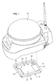
- a mounting system 11 for securely mounting a removable device 22 (e.g., an electronic device or location-determining receiver) to a vehicle using a mounting bracket 12 securely attached to a vehicle (not shown).
- a removable device 22 e.g., an electronic device or location-determining receiver
- the removable device 22 is associated with a retainer 14 and a latch 15.
- the mounting bracket 12 comprises an engaging member 18 and a keeper 16.
- the retainer 14 is capable of receiving or engaging the engaging member 18.
- a first state e.g., in an open state
- the retainer 14 and the engaging member 18 form a hinge or define a rotational axis about which the retainer 14 and the removable device 22 can rotate.
- the rotation of the retainer 14 about the engaging member 18 allows the removable device 22 to be positioned (or rotated) such that the latch 15 engages the keeper 16.
- the removable device 22 is any device that may be removably mounted to a vehicle.
- the removable device 22 is a location-determining receiver or a global positioning system (GPS) receiver.
- GPS global positioning system
- the removable device 22 may be another type of electronic device or a sensor in alternative embodiments.
- vehicle is anticipated to be a tractor, combine, or other agricultural vehicle.
- vehicle may refer to an agricultural implement, construction vehicle, forestry vehicle, mining equipment, truck, military vehicle, train, aircraft, ship, vessel, watercraft or other vehicle that may require installation of an electronic device.
- vehicle may be another type of vehicle in alternative embodiments.
- the mounting bracket 12 comprises an engaging member 18 and a keeper 16.
- the engaging member 18 is generally parallel to the keeper 16, although in an alternative embodiment the engaging member 18 or the keeper 16 may be curved; hence, the engaging member 18 and the keeper 16 may exist in a non-parallel configuration.
- the engaging member 18 and keeper 16 are generally cylindrical or each has an interface or portion with a generally cylindrical cross section.
- the engaging member 18 and the keeper 16 may be connected by a first side 21 that is generally perpendicular to the engaging member 18 and the keeper 16.
- the engaging member 18 and the keeper 16 may be connected by a second side 23 that is generally perpendicular to the engaging member 18 and the keeper 16.
- the first side 21 and the second side 23 are generally parallel to each other, although in an alternative embodiment the first side 21 and the second side 23 may be curved; hence, the first side 21 and the second side 23 may exist in a non-parallel configuration.
- a flange 25 is included in at least part of the spatial area bounded by the engaging member 18, keeper 16, first side 21, and second side 23.
- the flange 25 includes mounting holes 20 for attaching the mounting bracket 12 to the vehicle.
- the mounting bracket 12 may be composed of plastic, metal, alloy, polymer, composite material, fiber-reinforced plastic, fiber-reinforced polymer or any other suitable material.
- mounting bracket 12 is symmetrical such that the engaging member 18 and the keeper 16 have substantially similar cross sectional dimensions or configurations.
- the engaging member 18 and keeper 16 may be generally uniform in size and shape.
- Such symmetry allows the mounting bracket 12, whose keeper 16 may potentially experience wear with prolonged use, to be removed from the vehicle, rotated 180 degrees, and reattached to the vehicle. Once the mounting bracket 12 has been rotated and reattached, the engaging member 18 performs the role of keeper 16, and the keeper 16 performs the role of the engaging member 18.
- the retainer 14 is an integral part of the structure of the removable device 22.
- the retainer 14 comprises a molded tab extending from the removable device 22, and a recess is formed between the retainer 14 and a surface (e.g. outer surface) of the removable device 22.
- Installation of the removable device 22 on the vehicle may involve inserting the retainer 14 under or partially around the engaging member 18.
- the combination of the retainer 14 and the engaging member 18 forms a hinge or rotational axis in which the retainer 14 at least partially encircles the engaging member 18.
- the engaging member 18 forms a rotational axis about which the retainer 14 and the removable device 22 can rotate. Rotation of the retainer 14 about the engaging member 18 allows the latch 15 to engage the keeper 16.
- the retainer 14 comprises a bracket that is separate from the removable device 22.
- the bracket is secured to the removable device 22 by fasteners, adhesives, connectors, or otherwise.
- Use of a separate bracket allows an existing removable device 22 to be adapted to use the mounting system 11.
- a recess is formed between the retainer 14 and a surface of the removable device 22.
- Installation of the removable device 22 on the vehicle may involve inserting the retainer 14 under or partially around the engaging member 18.
- the combination of the retainer 14 and the engaging member 18 forms a hinge or rotational axis in which the retainer 14 at least partially encircles the engaging member 18.
- the engaging member 18 forms a rotational axis about which the retainer 14 and the removable device 22 can rotate. Rotation of the retainer 14 about the engaging member 18 allows the latch 15 to engage the keeper 16.
- the retainer 14 may comprise an uninterrupted tab whose length is approximately equal to the length of the engaging member 18. Further, the retainer 14 is of sufficient length to prevent lateral torsional movement of the removable device 22 once the retainer 14 has engaged the engaging member 18 and the latch 15 has engaged the keeper 16.
- retainer 14 has a length that is less than the length of the engaging member 18. In this embodiment, the length of the retainer 14 is sufficient to prevent lateral torsional movement of the removable device 22 once the retainer 14 has engaged the engaging member 18 and the latch 15 has engaged the keeper 16. For example, a retainer 14 whose length is at least half of the length of the engaging member 18 is sufficient to prevent lateral torsional movement of the removable device 22.
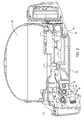
- the latch 15 is a standard rotary latch which comprises a rotor 17, rotor spring 32, pawl 19, pawl spring 30, and release lever 26.
- the rotor 17 and rotor spring 32 are pivotally mounted to the removable device 22 about a shaft 34 associated with the removable device 22.
- the pawl 19 and pawl spring 30 are similarly pivotally mounted to the removable device 22 about a shaft 34 associated with the removable device 22.
- the rotor 17 is spring loaded by rotor spring 32 toward an open position. When the rotor 17 engages the keeper 16, the rotor 17 rotates to partially encircle the keeper 16.
- the pawl 19 also engages the rotor 17, holding the rotor 17 in a closed position.
- the pawl 19 is spring loaded by pawl spring 30 toward a direction that presses the pawl 19 against a notch 55 in the rotor 17, holding the rotor 17 in the closed position.
- a release lever 26 is attached to the pawl 19. To release the pawl 19, the biasing force of the pawl spring 30 and the rotor spring 32 must be overcome by application of force by a user.
- a manual latch is used.
- a single latch 15 engages the keeper 16, securing the removable device 22 to the mounting bracket 12.
- two or more latches 15 may be used, with each latch 15 engaging the keeper 16.
- Use of two or more latches 15 provides additional stability for the removable device 22, and provides redundancy to ensure that the removable device 22 remains securely attached to the mounting bracket 12.
- the release 26 To allow removal of the removable device 22, the release 26 must be accessible to an operator.
- the release 26 is situated inside an indentation 10.
- an indentation defines a handle that provides for a placement of the operator's hand that is convenient for the purposes of carrying, installing, and removing the removable device 22.
- the mounting system 11 may further comprise one or more isolators.
- An isolator may be rubber, elastomer, or any other suitable resilient material.
- the isolator comprises one or more resilient barbs, one end of which is inserted into a hole or other opening in a surface of the removable device 22 between the removable device 22 and the mounting bracket 12.
- the isolator comprises one or more resilient disks that are fastened (e.g., attached using screws or adhesive) to the removable device 22 between the removable device 22 and the mounting bracket 12.
- the isolator comprises a resilient sheet that is inserted between the removable device 22 and the mounting bracket 12 during assembly.
- the isolator contacts the removable device 22 prior to the rotor 17 of the latch 15 engaging the keeper 16, and the isolator is capable of being compressed during installation to allow the rotor 17 to engage the keeper 16.
- the isolator is capable of expanding to prevent vibration or other movement of the removable device 22 during operation of the vehicle.
- an isolator e.g., resilient isolator
- an isolator is inserted between the mounting bracket 12 and the vehicle to reduce shock and vibration transmitted to the device 22 during movement of the vehicle.
- removable device 22 is associated with a protrusion 28 that mates with a recess defined by the engaging member 18, keeper 16, and first side 21 and second side 23 of mounting bracket 12.
- the protrusion 28 comprises at least a first wall 36 and a second wall 38.
- the protrusion may further comprise one or more pads, ribs or strips 40 that lie between or interconnect the first wall 36 and the second wall 38.
- the protrusion 28 has a perimeter that is slightly smaller than the perimeter of the recess defined by the engaging member 18, keeper 16, and first side 21 and second side 23 of mounting bracket 12 such that the protrusion 28 fits securely in the recess defined by the engaging member 18, keeper 16, and first side 21 and second side 23 of mounting bracket 12, and lateral torsional movement of the removable device 22 is prevented.
- the protrusion 28 is generally rectangular, although the protrusion 28 may be another shape that fits securely in the recess defined by the engaging member 18, keeper 16, and first side 21 and second side 23 of mounting bracket 12, hence preventing lateral torsional movement of the removable device 22.
- first wall 36 and second wall 38 of protrusion 28 taper inwardly as the walls (36, 38) extend from the removable device 22.
- the tapered shape of the protrusion 28 aligns the protrusion 28 inside the recess defined by the engaging member 18, keeper 16, and first side 21 and second side 23 of mounting bracket 12, and lateral torsional movement of the removable device 22 is prevented.
- the protrusion 28 may comprise a generally polyhedral structure having the first wall 36 and the second wall 38 integrated into the polyhedral structure.
- the mounting bracket 12 is attached to the vehicle.
- the mounting bracket 12 is attached to the vehicle using screws, rivets, bolts, adhesive, or other attachment means. Once the mounting bracket 12 is attached to the vehicle, the removable device 22 can be installed on the vehicle and removed repeatedly without removing or reinstalling the mounting bracket 12.
- the latch 15 is in a first position (e.g. an open state).
- the isolator is in a first state (e.g., an uncompressed or expanded state).
- the retainer 14 is inserted into the engaging member 18, forming a hinge or rotational axis about which the retainer 14 and the removable device 22 can rotate.
- the removable device 22 is rotated about the engaging member 18.
- the isolator (if present) may exert pressure on the removable device 22 prior to engagement of the latch 15 to the keeper 16, and pressure may be applied by a user to compress the isolator (if present) and to allow the latch 15 to engage the keeper 16.
- the latch 15 When the latch 15 engages the keeper 16, the latch 15 rotates into a second position (e.g. a closed or locked state) and closes around the keeper 16.
- the release lever 26 holds the pawl 19 in a position such that the rotor 17 is held in the closed position encircling the keeper 16.
- the pawl 19 is held in such position and the removable device 22 thus remains securely fastened to the vehicle as long as the release 26 is not triggered.
- the isolator may expand, exerting pressure on the removable device 22, and preventing vibration or other movement of the removable device 22.
- the latch 15 When the latch 15 is in the closed or locked state, the removable device 22 is securely attached to the vehicle. Rotation of the retainer 14 and the removable device 22 about the engaging member 18 is prevented.
- the release 26 is triggered by a user. Triggering of the release 26 allows the pawl 19 to rotate, thus allowing the rotor 17 to rotate into the open position and allowing the removable device 22 to be removed from the mounting bracket by removing the retainer 14 from the engaging member 18.
- the mounting system 12 facilitates securely, but removably, attaching an electronic device to a vehicle using simple, one-handed installation and removal of the device without the use of tools or small hardware pieces.
- the mounting system 11 requires no magnet (for mounting) which could interfere with sensitive electronic equipment and which would require a ferrous structure on the vehicle.
- the mounting system 11 may be used advantageously in conjunction with metal alloy, plastic, polymeric or composite body panels or portions of a vehicle.
- a removable device 22 installed using the mounting system 11 may be removed from the vehicle with one hand and without the use of tools or separate hardware.
- the mounting bracket 12 is installed, the mounting system 11 enables consistent placement of the removable device 22 each time the removable device 22 is installed on the vehicle, which enables consistent location information to be provided to precision farming software for every installation when the removable device 22 is a location-determining receiver.
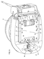
- the retainer 114 comprises two or more discrete hinge members rather than one continuous tab.
- the discrete hinge members comprise tabs that are separated by sufficient space to prevent lateral torsional movement of the removable device 22 once the retainer 114 has engaged the engaging member 118 and the latch 15 has engaged the keeper 116.
- placing the discrete hinge members such that the length defined by the outer ends of the hinge members is approximately equal to or greater than approximately one-half of the length of the engaging member 118 is sufficient to prevent lateral torsional movement of the removable device 22.
- the embodiment of FIG. 5 differs from the embodiment shown in FIG. 2 because the retainer 114 shown in FIG. 5 comprises discrete hinge members rather than comprising a continuous tab as shown by retainer 14 in FIG. 2 .
- the keeper 116 and the engaging member 118 may each comprise one or more interface members 27 (e.g., radial bushings) that are generally cylindrical and are associated (e.g., secured or rotationally connected) with the keeper 116 and the engaging member 118.
- the embodiment of FIG. 5 differs from the embodiment shown in FIG. 2 because the engaging member 118 and the keeper 116 shown in FIG. 5 comprise one or more engaging members 27 rather than comprising uniform, generally cylindrical members as shown by engaging member 18 and keeper 16 in FIG. 2 .
- the interface members 27 are optional and may be deleted from certain embodiments.
- the assembly process for the embodiment of FIG. 5 is identical to the assembly process for the embodiment shown in FIG. 2 .
Landscapes
- Engineering & Computer Science (AREA)
- Radar, Positioning & Navigation (AREA)
- Remote Sensing (AREA)
- Mechanical Engineering (AREA)
- Fittings On The Vehicle Exterior For Carrying Loads, And Devices For Holding Or Mounting Articles (AREA)
Applications Claiming Priority (1)
| Application Number | Priority Date | Filing Date | Title |
|---|---|---|---|
| US12/182,406 US8348112B2 (en) | 2008-07-30 | 2008-07-30 | Mounting system for mounting an electronic device on a vehicle |
Publications (3)
| Publication Number | Publication Date |
|---|---|
| EP2149477A2 true EP2149477A2 (fr) | 2010-02-03 |
| EP2149477A3 EP2149477A3 (fr) | 2012-05-09 |
| EP2149477B1 EP2149477B1 (fr) | 2013-05-29 |
Family
ID=41130618
Family Applications (1)
| Application Number | Title | Priority Date | Filing Date |
|---|---|---|---|
| EP09166172.8A Active EP2149477B1 (fr) | 2008-07-30 | 2009-07-23 | Système d'assemblage pour monter un dispositif électronique sur un véhicule |
Country Status (2)
| Country | Link |
|---|---|
| US (1) | US8348112B2 (fr) |
| EP (1) | EP2149477B1 (fr) |
Families Citing this family (10)
| Publication number | Priority date | Publication date | Assignee | Title |
|---|---|---|---|---|
| US8374134B2 (en) * | 2009-01-30 | 2013-02-12 | Qualcomm Incorporated | Local broadcast of data using available channels of a spectrum |
| US8687648B2 (en) * | 2009-07-17 | 2014-04-01 | Qualcomm Incorporated | Wireless transmission of data using an available channel of a spectrum |
| FR2969972B1 (fr) * | 2011-01-04 | 2013-02-08 | Parrot | Systeme de fixation d'une telecommande de boitier electronique dans un vehicule automobile. |
| DE102012101781B4 (de) * | 2012-03-02 | 2014-07-10 | Continental Automotive Gmbh | Halterahmen für Sensorvorrichtungen in Fahrzeugen |
| US9499034B1 (en) | 2015-06-08 | 2016-11-22 | Deere & Company | Vehicle canopy |
| US20160355143A1 (en) * | 2015-06-08 | 2016-12-08 | Deere & Company | Bracket for mounting an electronic assembly |
| US20160355142A1 (en) * | 2015-06-08 | 2016-12-08 | Deere & Company | Bracket for mounting an electronic assembly |
| USD909895S1 (en) | 2018-06-26 | 2021-02-09 | Deere & Company | Cover for a navigation device |
| US20200291674A1 (en) * | 2019-03-15 | 2020-09-17 | Deere & Company | Mounting system for mounting an electronic device on a vehicle |
| CN111891048A (zh) * | 2020-09-15 | 2020-11-06 | 南京立康智能化科技有限公司 | 一种减振型智能车载导航设备 |
Citations (2)
| Publication number | Priority date | Publication date | Assignee | Title |
|---|---|---|---|---|
| EP0138022A2 (fr) | 1983-09-05 | 1985-04-24 | Nec Corporation | Boîte pour un appareil électronique ou similaire |
| US4630160A (en) | 1981-09-19 | 1986-12-16 | Honda Giken Kogyo Kabushiki Kaisha | Device for installing electronic equipment on a vehicle |
Family Cites Families (13)
| Publication number | Priority date | Publication date | Assignee | Title |
|---|---|---|---|---|
| US4473251A (en) * | 1981-09-19 | 1984-09-25 | Honda Giken Kogyo Kabushiki Kaisha | Motorcycle equipped with audio devices |
| US4931907A (en) * | 1989-03-30 | 1990-06-05 | Tandem Computers Incorporated | Electric module latch assembly |
| US5826922A (en) * | 1997-03-13 | 1998-10-27 | Silicon Graphics, Inc. | Rotary latch assembly for a computer housing |
| US6142349A (en) * | 1998-10-21 | 2000-11-07 | Roberson; Melanie | Weaponry holder for a vehicle |
| US6830226B2 (en) * | 2001-01-16 | 2004-12-14 | Pacific Safety Products Inc. | Quick release supporting apparatus for a canister |
| US20020196123A1 (en) | 2001-06-26 | 2002-12-26 | The Procter & Gamble Company | Portable locking systems |
| AU2002350969A1 (en) | 2001-12-17 | 2003-06-30 | British Telecommunications Public Limited Company | Modular mobile telephone apparatus |
| US6918521B2 (en) * | 2003-01-28 | 2005-07-19 | Watermark Paddlesports, Inc. | Car top carrier with quick release clamping device |
| EP2669454B1 (fr) * | 2003-07-10 | 2019-11-20 | Southco, Inc. | Verrou à cliquet rotatif |
| US6845894B1 (en) * | 2003-09-09 | 2005-01-25 | Frank Vyvoda | Side utility rack kit for trucks |
| TWM273923U (en) | 2004-01-06 | 2005-08-21 | Fih Co Ltd | The relaceable panel for a portable electronic device |
| DE102006010771A1 (de) | 2006-03-08 | 2007-09-20 | Siemens Ag | Halter für ein Gerät an einer Frontscheibe eines Kraftfahrzeuges |
| US7798381B2 (en) * | 2006-10-25 | 2010-09-21 | Salflex Polymers Ltd. | Collapsible roof basket carrier |
-
2008
- 2008-07-30 US US12/182,406 patent/US8348112B2/en active Active
-
2009
- 2009-07-23 EP EP09166172.8A patent/EP2149477B1/fr active Active
Patent Citations (2)
| Publication number | Priority date | Publication date | Assignee | Title |
|---|---|---|---|---|
| US4630160A (en) | 1981-09-19 | 1986-12-16 | Honda Giken Kogyo Kabushiki Kaisha | Device for installing electronic equipment on a vehicle |
| EP0138022A2 (fr) | 1983-09-05 | 1985-04-24 | Nec Corporation | Boîte pour un appareil électronique ou similaire |
Also Published As
| Publication number | Publication date |
|---|---|
| EP2149477B1 (fr) | 2013-05-29 |
| US8348112B2 (en) | 2013-01-08 |
| EP2149477A3 (fr) | 2012-05-09 |
| US20100025561A1 (en) | 2010-02-04 |
Similar Documents
| Publication | Publication Date | Title |
|---|---|---|
| EP2149477B1 (fr) | Système d'assemblage pour monter un dispositif électronique sur un véhicule | |
| US7475858B2 (en) | Separable ball and socket assembly for electronic device mounts | |
| JPH0434255Y2 (fr) | ||
| US7077449B2 (en) | Mounting structure of a vehicle interior part | |
| US8465242B2 (en) | Fastener for strut channel | |
| US8047584B2 (en) | Striker assembly | |
| AU2020100374A4 (en) | Mounting system for mounting an electronic device on a vehicle | |
| US5954449A (en) | Connecting device for connecting a fan blade to a rotor of a motor of a ceiling fan | |
| CA2676523C (fr) | Barrette anti-rotation autostatique | |
| US6929226B1 (en) | Twist lock mounting system | |
| WO2011123292A1 (fr) | Ensemble maintien vers le bas | |
| EP1182726B1 (fr) | Antenne tige montée sur un véhicule | |
| US11274923B2 (en) | Power supply unit mounting structure and surveying instrument | |
| US5279188A (en) | Fastener holding apparatus | |
| JP4365588B2 (ja) | スタンド | |
| US4718632A (en) | Hold-down type mechanism | |
| US10576316B1 (en) | Accessory mounting bracket | |
| US8177467B2 (en) | Fastening device having fastening element | |
| JP2000249131A (ja) | ボルトまたはナットの回り止め構造 | |
| JP3452384B2 (ja) | スタビライザ取付装置 | |
| US8573669B2 (en) | Storage container | |
| JP2505065Y2 (ja) | 車両用外装品の取付構造 | |
| CA3044984A1 (fr) | Systeme de broche de fixation automatique d`un raccord d`attelage | |
| US6321677B1 (en) | Fuel tank hold down system | |
| JP3442162B2 (ja) | 車載用機器の取付け装置 |
Legal Events
| Date | Code | Title | Description |
|---|---|---|---|
| PUAI | Public reference made under article 153(3) epc to a published international application that has entered the european phase |
Free format text: ORIGINAL CODE: 0009012 |
|
| AK | Designated contracting states |
Kind code of ref document: A2 Designated state(s): AT BE BG CH CY CZ DE DK EE ES FI FR GB GR HR HU IE IS IT LI LT LU LV MC MK MT NL NO PL PT RO SE SI SK SM TR |
|
| AX | Request for extension of the european patent |
Extension state: AL BA RS |
|
| PUAL | Search report despatched |
Free format text: ORIGINAL CODE: 0009013 |
|
| AK | Designated contracting states |
Kind code of ref document: A3 Designated state(s): AT BE BG CH CY CZ DE DK EE ES FI FR GB GR HR HU IE IS IT LI LT LU LV MC MK MT NL NO PL PT RO SE SI SK SM TR |
|
| AX | Request for extension of the european patent |
Extension state: AL BA RS |
|
| RIC1 | Information provided on ipc code assigned before grant |
Ipc: H01Q 1/12 20060101ALI20120330BHEP Ipc: B60R 11/02 20060101AFI20120330BHEP |
|
| 17P | Request for examination filed |
Effective date: 20121109 |
|
| GRAP | Despatch of communication of intention to grant a patent |
Free format text: ORIGINAL CODE: EPIDOSNIGR1 |
|
| GRAS | Grant fee paid |
Free format text: ORIGINAL CODE: EPIDOSNIGR3 |
|
| GRAA | (expected) grant |
Free format text: ORIGINAL CODE: 0009210 |
|
| AK | Designated contracting states |
Kind code of ref document: B1 Designated state(s): AT BE BG CH CY CZ DE DK EE ES FI FR GB GR HR HU IE IS IT LI LT LU LV MC MK MT NL NO PL PT RO SE SI SK SM TR |
|
| REG | Reference to a national code |
Ref country code: GB Ref legal event code: FG4D |
|
| REG | Reference to a national code |
Ref country code: CH Ref legal event code: EP |
|
| REG | Reference to a national code |
Ref country code: AT Ref legal event code: REF Ref document number: 614166 Country of ref document: AT Kind code of ref document: T Effective date: 20130615 |
|
| REG | Reference to a national code |
Ref country code: IE Ref legal event code: FG4D |
|
| REG | Reference to a national code |
Ref country code: DE Ref legal event code: R096 Ref document number: 602009015959 Country of ref document: DE Effective date: 20130725 |
|
| REG | Reference to a national code |
Ref country code: AT Ref legal event code: MK05 Ref document number: 614166 Country of ref document: AT Kind code of ref document: T Effective date: 20130529 |
|
| REG | Reference to a national code |
Ref country code: LT Ref legal event code: MG4D |
|
| PG25 | Lapsed in a contracting state [announced via postgrant information from national office to epo] |
Ref country code: FI Free format text: LAPSE BECAUSE OF FAILURE TO SUBMIT A TRANSLATION OF THE DESCRIPTION OR TO PAY THE FEE WITHIN THE PRESCRIBED TIME-LIMIT Effective date: 20130529 Ref country code: LT Free format text: LAPSE BECAUSE OF FAILURE TO SUBMIT A TRANSLATION OF THE DESCRIPTION OR TO PAY THE FEE WITHIN THE PRESCRIBED TIME-LIMIT Effective date: 20130529 Ref country code: ES Free format text: LAPSE BECAUSE OF FAILURE TO SUBMIT A TRANSLATION OF THE DESCRIPTION OR TO PAY THE FEE WITHIN THE PRESCRIBED TIME-LIMIT Effective date: 20130909 Ref country code: SE Free format text: LAPSE BECAUSE OF FAILURE TO SUBMIT A TRANSLATION OF THE DESCRIPTION OR TO PAY THE FEE WITHIN THE PRESCRIBED TIME-LIMIT Effective date: 20130529 Ref country code: IS Free format text: LAPSE BECAUSE OF FAILURE TO SUBMIT A TRANSLATION OF THE DESCRIPTION OR TO PAY THE FEE WITHIN THE PRESCRIBED TIME-LIMIT Effective date: 20130929 Ref country code: AT Free format text: LAPSE BECAUSE OF FAILURE TO SUBMIT A TRANSLATION OF THE DESCRIPTION OR TO PAY THE FEE WITHIN THE PRESCRIBED TIME-LIMIT Effective date: 20130529 Ref country code: NO Free format text: LAPSE BECAUSE OF FAILURE TO SUBMIT A TRANSLATION OF THE DESCRIPTION OR TO PAY THE FEE WITHIN THE PRESCRIBED TIME-LIMIT Effective date: 20130829 Ref country code: GR Free format text: LAPSE BECAUSE OF FAILURE TO SUBMIT A TRANSLATION OF THE DESCRIPTION OR TO PAY THE FEE WITHIN THE PRESCRIBED TIME-LIMIT Effective date: 20130830 Ref country code: SI Free format text: LAPSE BECAUSE OF FAILURE TO SUBMIT A TRANSLATION OF THE DESCRIPTION OR TO PAY THE FEE WITHIN THE PRESCRIBED TIME-LIMIT Effective date: 20130529 Ref country code: PT Free format text: LAPSE BECAUSE OF FAILURE TO SUBMIT A TRANSLATION OF THE DESCRIPTION OR TO PAY THE FEE WITHIN THE PRESCRIBED TIME-LIMIT Effective date: 20130930 |
|
| REG | Reference to a national code |
Ref country code: NL Ref legal event code: VDEP Effective date: 20130529 |
|
| PG25 | Lapsed in a contracting state [announced via postgrant information from national office to epo] |
Ref country code: HR Free format text: LAPSE BECAUSE OF FAILURE TO SUBMIT A TRANSLATION OF THE DESCRIPTION OR TO PAY THE FEE WITHIN THE PRESCRIBED TIME-LIMIT Effective date: 20130529 Ref country code: BG Free format text: LAPSE BECAUSE OF FAILURE TO SUBMIT A TRANSLATION OF THE DESCRIPTION OR TO PAY THE FEE WITHIN THE PRESCRIBED TIME-LIMIT Effective date: 20130829 Ref country code: PL Free format text: LAPSE BECAUSE OF FAILURE TO SUBMIT A TRANSLATION OF THE DESCRIPTION OR TO PAY THE FEE WITHIN THE PRESCRIBED TIME-LIMIT Effective date: 20130529 |
|
| PG25 | Lapsed in a contracting state [announced via postgrant information from national office to epo] |
Ref country code: LV Free format text: LAPSE BECAUSE OF FAILURE TO SUBMIT A TRANSLATION OF THE DESCRIPTION OR TO PAY THE FEE WITHIN THE PRESCRIBED TIME-LIMIT Effective date: 20130529 |
|
| PG25 | Lapsed in a contracting state [announced via postgrant information from national office to epo] |
Ref country code: EE Free format text: LAPSE BECAUSE OF FAILURE TO SUBMIT A TRANSLATION OF THE DESCRIPTION OR TO PAY THE FEE WITHIN THE PRESCRIBED TIME-LIMIT Effective date: 20130529 Ref country code: CZ Free format text: LAPSE BECAUSE OF FAILURE TO SUBMIT A TRANSLATION OF THE DESCRIPTION OR TO PAY THE FEE WITHIN THE PRESCRIBED TIME-LIMIT Effective date: 20130529 Ref country code: DK Free format text: LAPSE BECAUSE OF FAILURE TO SUBMIT A TRANSLATION OF THE DESCRIPTION OR TO PAY THE FEE WITHIN THE PRESCRIBED TIME-LIMIT Effective date: 20130529 Ref country code: SK Free format text: LAPSE BECAUSE OF FAILURE TO SUBMIT A TRANSLATION OF THE DESCRIPTION OR TO PAY THE FEE WITHIN THE PRESCRIBED TIME-LIMIT Effective date: 20130529 Ref country code: BE Free format text: LAPSE BECAUSE OF FAILURE TO SUBMIT A TRANSLATION OF THE DESCRIPTION OR TO PAY THE FEE WITHIN THE PRESCRIBED TIME-LIMIT Effective date: 20130529 |
|
| PG25 | Lapsed in a contracting state [announced via postgrant information from national office to epo] |
Ref country code: RO Free format text: LAPSE BECAUSE OF FAILURE TO SUBMIT A TRANSLATION OF THE DESCRIPTION OR TO PAY THE FEE WITHIN THE PRESCRIBED TIME-LIMIT Effective date: 20130529 Ref country code: MC Free format text: LAPSE BECAUSE OF FAILURE TO SUBMIT A TRANSLATION OF THE DESCRIPTION OR TO PAY THE FEE WITHIN THE PRESCRIBED TIME-LIMIT Effective date: 20130529 Ref country code: IT Free format text: LAPSE BECAUSE OF FAILURE TO SUBMIT A TRANSLATION OF THE DESCRIPTION OR TO PAY THE FEE WITHIN THE PRESCRIBED TIME-LIMIT Effective date: 20130529 Ref country code: NL Free format text: LAPSE BECAUSE OF FAILURE TO SUBMIT A TRANSLATION OF THE DESCRIPTION OR TO PAY THE FEE WITHIN THE PRESCRIBED TIME-LIMIT Effective date: 20130529 |
|
| REG | Reference to a national code |
Ref country code: CH Ref legal event code: PL |
|
| PLBE | No opposition filed within time limit |
Free format text: ORIGINAL CODE: 0009261 |
|
| STAA | Information on the status of an ep patent application or granted ep patent |
Free format text: STATUS: NO OPPOSITION FILED WITHIN TIME LIMIT |
|
| REG | Reference to a national code |
Ref country code: IE Ref legal event code: MM4A |
|
| REG | Reference to a national code |
Ref country code: FR Ref legal event code: ST Effective date: 20140331 |
|
| PG25 | Lapsed in a contracting state [announced via postgrant information from national office to epo] |
Ref country code: CH Free format text: LAPSE BECAUSE OF NON-PAYMENT OF DUE FEES Effective date: 20130731 Ref country code: LI Free format text: LAPSE BECAUSE OF NON-PAYMENT OF DUE FEES Effective date: 20130731 |
|
| 26N | No opposition filed |
Effective date: 20140303 |
|
| PG25 | Lapsed in a contracting state [announced via postgrant information from national office to epo] |
Ref country code: FR Free format text: LAPSE BECAUSE OF NON-PAYMENT OF DUE FEES Effective date: 20130731 |
|
| REG | Reference to a national code |
Ref country code: DE Ref legal event code: R097 Ref document number: 602009015959 Country of ref document: DE Effective date: 20140303 |
|
| PG25 | Lapsed in a contracting state [announced via postgrant information from national office to epo] |
Ref country code: IE Free format text: LAPSE BECAUSE OF NON-PAYMENT OF DUE FEES Effective date: 20130723 |
|
| PG25 | Lapsed in a contracting state [announced via postgrant information from national office to epo] |
Ref country code: SM Free format text: LAPSE BECAUSE OF FAILURE TO SUBMIT A TRANSLATION OF THE DESCRIPTION OR TO PAY THE FEE WITHIN THE PRESCRIBED TIME-LIMIT Effective date: 20130529 |
|
| PG25 | Lapsed in a contracting state [announced via postgrant information from national office to epo] |
Ref country code: CY Free format text: LAPSE BECAUSE OF FAILURE TO SUBMIT A TRANSLATION OF THE DESCRIPTION OR TO PAY THE FEE WITHIN THE PRESCRIBED TIME-LIMIT Effective date: 20130529 Ref country code: TR Free format text: LAPSE BECAUSE OF FAILURE TO SUBMIT A TRANSLATION OF THE DESCRIPTION OR TO PAY THE FEE WITHIN THE PRESCRIBED TIME-LIMIT Effective date: 20130529 Ref country code: MT Free format text: LAPSE BECAUSE OF FAILURE TO SUBMIT A TRANSLATION OF THE DESCRIPTION OR TO PAY THE FEE WITHIN THE PRESCRIBED TIME-LIMIT Effective date: 20130529 |
|
| PG25 | Lapsed in a contracting state [announced via postgrant information from national office to epo] |
Ref country code: HU Free format text: LAPSE BECAUSE OF FAILURE TO SUBMIT A TRANSLATION OF THE DESCRIPTION OR TO PAY THE FEE WITHIN THE PRESCRIBED TIME-LIMIT; INVALID AB INITIO Effective date: 20090723 Ref country code: MK Free format text: LAPSE BECAUSE OF FAILURE TO SUBMIT A TRANSLATION OF THE DESCRIPTION OR TO PAY THE FEE WITHIN THE PRESCRIBED TIME-LIMIT Effective date: 20130529 Ref country code: LU Free format text: LAPSE BECAUSE OF NON-PAYMENT OF DUE FEES Effective date: 20130723 |
|
| PGFP | Annual fee paid to national office [announced via postgrant information from national office to epo] |
Ref country code: GB Payment date: 20230727 Year of fee payment: 15 |
|
| PGFP | Annual fee paid to national office [announced via postgrant information from national office to epo] |
Ref country code: DE Payment date: 20230621 Year of fee payment: 15 |