EP2149467A1 - Roof opening and closing apparatus for vehicle - Google Patents
Roof opening and closing apparatus for vehicle Download PDFInfo
- Publication number
- EP2149467A1 EP2149467A1 EP09009633A EP09009633A EP2149467A1 EP 2149467 A1 EP2149467 A1 EP 2149467A1 EP 09009633 A EP09009633 A EP 09009633A EP 09009633 A EP09009633 A EP 09009633A EP 2149467 A1 EP2149467 A1 EP 2149467A1
- Authority
- EP
- European Patent Office
- Prior art keywords
- roof
- vehicle
- panel
- opening
- closing
- Prior art date
- Legal status (The legal status is an assumption and is not a legal conclusion. Google has not performed a legal analysis and makes no representation as to the accuracy of the status listed.)
- Granted
Links
Images


Classifications
-
- B—PERFORMING OPERATIONS; TRANSPORTING
- B60—VEHICLES IN GENERAL
- B60J—WINDOWS, WINDSCREENS, NON-FIXED ROOFS, DOORS, OR SIMILAR DEVICES FOR VEHICLES; REMOVABLE EXTERNAL PROTECTIVE COVERINGS SPECIALLY ADAPTED FOR VEHICLES
- B60J7/00—Non-fixed roofs; Roofs with movable panels, e.g. rotary sunroofs
- B60J7/20—Vehicle storage compartments for roof parts or for collapsible flexible tops
- B60J7/205—Vehicle storage compartments for roof parts or for collapsible flexible tops where the boot lid opens in rearward direction to receive the roof and in forward direction to receive luggage
Definitions
- a roof opening and closing apparatus for a vehicle includes a cover member opening and closing mechanism adapted to be supported by a vehicle body and moving a cover member adapted to cover a roof when the roof is stored within a storage compartment provided at the vehicle body.
- the cover member opening and closing mechanism includes a front side opening and closing mechanical unit adapted to be connected to the vehicle body and moving a front portion of the cover member to a greater extent in a vertical direction of the vehicle than a rear portion of the cover member, a rear side opening and closing mechanical unit adapted to support the cover member and moving the rear portion of the cover member to a greater extent in the vertical direction of the vehicle than the front portion of the cover member, and an intermediate support unit connecting the front side opening and closing mechanical unit and the rear side opening and closing mechanical unit to each other.
- the panel moving mechanism is attached to the intermediate support unit of the cover member opening and closing mechanism .
- the panel member is lifted up together with the cover member to a position where the panel member is prevented from interfering with the roof. Accordingly, the panel member is unlikely to be restricted by a space within the storage compartment.
- An area and a shape of the panel member are flexibly determined accordingly.
- the roof opening and closing apparatus further includes an engagement mechanism adapted to be connected to the vehicle body within the storage compartment and locking the roof in the storage state, wherein the panel member is arranged above the engagement mechanism in the storage state of the roof.
- the panel movement mechanical unit includes a parallel linkage constituted by first and second link arms rotating while having a predetermined distance therebetween.
- the panel member and the cover member are moved to be positioned at an upper side of the storage compartment when the roof is changed between the deployed state and the stored state.
- the roof opening and closing apparatus further includes a roof opening and closing mechanism adapted to support the roof to be movable, wherein the roof includes a front portion and a rear portion that is arranged at a rear of the vehicle relative to the front portion, the rear portion including a rear window and the rear corner portions provided at both right and left sides of the rear window in a width direction of the vehicle.
- the panel member is arranged at each side of the vehicle in the width direction, and a center panel adapted to be supported by the vehicle body is arranged between the panel members.
- Fig. 1 is a perspective view of a vehicle equipped with a roof opening and closing apparatus for a vehicle when viewed from a rear upper side of the vehicle according to an embodiment of the present invention
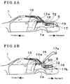
- Fig. 2A is a side view of the vehicle equipped with the roof opening and closing apparatus in a case where a roof of the vehicle is in a deployed state;
- Fig. 2B is a side view of the vehicle equipped with the roof opening and closing apparatus in a case where a storage compartment is opened;
- Fig. 3A is a side view of the vehicle equipped with the roof opening and closing apparatus in a case where the roof is in a process of being stored from the deployed state;
- Fig. 3B is a side view of the vehicle equipped with the roof opening and closing apparatus in a case where the roof is completely stored;
- Fig. 4 is an enlarged view of a portion IV shown in Fig. 3A ;
- Fig. 6 is an enlarged view of a portion VI shown in Fig. 3B .
- a roof opening and closing apparatus for a vehicle includes a cover member opening and closing mechanism 5, a roof opening and closing mechanism 3, a panel moving mechanism 70, and the like.
- two cover member opening and closing mechanisms 5, two roof opening and closing mechanisms 3, and two panel moving mechanisms 70 are symmetrically provided at right and left sides of a vehicle 1 (i.e., both sides in a width direction of the vehicle 1).
- the cover member opening and closing mechanism 5, the roof opening and closing mechanism 3, and the panel moving mechanism 70 provided at one of the right and left sides of the vehicle 1 will be explained as an example.
- the vehicle 1 includes a movable roof 10, herein referred to as a roof 10.
- the roof 10 of the vehicle 1 is changeable between a deployed state and a stored state.
- Fig. 2A is a side view of the vehicle 1 illustrating the cover member 16 in a closed state.
- Fig. 2B is a side view of the vehicle 1 illustrating the cover member 16 of which rear end is lifted up so that luggage can be taken in or out of the storage compartment 19.
- a lock device 17 is attached to a rear end portion of the cover member 16 for causing the cover member 16 to engage with a vehicle body 1 a.
- the cover member opening and closing mechanism 5 is provided within the storage compartment 19, being supported by the vehicle body 1 a.
- the cover member opening and closing mechanism 5 includes a rear side opening and closing mechanical unit 50 for opening and closing the cover member 16 in such a way that a rear portion of the cover member 16 is moved to a greater extent in a substantially vertical direction of the vehicle than a front portion of the cover member 16.
- the lock device 17 includes a lock main body 17a attached to the cover member 16 and a lock catcher 17b attached to the vehicle body 1a. The engagement between the lock main body 17a and the lock catcher 17b is released and thereafter the cover member 16 is opened and closed by means of the rear side opening and closing mechanical unit 50.
- the roof opening and closing mechanism 3 moves the front portion 11 and the intermediate portion 12, and a rear roof opening and closing apparatus 4 for moving the rear portion 13.
- the cover member opening and closing mechanism 5 includes a front side opening and closing mechanical unit 60 for lifting up the front portion of the cover member 16 so as to open the cover member 16 when the roof 10 is moved.
- the panel moving mechanism 70 is attached to the intermediate support unit 51.
- the panel moving mechanism 70 includes a drive unit 73, a panel movement mechanical unit 71, and a panel member 72.
- the drive unit 73 which is fixed to the intermediate support unit 51, includes an electric motor serving as a driving source for moving the panel member 72.
- the panel movement mechanical unit 71 includes a parallel linkage constituted by two link arms 71 a and 71 b. One end of the link arm 71 a is rotatably supported by the drive unit 73 about a pivot while the other end of the link arm 71 a extends towards the cover member 16.
- one end of the link arm 71 b is rotatably supported by the drive unit 73 about a pivot while the other end of the like arm 71 b extends towards the cover member 16.
- Both other ends of the link arms 71 a and 71 b are rotatably connected to the panel member 72 about the respective pivots so that the panel movement mechanical unit 71 supports the panel member 72 to be movable.
- Fig. 5 is a diagram of the vehicle 1 when viewed from a direction V in Fig. 3B .
- the panel member 72 covers a portion of the vehicle body 1 a that is positioned in the vicinity of a lower end of the pillar portion 13a provided at the rear window 15 when the roof 10 is in the deployed state.
- the panel member 72 and a center panel 91 that is positioned between the panel members 72 provided at both left and right sides of the vehicle 1 in the width direction assures the improved appearance of the vehicle 1 by covering an upper portion of the storage compartment 19.
- the center panel 91 vertically extends when the roof 10 moves and the panel member 72 moves upward together with the cover member 16 so that the panel member 72 is operated not to interfere with the movement of the roof 10.
- the panel member 72 is positioned as illustrated by a chain double-dashed line in Fig. 5 .
- the link arm 71 a rotates by following a locus "a” while the link arm 71 b rotates by following a locus "b". That is, the parallel linkage by the link arms 71 a and 71 b, which rotate while having a predetermined distance therebetween, assures each position of the panel member 72 while the panel member 72 is moving.
- the panel member 72 moves from the position illustrated by the solid line to the position illustrated by the chain double-dashed line in Fig. 5 when the roof 10 is in a process of being deployed.
- the panel member 72 moves from the position illustrated by the chain double-dashed line to the position illustrated by the solid line when the roof 10 is in a process of being stored in the storage compartment 19 as illustrated in Fig. 3A .
- the roof 10 having the aforementioned structure is shifted between the deployed state and the stored state based on a control program included in a roof control unit provided at the vehicle 1 so that the related members and portions are controlled and interlocked.
- the panel member 72 in addition to the panel movement mechanical unit 71 and the drive unit 73 attached to the intermediate support unit 51 of the cover member opening and closing mechanism 5 and the cover member 16, is lifted up to a position where the panel member 72 is prevented from interfering with the roof 10.
- a size and a shape of the panel member 72 in view of a flat face are not likely to be restricted by a space (i.e., a limited space) within the storage compartment 19.
- flexibility of design in view of ensuring the improved appearance of the vehicle 1 of which the vehicle 10 is in the stored state is improved, thereby contributing to a design enhancement of the vehicle's appearance.
Abstract
Description
- The present invention relates to a roof opening and closing apparatus for a vehicle. More particularly, the present invention pertains to a roof opening and closing apparatus for a vehicle including a panel moving mechanism.
- A known vehicle is equipped with a roof that is changeable between a deployed state where a vehicle interior space is covered and a stored state where a luggage room provided at a rear of the vehicle is used as a storage compartment of the roof.
- The aforementioned vehicle includes pillar portions that are provided at both left and right sides of a rear window of the roof in a width direction of the vehicle and that extend in a vertical direction of the vehicle. In a case where the roof is in the stored state, a clearance originally covered by a lower end of the pillar portion and penetrating through the luggage room is covered by a panel member. That is, in a case where the roof is in the stored state, an improved appearance of the vehicle is ensured by the panel member. In order to return the roof from the stored state to the deployed state, a panel moving mechanism of a roof opening and closing apparatus for a vehicle is provided to store the panel member in the luggage room.
- A mechanical unit of the aforementioned panel moving mechanism is attached to a vehicle body within the luggage room. When the roof is deployed or stored in the luggage room, the panel member is positioned within the luggage room in such a way that the panel member is prevented from interfering with the roof. After completion of the storage of the roof in the luggage room, the panel member is moved to a position where the pillar portion is provided when the roof is in the deployed state by means of an operation of the panel moving mechanism. Such panel moving mechanism is disclosed in
DE10132547B4 . - However, according to the panel moving mechanism disclosed in
DE1013247B4 , an area and a shape of the panel member is restricted so as to prevent the interference between the panel member and the roof within a limited space of the luggage room. As a result, an effect for ensuring the improved appearance of the vehicle may not be adequately achieved. - A need thus exists for a roof opening and closing apparatus for a vehicle which includes a panel moving mechanism having a flexibility of area and shape of a panel member and an excellent design.
- According to an aspect of the present invention, a roof opening and closing apparatus for a vehicle includes a cover member opening and closing mechanism adapted to be supported by a vehicle body and moving a cover member adapted to cover a roof when the roof is stored within a storage compartment provided at the vehicle body. The cover member opening and closing mechanism includes a front side opening and closing mechanical unit adapted to be connected to the vehicle body and moving a front portion of the cover member to a greater extent in a vertical direction of the vehicle than a rear portion of the cover member, a rear side opening and closing mechanical unit adapted to support the cover member and moving the rear portion of the cover member to a greater extent in the vertical direction of the vehicle than the front portion of the cover member, and an intermediate support unit connecting the front side opening and closing mechanical unit and the rear side opening and closing mechanical unit to each other. The roof opening and closing apparatus further includes a panel moving mechanism including a panel member and a panel movement mechanical unit, the panel member covering a portion of the vehicle body in a case where the roof is in a stored state where the roof is stored in the storage compartment, the portion of the vehicle body being positioned at a lower end of a rear corner portion of the roof when the roof is in a developed state where the roof covers a vehicle interior space of the vehicle, and the panel movement mechanical unit supported by the intermediate support unit and supporting the panel member to be moved to the storage compartment in a case where the roof is in the deployed state.
- According to the aforementioned invention, the panel moving mechanism is attached to the intermediate support unit of the cover member opening and closing mechanism . Thus, while the roof is moving, the panel member is lifted up together with the cover member to a position where the panel member is prevented from interfering with the roof. Accordingly, the panel member is unlikely to be restricted by a space within the storage compartment. An area and a shape of the panel member are flexibly determined accordingly. Thus, flexibility of design in view of ensuring the improved appearance of the vehicle of which the roof is in the stored state is improved, thereby contributing to a design enhancement of the vehicle's appearance.
- The roof opening and closing apparatus further includes an engagement mechanism adapted to be connected to the vehicle body within the storage compartment and locking the roof in the storage state, wherein the panel member is arranged above the engagement mechanism in the storage state of the roof.
- In a case where the roof is in the deployed state, the storage compartment is used for accommodating luggage. The engagement mechanism is provided within the storage compartment for locking the roof. The panel member is arranged at an upper portion of the engagement mechanism within the storage compartment to thereby prevent the interference between luggage and the engagement mechanism when luggage is taken in or out of the storage compartment and to ensure the appearance of the vehicle.
- The panel movement mechanical unit includes a parallel linkage constituted by first and second link arms rotating while having a predetermined distance therebetween.
- According to the aforementioned invention, the parallel linkage ensures each position of the panel member while the panel member is moving. As a result, the panel member is appropriately and precisely arranged at a predetermined position where the improved vehicle appearance is assured. In addition, the panel member is prevented from making contact with a portion of the vehicle body caused by a vibration during a driving of the vehicle, and the like.
- The panel member and the cover member are moved to be positioned at an upper side of the storage compartment when the roof is changed between the deployed state and the stored state.
- The roof opening and closing apparatus further includes a roof opening and closing mechanism adapted to support the roof to be movable, wherein the roof includes a front portion and a rear portion that is arranged at a rear of the vehicle relative to the front portion, the rear portion including a rear window and the rear corner portions provided at both right and left sides of the rear window in a width direction of the vehicle.
- The panel member is arranged at each side of the vehicle in the width direction, and a center panel adapted to be supported by the vehicle body is arranged between the panel members.
- The foregoing and additional features and characteristics of the present invention will become more apparent from the following detailed description considered with the reference to the accompanying drawings, wherein:
-
Fig. 1 is a perspective view of a vehicle equipped with a roof opening and closing apparatus for a vehicle when viewed from a rear upper side of the vehicle according to an embodiment of the present invention; -
Fig. 2A is a side view of the vehicle equipped with the roof opening and closing apparatus in a case where a roof of the vehicle is in a deployed state; -
Fig. 2B is a side view of the vehicle equipped with the roof opening and closing apparatus in a case where a storage compartment is opened; -
Fig. 3A is a side view of the vehicle equipped with the roof opening and closing apparatus in a case where the roof is in a process of being stored from the deployed state; -
Fig. 3B is a side view of the vehicle equipped with the roof opening and closing apparatus in a case where the roof is completely stored; -
Fig. 4 is an enlarged view of a portion IV shown inFig. 3A ; -
Fig. 5 is a view on arrow V shown inFig. 3B ; and -
Fig. 6 is an enlarged view of a portion VI shown inFig. 3B . - An embodiment of the present invention will be explained with reference to the attached drawings.
- A roof opening and closing apparatus for a vehicle according to the embodiment includes a cover member opening and
closing mechanism 5, a roof opening andclosing mechanism 3, apanel moving mechanism 70, and the like. In the embodiment, two cover member opening andclosing mechanisms 5, two roof opening andclosing mechanisms 3, and twopanel moving mechanisms 70 are symmetrically provided at right and left sides of a vehicle 1 (i.e., both sides in a width direction of the vehicle 1). In the following, unless otherwise specified, the cover member opening andclosing mechanism 5, the roof opening andclosing mechanism 3, and thepanel moving mechanism 70 provided at one of the right and left sides of thevehicle 1 will be explained as an example. As illustrated inFig. 1 , thevehicle 1 includes amovable roof 10, herein referred to as aroof 10. Theroof 10 of thevehicle 1 is changeable between a deployed state and a stored state. - The
roof 10 illustrated inFig. 1 is in the deployed state. Theroof 10 is constituted by afront portion 11, anintermediate portion 12, and arear portion 13 arranged in this order from a front to a rear of thevehicle 1 so as to cover a vehicleinterior space 18. Arear window 15 and pillar portions 13a (rear corner portions) are provided at therear portion 13. The pillar portions 13a are provided at both left and right sides of therear window 15 in the width direction so as to extend in a vertical direction of thevehicle 1. - Further, as illustrated in
Fig. 1 , thevehicle 1 includes astorage compartment 19 at a rear, which is generally used as a luggage room. Acover member 16 that can be opened and closed is attached to thestorage compartment 19. -
Fig. 2A is a side view of thevehicle 1 illustrating thecover member 16 in a closed state.Fig. 2B is a side view of thevehicle 1 illustrating thecover member 16 of which rear end is lifted up so that luggage can be taken in or out of thestorage compartment 19. Alock device 17 is attached to a rear end portion of thecover member 16 for causing thecover member 16 to engage with a vehicle body 1 a. - As illustrated in
Figs. 2A and 2B , the cover member opening andclosing mechanism 5 is provided within thestorage compartment 19, being supported by the vehicle body 1 a. The cover member opening andclosing mechanism 5 includes a rear side opening and closingmechanical unit 50 for opening and closing thecover member 16 in such a way that a rear portion of thecover member 16 is moved to a greater extent in a substantially vertical direction of the vehicle than a front portion of thecover member 16. Thelock device 17 includes a lock main body 17a attached to thecover member 16 and alock catcher 17b attached to the vehicle body 1a. The engagement between the lock main body 17a and thelock catcher 17b is released and thereafter thecover member 16 is opened and closed by means of the rear side opening and closingmechanical unit 50. - The roof opening and
closing mechanism 3 moves thefront portion 11 and theintermediate portion 12, and a rear roof opening andclosing apparatus 4 for moving therear portion 13. As illustrated inFig. 3A , the cover member opening andclosing mechanism 5 includes a front side opening and closingmechanical unit 60 for lifting up the front portion of thecover member 16 so as to open thecover member 16 when theroof 10 is moved. - As illustrated in
Fig. 4 , the cover member opening andclosing mechanism 5 includes a covermember drive unit 52 attached to the vehicle body 1 a within thestorage compartment 19. A lower end of the front side opening and closingmechanical unit 60 including multiple link members is connected to the covermember drive unit 52. An upper end of the front side opening and closingmechanical unit 60 is connected to anintermediate support unit 51, which is connected to a lower end of the rear side opening and closingmechanical unit 50. An upper end of the rear side opening and closingmechanical unit 50 is connected to abracket 16a, which is fixed to a front edge of thecover member 16, so as to support thecover member 16. - Further, as illustrated in
Fig. 4 , thepanel moving mechanism 70 is attached to theintermediate support unit 51. Thepanel moving mechanism 70 includes adrive unit 73, a panel movementmechanical unit 71, and apanel member 72. Thedrive unit 73, which is fixed to theintermediate support unit 51, includes an electric motor serving as a driving source for moving thepanel member 72. The panel movementmechanical unit 71 includes a parallel linkage constituted by twolink arms link arm 71 a is rotatably supported by thedrive unit 73 about a pivot while the other end of thelink arm 71 a extends towards thecover member 16. In the same way, one end of thelink arm 71 b is rotatably supported by thedrive unit 73 about a pivot while the other end of thelike arm 71 b extends towards thecover member 16. Both other ends of thelink arms panel member 72 about the respective pivots so that the panel movementmechanical unit 71 supports thepanel member 72 to be movable. -
Fig. 5 is a diagram of thevehicle 1 when viewed from a direction V inFig. 3B . In a case where theroof 10 is in the stored state, thepanel member 72 covers a portion of the vehicle body 1 a that is positioned in the vicinity of a lower end of the pillar portion 13a provided at therear window 15 when theroof 10 is in the deployed state. Thepanel member 72 and acenter panel 91 that is positioned between thepanel members 72 provided at both left and right sides of thevehicle 1 in the width direction assures the improved appearance of thevehicle 1 by covering an upper portion of thestorage compartment 19. As illustrated inFig. 3A , thecenter panel 91 vertically extends when theroof 10 moves and thepanel member 72 moves upward together with thecover member 16 so that thepanel member 72 is operated not to interfere with the movement of theroof 10. - In a case where the
roof 10 is in the deployed state as illustrated inFig. 2A or 2B , thepanel member 72 is positioned as illustrated by a chain double-dashed line inFig. 5 . When thepanel member 72 moves between the position illustrated by a solid line and the position illustrated by the chain double-dashed line inFig. 5 , thelink arm 71 a rotates by following a locus "a" while thelink arm 71 b rotates by following a locus "b". That is, the parallel linkage by thelink arms panel member 72 while thepanel member 72 is moving. - The
panel member 72 moves from the position illustrated by the solid line to the position illustrated by the chain double-dashed line inFig. 5 when theroof 10 is in a process of being deployed. Thepanel member 72 moves from the position illustrated by the chain double-dashed line to the position illustrated by the solid line when theroof 10 is in a process of being stored in thestorage compartment 19 as illustrated inFig. 3A . - As illustrated in
Fig. 6 , a striker 3a is attached to the roof opening andclosing mechanism 3 accommodated in thestorage compartment 19. Anengagement mechanism 9 including a hook 9a engageable with the striker 3a is provided within thestorage compartment 19. When thepanel member 72 is arranged in the position as illustrated by the chain double-dashed line inFig. 5 , thepanel member 72 is configured to cover an upper portion of the engagement mechanism 9 (i.e., a portion of the vehicle body 1 a). Accordingly, in a case where the rear portion of thecover member 16 is lifted up so that luggage can be taken in or out of thestorage compartment 19, the luggage is prevented from interfering with theengagement mechanism 9. In addition, covering theengagement mechanism 9 improves the appearance of the vehicle. - The
roof 10 having the aforementioned structure is shifted between the deployed state and the stored state based on a control program included in a roof control unit provided at thevehicle 1 so that the related members and portions are controlled and interlocked. - According to the aforementioned embodiment, the
panel member 72, in addition to the panel movementmechanical unit 71 and thedrive unit 73 attached to theintermediate support unit 51 of the cover member opening andclosing mechanism 5 and thecover member 16, is lifted up to a position where thepanel member 72 is prevented from interfering with theroof 10. Thus, a size and a shape of thepanel member 72 in view of a flat face are not likely to be restricted by a space (i.e., a limited space) within thestorage compartment 19. Thus, flexibility of design in view of ensuring the improved appearance of thevehicle 1 of which thevehicle 10 is in the stored state is improved, thereby contributing to a design enhancement of the vehicle's appearance.
Claims (6)
- A roof opening and closing apparatus for a vehicle, comprising:a cover member opening and closing mechanism adapted to be supported by a vehicle body and moving a cover member adapted to cover a roof when the roof is stored within a storage compartment provided at the vehicle body;the cover member opening and closing mechanism including a front side opening and closing mechanical unit adapted to be connected to the vehicle body and moving a front portion of the cover member to a greater extent in a vertical direction of the vehicle than a rear portion of the cover member, a rear side opening and closing mechanical unit adapted to support the cover member and moving the rear portion of the cover member to a greater extent in the vertical direction of the vehicle than the front portion of the cover member, and an intermediate support unit connecting the front side opening and closing mechanical unit and the rear side opening and closing mechanical unit to each other;a panel moving mechanism including a panel member and a panel movement mechanical unit;the panel member covering a portion of the vehicle body in a case where the roof is in a stored state where the roof is stored in the storage compartment, the portion of the vehicle body being positioned at a lower end of a rear corner portion of the roof when the roof is in a developed state where the roof covers a vehicle interior space of the vehicle; andthe panel movement mechanical unit supported by the intermediate support unit and supporting the panel member to be moved to the storage compartment in a case where the roof is in the deployed state.
- The roof opening and closing apparatus according to claim 1, further comprising an engagement mechanical unit adapted to be connected to the vehicle body within the storage compartment and locking the roof in the storage state, wherein the panel member is arranged above the engagement mechanical unit in the storage state of the roof.
- The roof opening and closing apparatus according to one of claims 1 and 2, wherein the panel movement mechanical unit includes a parallel linkage constituted by first and second link arms rotating while having a predetermined distance therebetween.
- The roof opening and closing apparatus according to any one of claims 1 through 3, wherein the panel member and the cover member are moved to be positioned at an upper side of the storage compartment when the roof is changed between the deployed state and the stored state.
- The roof opening and closing apparatus according to any one of claims 1 through 4, further comprising a roof opening and closing mechanism adapted to support the roof to be movable, wherein the roof includes a front portion and a rear portion that is arranged at a rear of the vehicle relative to the front portion, the rear portion including a rear window and the rear corner portions provided at both right and left sides of the rear window in a width direction of the vehicle.
- The roof opening and closing apparatus according to any one of claims 1 through 5, wherein the panel member is arranged at each side of the vehicle in the width direction, and a center panel adapted to be supported by the vehicle body is arranged between the panel members.
Applications Claiming Priority (1)
| Application Number | Priority Date | Filing Date | Title |
|---|---|---|---|
| JP2008193115A JP5245610B2 (en) | 2008-07-28 | 2008-07-28 | Panel moving device |
Publications (2)
| Publication Number | Publication Date |
|---|---|
| EP2149467A1 true EP2149467A1 (en) | 2010-02-03 |
| EP2149467B1 EP2149467B1 (en) | 2012-09-26 |
Family
ID=41262032
Family Applications (1)
| Application Number | Title | Priority Date | Filing Date |
|---|---|---|---|
| EP09009633A Not-in-force EP2149467B1 (en) | 2008-07-28 | 2009-07-24 | Roof opening and closing apparatus for vehicle |
Country Status (3)
| Country | Link |
|---|---|
| US (1) | US8042857B2 (en) |
| EP (1) | EP2149467B1 (en) |
| JP (1) | JP5245610B2 (en) |
Families Citing this family (7)
| Publication number | Priority date | Publication date | Assignee | Title |
|---|---|---|---|---|
| JP5245610B2 (en) * | 2008-07-28 | 2013-07-24 | アイシン精機株式会社 | Panel moving device |
| EP2196343A1 (en) * | 2008-12-12 | 2010-06-16 | Mazda Motor Corporation | Roof opening structure for a vehicle |
| DE102009014968A1 (en) * | 2009-03-18 | 2010-09-23 | Dr. Ing. H.C. F. Porsche Aktiengesellschaft | Hood for a convertible and convertible with a hood |
| JP6160505B2 (en) * | 2014-02-20 | 2017-07-12 | マツダ株式会社 | Fiber reinforced plastic lid member |
| JP6160506B2 (en) * | 2014-02-20 | 2017-07-12 | マツダ株式会社 | Vehicle structure |
| US9561711B2 (en) * | 2014-03-19 | 2017-02-07 | Ferrari S.P.A. | Convertible car with a rigid sunroof and a front engine and corresponding control method |
| JP6315012B2 (en) * | 2016-03-18 | 2018-04-25 | マツダ株式会社 | Rear body structure of a car with retractable roof |
Citations (4)
| Publication number | Priority date | Publication date | Assignee | Title |
|---|---|---|---|---|
| DE1013247B (en) | 1953-02-09 | 1957-08-08 | Ewald Wiemann Maschf | Ball joint-like cap connection |
| DE10052001A1 (en) * | 2000-10-20 | 2002-05-08 | Karmann Gmbh W | Convertible has hatchback, which can be raised at back to allow luggage to be put in or at front to allow roof to be moved under it, on lever system comprising section attached to hatchback and section attached to auxiliary frame component |
| DE10132547B4 (en) | 2001-07-09 | 2005-03-24 | Webasto Ag | Cover plate for the hood frame of a convertible |
| WO2006131100A1 (en) * | 2005-06-08 | 2006-12-14 | Wilhelm Karmann Gmbh | Convertible with a roof which can be stored below a covering |
Family Cites Families (23)
| Publication number | Priority date | Publication date | Assignee | Title |
|---|---|---|---|---|
| FR2777240B1 (en) * | 1998-04-09 | 2000-06-09 | France Design | REAR TRUNK FOR DISCOVERABLE VEHICLE WITH FOLDABLE ROOF, COMPRISING A REAR TRUNK AND A REAR BEACH |
| JP2000103288A (en) | 1998-09-29 | 2000-04-11 | Toyota Motor Corp | Housing structure of package tray |
| JP4292354B2 (en) * | 1999-10-19 | 2009-07-08 | アイシン精機株式会社 | Package tray for vehicles |
| JP2002002301A (en) * | 2000-06-19 | 2002-01-09 | Takada Kogyo Kk | Mechanism for preventing catching-in |
| DE10039683B4 (en) * | 2000-08-14 | 2005-02-24 | Wilhelm Karmann Gmbh | Convertible car |
| EP1199202B1 (en) * | 2000-10-20 | 2007-02-14 | Wilhelm Karmann GmbH | Convertible vehicle with a roof storable beneath a cover element on the rear part of the vehicle |
| DE10134370B4 (en) * | 2001-07-14 | 2006-01-05 | Daimlerchrysler Ag | Covering device for a convertible top compartment |
| DE20208001U1 (en) * | 2002-05-23 | 2003-10-02 | Karmann Gmbh W | Cabriolet vehicle with a roof that can be stored under a cover part |
| FR2842467B1 (en) * | 2002-07-19 | 2008-07-18 | France Design | REAR RANGE SYSTEM FOR DISABLED VEHICLE WITH FOLDING RIGID ROOF |
| DE10234350C5 (en) * | 2002-07-28 | 2012-09-27 | Webasto Ag | Covering device for a removable roof of a convertible and convertible with such a cover device |
| DE10234351B4 (en) * | 2002-07-28 | 2012-10-04 | Webasto Ag | Convertible with removable folding roof |
| DE10251409A1 (en) * | 2002-11-05 | 2004-06-09 | Wilhelm Karmann Gmbh | Cabriolet vehicle with retractable top |
| FR2851511A1 (en) * | 2003-02-21 | 2004-08-27 | Renault Sa | Retractable roof for vehicle, has rear covering structure including closing shutters that are apt to be rotated between deployed and lined position by rotating mechanism operated by energy motor |
| FR2851510A1 (en) * | 2003-02-21 | 2004-08-27 | Renault Sa | Retractable roof for vehicle, has panel to be moved by guiding device to closed position in passenger zone of vehicle and retractable position in rear zone of vehicle |
| FR2853868B1 (en) * | 2003-04-15 | 2005-06-24 | France Design | RETRACTABLE REAR RANGE SYSTEM FOR A DISABLED VEHICLE WITH A FOLDING ROOF |
| FR2872479B1 (en) * | 2004-07-02 | 2006-09-08 | France Design Sa | DEVICE FOR PROTECTING OBJECTS ARRANGED IN THE REAR CHEST OF A MOTOR VEHICLE WITH A RETRACTABLE ROOF |
| DE102004041539A1 (en) * | 2004-08-27 | 2006-03-02 | Wilhelm Karmann Gmbh | Cabriolet vehicle with a roof mounted on lateral roof bars |
| WO2006084070A2 (en) * | 2005-02-03 | 2006-08-10 | Cts Fahrzeug Dachsysteme Gmbh | Retractable vehicle top and combined package shelf and tonneau cover |
| DE102006005001B4 (en) * | 2006-02-01 | 2008-06-05 | Magna Car Top Systems Gmbh | Convertible car |
| DE102006007362A1 (en) * | 2006-02-17 | 2007-08-23 | Wilhelm Karmann Gmbh | Motor vehicle with a movable, overlapped by a roof cover roof area |
| JP5157396B2 (en) * | 2007-11-30 | 2013-03-06 | アイシン精機株式会社 | Roof storage device |
| JP5245610B2 (en) * | 2008-07-28 | 2013-07-24 | アイシン精機株式会社 | Panel moving device |
| US7819459B2 (en) * | 2009-02-11 | 2010-10-26 | Valmet Automotive Oy | Convertible vehicle |
-
2008
- 2008-07-28 JP JP2008193115A patent/JP5245610B2/en active Active
-
2009
- 2009-07-23 US US12/508,147 patent/US8042857B2/en not_active Expired - Fee Related
- 2009-07-24 EP EP09009633A patent/EP2149467B1/en not_active Not-in-force
Patent Citations (4)
| Publication number | Priority date | Publication date | Assignee | Title |
|---|---|---|---|---|
| DE1013247B (en) | 1953-02-09 | 1957-08-08 | Ewald Wiemann Maschf | Ball joint-like cap connection |
| DE10052001A1 (en) * | 2000-10-20 | 2002-05-08 | Karmann Gmbh W | Convertible has hatchback, which can be raised at back to allow luggage to be put in or at front to allow roof to be moved under it, on lever system comprising section attached to hatchback and section attached to auxiliary frame component |
| DE10132547B4 (en) | 2001-07-09 | 2005-03-24 | Webasto Ag | Cover plate for the hood frame of a convertible |
| WO2006131100A1 (en) * | 2005-06-08 | 2006-12-14 | Wilhelm Karmann Gmbh | Convertible with a roof which can be stored below a covering |
Also Published As
| Publication number | Publication date |
|---|---|
| JP5245610B2 (en) | 2013-07-24 |
| US8042857B2 (en) | 2011-10-25 |
| EP2149467B1 (en) | 2012-09-26 |
| US20100019531A1 (en) | 2010-01-28 |
| JP2010030377A (en) | 2010-02-12 |
Similar Documents
| Publication | Publication Date | Title |
|---|---|---|
| EP2149467B1 (en) | Roof opening and closing apparatus for vehicle | |
| JP4293938B2 (en) | Split lid mechanism and center console box | |
| EP1842710B1 (en) | Retractable roof and vehicle therewith | |
| JP2003025856A (en) | Storing structure of convertible hardtop | |
| KR100963699B1 (en) | Pivoting convertible roof for a motor vehicle | |
| EP2065240B1 (en) | Vehicle roof opening/closing apparatus | |
| EP1334856B1 (en) | A mechanism for opening a gull-wing side door of a motor vehicle | |
| EP4039926A1 (en) | Door handle structure of a vehicle | |
| CN110239319B (en) | Ceiling structure of automobile | |
| KR20100064142A (en) | Hood lifter of vehicles | |
| JP5577725B2 (en) | Vehicle tonneau cover device | |
| JP4890861B2 (en) | Lid opening / closing device | |
| JP6311536B2 (en) | Rear body structure of the vehicle | |
| JP4203196B2 (en) | Interior parts for vehicles | |
| JP2002264657A (en) | Retractable roof | |
| US6962391B2 (en) | Open roof structure for vehicle | |
| JP2003246221A (en) | Roof opening/closing unit for vehicle | |
| EP1718834A1 (en) | Opening leaf for vehicle | |
| JP2003165339A (en) | Roof automatic opening/closing device | |
| JP2011161978A (en) | Tonneau cover device for vehicle | |
| JPS62120218A (en) | Structure of roof for car | |
| JP6252180B2 (en) | Vehicle door structure | |
| JPS62120222A (en) | Device for operating open roof for car | |
| JPS62120219A (en) | Structure of roof for car | |
| JPH06466B2 (en) | Automotive open roof structure |
Legal Events
| Date | Code | Title | Description |
|---|---|---|---|
| PUAI | Public reference made under article 153(3) epc to a published international application that has entered the european phase |
Free format text: ORIGINAL CODE: 0009012 |
|
| AK | Designated contracting states |
Kind code of ref document: A1 Designated state(s): AT BE BG CH CY CZ DE DK EE ES FI FR GB GR HR HU IE IS IT LI LT LU LV MC MK MT NL NO PL PT RO SE SI SK SM TR |
|
| AX | Request for extension of the european patent |
Extension state: AL BA RS |
|
| 17P | Request for examination filed |
Effective date: 20100119 |
|
| GRAP | Despatch of communication of intention to grant a patent |
Free format text: ORIGINAL CODE: EPIDOSNIGR1 |
|
| GRAS | Grant fee paid |
Free format text: ORIGINAL CODE: EPIDOSNIGR3 |
|
| GRAA | (expected) grant |
Free format text: ORIGINAL CODE: 0009210 |
|
| AK | Designated contracting states |
Kind code of ref document: B1 Designated state(s): AT BE BG CH CY CZ DE DK EE ES FI FR GB GR HR HU IE IS IT LI LT LU LV MC MK MT NL NO PL PT RO SE SI SK SM TR |
|
| REG | Reference to a national code |
Ref country code: GB Ref legal event code: FG4D |
|
| REG | Reference to a national code |
Ref country code: CH Ref legal event code: EP |
|
| REG | Reference to a national code |
Ref country code: AT Ref legal event code: REF Ref document number: 576866 Country of ref document: AT Kind code of ref document: T Effective date: 20121015 |
|
| REG | Reference to a national code |
Ref country code: IE Ref legal event code: FG4D |
|
| REG | Reference to a national code |
Ref country code: DE Ref legal event code: R096 Ref document number: 602009009944 Country of ref document: DE Effective date: 20121122 |
|
| PG25 | Lapsed in a contracting state [announced via postgrant information from national office to epo] |
Ref country code: NO Free format text: LAPSE BECAUSE OF FAILURE TO SUBMIT A TRANSLATION OF THE DESCRIPTION OR TO PAY THE FEE WITHIN THE PRESCRIBED TIME-LIMIT Effective date: 20121226 Ref country code: LT Free format text: LAPSE BECAUSE OF FAILURE TO SUBMIT A TRANSLATION OF THE DESCRIPTION OR TO PAY THE FEE WITHIN THE PRESCRIBED TIME-LIMIT Effective date: 20120926 Ref country code: FI Free format text: LAPSE BECAUSE OF FAILURE TO SUBMIT A TRANSLATION OF THE DESCRIPTION OR TO PAY THE FEE WITHIN THE PRESCRIBED TIME-LIMIT Effective date: 20120926 Ref country code: HR Free format text: LAPSE BECAUSE OF FAILURE TO SUBMIT A TRANSLATION OF THE DESCRIPTION OR TO PAY THE FEE WITHIN THE PRESCRIBED TIME-LIMIT Effective date: 20120926 |
|
| REG | Reference to a national code |
Ref country code: AT Ref legal event code: MK05 Ref document number: 576866 Country of ref document: AT Kind code of ref document: T Effective date: 20120926 |
|
| REG | Reference to a national code |
Ref country code: LT Ref legal event code: MG4D Effective date: 20120926 |
|
| REG | Reference to a national code |
Ref country code: NL Ref legal event code: VDEP Effective date: 20120926 |
|
| PG25 | Lapsed in a contracting state [announced via postgrant information from national office to epo] |
Ref country code: LV Free format text: LAPSE BECAUSE OF FAILURE TO SUBMIT A TRANSLATION OF THE DESCRIPTION OR TO PAY THE FEE WITHIN THE PRESCRIBED TIME-LIMIT Effective date: 20120926 Ref country code: GR Free format text: LAPSE BECAUSE OF FAILURE TO SUBMIT A TRANSLATION OF THE DESCRIPTION OR TO PAY THE FEE WITHIN THE PRESCRIBED TIME-LIMIT Effective date: 20121227 Ref country code: SI Free format text: LAPSE BECAUSE OF FAILURE TO SUBMIT A TRANSLATION OF THE DESCRIPTION OR TO PAY THE FEE WITHIN THE PRESCRIBED TIME-LIMIT Effective date: 20120926 Ref country code: SE Free format text: LAPSE BECAUSE OF FAILURE TO SUBMIT A TRANSLATION OF THE DESCRIPTION OR TO PAY THE FEE WITHIN THE PRESCRIBED TIME-LIMIT Effective date: 20120926 |
|
| PG25 | Lapsed in a contracting state [announced via postgrant information from national office to epo] |
Ref country code: ES Free format text: LAPSE BECAUSE OF FAILURE TO SUBMIT A TRANSLATION OF THE DESCRIPTION OR TO PAY THE FEE WITHIN THE PRESCRIBED TIME-LIMIT Effective date: 20130106 Ref country code: EE Free format text: LAPSE BECAUSE OF FAILURE TO SUBMIT A TRANSLATION OF THE DESCRIPTION OR TO PAY THE FEE WITHIN THE PRESCRIBED TIME-LIMIT Effective date: 20120926 Ref country code: BE Free format text: LAPSE BECAUSE OF FAILURE TO SUBMIT A TRANSLATION OF THE DESCRIPTION OR TO PAY THE FEE WITHIN THE PRESCRIBED TIME-LIMIT Effective date: 20120926 Ref country code: RO Free format text: LAPSE BECAUSE OF FAILURE TO SUBMIT A TRANSLATION OF THE DESCRIPTION OR TO PAY THE FEE WITHIN THE PRESCRIBED TIME-LIMIT Effective date: 20120926 Ref country code: CZ Free format text: LAPSE BECAUSE OF FAILURE TO SUBMIT A TRANSLATION OF THE DESCRIPTION OR TO PAY THE FEE WITHIN THE PRESCRIBED TIME-LIMIT Effective date: 20120926 Ref country code: IS Free format text: LAPSE BECAUSE OF FAILURE TO SUBMIT A TRANSLATION OF THE DESCRIPTION OR TO PAY THE FEE WITHIN THE PRESCRIBED TIME-LIMIT Effective date: 20130126 Ref country code: NL Free format text: LAPSE BECAUSE OF FAILURE TO SUBMIT A TRANSLATION OF THE DESCRIPTION OR TO PAY THE FEE WITHIN THE PRESCRIBED TIME-LIMIT Effective date: 20120926 |
|
| PG25 | Lapsed in a contracting state [announced via postgrant information from national office to epo] |
Ref country code: PL Free format text: LAPSE BECAUSE OF FAILURE TO SUBMIT A TRANSLATION OF THE DESCRIPTION OR TO PAY THE FEE WITHIN THE PRESCRIBED TIME-LIMIT Effective date: 20120926 Ref country code: PT Free format text: LAPSE BECAUSE OF FAILURE TO SUBMIT A TRANSLATION OF THE DESCRIPTION OR TO PAY THE FEE WITHIN THE PRESCRIBED TIME-LIMIT Effective date: 20130128 Ref country code: SK Free format text: LAPSE BECAUSE OF FAILURE TO SUBMIT A TRANSLATION OF THE DESCRIPTION OR TO PAY THE FEE WITHIN THE PRESCRIBED TIME-LIMIT Effective date: 20120926 Ref country code: CY Free format text: LAPSE BECAUSE OF FAILURE TO SUBMIT A TRANSLATION OF THE DESCRIPTION OR TO PAY THE FEE WITHIN THE PRESCRIBED TIME-LIMIT Effective date: 20120926 |
|
| PG25 | Lapsed in a contracting state [announced via postgrant information from national office to epo] |
Ref country code: AT Free format text: LAPSE BECAUSE OF FAILURE TO SUBMIT A TRANSLATION OF THE DESCRIPTION OR TO PAY THE FEE WITHIN THE PRESCRIBED TIME-LIMIT Effective date: 20120926 |
|
| PG25 | Lapsed in a contracting state [announced via postgrant information from national office to epo] |
Ref country code: BG Free format text: LAPSE BECAUSE OF FAILURE TO SUBMIT A TRANSLATION OF THE DESCRIPTION OR TO PAY THE FEE WITHIN THE PRESCRIBED TIME-LIMIT Effective date: 20121226 Ref country code: DK Free format text: LAPSE BECAUSE OF FAILURE TO SUBMIT A TRANSLATION OF THE DESCRIPTION OR TO PAY THE FEE WITHIN THE PRESCRIBED TIME-LIMIT Effective date: 20120926 |
|
| PLBE | No opposition filed within time limit |
Free format text: ORIGINAL CODE: 0009261 |
|
| STAA | Information on the status of an ep patent application or granted ep patent |
Free format text: STATUS: NO OPPOSITION FILED WITHIN TIME LIMIT |
|
| PG25 | Lapsed in a contracting state [announced via postgrant information from national office to epo] |
Ref country code: IT Free format text: LAPSE BECAUSE OF FAILURE TO SUBMIT A TRANSLATION OF THE DESCRIPTION OR TO PAY THE FEE WITHIN THE PRESCRIBED TIME-LIMIT Effective date: 20120926 |
|
| 26N | No opposition filed |
Effective date: 20130627 |
|
| REG | Reference to a national code |
Ref country code: DE Ref legal event code: R097 Ref document number: 602009009944 Country of ref document: DE Effective date: 20130627 |
|
| PG25 | Lapsed in a contracting state [announced via postgrant information from national office to epo] |
Ref country code: MC Free format text: LAPSE BECAUSE OF FAILURE TO SUBMIT A TRANSLATION OF THE DESCRIPTION OR TO PAY THE FEE WITHIN THE PRESCRIBED TIME-LIMIT Effective date: 20120926 |
|
| REG | Reference to a national code |
Ref country code: CH Ref legal event code: PL |
|
| GBPC | Gb: european patent ceased through non-payment of renewal fee |
Effective date: 20130724 |
|
| REG | Reference to a national code |
Ref country code: IE Ref legal event code: MM4A |
|
| PG25 | Lapsed in a contracting state [announced via postgrant information from national office to epo] |
Ref country code: CH Free format text: LAPSE BECAUSE OF NON-PAYMENT OF DUE FEES Effective date: 20130731 Ref country code: LI Free format text: LAPSE BECAUSE OF NON-PAYMENT OF DUE FEES Effective date: 20130731 Ref country code: GB Free format text: LAPSE BECAUSE OF NON-PAYMENT OF DUE FEES Effective date: 20130724 |
|
| PG25 | Lapsed in a contracting state [announced via postgrant information from national office to epo] |
Ref country code: IE Free format text: LAPSE BECAUSE OF NON-PAYMENT OF DUE FEES Effective date: 20130724 |
|
| PG25 | Lapsed in a contracting state [announced via postgrant information from national office to epo] |
Ref country code: SM Free format text: LAPSE BECAUSE OF FAILURE TO SUBMIT A TRANSLATION OF THE DESCRIPTION OR TO PAY THE FEE WITHIN THE PRESCRIBED TIME-LIMIT Effective date: 20120926 |
|
| PG25 | Lapsed in a contracting state [announced via postgrant information from national office to epo] |
Ref country code: TR Free format text: LAPSE BECAUSE OF FAILURE TO SUBMIT A TRANSLATION OF THE DESCRIPTION OR TO PAY THE FEE WITHIN THE PRESCRIBED TIME-LIMIT Effective date: 20120926 Ref country code: MT Free format text: LAPSE BECAUSE OF FAILURE TO SUBMIT A TRANSLATION OF THE DESCRIPTION OR TO PAY THE FEE WITHIN THE PRESCRIBED TIME-LIMIT Effective date: 20120926 |
|
| PG25 | Lapsed in a contracting state [announced via postgrant information from national office to epo] |
Ref country code: MK Free format text: LAPSE BECAUSE OF FAILURE TO SUBMIT A TRANSLATION OF THE DESCRIPTION OR TO PAY THE FEE WITHIN THE PRESCRIBED TIME-LIMIT Effective date: 20120926 Ref country code: LU Free format text: LAPSE BECAUSE OF NON-PAYMENT OF DUE FEES Effective date: 20130724 Ref country code: HU Free format text: LAPSE BECAUSE OF FAILURE TO SUBMIT A TRANSLATION OF THE DESCRIPTION OR TO PAY THE FEE WITHIN THE PRESCRIBED TIME-LIMIT; INVALID AB INITIO Effective date: 20090724 |
|
| REG | Reference to a national code |
Ref country code: FR Ref legal event code: PLFP Year of fee payment: 8 |
|
| REG | Reference to a national code |
Ref country code: FR Ref legal event code: PLFP Year of fee payment: 9 |
|
| PGFP | Annual fee paid to national office [announced via postgrant information from national office to epo] |
Ref country code: FR Payment date: 20170613 Year of fee payment: 9 |
|
| PGFP | Annual fee paid to national office [announced via postgrant information from national office to epo] |
Ref country code: DE Payment date: 20170719 Year of fee payment: 9 |
|
| REG | Reference to a national code |
Ref country code: DE Ref legal event code: R119 Ref document number: 602009009944 Country of ref document: DE |
|
| PG25 | Lapsed in a contracting state [announced via postgrant information from national office to epo] |
Ref country code: FR Free format text: LAPSE BECAUSE OF NON-PAYMENT OF DUE FEES Effective date: 20180731 Ref country code: DE Free format text: LAPSE BECAUSE OF NON-PAYMENT OF DUE FEES Effective date: 20190201 |