EP2196343A1 - Roof opening structure for a vehicle - Google Patents
Roof opening structure for a vehicle Download PDFInfo
- Publication number
- EP2196343A1 EP2196343A1 EP09015140A EP09015140A EP2196343A1 EP 2196343 A1 EP2196343 A1 EP 2196343A1 EP 09015140 A EP09015140 A EP 09015140A EP 09015140 A EP09015140 A EP 09015140A EP 2196343 A1 EP2196343 A1 EP 2196343A1
- Authority
- EP
- European Patent Office
- Prior art keywords
- roof
- vehicle
- storage space
- opening structure
- passenger
- Prior art date
- Legal status (The legal status is an assumption and is not a legal conclusion. Google has not performed a legal analysis and makes no representation as to the accuracy of the status listed.)
- Withdrawn
Links
Images


Classifications
-
- B—PERFORMING OPERATIONS; TRANSPORTING
- B60—VEHICLES IN GENERAL
- B60J—WINDOWS, WINDSCREENS, NON-FIXED ROOFS, DOORS, OR SIMILAR DEVICES FOR VEHICLES; REMOVABLE EXTERNAL PROTECTIVE COVERINGS SPECIALLY ADAPTED FOR VEHICLES
- B60J7/00—Non-fixed roofs; Roofs with movable panels, e.g. rotary sunroofs
- B60J7/20—Vehicle storage compartments for roof parts or for collapsible flexible tops
- B60J7/201—Vehicle storage compartments for roof parts or for collapsible flexible tops being outside of vehicle, e.g. onto boot lid, or into a storage compartment to be closed by one of the roof panels itself
-
- B—PERFORMING OPERATIONS; TRANSPORTING
- B60—VEHICLES IN GENERAL
- B60J—WINDOWS, WINDSCREENS, NON-FIXED ROOFS, DOORS, OR SIMILAR DEVICES FOR VEHICLES; REMOVABLE EXTERNAL PROTECTIVE COVERINGS SPECIALLY ADAPTED FOR VEHICLES
- B60J7/00—Non-fixed roofs; Roofs with movable panels, e.g. rotary sunroofs
- B60J7/08—Non-fixed roofs; Roofs with movable panels, e.g. rotary sunroofs of non-sliding type, i.e. movable or removable roofs or panels, e.g. let-down tops or roofs capable of being easily detached or of assuming a collapsed or inoperative position
- B60J7/12—Non-fixed roofs; Roofs with movable panels, e.g. rotary sunroofs of non-sliding type, i.e. movable or removable roofs or panels, e.g. let-down tops or roofs capable of being easily detached or of assuming a collapsed or inoperative position foldable; Tensioning mechanisms therefor, e.g. struts
- B60J7/14—Non-fixed roofs; Roofs with movable panels, e.g. rotary sunroofs of non-sliding type, i.e. movable or removable roofs or panels, e.g. let-down tops or roofs capable of being easily detached or of assuming a collapsed or inoperative position foldable; Tensioning mechanisms therefor, e.g. struts with a plurality of rigid plate-like elements or rigid non plate-like elements, e.g. with non-slidable, but pivotable or foldable movement
- B60J7/143—Non-fixed roofs; Roofs with movable panels, e.g. rotary sunroofs of non-sliding type, i.e. movable or removable roofs or panels, e.g. let-down tops or roofs capable of being easily detached or of assuming a collapsed or inoperative position foldable; Tensioning mechanisms therefor, e.g. struts with a plurality of rigid plate-like elements or rigid non plate-like elements, e.g. with non-slidable, but pivotable or foldable movement for covering the passenger compartment
- B60J7/145—Non-fixed roofs; Roofs with movable panels, e.g. rotary sunroofs of non-sliding type, i.e. movable or removable roofs or panels, e.g. let-down tops or roofs capable of being easily detached or of assuming a collapsed or inoperative position foldable; Tensioning mechanisms therefor, e.g. struts with a plurality of rigid plate-like elements or rigid non plate-like elements, e.g. with non-slidable, but pivotable or foldable movement for covering the passenger compartment at least two elements being folded in clamp-shell fashion
Definitions
- the present invention relates to a roof opening structure for a vehicle, in particular, a so-called open car, which comprises a front header extending in a vehicle width direction in front of a passenger's seat arranged in a vehicle compartment and supporting an upper side of a windshield and an openable roof extending rearward from the front header and forming an upper portion of the vehicle compartment.
- the so-called open car with the openable roof comprises a roll bar to protect a passenger's head when the roof is open at a vehicle rollover.
- This conventional open car equipped with the roll bar is disclosed in Japanese Patent Laid-Open Publication No 2007-261412 , for example.
- the roof is split into three parts, i.e., a front roof panel, a middle roof panel, and a back window. Further, a deck cover is provided so as to cover these roof members which are folded and stored in a storage compartment for providing a good appearance.
- the above-described deck cover is retreated rearward, and then the roof is folded and stored in the storage compartment. After the storage of the roof, the deck cover is moved forward again to its normal covering position.
- the structure may be rather complex and the above-described deck cover may be necessary to ensure the good appearance, which may further cause the more complex structure.
- the structure would become too complex, the number of parts would become too many, the weight of the structure would become too heavy, and the costs of the structure would increase improperly.
- an object of the present invention is to provide a roof opening structure for a vehicle which can provide a properly simple and light structure of the roof.
- a roof opening structure for a vehicle comprising a roof forming an upper portion of a vehicle compartment, the roof being split into plural parts and openable, a roof-storage space formed between the passenger's seat and a rear bulkhead forming a rear end of the vehicle compartment, in which the roof is stored or storable when the roof is open, and a support mechanism configured to support said roof such that the roof is stored in the roof-storage space so that an upper space or opening of the roof-storage space between the passenger's seat and the rear bulkhead is covered with only one of the plural parts of the roof.
- the roof opening structure further comprises a front header extending in a vehicle width direction in front of the passenger's seat and supporting an upper side of a windshield, wherein said roof extends rearward from said front header and/or said roof is substantially horizontally supported by said support mechanism.
- the properly simple and light structure of the roof without any conventional deck cover can be provided.
- the above-described one of the split parts of the roof performs the function of the conventional deck cover, so that any conventional deck cover may be omitted so as to reduce the number of parts and to simplify the roof opening structure.
- the upper of the roof-storage space is covered only with this one of the split parts of the roof, so that the appearance can be improved.
- a roof opening structure for a vehicle comprising a front header extending in a vehicle width direction in front of a passenger's seat arranged in a vehicle compartment and supporting an upper side of a windshield, a roof extending rearward from the front header and forming an upper portion of the vehicle compartment, the roof being split into plural parts and openable, a roof-storage space formed between the passenger's seat and a rear bulkhead forming a rear end of the vehicle compartment, in which the roof is stored when the roof is open, and a support mechanism substantially horizontally supporting the roof which is stored in the roof-storage space so that an upper space of the roof-storage space between the passenger's seat and the rear bulkhead is covered with only one of the plural parts of the roof.
- the roof comprises a front roof and a rear roof which are split from each other, and the rear roof is positioned inside the roof-storage space and the front roof is positioned above the rear roof and covers over the roof-storage space.
- the roof is configured so that the rear roof is moved upside down and stored inside the vehicle compartment and the front roof is moved rearward and above the rear roof, preferably substantially keeping a position thereof, and covers over the roof-storage space.
- the support mechanism can be made simple and the roof-storage space can be made compact.
- the front roof is supported by the supporting mechanism so as to be moved rearward, substantially keeping a forward-slant position thereof.
- the front roof since the front roof can be kept in the forward-slant position during its rearward move, the front roof may not receive traveling winds improperly. Consequently, the roof can be properly operated even during the vehicle's traveling at a low speed, thereby improving the facility.
- a rollover protecting member is provided at a vehicle-body rear deck portion, the height of the rollover protecting member being set so that a line connecting an upper end of the rollover protecting member and an upper end of the front header is positioned so as to protect a passenger in the vehicle compartment.
- the vertical length of the rollover protecting member can be properly short to aim at the small size, so that the light weight of the rollover protecting member can be achieved.
- the vehicle may be supported by the front header and the rollover protecting members, thereby ensuring the safety of the passenger.
- the vehicle compartment can be made spacious and also the rollover protecting members can be properly provided. Consequently, the vehicle compartment can be used widely and the passenger can be protected properly by the rollover protecting members.
- the vertical length of the rollover protecting member is properly short, so that the appearance can be improved from the design aspect and the better rear view can be ensured.
- the height of the rollover protecting member is set so that the line connecting the upper end of the rollover protecting member and the upper end of the front header is positioned at a level higher than an upper end of the seat.
- the upper end of the seat may be set to an upper end of the seatback, or an upper end of a headrest portion of the seatback in case of the seatback having a headrest which is integrally formed with the seatback. Accordingly, since the passenger's seat is set so as to correspond to the size of the passenger, the passenger can be protected surely at the vehicle rollover by setting the height of the rollover protecting member.
- the rollover protecting member comprises a member which extends substantially in the vehicle width direction.
- the passenger can be surely protected by the rollover protecting member extending substantially in the vehicle width direction even in case the vehicle rolls over in various manners, and the rigidity of the vehicle body can be increased properly with this protecting member.
- the rollover protecting member comprises plural members which are away from each other in the vehicle width direction. Therefore, the passenger can be surely protected by the rollover protecting member comprising the plural members even in case the vehicle rolls over in various manners as well.
- the vehicle-body rear deck portion comprises a rear deck member which is preferably a rigidity member extending substantially in the vehicle width direction, and the rollover protecting member is provided at a position which substantially corresponds to the rear deck member.
- the support rigidity of the rollover protecting member can be ensured, and the light weight caused by the compact structure can be achieved.
- the rollover protecting member is provided substantially at the vehicle-body rear deck portion which is positioned above a rear wheel house.
- the rollover protecting member is arranged at a position which substantially corresponds to the rear wheel house, so that the rigidity of the rollover protecting member can be ensured.
- the rigidity can be ensured by using the existing vehicle-body structure (rear wheel house), so that both the compactness and the light weight can be achieved.
- an upper end of a damper which is coupled to a rear wheel is supported at an upper portion of the rear wheel house.
- a wheel-house reinforcement is provided at the rear wheel house.
- the rollover protecting member is provided at a position which substantially corresponds to the reinforced wheel-house reinforcement, so that the rigidity of the rollover protecting member can be further increased.
- a rear side gusset which extends substantially vertically and interconnects a side portion of the rear bulkhead and a rear side panel which forms a side portion of the vehicle compartment.
- the rear side gusset includes a substantially closed cross section which is formed by the rear bulkhead and the rear side panel.
- the vehicle-body rigidity can be further improved.
- a rear cross member which extends substantially in the vehicle width direction is provided substantially at the rear bulkhead, and the rear side gusset is provided at a position which substantially corresponds to a side end portion of the rear cross member.
- the rear side gusset extends substantially vertically along the rear side panel and includes an extension portion which extends substantially in the vehicle width direction substantially along the rear cross member.
- the extension portion with a laterally long span receives the side-impact load, so that the resistance against the vehicle side crash can be improved and the improvements of the vehicle-body rigidity and the vehicle-body torsional rigidity can be achieved.
- the rear side gusset includes a retreat portion at an inside portion thereof which prevents an interference thereof with the roof which is stored in the roof-storage space. Thereby, any improper interference between the roof stored in the roof-storage space and the rear side gusset can be prevented.
- a door is provided at the side of the vehicle compartment, and a rear end of a door impact bar which extends substantially longitudinally inside the door is provided so as to at least partly overlap with the rear side gusset when viewed from the side.
- the door can be prevented from moving inward improperly at the vehicle side crash.
- the impact load caused by the vehicle side crash can be transmitted to the rear side gusset properly, thereby achieving the further improvement of the resistance against the vehicle side crash.
- a rear side gusset which extends substantially upward from the rear bulkhead and/or a shoulder anchor of a seatbelt for a passenger seated in the passenger's seat is fixed to the rear side gusset.
- a shoulder anchor bracket which is connected to the rear side gusset at a front portion thereof and extends substantially rearward, and the shoulder anchor is provided at the shoulder anchor bracket.
- a retractor device which winds up the seatbelt is attached to a kick-up portion which rises substantially upward from a floor panel.
- the retractor device can be arranged at a proper position from the space standpoint, and the support rigidity of the retractor device can be ensured.
- a method of storing a roof of an open car comprising the steps of:
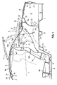
- FIG. 1 shows a side view of a so-called open car according to the present embodiment
- this open car comprises a front header 3 which extends in a vehicle width direction and supports an upper side of a windshield 2 at a front portion of a vehicle compartment 1 , and a roof RO which extends rearward from the front header 3 and forms an upper portion of the vehicle compartment 1 .
- the roof RO is split into a front roof 4 and a rear roof 5 , which are supported to be openable.
- the roofs 4 , 5 in the closed state are illustrated by solid lines
- the roofs 4 , 5 in the middle state of roof opening are illustrated by two-dotted broken lines ⁇
- the roofs 4 , 5 in the open state in which they are stored in a roof-storage space 14 which will be described below, are illustrated by two-dotted broken lines ⁇ .
- the front header 3 is formed by a front header outer 3a and a front header inner 3b which are joined to each other, and it has closed cross section 3c which extends in the vehicle width direction. Both ends of the front header 3 are connected to hinge pillars via respective front pillars which have a structure with a closed cross section (not illustrated).
- the front pillars and the hinge pillars are vehicle-body rigidity members which have a structure with a closed cross section, respectively.
- a floor panel 6 which forms a bottom face of the vehicle compartment 1 is provided.
- a rear floor 8 which extends substantially horizontally is connected to a rear portion of the floor panel 6 via a kick-up portion 7 which rises substantially upward and rearward obliquely.
- a concave spare tire pan 9 is formed at a middle are of a rear portion of the rear floor 8 .
- a rear end panel 10 which extends substantially vertically is attached to the rear end of the rear floor 8 .
- a rear end member 11 which extends in the vehicle width direction is joined to the outside of an upper portion of the rear end panel 10 .
- a rear end closed cross section 12 is formed between the rear end member 11 and the rear end panel 10 so as to extend in the vehicle width direction, which increases the rigidity of a vehicle rear portion.
- a rear bulkhead 13 which forms the rear end of the vehicle compartment 1 is attached to a middle portion of the rear floor 8 in a longitudinal direction of the vehicle.
- the rear bulkhead 13 extends substantially vertically and forms the roof-storage space 14 which is positioned in front of it.
- the roof-storage space 14 which stores the roof RO is formed between a passenger's seat 19 , which will be described later, and the rear bulkhead 13 .
- a baggage space, i.e., a trunk room 15 is preferably formed behind the rear bulkhead 13 .
- a trunk lid 16 opens or closes an upper portion of the trunk room 15 .
- the roof-storage space 14 is provided at the rear portion of the vehicle compartment 1 , and it is a storage portion to store the rear roof 5 when the roof is open, as shown by the two-dotted broken line in FIG. 1 .
- the rear bulkhead 13 has a joining piece 13a which bends forward at its lower end, and a bend portion 13b which bends forward at its upper end.
- An upper portion of the rear bulkhead 13 is formed by a substantially U-shaped portion 13c which includes the bend portion 13b , which can increase the rigidity itself.
- the seat 19 (passenger's seat) in which a passenger is seated is provided on the floor panel 6 via plural seat brackets 17 , 18 (or a cross member).
- the seat 19 comprises a seat cushion 19C and a seatback 19B which is equipped with a headrest 19H .
- this car is a two-passenger car equipped with a driver's seat and a passenger's seat.
- the invention is not limited to this kind of car, but can also be applied to a car having two or three rows of seats.
- the above-described front header 3 forms a rigidity member which extends in the vehicle width direction in front of the seat 19 arranged in the vehicle compartment 1 , and supports an upper side of the windshield 2 .
- a cross member 20 which extends substantially in the vehicle width direction is attached to a corner portion of the back face of the kick-up portion 7 and the front lower face of the rear floor 8 so that a closed cross section 21 is formed among the members 7 , 8 and 20 .
- the rigidity of the vehicle-body lower portion can be increased.
- a rear cross member 22 which extends substantially in the vehicle width direction is attached to the lower face of a middle portion of the rear floor 8 so that a closed cross section 23 is formed between the rear floor 8 and the rear cross member 22 to increase the rigidity of the vehicle-body lower portion.
- a sub frame, not illustrated, is attached to a lower portion of the rear cross member 22 .
- a rear deck member 24 is fixed to the above-described U-shaped portion 13c of the rear bulkhead 13 so as to cover the U-shaped portion 13c substantially from behind, so that a rear-deck closed cross section 25 which extends substantially in the vehicle width direction is formed between the rear bulkhead 13 and the rear deck member 24 to increase the rigidity of a vehicle-body rear deck portion 26 .
- the rear deck member 24 is formed so as to have a U-shaped or V-shaped section which has an opening substantially on the front.
- the rear deck member 24 which is a rigidity member extending in the vehicle width direction is provided at the rear deck portion 26 .
- the rear deck member 24 extends substantially in the vehicle width direction, and its both ends bend substantially forward and have forward bend portions 24R , 24R .
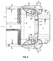
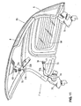
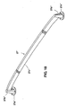
- Rollover protecting members 27 , 27 are attached to upper portions of the forward bend portions 24R , 24R .
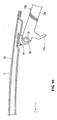
- the rollover protecting members 27 which are preferably made of a hollow member as shown in FIG. 6 , support the vehicle together with the front header 3 at the vehicle rollover, which ensures the safety of the passenger.
- the height of the rollover protecting member 27 is set so that a line L connecting the upper end of the rollover protecting member 27 and the upper end of the front header 3 can be positioned so as to protect the passenger X as shown in FIG. 1 .
- the height of the rollover protecting member 27 is set so that this line L is positioned at a level higher than the upper end of the seatback 19B (the upper end of the headrest 19H ) of the seat 19 in the vehicle compartment 1 .
- the plural rollover protecting members 27 , 27 (two members according to the present embodiment in FIG. 2 ) is arranged at the both sides behind the roof-storage space 14 , and these members 27 , 27 are attached to the forward bend portions 24R , 24R of the rear deck member 24 .
- a tunnel portion 28 is formed at the middle portion of the floor panel 6 .
- the tunnel portion 28 projects toward the vehicle compartment 1 and extends longitudinally.
- Side sills 29 , 29 having a structure with a closed cross section respectively are fixed to the right and left sides of floor panel 6 , respectively.
- the side sill 29 is formed by a side sill inner and a side sill outer which are joined to each other, and extends longitudinally. Between the side sill inner and the side sill outer is formed a side-sill closed cross section which extends longitudinally.
- rear side frames 30 , 30 which extend substantially longitudinally are fixed to the both sides of a lower portion of the rear floor 8 .
- a rear-side closed cross section 31 (see FIG. 3 ) is formed between the rear floor 8 and the rear side frame 30 so as to extend longitudinally, thereby increasing the rigidity of the vehicle-body lower portion.
- Right and left rear wheel houses 32 , 32 are formed on the outside of the rear side frames 30 , 30 as shown in FIG. 2 .
- Each wheel house 32 is made by a wheel house outer 33 and a wheel house inner 34 which are joined to each other.
- the rollover protecting members 27 are arranged on the rear deck portion 26 above the rear wheel houses 32 in back of the vehicle compartment 1 .
- a wheel-house reinforcement 35 is provided at the rear wheel house 32 for reinforcement.
- the above-described rollover protecting member 27 is provided at a position which corresponds to the wheel-house reinforcement 35 , so hereinafter, the structure of the wheel-house reinforcement 35 and its surroundings will be described in detail referring to FIGS. 3 and 4 .
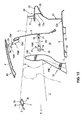
- the rear wheel house 32 of a rear wheel 36 is formed by the wheel house inner 34 and the wheel house outer 33 , and an outside portion of the rear wheel house 32 is formed by a rear-fender reinforcement 38 which extends between a rear-quarter panel inner 37 and the wheel house outer 33 and a rear fender 39 which is located on the outside of the member 38 .
- a suspension housing 40 which supports a damper SD of a rear suspension mechanism is formed on the outside of the rear side frame 30 .
- a suspension housing gusset 41 which has an arc shape in the plan view is joined to a skirt portion of the suspension housing 40 so as to surround the skirt portion.
- the suspension housing gusset 41 extends substantially upward and is joined to the wheel house inner 34 .
- the suspension housing gusset 41 is, as shown in FIG. 4 , joined to a pair of package junctions 42 , 43 which are away from each other longitudinally. Between the package junctions 42 , 43 is disposed a suspension-housing reinforcement 44 which extends substantially vertically, which is joined to the front and rear package junctions 42 , 43 .
- the front and rear package junctions 42 , 43 have joint flanges 42a at their lower edges, and are joined to an inner face of the wheel house inner 34 and an inner face of a rear-quarter panel inner 37 as a vehicle-body side wall.
- the above-described suspension-housing reinforcement 44 which is disposed between the package junctions 42 , 43 is joined to these members 42 , 43 .
- junction lower member 45 As shown in FIG. 4 , between the package junctions 42 , 43 is disposed a junction lower member 45 at the middle position in the vertical direction, which is joined to the rear bulkhead 13 .
- a junction upper member 46 which is located between the package junctions 42 , 43 is arranged at the upper edge of the suspension-housing reinforcement 44 .
- the junction upper member 46 is joined to the suspension-housing reinforcement 44 , the package junctions 42 , 43 , and the rear-quarter panel inner 37 , respectively.
- the junction upper member 46 has an opening 46a, and a shoulder belt (not illustrated) is pulled out of a belt retractor (not illustrated) through this opening 46a.
- suspension-housing reinforcement 44 which is located on the inside of the wheel house inner 34 and the rear-quarter panel inner 37 which form the vehicle-body side wall, is joined to the wheel house inner 34 at its lower end.
- the upper end of the reinforcement 44 extends substantially horizontally and is joined to an inner portion of the junction upper member 46 .
- An outside end portion of the junction upper member 46 is joined to the rear-quarter panel inner 37 .
- a closed cross section 47 is formed among the members 46, 37, 34, 44 .
- junctions 42, 43 , suspension-housing reinforcement 44 , junction lower member 45 , and junction upper member 46 form the above-described wheel-house reinforcement 35 which reinforces the rear wheel house 32 .
- the bend portion 13b of the rear bulkhead 13 is fixed to the junction upper member 46 which forms the wheel-house reinforcement 35 .
- an anchor reinforcement 48 is attached substantially vertically to the U-shaped portion 13c of the rear bulkhead 13 .
- the damper SD of the rear wheel 36 constitutes the rear suspension mechanism.
- a multi link type of suspension including upper arms, lower arms, knuckle and so on may be applied as the rear suspension mechanism including the damper SD .
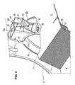
- the damper SD comprises, as shown in FIG. 3 , a cylindrical damper support 49 , an upper spring sheet 50 which is fixed to its lower end, and a lower spring sheet 51 which is positioned below.
- a coil spring 52 is arranged between the upper and lower sheets 50 , 51 .
- first gusset 61 To the suspension-housing reinforcement 44 are attached a first gusset 61 , a second gusset 62 , and a third gusset 63 which support the damper support 49 which projects substantially upward from the suspension housing 40 .
- the first gusset 61 is a member which has a U-shaped cross section and includes upper and lower horizontal plate-shaped portions 61a, 61b . These plate-shaped portions 61a, 61b have holes 61c, 61d at their center for allowing the damper support 49 to extend through these holes. Further, plural flanges 61e are formed at the plate-shaped portions 61a, 61b . The flanges 61e are joined to the suspension-housing reinforcement 44 .
- Attaching faces 61f, 61f are formed longitudinally at a portion of the first gusset 61 which corresponds to the roof-storage space 14 .
- a recess portion 61g is formed between these attaching faces 61f, 61f , and nuts 64, 64 are welded to the back faces of the attaching faces 61f, 61f.
- the first gusset 61 is attached to the suspension-housing reinforcement 44 as shown in FIG. 3 .
- the second gusset 62 extends substantially upward from the first gusset 61 and is preferably joined to the rear bulkhead 13 and/or the rear deck member 24 via the junction lower member 45 .
- This second gusset 62 which extends substantially vertically comprises, as shown in FIG.
- a gusset main plate 62a a protruding portion 62b which is formed at a portion of the gusset main plate 62a which corresponds to the damper support 49 and protrudes toward the roof-storage space 14 , a notch portion 62c which is formed below the protruding portion 62b , and flange portions 62d ...which are integrally formed with the upper edge of the gusset main plate 62a .
- the attaching faces 62e, 62e preferably have bolt through holes 65 , 65 .
- the third gusset 63 which is disposed on the side of the roof-storage space 14 of the second gusset 62 , is formed in a substantially V shape as shown in FIG. 5 . Its front portion 63b and rear portion 63c are located upward and outward relative to its middle portion 63a .
- the middle portion 63a of the third gusset 63 has a couple of bolt through holes 66, 66, and each of the front and rear portions 63b, 63c has a bolt hole 67 .
- the first and second gussets 61 , 62 are welded to the vehicle body in advance, and bolts 68 , 68 are fasted with nuts 64 , 64 after the damper SD is attached.
- the third gusset 63 is fixed to the gussets 61 , 62 .
- the third gusset 63 is fixed to a bracket 70 of the damper support 49 with bolts 69 , 69 .
- the upper end of the damper SD which is coupled to the rear wheel 36 is supported at the upper portion of the rear wheel house 32 .
- the above-described rollover protecting member 27 is disposed at a position which corresponds to a damper support portion 71 which comprises the first, second and third gussets 61, 62, 63 and the suspension-housing reinforcement 44 .
- FIG. 6 is a partial enlarged sectional view of FIG. 3 .
- the rollover protecting member 27 has preferably a hollow structure and/or comprises a flange portion 27a and a taper corn portion 27b .
- Some nuts 53 are preferably welded to the lower face of the junction upper member 46 and the lower face of the bend portion 13b of the rear bulkhead 13 , and bolts 54 are preferably fastened from above.
- the rollover protecting member 27 is attached to the rear deck portion 26 .
- the bolts 54 and nuts 53 may be arranged upside down. That is, weld bots may be attached to the junction upper member 46 and the rear bulkhead 13 , and nuts are fastened to these bolts from the above, thereby attaching the rollover protecting member 27 to the rear deck portion 26 .
- a modified structure shown in FIG. 15 may be applied in place of the structure shown in FIG. 6 .
- the flange portion 27a and the taper corn portion 27b are formed separately.
- a thread hole 56 is formed at the inner periphery of the flange portion 27a
- a thread portion 57 is formed at a lower straight portion of the periphery of the taper corn portion 27b .
- the taper corn portion 27b is fixed to the flange portion 27a via engagement between the thread hole and portion 56 , 57 .
- FIG. 7 is a side view in a roof-closed state.
- FIG. 8 is a side view in the middle state of roof opening.
- FIG. 9 is a side view in a roof-open state.
- FIG. 10 is a partial enlarged sectional view of FIG. 7 .
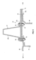
- FIG. 11 is a schematic perspective view showing the roof opening structure for a vehicle.
- a support mechanism 73 which substantially horizontally supports the roof RO which is stored in the roof-storage space 14 so that an upper space of the roof-storage space 14 between the seat 19 and the rear bulkhead 13 is covered with the front roof 4 of the roof RO .
- the roof RO is split into two parts, the front roof 4 and the rear roof 5 .
- the rear roof 5 is positioned inside the roof-storage space 14 and the front roof 4 is positioned above the rear roof 5 and covers over the roof-storage space 14 .
- the support mechanism 73 comprises a link 73A and another link 73B .
- a base portion of the link 73A is rotatably supported at the rear-quarter panel inner 37 (see FIG. 4 ) via a support axis 74 and a bracket 75 .
- the other end of the link 73A is coupled to a bracket 76 at the lower face of the rear roof 5 via a pin 77 .
- this link 73B is fixed to the front lower face of the rear roof 5 .
- this link 73B includes an extension portion 73 a which extends from the rear roof 5 toward the front roof 4 .
- One end of this extension portion 73a is coupled to a bracket 78 at the rear lower face of the front roof 4 via a pin 79 .
- the support mechanism 73 which comprises the links 73A, 73B is provided at the both sides of the roof RO as shown in FIG. 11 , but only the support mechanism 73 on the right side is illustrated.
- a spring 80 is preferably provided between the pin 79 at the end portion of the link 73B and the bracket 78 of the front roof 4 so that the front roof 4 is moved rearward, keeping its forward-slant position.
- the length of a front-side portion of the front roof 4 from the pin 79 in the roof-closed state shown in FIG. 7 is preferably greater than that of a rear-side portion of the front roof 4 from the pin 79 such that the front-side portion of the front roof 4 is heavier than the rear-side portion of the front roof 4 . Consequently, the front roof 4 tends to slat forward. For this reason, a spring force of the above-descried spring 80 may be set to be properly small or the spring 80 may even be omitted.
- the roof RO of the present embodiment is preferably manually opened and closed.
- the link 3A rotates around the center of the support axis 74 and thereby the rear roof 5 is moved upside down and stored inside the roof-storage space 14 .
- the front roof 4 is moved rearward keeping its forward-slant position, and eventually positioned above the rear roof 5 and covers over the roof-storage space 14 substantially horizontally.
- the extension portion 73a of the link 3B has a restriction piece 73b to support the front roof 4 from below and prevent the front roof 4 from inclining forward excessively for the purpose of the excessive inclination of the front roof 4 due to the spring force of the coil spring 80 (see FIG. 10 ). Accordingly, after the front roof 4 is moved rearward keeping its forward-slant position as shown in FIG. 8 , it can cover the storage space 14 substantially horizontally as shown in FIG. 9 .
- stoppers 81, 82 are preferably provided to restrict the upper limit and the lower limit.
- the stopper 82 can surely prevent the front and rear roofs 4 , 5 and the links 73A , 73B which are in their storage positions from lowering further improperly.
- a top block 83 is provided to detachably attach the roof RO to the front header 3
- reference numeral 84 denotes a back window.
- an arrow F shows a direction of vehicle front
- an arrow R shows a direction of vehicle rear
- an arrow IN shows an inward direction of vehicle
- an arrow OUT shows an outward direction of vehicle.
- the vehicle is supported by the front header 3 and the rollover protecting members 27 because the height of the rollover protecting member 27 is set so that the line L connecting the upper end of the rollover protecting member 27 and the upper end of the front header 3 can be positioned higher than the upper end of the headrest 19H of the seatback 19B . Accordingly, the passenger X can be protected surely by the rollover protecting member 27 at the vehicle rollover.
- the rollover protecting members 27 are arranged at the positions which substantially correspond to the rear deck members 24 and the rear wheel houses 32 , the sufficient rigidity of the rollover protecting members 27 can be ensured. In particular, this ensuring of the sufficient rigidity of the rollover protecting members 27 can be achieved with the existing vehicle-body structure. Accordingly, both the compactness and the light weight of the passenger protecting structure can be provided.
- the front header 3 which extends in the vehicle width direction in front of the passenger's seat 19 which is arranged in the vehicle compartment 1 and supports the upper side of the windshield 2
- the roof RO which extends rearward from the front header 3 and forms the upper portion of the vehicle compartment 1
- the roof RO being split into plural parts and openable
- the roof-storage space 14 which is formed between the passenger's seat 19 and the rear bulkhead 13 which forms the rear end of the vehicle compartment 1 , in which the roof RO is stored when the roof RO is open
- the support mechanism 73 which substantially horizontally supports the roof RO which is stored in the roof-storage space 14 so that the upper space of the roof-storage space 14 between the passenger's seat 19 and the bulkhead 13 is covered with only one (see the front roof 4 ) of the plural parts of the roof RO (see FIGS. 7 and 9 ).
- the upper space of the roof-storage space 14 between the passenger's seat 19 and the bulkhead 13 is covered with only one (see the front roof 4 ) of the split parts of the roof RO when the roof RO is open and stored in the roof-storage space 14 , the properly simple and light structure of the roof RO without any conventional deck cover can be provided. Further, the upper of the roof-storage space 14 is covered only with this one (see the front roof 4 ) of the split parts of the roof RO , so that the appearance can be improved.
- the roof RO comprises the front roof 4 and the rear roof 5 which are split from each other, and the rear roof 5 is positioned inside the roof-storage space 14 and the front roof 4 is positioned above the rear roof 5 and covers over the roof-storage space 14 (see FIG. 9 ).
- the roof RO since the roof RO is split into the front roof 4 and the rear roof 5 , the roof structure can be made simple.
- the rear roof RO since the rear roof RO is stored inside the roof-storage space 14 and the roof-storage space is covered with the front roof 4 , specifically, the front roof 4 covers the space between the seat 19 and the rear bulkhead 13 substantially horizontally, the good appearance can be provided.
- the roof RO is configured so that the rear roof 5 is moved upside down and stored inside the vehicle compartment 1 and the front roof 4 is moved rearward and above the rear roof 5 , keeping its position thereof, and covers over the roof-storage space 14 (see FIGS. 7 and 9 ).
- the upside down move of the rear roof 5 means that the rear roof 5 turns so that the lower face of the rear roof 5 faces upward, while the upper face of the rear roof 5 faces downward, so that the position of the rear roof 5 changes from its rearward-slant position in the roof-closed state to the forward-slant position.
- the support mechanism 73 can be made simple and the roof-storage space 14 can be made compact.
- the front roof 4 is supported by the supporting mechanism 73 so as to be moved rearward, keeping its forward-slant position (see FIGS. 7 , 8 and 9 ). Thereby, since the front roof 4 can be kept in the forward-slant position during its rearward move, the front roof 4 may not receive traveling winds improperly. Consequently, the roof RO can be properly operated even during the vehicle's traveling at a low speed, thereby improving the facility.
- the rollover protecting members 27 are arranged at the rear deck portion 26 , and the height of the rollover protecting member 27 is set so that the line L connecting the upper end of the rollover protecting member 27 and the upper end of the front header 3 can be positioned so as to protect the passenger X (see FIG. 7 ). Thereby, the vertical length of the rollover protecting member 27 can be properly short to aim at the small size, so that the light weight of the rollover protecting member 27 can be achieved.
- the vehicle in case of the vehicle rollover in the open state of the roof RO , the vehicle can be supported by the front header 3 and the rollover protecting members 27 , thereby ensuring the safety of the passenger.
- the rollover protecting members 27 are arranged at the rear deck portion 26 , the vehicle compartment 1 can be made spacious and also the rollover protecting members 27 can be properly provided. As a result, the vehicle compartment 1 can be used widely and the passenger can be protected properly with the rollover protecting members 27 .
- the vertical length of the rollover protecting member 27 is properly short, so that the appearance can be improved from the design aspect and the better rear view can be ensured. Further, the height of the rollover protecting member 27 is set so that the line L connecting the upper end of the rollover protecting member 27 and the upper end of the front header 3 can be positioned above the upper end of the passenger's seat 19 (see FIG. 7 ).
- the passenger's seat 19 is set so as to correspond to the size of the passenger, so that the passenger can be protected surely at the vehicle rollover by setting the height of the rollover protecting member 27 .
- FIGS. 12 - 14 A second embodiment is shown in FIGS. 12 - 14 .
- FIG. 12 is a side view in the roof-closed state
- FIG. 13 is a side view in the middle state of opening of the roof RO
- FIG. 14 is a side view in the roof-open state.
- While the L-shaped link in the side view is used as the link 73A of the support mechanism 73 in the embodiment shown in FIGS. 1 - 11 , the present embodiment shown in FIGS. 12 - 14 uses a substantially straight-line shaped link as a link 73A' of a support mechanism 73' .
- a short link having an extension portion 73a' , a restriction portion 73b' , and an attaching portion 73c' is used as a link 73B ' in the present embodiment.
- the light weight and cost reduction of the links 73A' , 73B' can be achieved.
- the other structures, operations and advantages of the present embodiment shown in FIGS. 12 - 14 are substantially the same as those of the above-described embodiment. Accordingly, the same components/structures of FIGS. 12 - 14 as those of the above-descried embodiment are denoted by the same reference characters, detailed descriptions of which are omitted.
- a third embodiment shown in FIG. 16 may be applied in place of the above-described embodiment shown in FIG. 2 .
- a rollover protecting member 27' is further provided at a central portion of the rear deck portion 26 in the vehicle width direction, in addition to the rollover protecting members 27 at the both sides which are shown in FIG. 2 .
- the rollover protecting member comprises plural members 27 , 27' which are away from each other in the vehicle width direction, in total three members in the present embodiment. Thereby, the passenger can be surely protected by the plural rollover protecting members 27 , 27' even in case the vehicle rolls over in various manners as well, like the above-described embodiments 1 and 2.
- FIGS. 17 and 18 A fourth embodiment shown in FIGS. 17 and 18 may be also applied alternatively.
- a rollover protecting member 27" which comprises a pair of disc portions 27a", 27a" and taper corn portions 27b" , 27b" which is provided at the rear deck member 24 at the both sides, and a connecting member 27c" which interconnects the both-side taper corn portions 27b" , 27b" .
- the rollover protecting member 27" comprises the member 27c" which extends substantially in the vehicle width direction.
- the passenger X can be surely protected by the rollover protecting member 27" which extends in the vehicle width direction even in case the vehicle rolls over in various manners, and the rigidity of the vehicle body can be increased properly by this protecting member.
- FIGS. 19 through 24 A fifth embodiment of the present invention will be described referring to FIGS. 19 through 24 .
- a door 55 is provided at the side of the vehicle compartment 1 to be openable.
- This door 55 preferably comprises a door inner panel 56 and a door outer panel 57 which are joined to each other as shown in FIG. 22 .
- Inside the door 55 are attached door impact bars 58 , 59 which extend substantially in the longitudinal direction of the vehicle as shown in FIGS. 19 and 22 .
- a rear side gusset 90 which extends substantially vertically and interconnects a side portion of a horizontal portion 13H of the rear bulkhead 13 and a rear quarter-panel inner 37 as a rear side panel.
- This rear side gusset 90 preferably comprises, as shown in FIG. 23 , a front piece 90a , a rear piece 90b , a side piece 90c which connects the both pieces 90a , 90b , and an upper piece 90d .
- a joint flange 90e is formed integrally at the front piece 90a on the vehicle outside
- a joint flange 90f is formed integrally at the lower end of the front piece 90a
- a joint flange 90g is formed integrally at the rear piece 90b on the vehicle outside.
- a joint flange 90h is formed integrally at the lower end of the rear piece 90b
- a joint flange 90i is formed integrally at the lower portion of the side piece 90c on the vehicle inside
- a joint flange 90j is formed integrally at the upper portion of the upper piece 90d on the vehicle outside.
- the joint flanges 90e , 90g , 90j are joined to the rear quarter-panel inner 37 as the rear side panel, the joint flange 90 is joined to the kick-up portion 7 , and the joint flanges 90h , 90i are joined to the horizontal portion 13H of the rear bulkhead 13 .
- the rear side gusset 90 is provided so that a closed cross section 91 (see FIG. 22 ) is formed by the horizontal portion 13H of the rear bulkhead 13 and the rear quarter-panel inner 37 . Further, as shown in FIGS.
- the rear side gusset 90 is provided at the position which corresponds to the side end portion of the above-described rear cross member 20 which is formed at the horizontal portion 13H of the rear bulkhead 13 and extends substantially in the vehicle width direction as a vehicle-body rigidity member.
- the rear side gusset 90 extends substantially vertically along the rear quarter-panel inner 37 and includes an extension portion 90EX which extends substantially in the vehicle width direction along the rear cross member 20 .
- the rear side gusset 90 includes a retreat portion 90SH at its inside portion which prevents its interference with the roof RO (rear roof 5 ) which is stored in the roof-storage space 14 .
- the side piece 90c of the rear side gusset 90 is formed in a curve shape so as to be concave relative to a line Y connecting the upper and lower ends of the side piece 90c as shown in FIG. 23 . This concave structure forms the retreat portion 90SH .
- the upper piece 90d of the rear side gusset 90 includes a concave attaching portion 90k on the vehicle inside.
- a shoulder anchor bracket 92 is attached to this attaching portion 90k as a reinforcing member via a fastening means such as a bolt 92V and a nut 92N or a welding means as shown in FIGS. 21 and 22 .
- the shoulder anchor bracket 92 may be made of a rectangular pipe.
- This shoulder anchor bracket 92 which is a bracket for fixing a shoulder anchor 94 of a seatbelt 93 for the passenger seated in the seat 19 , is joined to the attaching portion 90k at the upper portion of the rear side gusset 90 at its front portion.
- the shoulder anchor bracket 92 is configured to extend rearward, and the shoulder anchor 94 is provided at the upper face of a rear portion of the shoulder anchor bracket 92 via an attaching member 95 .
- the shoulder anchor bracket 92 is formed substantially in an L shape in the plan view, and the shoulder anchor bracket 92 bends inward at its rear portion and the above-described shoulder bracket 94 is attached to the upper face of this inward bent portion of the bracket 92 .
- a retractor device 96 which winds up the seatbelt 93 is provided. As shown in FIGS. 21 and 22 , this retractor device 96 is attached to a high-rigidity portion of the kick-up portion 7 which corresponds to the above-described rear cross member 20 . Meanwhile, as shown in FIG. 21 , a lap anchor 97 is attached to the body side (vehicle-body inner wall) near the floor panel 6 . The seatbelt 93 (so-called webbing), which is coupled to the lap anchor 97 , extends downward passing through a belt guide hole of the shoulder anchor 94 and connects to the above-described retractor device 96 .
- webbing webbing
- a tongue 98 is applied at the middle of the seatbelt 98 , and the tongue 98 engages with a buckle (not illustrated) on the side of the seat cushion 19C .
- the three point type of seatbelt device is provided to restrain the passenger.
- a rear end of the upper-side door impact bar 58 is provided so as to overlap with the rear side gusset 90 when viewed from the side.
- a floor frame 99 is a rigidity member which is joined to the lower face of the floor panel 6 and extends substantially longitudinally.
- the rear side gusset 90 which extends substantially vertically and interconnects the side portion (specifically, the side portion of the horizontal portion 13H ) of the rear bulkhead 13 and the rear side panel (see the rear quarter-panel inner 37 ) (see FIGS. 19 and 21 ).
- the rear side gusset 90 preferably includes the substantially closed cross section 91 which is formed by the rear bulkhead 13 and the rear side panel (see the rear quarter-panel inner 37 ) (see FIG. 22 ).
- the vehicle-body rigidity, the resistance against the vehicle side crash, and the vehicle-body torsional rigidity can be further improved.
- the rear cross member 20 which extends substantially in the vehicle width direction is provided at the rear bulkhead 13 , and the rear side gusset 90 is provided at the position which corresponds to the side end portion of the rear cross member 20 (see FIG. 21 ).
- the vehicle-body rigidity is improved, in particular, the impact load caused by the vehicle side crash can be transmitted to the rear cross member 20 properly, thereby achieving the improvement of the resistance against the vehicle side crash.
- the vehicle-body rigidity can be further improved by the synergy effect of the rear cross member 20 and the rear side gusset 90 .
- the rear side gusset 90 extends substantially vertically along the rear side panel (see the rear quarter-panel inner 37 ) and includes the extension portion 90EX which extends substantially in the vehicle width direction along the rear cross member 20 (see FIGS. 21 and 23 ).
- the extension portion 90EX with a laterally long span receives the side-impact load, so that the resistance against the vehicle side crash can be improved and the improvements of the vehicle-body rigidity and the vehicle-body torsional rigidity can be achieved.
- the rear side gusset 90 also includes the retreat portion 90SH at its inside portion which prevents any interference thereof with the roof RO which is stored in the roof-storage space 14 (see FIGS. 21 and 23 ). Thereby, any improper interference between the roof RO (the rear roof 5 ) stored in the roof-storage space 14 and the rear side gusset 90 can be prevented.
- the door 55 is provided at the side of the vehicle compartment 1 to be openable, and the rear end of the door impact bar 58 which extends substantially longitudinally inside the door 55 is provided so as to overlap with the rear side gusset 90 when viewed from the side (see FIG. 19 ). Thereby, the door 55 can be prevented from moving inward improperly at the vehicle side crash. Further, the impact load caused by the vehicle side crash can be transmitted to the rear side gusset 90 properly, thereby achieving the further improvement of the resistance against the vehicle side crash.
- FIG. 25 shows a modification of the rear side gusset 90 .
- plural beads 90m... which extend substantially in the vehicle width direction are formed at the rear side gusset 90 .
- the strength of the rear side gusset 90 can be improved without increasing the parts number, and in particular, the resistance against the vehicle side crash can be further improved.
- a biasing means for biasing the link 73A in the direction of opening of the rear roof 5 with a small biasing force specifically a coil spring disposed between the support axis 74 and the link 73A .
- a tension of the roof RO in the roof-closed state may be ensured, and the roofs 4 , 5 may be moved with the small biasing force of this biasing means when the roof RO is opened.
Abstract
A roof RO is split into plural parts, a front roof 4 and a rear roof 5. A roof-storage space 14 is formed between a passenger's seat 19 and a rear bulkhead 13 which forms a rear end of a vehicle compartment 1, in which the roof RO is stored when the roof RO is open. There is provided a support mechanism 73 which substantially horizontally supports the roof RO which is stored in the roof-storage space 14 so that an upper space of the roof-storage space 14 between the passenger's seat 19 and the bulkhead 13 is covered with only one of the plural parts 4 of the roof RO.
Description
- The present invention relates to a roof opening structure for a vehicle, in particular, a so-called open car, which comprises a front header extending in a vehicle width direction in front of a passenger's seat arranged in a vehicle compartment and supporting an upper side of a windshield and an openable roof extending rearward from the front header and forming an upper portion of the vehicle compartment.
- In general, the so-called open car with the openable roof comprises a roll bar to protect a passenger's head when the roof is open at a vehicle rollover. This conventional open car equipped with the roll bar is disclosed in Japanese Patent Laid-Open Publication No
2007-261412 - According to the roof opening structure for a vehicle disclosed in this publication, the roof is split into three parts, i.e., a front roof panel, a middle roof panel, and a back window. Further, a deck cover is provided so as to cover these roof members which are folded and stored in a storage compartment for providing a good appearance. Herein, the above-described deck cover is retreated rearward, and then the roof is folded and stored in the storage compartment. After the storage of the roof, the deck cover is moved forward again to its normal covering position.
- According to the above-described structure disclosed in the publication, while the roof can be folded compactly longitudinally because the roof is comprised of three split members, the structure may be rather complex and the above-described deck cover may be necessary to ensure the good appearance, which may further cause the more complex structure. Thus, there are problems in that the structure would become too complex, the number of parts would become too many, the weight of the structure would become too heavy, and the costs of the structure would increase improperly.
- Accordingly, an object of the present invention is to provide a roof opening structure for a vehicle which can provide a properly simple and light structure of the roof.
- The object is solved by the roof opening structure for a vehicle according to the present invention of the independent claim. Preferred embodiments of the present invention are subject of the dependent claims.
- According to the present invention, there is provided a roof opening structure for a vehicle, comprising a roof forming an upper portion of a vehicle compartment, the roof being split into plural parts and openable, a roof-storage space formed between the passenger's seat and a rear bulkhead forming a rear end of the vehicle compartment, in which the roof is stored or storable when the roof is open, and a support mechanism configured to support said roof such that the roof is stored in the roof-storage space so that an upper space or opening of the roof-storage space between the passenger's seat and the rear bulkhead is covered with only one of the plural parts of the roof.
- Preferably, the roof opening structure further comprises a front header extending in a vehicle width direction in front of the passenger's seat and supporting an upper side of a windshield, wherein said roof extends rearward from said front header and/or said roof is substantially horizontally supported by said support mechanism.
- According to the present invention, since the upper space of the roof-storage space between the passenger's seat and the rear bulkhead is covered with only one of the split parts of the roof when the roof is open and stored in the roof-storage space, the properly simple and light structure of the roof without any conventional deck cover can be provided. In other words, the above-described one of the split parts of the roof performs the function of the conventional deck cover, so that any conventional deck cover may be omitted so as to reduce the number of parts and to simplify the roof opening structure. Further, the upper of the roof-storage space is covered only with this one of the split parts of the roof, so that the appearance can be improved.
- According to an embodiment, there is provided a roof opening structure for a vehicle, comprising a front header extending in a vehicle width direction in front of a passenger's seat arranged in a vehicle compartment and supporting an upper side of a windshield, a roof extending rearward from the front header and forming an upper portion of the vehicle compartment, the roof being split into plural parts and openable, a roof-storage space formed between the passenger's seat and a rear bulkhead forming a rear end of the vehicle compartment, in which the roof is stored when the roof is open, and a support mechanism substantially horizontally supporting the roof which is stored in the roof-storage space so that an upper space of the roof-storage space between the passenger's seat and the rear bulkhead is covered with only one of the plural parts of the roof.
- According to an embodiment of the present invention, the roof comprises a front roof and a rear roof which are split from each other, and the rear roof is positioned inside the roof-storage space and the front roof is positioned above the rear roof and covers over the roof-storage space. Thereby, since the roof is split into the front roof and the rear roof, the roof structure can be made simple. Further, since the rear roof is stored inside the roof-storage space and the roof-storage space is covered with the front roof, specifically, the front roof covers the space between the seat and the rear bulkhead substantially horizontally, the good appearance can be provided.
- According to another embodiment of the present invention, the roof is configured so that the rear roof is moved upside down and stored inside the vehicle compartment and the front roof is moved rearward and above the rear roof, preferably substantially keeping a position thereof, and covers over the roof-storage space. Thereby, since the rear roof is moved upside down and stored inside the vehicle compartment, the support mechanism can be made simple and the roof-storage space can be made compact.
- According to another embodiment of the present invention, the front roof is supported by the supporting mechanism so as to be moved rearward, substantially keeping a forward-slant position thereof. Thereby, since the front roof can be kept in the forward-slant position during its rearward move, the front roof may not receive traveling winds improperly. Consequently, the roof can be properly operated even during the vehicle's traveling at a low speed, thereby improving the facility.
- According to another embodiment of the present invention, a rollover protecting member is provided at a vehicle-body rear deck portion, the height of the rollover protecting member being set so that a line connecting an upper end of the rollover protecting member and an upper end of the front header is positioned so as to protect a passenger in the vehicle compartment. Thereby, the vertical length of the rollover protecting member can be properly short to aim at the small size, so that the light weight of the rollover protecting member can be achieved. Further, in case of the vehicle rollover when the roof is in the open state, the vehicle may be supported by the front header and the rollover protecting members, thereby ensuring the safety of the passenger. Moreover, since the rollover protecting members are provided at the rear deck portion, the vehicle compartment can be made spacious and also the rollover protecting members can be properly provided. Consequently, the vehicle compartment can be used widely and the passenger can be protected properly by the rollover protecting members. In addition, the vertical length of the rollover protecting member is properly short, so that the appearance can be improved from the design aspect and the better rear view can be ensured.
- According to another embodiment of the present invention, the height of the rollover protecting member is set so that the line connecting the upper end of the rollover protecting member and the upper end of the front header is positioned at a level higher than an upper end of the seat. Herein, the upper end of the seat may be set to an upper end of the seatback, or an upper end of a headrest portion of the seatback in case of the seatback having a headrest which is integrally formed with the seatback. Accordingly, since the passenger's seat is set so as to correspond to the size of the passenger, the passenger can be protected surely at the vehicle rollover by setting the height of the rollover protecting member.
- According to another embodiment of the present invention, the rollover protecting member comprises a member which extends substantially in the vehicle width direction. Thereby, the passenger can be surely protected by the rollover protecting member extending substantially in the vehicle width direction even in case the vehicle rolls over in various manners, and the rigidity of the vehicle body can be increased properly with this protecting member.
- According to another embodiment of the present invention, the rollover protecting member comprises plural members which are away from each other in the vehicle width direction. Thereby, the passenger can be surely protected by the rollover protecting member comprising the plural members even in case the vehicle rolls over in various manners as well.
- According to another embodiment of the present invention, the vehicle-body rear deck portion comprises a rear deck member which is preferably a rigidity member extending substantially in the vehicle width direction, and the rollover protecting member is provided at a position which substantially corresponds to the rear deck member. Thereby, the support rigidity of the rollover protecting member can be ensured, and the light weight caused by the compact structure can be achieved.
- According to another embodiment of the present invention, the rollover protecting member is provided substantially at the vehicle-body rear deck portion which is positioned above a rear wheel house. Thereby, the rollover protecting member is arranged at a position which substantially corresponds to the rear wheel house, so that the rigidity of the rollover protecting member can be ensured. In particular, the rigidity can be ensured by using the existing vehicle-body structure (rear wheel house), so that both the compactness and the light weight can be achieved.
- According to another embodiment of the present invention, an upper end of a damper which is coupled to a rear wheel is supported at an upper portion of the rear wheel house. Thereby, since the rigidity of the damper itself is high and the strength of the damper support portion is high, the reinforcement of the rollover protecting member can be achieved by using this damper support portion.
- According to another embodiment of the present invention, a wheel-house reinforcement is provided at the rear wheel house. Thereby, the rollover protecting member is provided at a position which substantially corresponds to the reinforced wheel-house reinforcement, so that the rigidity of the rollover protecting member can be further increased.
- According to another embodiment of the present invention, there is provided a rear side gusset which extends substantially vertically and interconnects a side portion of the rear bulkhead and a rear side panel which forms a side portion of the vehicle compartment. Thereby, improvements of resistance against the vehicle side crash, vehicle-body rigidity and vehicle-body torsional rigidity can be achieved without any conventional cross bar. Further, since no cross bar is provided, the roof-storage space can be properly enlarged.
- According to another embodiment of the present invention, the rear side gusset includes a substantially closed cross section which is formed by the rear bulkhead and the rear side panel. Thereby, the vehicle-body rigidity can be further improved.
- According to another embodiment of the present invention, a rear cross member which extends substantially in the vehicle width direction is provided substantially at the rear bulkhead, and the rear side gusset is provided at a position which substantially corresponds to a side end portion of the rear cross member. Thereby, the vehicle-body rigidity can be improved, in particular, the impact load caused by the vehicle side crash can be transmitted to the rear cross member properly, thereby achieving the improvement of the resistance against the vehicle side crash. Further, the vehicle-body rigidity can be further improved by a synergy effect of the rear cross member and the rear side gusset.
- According to another embodiment of the present invention, the rear side gusset extends substantially vertically along the rear side panel and includes an extension portion which extends substantially in the vehicle width direction substantially along the rear cross member. Thereby, the extension portion with a laterally long span receives the side-impact load, so that the resistance against the vehicle side crash can be improved and the improvements of the vehicle-body rigidity and the vehicle-body torsional rigidity can be achieved.
- According to another embodiment of the present invention, the rear side gusset includes a retreat portion at an inside portion thereof which prevents an interference thereof with the roof which is stored in the roof-storage space. Thereby, any improper interference between the roof stored in the roof-storage space and the rear side gusset can be prevented.
- According to another embodiment of the present invention, a door is provided at the side of the vehicle compartment, and a rear end of a door impact bar which extends substantially longitudinally inside the door is provided so as to at least partly overlap with the rear side gusset when viewed from the side. Thereby, the door can be prevented from moving inward improperly at the vehicle side crash. Further, the impact load caused by the vehicle side crash can be transmitted to the rear side gusset properly, thereby achieving the further improvement of the resistance against the vehicle side crash.
- According to another embodiment of the present invention, there is provided a rear side gusset which extends substantially upward from the rear bulkhead and/or a shoulder anchor of a seatbelt for a passenger seated in the passenger's seat is fixed to the rear side gusset. Thereby, providing the roof-storage space and the shoulder anchor can be achieved. Further, the vehicle-body rigidity can be improved by the rear side gusset. Moreover, since the shoulder anchor is fixed to the rear side gusset as a reinforcement member, the strength of the shoulder anchor can be increased.
- According to another embodiment of the present invention, there is provided a shoulder anchor bracket which is connected to the rear side gusset at a front portion thereof and extends substantially rearward, and the shoulder anchor is provided at the shoulder anchor bracket. Thereby, ensuring a proper disposition angle of the seatbelt relative to the passenger and a strong support rigidity of the shoulder anchor can be achieved.
- According to another embodiment of the present invention, a retractor device which winds up the seatbelt is attached to a kick-up portion which rises substantially upward from a floor panel. Thereby, the retractor device can be arranged at a proper position from the space standpoint, and the support rigidity of the retractor device can be ensured.
- According to a further aspect, there is provided a method of storing a roof of an open car, comprising the steps of:
- splitting or dividing a roof of a vehicle compartment into plural parts, preferably two parts;
- forming a roof-storage space between a passenger's seat and a rear bulkhead forming a rear end of the vehicle compartment,
- storing said roof within said roof-storage space when the roof (RO) is open; and
- covering an upper space or upper opening of the roof-storage space between the passenger's seat and the rear bulkhead with one of the plural parts of the roof.
- Other features, aspects, and advantages of the present invention will become apparent from the following description which refers to the accompanying drawings.
-
FIG. 1 is a side view showing a roof opening structure for a vehicle according to a first embodiment of the present invention. -
FIG. 2 is a plan view of a major portion ofFIG. 1 . -
FIG. 3 is an elevation view showing a disposition structure of a rollover protecting member. -
FIG. 4 is a perspective view showing surrounding structure of a rear wheel house and a wheel-house reinforcement on a vehicle right side. -
FIG. 5 is an exploded perspective view of each gusset. -
FIG. 6 is a partial enlarged sectional view ofFIG. 3 . -
FIG. 7 is a side view in a roof-closed state. -
FIG. 8 is a side view in the middle state of roof opening. -
FIG. 9 is a side view in a roof-open state. -
FIG. 10 is a partial enlarged sectional view ofFIG. 7 . -
FIG. 11 is a schematic perspective view showing the roof opening structure for a vehicle. -
FIG. 12 is a side view of the roof opening structure for a vehicle in the roof-closed state according to a second embodiment. -
FIG. 13 is a side view in the middle state of roof opening. -
FIG. 14 is a side view in the roof-open state. -
FIG. 15 is a plan view showing a disposition structure of a rollover protecting member according to a third embodiment. -
FIG. 16 is a plan view of a passenger protecting structure for a vehicle according to a fourth embodiment. -
FIG. 17 is a perspective view of a rollover protecting member shown inFIG. 8 . -
FIG. 18 is a sectional view of a modification of the disposition structure of a rollover protecting member. -
FIG. 19 is a side view showing a vehicle-body rear structure for a vehicle according to a fifth embodiment of the present invention. -
FIG. 20 is a plan view of a major portion ofFIG. 19 . -
FIG. 21 is a perspective view of a major portion ofFIG. 19 . -
FIG. 22 is an elevation view showing a disposition structure of a rear side gusset. -
FIG. 23 is an exploded perspective view of the rear side gusset and a shoulder anchor bracket. -
FIG. 24 is a partial enlarged sectional view showing an example of attaching structure of the shoulder anchor bracket to the rear side gusset. -
FIG. 25 is a perspective view of a modification of the rear side gusset. - Hereinafter, preferred embodiments of the present invention will be described referring to the accompanying drawings. Although the embodiments are described separately, it should be understood that single feature(s) of one embodiment may be combined with another embodiment and vice versa.
- A first embodiment of the present embodiment will be described. In a side view of
FIG. 1 which shows a roof opening structure of a so-called open car according to the present embodiment, this open car comprises afront header 3 which extends in a vehicle width direction and supports an upper side of awindshield 2 at a front portion of avehicle compartment 1, and a roof RO which extends rearward from thefront header 3 and forms an upper portion of thevehicle compartment 1. The roof RO is split into afront roof 4 and arear roof 5, which are supported to be openable. InFIG. 1 , theroofs roofs roofs storage space 14, which will be described below, are illustrated by two-dotted broken lines β. - Herein, the
front header 3 is formed by a front header outer 3a and a front header inner 3b which are joined to each other, and it has closedcross section 3c which extends in the vehicle width direction. Both ends of thefront header 3 are connected to hinge pillars via respective front pillars which have a structure with a closed cross section (not illustrated). Herein, the front pillars and the hinge pillars are vehicle-body rigidity members which have a structure with a closed cross section, respectively. - Meanwhile, a
floor panel 6 which forms a bottom face of thevehicle compartment 1 is provided. Arear floor 8 which extends substantially horizontally is connected to a rear portion of thefloor panel 6 via a kick-upportion 7 which rises substantially upward and rearward obliquely. A concavespare tire pan 9 is formed at a middle are of a rear portion of therear floor 8. Arear end panel 10 which extends substantially vertically is attached to the rear end of therear floor 8. Arear end member 11 which extends in the vehicle width direction is joined to the outside of an upper portion of therear end panel 10. A rear end closedcross section 12 is formed between therear end member 11 and therear end panel 10 so as to extend in the vehicle width direction, which increases the rigidity of a vehicle rear portion. - Further, a
rear bulkhead 13 which forms the rear end of thevehicle compartment 1 is attached to a middle portion of therear floor 8 in a longitudinal direction of the vehicle. Therear bulkhead 13 extends substantially vertically and forms the roof-storage space 14 which is positioned in front of it. Specifically, the roof-storage space 14 which stores the roof RO is formed between a passenger'sseat 19, which will be described later, and therear bulkhead 13. Further, a baggage space, i.e., atrunk room 15 is preferably formed behind therear bulkhead 13. Atrunk lid 16 opens or closes an upper portion of thetrunk room 15. - The roof-
storage space 14 is provided at the rear portion of thevehicle compartment 1, and it is a storage portion to store therear roof 5 when the roof is open, as shown by the two-dotted broken line inFIG. 1 . Herein, therear bulkhead 13 has a joiningpiece 13a which bends forward at its lower end, and abend portion 13b which bends forward at its upper end. An upper portion of therear bulkhead 13 is formed by a substantiallyU-shaped portion 13c which includes thebend portion 13b, which can increase the rigidity itself. - Meanwhile, the seat 19 (passenger's seat) in which a passenger is seated is provided on the
floor panel 6 viaplural seat brackets 17, 18 (or a cross member). Theseat 19 comprises aseat cushion 19C and aseatback 19B which is equipped with aheadrest 19H. Herein, this car is a two-passenger car equipped with a driver's seat and a passenger's seat. However, the invention is not limited to this kind of car, but can also be applied to a car having two or three rows of seats. The above-describedfront header 3 forms a rigidity member which extends in the vehicle width direction in front of theseat 19 arranged in thevehicle compartment 1, and supports an upper side of thewindshield 2. - Moreover, a
cross member 20 which extends substantially in the vehicle width direction is attached to a corner portion of the back face of the kick-upportion 7 and the front lower face of therear floor 8 so that aclosed cross section 21 is formed among themembers - Further, a
rear cross member 22 which extends substantially in the vehicle width direction is attached to the lower face of a middle portion of therear floor 8 so that aclosed cross section 23 is formed between therear floor 8 and therear cross member 22 to increase the rigidity of the vehicle-body lower portion. A sub frame, not illustrated, is attached to a lower portion of therear cross member 22. - A
rear deck member 24 is fixed to the above-describedU-shaped portion 13c of therear bulkhead 13 so as to cover theU-shaped portion 13c substantially from behind, so that a rear-deck closedcross section 25 which extends substantially in the vehicle width direction is formed between therear bulkhead 13 and therear deck member 24 to increase the rigidity of a vehicle-bodyrear deck portion 26. Herein, therear deck member 24 is formed so as to have a U-shaped or V-shaped section which has an opening substantially on the front. Thus, therear deck member 24 which is a rigidity member extending in the vehicle width direction is provided at therear deck portion 26. - As shown in
FIG. 2 which is a plan view of a major portion ofFIG. 1 , therear deck member 24 extends substantially in the vehicle width direction, and its both ends bend substantially forward and haveforward bend portions Rollover protecting members forward bend portions rollover protecting members 27, which are preferably made of a hollow member as shown inFIG. 6 , support the vehicle together with thefront header 3 at the vehicle rollover, which ensures the safety of the passenger. For this purpose, the height of therollover protecting member 27 is set so that a line L connecting the upper end of therollover protecting member 27 and the upper end of thefront header 3 can be positioned so as to protect the passenger X as shown inFIG. 1 . - Specifically, as shown in
FIG. 1 , the height of therollover protecting member 27 is set so that this line L is positioned at a level higher than the upper end of theseatback 19B (the upper end of theheadrest 19H) of theseat 19 in thevehicle compartment 1. Further, the pluralrollover protecting members 27, 27 (two members according to the present embodiment inFIG. 2 ) is arranged at the both sides behind the roof-storage space 14, and thesemembers forward bend portions rear deck member 24. - In
FIG. 2 , atunnel portion 28 is formed at the middle portion of thefloor panel 6. Thetunnel portion 28 projects toward thevehicle compartment 1 and extends longitudinally.Side sills floor panel 6, respectively. Theside sill 29 is formed by a side sill inner and a side sill outer which are joined to each other, and extends longitudinally. Between the side sill inner and the side sill outer is formed a side-sill closed cross section which extends longitudinally. - Further, rear side frames 30, 30 which extend substantially longitudinally are fixed to the both sides of a lower portion of the
rear floor 8. A rear-side closed cross section 31 (seeFIG. 3 ) is formed between therear floor 8 and therear side frame 30 so as to extend longitudinally, thereby increasing the rigidity of the vehicle-body lower portion. - Right and left rear wheel houses 32, 32 are formed on the outside of the rear side frames 30, 30 as shown in
FIG. 2 . Eachwheel house 32 is made by a wheel house outer 33 and a wheel house inner 34 which are joined to each other. - As shown in
FIGS. 1 and2 , therollover protecting members 27 are arranged on therear deck portion 26 above the rear wheel houses 32 in back of thevehicle compartment 1. A wheel-house reinforcement 35 is provided at therear wheel house 32 for reinforcement. The above-describedrollover protecting member 27 is provided at a position which corresponds to the wheel-house reinforcement 35, so hereinafter, the structure of the wheel-house reinforcement 35 and its surroundings will be described in detail referring toFIGS. 3 and4 . - As shown in
FIG. 3 , therear wheel house 32 of arear wheel 36 is formed by the wheel house inner 34 and the wheel house outer 33, and an outside portion of therear wheel house 32 is formed by a rear-fender reinforcement 38 which extends between a rear-quarter panel inner 37 and the wheel house outer 33 and arear fender 39 which is located on the outside of themember 38. - Moreover, as shown in
FIG. 3 , asuspension housing 40 which supports a damper SD of a rear suspension mechanism is formed on the outside of therear side frame 30. Asuspension housing gusset 41 which has an arc shape in the plan view is joined to a skirt portion of thesuspension housing 40 so as to surround the skirt portion. Thesuspension housing gusset 41 extends substantially upward and is joined to the wheel house inner 34. - The
suspension housing gusset 41 is, as shown inFIG. 4 , joined to a pair ofpackage junctions package junctions housing reinforcement 44 which extends substantially vertically, which is joined to the front andrear package junctions - These members form a suspension support structure. The front and
rear package junctions joint flanges 42a at their lower edges, and are joined to an inner face of the wheel house inner 34 and an inner face of a rear-quarter panel inner 37 as a vehicle-body side wall. The above-described suspension-housing reinforcement 44 which is disposed between thepackage junctions members - As shown in
FIG. 4 , between thepackage junctions lower member 45 at the middle position in the vertical direction, which is joined to therear bulkhead 13. - As shown in
FIG. 3 , a junctionupper member 46 which is located between thepackage junctions housing reinforcement 44. The junctionupper member 46 is joined to the suspension-housing reinforcement 44, thepackage junctions upper member 46 has anopening 46a, and a shoulder belt (not illustrated) is pulled out of a belt retractor (not illustrated) through thisopening 46a. - Further, the suspension-
housing reinforcement 44, which is located on the inside of the wheel house inner 34 and the rear-quarter panel inner 37 which form the vehicle-body side wall, is joined to the wheel house inner 34 at its lower end. The upper end of thereinforcement 44 extends substantially horizontally and is joined to an inner portion of the junctionupper member 46. An outside end portion of the junctionupper member 46 is joined to the rear-quarter panel inner 37. Aclosed cross section 47 is formed among themembers - The above-described
package junctions housing reinforcement 44, junctionlower member 45, and junctionupper member 46 form the above-described wheel-house reinforcement 35 which reinforces therear wheel house 32. - As shown in
FIG. 3 , thebend portion 13b of therear bulkhead 13 is fixed to the junctionupper member 46 which forms the wheel-house reinforcement 35. Moreover, ananchor reinforcement 48 is attached substantially vertically to theU-shaped portion 13c of therear bulkhead 13. - Meanwhile, the damper SD of the
rear wheel 36 constitutes the rear suspension mechanism. Herein, a multi link type of suspension including upper arms, lower arms, knuckle and so on may be applied as the rear suspension mechanism including the damper SD. - The damper SD comprises, as shown in
FIG. 3 , acylindrical damper support 49, anupper spring sheet 50 which is fixed to its lower end, and alower spring sheet 51 which is positioned below. Acoil spring 52 is arranged between the upper andlower sheets - To the suspension-
housing reinforcement 44 are attached afirst gusset 61, asecond gusset 62, and athird gusset 63 which support thedamper support 49 which projects substantially upward from thesuspension housing 40. - The structure of the
gussets FIG. 5 . As shown inFIG. 5 , thefirst gusset 61 is a member which has a U-shaped cross section and includes upper and lower horizontal plate-shapedportions portions holes damper support 49 to extend through these holes. Further,plural flanges 61e are formed at the plate-shapedportions flanges 61e are joined to the suspension-housing reinforcement 44. - Attaching
faces first gusset 61 which corresponds to the roof-storage space 14. Arecess portion 61g is formed between these attachingfaces nuts faces first gusset 61 is attached to the suspension-housing reinforcement 44 as shown inFIG. 3 . - The
second gusset 62, as shown inFIGS. 3 and5 , extends substantially upward from thefirst gusset 61 and is preferably joined to therear bulkhead 13 and/or therear deck member 24 via the junctionlower member 45. Thissecond gusset 62 which extends substantially vertically comprises, as shown inFIG. 5 , a gussetmain plate 62a, a protrudingportion 62b which is formed at a portion of the gussetmain plate 62a which corresponds to thedamper support 49 and protrudes toward the roof-storage space 14, anotch portion 62c which is formed below the protrudingportion 62b, andflange portions 62d...which are integrally formed with the upper edge of the gussetmain plate 62a. The attaching faces 62e, 62e preferably have bolt throughholes - The
third gusset 63, which is disposed on the side of the roof-storage space 14 of thesecond gusset 62, is formed in a substantially V shape as shown inFIG. 5 . Itsfront portion 63b andrear portion 63c are located upward and outward relative to itsmiddle portion 63a. Themiddle portion 63a of thethird gusset 63 has a couple of bolt throughholes rear portions bolt hole 67. - As shown in
FIG. 3 , the first andsecond gussets bolts nuts third gusset 63 is fixed to thegussets third gusset 63 is fixed to a bracket 70 of thedamper support 49 withbolts FIG. 3 , the upper end of the damper SD which is coupled to therear wheel 36 is supported at the upper portion of therear wheel house 32. Thus, the above-describedrollover protecting member 27 is disposed at a position which corresponds to adamper support portion 71 which comprises the first, second andthird gussets housing reinforcement 44. -
FIG. 6 is a partial enlarged sectional view ofFIG. 3 . Therollover protecting member 27 has preferably a hollow structure and/or comprises aflange portion 27a and ataper corn portion 27b. Somenuts 53 are preferably welded to the lower face of the junctionupper member 46 and the lower face of thebend portion 13b of therear bulkhead 13, andbolts 54 are preferably fastened from above. Thus, therollover protecting member 27 is attached to therear deck portion 26. - Herein, the
bolts 54 andnuts 53 may be arranged upside down. That is, weld bots may be attached to the junctionupper member 46 and therear bulkhead 13, and nuts are fastened to these bolts from the above, thereby attaching therollover protecting member 27 to therear deck portion 26. - Herein, a modified structure shown in
FIG. 15 may be applied in place of the structure shown inFIG. 6 . In this modification, theflange portion 27a and thetaper corn portion 27b are formed separately. Athread hole 56 is formed at the inner periphery of theflange portion 27a, and athread portion 57 is formed at a lower straight portion of the periphery of thetaper corn portion 27b. Thetaper corn portion 27b is fixed to theflange portion 27a via engagement between the thread hole andportion rollover protecting member 27 can be improved. - Next, the roof opening structure for a vehicle will be described referring to
FIGS. 7 through 11 .FIG. 7 is a side view in a roof-closed state.FIG. 8 is a side view in the middle state of roof opening.FIG. 9 is a side view in a roof-open state.FIG. 10 is a partial enlarged sectional view ofFIG. 7 .FIG. 11 is a schematic perspective view showing the roof opening structure for a vehicle. - As shown in
FIGS. 7 through 11 , particularlyFIG. 9 , when the roof RO is opened and stored in the roof-storage space 14, there is provided asupport mechanism 73 which substantially horizontally supports the roof RO which is stored in the roof-storage space 14 so that an upper space of the roof-storage space 14 between theseat 19 and therear bulkhead 13 is covered with thefront roof 4 of the roof RO. - According to the present embodiment, as shown in
FIGS. 7 ,8 and9 , the roof RO is split into two parts, thefront roof 4 and therear roof 5. As shown inFIG. 9 , therear roof 5 is positioned inside the roof-storage space 14 and thefront roof 4 is positioned above therear roof 5 and covers over the roof-storage space 14. - Thus, the
support mechanism 73 comprises alink 73A and anotherlink 73B. As shown inFIG. 11 , a base portion of thelink 73A is rotatably supported at the rear-quarter panel inner 37 (seeFIG. 4 ) via asupport axis 74 and abracket 75. The other end of thelink 73A is coupled to abracket 76 at the lower face of therear roof 5 via apin 77. - Meanwhile, the
other link 73B is fixed to the front lower face of therear roof 5. As shown inFIG. 7 , thislink 73B includes anextension portion 73a which extends from therear roof 5 toward thefront roof 4. One end of thisextension portion 73a is coupled to abracket 78 at the rear lower face of thefront roof 4 via apin 79. - As shown in
FIG. 11 , thesupport mechanism 73 which comprises thelinks FIG. 11 , but only thesupport mechanism 73 on the right side is illustrated. - Further, as shown in
FIG. 10 , aspring 80 is preferably provided between thepin 79 at the end portion of thelink 73B and thebracket 78 of thefront roof 4 so that thefront roof 4 is moved rearward, keeping its forward-slant position. Herein, the length of a front-side portion of thefront roof 4 from thepin 79 in the roof-closed state shown inFIG. 7 is preferably greater than that of a rear-side portion of thefront roof 4 from thepin 79 such that the front-side portion of thefront roof 4 is heavier than the rear-side portion of thefront roof 4. Consequently, thefront roof 4 tends to slat forward. For this reason, a spring force of the above-descriedspring 80 may be set to be properly small or thespring 80 may even be omitted. - The roof RO of the present embodiment is preferably manually opened and closed. When the roof RO is opened as shown in
FIG. 9 from the state ofFIG. 7 by way of the state shown inFIG. 8 , the link 3A rotates around the center of thesupport axis 74 and thereby therear roof 5 is moved upside down and stored inside the roof-storage space 14. Meanwhile, thefront roof 4 is moved rearward keeping its forward-slant position, and eventually positioned above therear roof 5 and covers over the roof-storage space 14 substantially horizontally. - In
FIG. 9 , theextension portion 73a of the link 3B has arestriction piece 73b to support thefront roof 4 from below and prevent thefront roof 4 from inclining forward excessively for the purpose of the excessive inclination of thefront roof 4 due to the spring force of the coil spring 80 (seeFIG. 10 ). Accordingly, after thefront roof 4 is moved rearward keeping its forward-slant position as shown inFIG. 8 , it can cover thestorage space 14 substantially horizontally as shown inFIG. 9 . - In
FIGS. 7 through 9 ,stoppers stopper 82 can surely prevent the front andrear roofs links FIG. 11 , atop block 83 is provided to detachably attach the roof RO to thefront header 3, andreference numeral 84 denotes a back window. In figures, an arrow F shows a direction of vehicle front, an arrow R shows a direction of vehicle rear, an arrow IN shows an inward direction of vehicle, and an arrow OUT shows an outward direction of vehicle. - Hereinafter, the operation of the above-described embodiment will be described. When the roof RO in the closed state shown in
FIG. 7 is opened as shown inFIG. 9 , at first the top lock 83 (seeFIG. 11 ) of the roof RO is unlocked, and then thefront roof 4 is moved rearward by the manual operation. This rearward moving force is transmitted to thelink 73B and thelink 73A via therear roof 5, so that thelink 73A rotates around thesupport axis 74 clockwise, and therear roof 5 moves to its rising position shown inFIG. 8 from its closed position shown inFIG. 7 . Thefront roof 4 which is supported by thelink 73B is moved rearward, keeping its forward-slant position with the spring force of thespring 80 and the weight balance regarding the above-describedpin 79, as shown inFIG. 8 . - As the
front roof 4 is further moved rearward from the middle state of roof opening shown inFIG. 8 , this rearward moving force is transmitted to thelink 73B and thelink 73A via therear roof 5. Accordingly, thelink 73A further rotates around thesupport axis 74 clockwise, so that therear roof 5 changes its position upside down from the state ofFIG. 8 to the state shown inFIG. 9 . Thefront roof 4 is moved above thisrear roof 5 and covers over the roof-storage space 14 substantially horizontally. - Meanwhile, in case of the vehicle rollover, while the roof RO is in the open state shown in
FIG. 9 , the vehicle is supported by thefront header 3 and therollover protecting members 27 because the height of therollover protecting member 27 is set so that the line L connecting the upper end of therollover protecting member 27 and the upper end of thefront header 3 can be positioned higher than the upper end of theheadrest 19H of theseatback 19B. Accordingly, the passenger X can be protected surely by therollover protecting member 27 at the vehicle rollover. - Further, since the
rollover protecting members 27 are arranged at the positions which substantially correspond to therear deck members 24 and the rear wheel houses 32, the sufficient rigidity of therollover protecting members 27 can be ensured. In particular, this ensuring of the sufficient rigidity of therollover protecting members 27 can be achieved with the existing vehicle-body structure. Accordingly, both the compactness and the light weight of the passenger protecting structure can be provided. - As described above, according to the roof opening structure of the open car according to the present embodiment shown in
FIGS. 1 through 11 , there are provided thefront header 3 which extends in the vehicle width direction in front of the passenger'sseat 19 which is arranged in thevehicle compartment 1 and supports the upper side of thewindshield 2, the roof RO which extends rearward from thefront header 3 and forms the upper portion of thevehicle compartment 1, the roof RO being split into plural parts and openable, the roof-storage space 14 which is formed between the passenger'sseat 19 and therear bulkhead 13 which forms the rear end of thevehicle compartment 1, in which the roof RO is stored when the roof RO is open, and thesupport mechanism 73 which substantially horizontally supports the roof RO which is stored in the roof-storage space 14 so that the upper space of the roof-storage space 14 between the passenger'sseat 19 and thebulkhead 13 is covered with only one (see the front roof 4) of the plural parts of the roof RO (seeFIGS. 7 and9 ). - According to the present embodiment, since the upper space of the roof-
storage space 14 between the passenger'sseat 19 and thebulkhead 13 is covered with only one (see the front roof 4) of the split parts of the roof RO when the roof RO is open and stored in the roof-storage space 14, the properly simple and light structure of the roof RO without any conventional deck cover can be provided. Further, the upper of the roof-storage space 14 is covered only with this one (see the front roof 4) of the split parts of the roof RO, so that the appearance can be improved. - Further, the roof RO comprises the
front roof 4 and therear roof 5 which are split from each other, and therear roof 5 is positioned inside the roof-storage space 14 and thefront roof 4 is positioned above therear roof 5 and covers over the roof-storage space 14 (seeFIG. 9 ). Thereby, since the roof RO is split into thefront roof 4 and therear roof 5, the roof structure can be made simple. Further, since the rear roof RO is stored inside the roof-storage space 14 and the roof-storage space is covered with thefront roof 4, specifically, thefront roof 4 covers the space between theseat 19 and therear bulkhead 13 substantially horizontally, the good appearance can be provided. - Moreover, the roof RO is configured so that the
rear roof 5 is moved upside down and stored inside thevehicle compartment 1 and thefront roof 4 is moved rearward and above therear roof 5, keeping its position thereof, and covers over the roof-storage space 14 (seeFIGS. 7 and9 ). - Herein, the upside down move of the
rear roof 5 means that therear roof 5 turns so that the lower face of therear roof 5 faces upward, while the upper face of therear roof 5 faces downward, so that the position of therear roof 5 changes from its rearward-slant position in the roof-closed state to the forward-slant position. Thereby, since therear roof 5 is moved upside down and stored inside thevehicle compartment 1, thesupport mechanism 73 can be made simple and the roof-storage space 14 can be made compact. - Further, the
front roof 4 is supported by the supportingmechanism 73 so as to be moved rearward, keeping its forward-slant position (seeFIGS. 7 ,8 and9 ). Thereby, since thefront roof 4 can be kept in the forward-slant position during its rearward move, thefront roof 4 may not receive traveling winds improperly. Consequently, the roof RO can be properly operated even during the vehicle's traveling at a low speed, thereby improving the facility. - In addition, the
rollover protecting members 27 are arranged at therear deck portion 26, and the height of therollover protecting member 27 is set so that the line L connecting the upper end of therollover protecting member 27 and the upper end of thefront header 3 can be positioned so as to protect the passenger X (seeFIG. 7 ). Thereby, the vertical length of therollover protecting member 27 can be properly short to aim at the small size, so that the light weight of therollover protecting member 27 can be achieved. - Further, in case of the vehicle rollover in the open state of the roof RO, the vehicle can be supported by the
front header 3 and therollover protecting members 27, thereby ensuring the safety of the passenger. Moreover, since therollover protecting members 27 are arranged at therear deck portion 26, thevehicle compartment 1 can be made spacious and also therollover protecting members 27 can be properly provided. As a result, thevehicle compartment 1 can be used widely and the passenger can be protected properly with therollover protecting members 27. - In addition, the vertical length of the
rollover protecting member 27 is properly short, so that the appearance can be improved from the design aspect and the better rear view can be ensured. Further, the height of therollover protecting member 27 is set so that the line L connecting the upper end of therollover protecting member 27 and the upper end of thefront header 3 can be positioned above the upper end of the passenger's seat 19 (seeFIG. 7 ). - The passenger's
seat 19 is set so as to correspond to the size of the passenger, so that the passenger can be protected surely at the vehicle rollover by setting the height of therollover protecting member 27. - A second embodiment is shown in
FIGS. 12 - 14 .FIG. 12 is a side view in the roof-closed state,FIG. 13 is a side view in the middle state of opening of the roof RO, andFIG. 14 is a side view in the roof-open state. - While the L-shaped link in the side view is used as the
link 73A of thesupport mechanism 73 in the embodiment shown inFIGS. 1 - 11 , the present embodiment shown inFIGS. 12 - 14 uses a substantially straight-line shaped link as alink 73A' of a support mechanism 73'. - Further, a short link having an
extension portion 73a', arestriction portion 73b', and an attachingportion 73c' is used as alink 73B' in the present embodiment. Thereby, the light weight and cost reduction of thelinks 73A', 73B' can be achieved. The other structures, operations and advantages of the present embodiment shown inFIGS. 12 - 14 are substantially the same as those of the above-described embodiment. Accordingly, the same components/structures ofFIGS. 12 - 14 as those of the above-descried embodiment are denoted by the same reference characters, detailed descriptions of which are omitted. - A third embodiment shown in
FIG. 16 may be applied in place of the above-described embodiment shown inFIG. 2 . According to the present embodiment, a rollover protecting member 27' is further provided at a central portion of therear deck portion 26 in the vehicle width direction, in addition to therollover protecting members 27 at the both sides which are shown inFIG. 2 . - That is, the rollover protecting member comprises
plural members 27, 27' which are away from each other in the vehicle width direction, in total three members in the present embodiment. Thereby, the passenger can be surely protected by the pluralrollover protecting members 27, 27' even in case the vehicle rolls over in various manners as well, like the above-describedembodiments - A fourth embodiment shown in
FIGS. 17 and18 may be also applied alternatively. In the present embodiment, there is provided arollover protecting member 27" which comprises a pair ofdisc portions 27a", 27a" and tapercorn portions 27b", 27b" which is provided at therear deck member 24 at the both sides, and a connectingmember 27c" which interconnects the both-sidetaper corn portions 27b", 27b". - That is, the
rollover protecting member 27" comprises themember 27c" which extends substantially in the vehicle width direction. Thereby, the passenger X can be surely protected by therollover protecting member 27" which extends in the vehicle width direction even in case the vehicle rolls over in various manners, and the rigidity of the vehicle body can be increased properly by this protecting member. - A fifth embodiment of the present invention will be described referring to
FIGS. 19 through 24 . - As shown in
FIGS. 19 and22 , adoor 55 is provided at the side of thevehicle compartment 1 to be openable. Thisdoor 55 preferably comprises a doorinner panel 56 and a doorouter panel 57 which are joined to each other as shown inFIG. 22 . Inside thedoor 55 are attached door impact bars 58, 59 which extend substantially in the longitudinal direction of the vehicle as shown inFIGS. 19 and22 . - Further, as shown in
FIGS. 19 through 22 , there is provided arear side gusset 90 which extends substantially vertically and interconnects a side portion of ahorizontal portion 13H of therear bulkhead 13 and a rear quarter-panel inner 37 as a rear side panel. Thisrear side gusset 90 preferably comprises, as shown inFIG. 23 , afront piece 90a, arear piece 90b, aside piece 90c which connects the bothpieces upper piece 90d. Further, ajoint flange 90e is formed integrally at thefront piece 90a on the vehicle outside, ajoint flange 90f is formed integrally at the lower end of thefront piece 90a, and ajoint flange 90g is formed integrally at therear piece 90b on the vehicle outside. Moreover, ajoint flange 90h is formed integrally at the lower end of therear piece 90b, ajoint flange 90i is formed integrally at the lower portion of theside piece 90c on the vehicle inside, and ajoint flange 90j is formed integrally at the upper portion of theupper piece 90d on the vehicle outside. - Herein, as shown in
FIGS. 21 and22 , thejoint flanges joint flange 90 is joined to the kick-upportion 7, and thejoint flanges horizontal portion 13H of therear bulkhead 13. Thus, therear side gusset 90 is provided so that a closed cross section 91 (seeFIG. 22 ) is formed by thehorizontal portion 13H of therear bulkhead 13 and the rear quarter-panel inner 37. Further, as shown inFIGS. 21 and22 , therear side gusset 90 is provided at the position which corresponds to the side end portion of the above-describedrear cross member 20 which is formed at thehorizontal portion 13H of therear bulkhead 13 and extends substantially in the vehicle width direction as a vehicle-body rigidity member. - Further, as shown in
FIGS. 21 and23 , therear side gusset 90 extends substantially vertically along the rear quarter-panel inner 37 and includes an extension portion 90EX which extends substantially in the vehicle width direction along therear cross member 20. As shown inFIG. 23 , therear side gusset 90 includes a retreat portion 90SH at its inside portion which prevents its interference with the roof RO (rear roof 5) which is stored in the roof-storage space 14. Herein, theside piece 90c of therear side gusset 90 is formed in a curve shape so as to be concave relative to a line Y connecting the upper and lower ends of theside piece 90c as shown inFIG. 23 . This concave structure forms the retreat portion 90SH. - Further, as shown in
FIG. 23 , theupper piece 90d of therear side gusset 90 includes a concave attachingportion 90k on the vehicle inside. Ashoulder anchor bracket 92 is attached to this attachingportion 90k as a reinforcing member via a fastening means such as abolt 92V and anut 92N or a welding means as shown inFIGS. 21 and22 . Theshoulder anchor bracket 92 may be made of a rectangular pipe. Thisshoulder anchor bracket 92, which is a bracket for fixing ashoulder anchor 94 of aseatbelt 93 for the passenger seated in theseat 19, is joined to the attachingportion 90k at the upper portion of therear side gusset 90 at its front portion. Theshoulder anchor bracket 92 is configured to extend rearward, and theshoulder anchor 94 is provided at the upper face of a rear portion of theshoulder anchor bracket 92 via an attachingmember 95. In the present embodiment, theshoulder anchor bracket 92 is formed substantially in an L shape in the plan view, and theshoulder anchor bracket 92 bends inward at its rear portion and the above-describedshoulder bracket 94 is attached to the upper face of this inward bent portion of thebracket 92. - Moreover, a
retractor device 96 which winds up theseatbelt 93 is provided. As shown inFIGS. 21 and22 , thisretractor device 96 is attached to a high-rigidity portion of the kick-upportion 7 which corresponds to the above-describedrear cross member 20. Meanwhile, as shown inFIG. 21 , alap anchor 97 is attached to the body side (vehicle-body inner wall) near thefloor panel 6. The seatbelt 93 (so-called webbing), which is coupled to thelap anchor 97, extends downward passing through a belt guide hole of theshoulder anchor 94 and connects to the above-describedretractor device 96. Further, atongue 98 is applied at the middle of theseatbelt 98, and thetongue 98 engages with a buckle (not illustrated) on the side of theseat cushion 19C. Thus, the three point type of seatbelt device is provided to restrain the passenger. - Herein, as shown in the side view of
FIG. 19 , a rear end of the upper-sidedoor impact bar 58 is provided so as to overlap with therear side gusset 90 when viewed from the side. InFIG. 22 , afloor frame 99 is a rigidity member which is joined to the lower face of thefloor panel 6 and extends substantially longitudinally. - According to the present embodiment, there is provided the
rear side gusset 90 which extends substantially vertically and interconnects the side portion (specifically, the side portion of thehorizontal portion 13H) of therear bulkhead 13 and the rear side panel (see the rear quarter-panel inner 37) (seeFIGS. 19 and21 ). Thereby, improvements of resistance against the vehicle side crash, vehicle-body rigidity and vehicle-body torsional rigidity can be achieved without any conventional cross bar. Further, since no cross bar is provided, the roof-storage space 14 can be properly enlarged. - Further, the
rear side gusset 90 preferably includes the substantially closedcross section 91 which is formed by therear bulkhead 13 and the rear side panel (see the rear quarter-panel inner 37) (seeFIG. 22 ). Thereby, the vehicle-body rigidity, the resistance against the vehicle side crash, and the vehicle-body torsional rigidity can be further improved. - Moreover, the
rear cross member 20 which extends substantially in the vehicle width direction is provided at therear bulkhead 13, and therear side gusset 90 is provided at the position which corresponds to the side end portion of the rear cross member 20 (seeFIG. 21 ). Thereby, the vehicle-body rigidity is improved, in particular, the impact load caused by the vehicle side crash can be transmitted to therear cross member 20 properly, thereby achieving the improvement of the resistance against the vehicle side crash. Further, the vehicle-body rigidity can be further improved by the synergy effect of therear cross member 20 and therear side gusset 90. - In addition, the
rear side gusset 90 extends substantially vertically along the rear side panel (see the rear quarter-panel inner 37) and includes the extension portion 90EX which extends substantially in the vehicle width direction along the rear cross member 20 (seeFIGS. 21 and23 ). Thereby, the extension portion 90EX with a laterally long span receives the side-impact load, so that the resistance against the vehicle side crash can be improved and the improvements of the vehicle-body rigidity and the vehicle-body torsional rigidity can be achieved. - The
rear side gusset 90 also includes the retreat portion 90SH at its inside portion which prevents any interference thereof with the roof RO which is stored in the roof-storage space 14 (seeFIGS. 21 and23 ). Thereby, any improper interference between the roof RO (the rear roof 5) stored in the roof-storage space 14 and therear side gusset 90 can be prevented. - Further, the
door 55 is provided at the side of thevehicle compartment 1 to be openable, and the rear end of thedoor impact bar 58 which extends substantially longitudinally inside thedoor 55 is provided so as to overlap with therear side gusset 90 when viewed from the side (seeFIG. 19 ). Thereby, thedoor 55 can be prevented from moving inward improperly at the vehicle side crash. Further, the impact load caused by the vehicle side crash can be transmitted to therear side gusset 90 properly, thereby achieving the further improvement of the resistance against the vehicle side crash. -
FIG. 25 shows a modification of therear side gusset 90. Herein,plural beads 90m... which extend substantially in the vehicle width direction are formed at therear side gusset 90. Thereby, the strength of therear side gusset 90 can be improved without increasing the parts number, and in particular, the resistance against the vehicle side crash can be further improved. - The present invention should not be limited to the above-descried embodiments. For example, there may be provided a biasing means for biasing the
link 73A in the direction of opening of therear roof 5 with a small biasing force, specifically a coil spring disposed between thesupport axis 74 and thelink 73A. Thus, a tension of the roof RO in the roof-closed state may be ensured, and theroofs
Claims (15)
- A roof opening structure for a vehicle, comprising:a roof (RO) forming an upper portion of a vehicle compartment (1), the roof (RO) being split into plural parts (4, 5) and openable;a roof-storage space (14) formed between a passenger's seat (19) and a rear bulkhead (13) forming a rear end of the vehicle compartment (1), wherein said roof (RO) is stored or storable within said roof-storage space (14) when the roof (RO) is open; anda support mechanism (73; 73') configured to support said roof (RO) such that said roof is stored in said roof-storage space (14) in such a manner that an upper space of the roof-storage space (14) between the passenger's seat (19) and the rear bulkhead (13) is covered with only one of the plural parts (4, 5) of the roof (RO).
- The roof opening structure for a vehicle of claim 1, further comprising a front header (3) extending in a vehicle width direction in front of the passenger's seat (19) and supporting an upper side of a windshield (2), wherein said roof (RO) extends rearward from said front header (3) and/or said roof (RO) is substantially horizontally supported by said support mechanism (73; 73').
- The roof opening structure for a vehicle of claim 1 or 2, wherein said roof (RO) comprises a front roof (4) and a rear roof (5) which are split from each other, and the rear roof (5) is positioned inside said roof-storage space (14) and the front roof (4) is positioned above the rear roof (5) and covers over the roof-storage space (14).
- The roof opening structure for a vehicle of any one or more of the preceding claims, wherein said roof (RO) is configured so that the rear roof (5) is moved upside down and stored inside the vehicle compartment (1) and the front roof (4) is moved rearward and above the rear roof (5), preferably substantially keeping a position thereof, and covers over the roof-storage space (14).
- The roof opening structure for a vehicle of any one or more of the preceding claims, wherein said front roof (4) is supported by said supporting mechanism (73; 73') so as to be moved rearward, substantially keeping a forward-slant position thereof.
- The roof opening structure for a vehicle of any one or more of the preceding claims, wherein a rollover protecting member (27; 27'; 27") is provided at a vehicle-body rear deck portion (26), the height of the rollover protecting member (27; 27'; 27") being set so that a line (L) connecting an upper end of the rollover protecting member (27; 27'; 27") and an upper end of said front header (3) is positioned so as to protect a passenger in the vehicle compartment (1) and/or said line (L) is positioned at a level higher than an upper end of the seat (19) and/or said rollover protecting member (27") comprises a member which extends substantially in the vehicle width direction and/or said rollover protecting member (27; 27') comprises plural members which are away from each other in the vehicle width direction.
- The roof opening structure for a vehicle of claim 6, wherein the vehicle-body rear deck portion (26) comprises a rear deck member (24) which is preferably a rigidity member extending substantially in the vehicle width direction, and said rollover protecting member (27) is provided at a position which substantially corresponds to the rear deck member (24).
- The roof opening structure for a vehicle of any one or more of the preceding claims, wherein said rollover protecting member (27; 27'; 27") is provided substantially at the vehicle-body rear deck portion (26) which is preferably positioned above a rear wheel house (32) and/or an upper end of a damper (SD) which is coupled to a rear wheel (36) is supported at an upper portion of the rear wheel house (32) and/or a wheel-house reinforcement (35) is provided at the rear wheel house (32).
- The roof opening structure for a vehicle of any one or more of the preceding claims, wherein there is provided a rear side gusset (90) which extends substantially vertically and interconnects a side portion of the rear bulkhead (13) and a rear side panel (37) which forms a side portion of the vehicle compartment (1) and/or said rear side gusset (90) includes a substantially closed cross section which is formed by the rear bulkhead (13) and the rear side panel (37).
- The roof opening structure for a vehicle of any one or more of the preceding claims, wherein a rear cross member (20) which extends substantially in the vehicle width direction is provided substantially at the rear bulkhead (13), and said rear side gusset (90) is provided at a position which substantially corresponds to a side end portion of the rear cross member (20) and/or said rear side gusset (90) extends substantially vertically along the rear side panel (37) and/or includes an extension portion (90EX) which extends substantially in the vehicle width direction substantially along said rear cross member (20).
- The roof opening structure for a vehicle of any one or more of the preceding claims, wherein said rear side gusset (90) includes a retreat portion (90SH) at an inside portion thereof which prevents an interference thereof with the roof (RO) which is stored in the roof-storage space (14).
- The roof opening structure for a vehicle of any one or more of the preceding claims, wherein a door (55) is provided at the side of the vehicle compartment (1), and a rear end of a door impact bar (58) which extends substantially longitudinally inside the door (55) is provided so as to at least partly overlap with said rear side gusset (90) when viewed from the side.
- The roof opening structure for a vehicle of any one or more of the preceding claims, wherein there is provided a rear side gusset (90) which extends substantially upward from the rear bulkhead (13), and a shoulder anchor (94) of a seatbelt (93) for a passenger seated in the passenger's seat (19) is fixed to the rear side gusset (90) and/or there is provided a shoulder anchor bracket (92) which is connected to said rear side gusset (90) at a front portion thereof and extends substantially rearward, and/or said shoulder anchor (94) is provided at the shoulder anchor bracket (92).
- The roof opening structure for a vehicle of any one or more of the preceding claims, wherein a retractor device (96) which winds up the seatbelt (93) is attached to a kick-up portion (7) which rises substantially upward from a floor panel (6).
- A method of storing a roof of an open car, comprising the steps of:splitting a roof (RO) of a vehicle compartment (1) into plural parts (4, 5);forming a roof-storage space (14) between a passenger's seat (19) and a rear bulkhead (13) forming a rear end of the vehicle compartment (1),storing said roof (RO) within said roof-storage space (14) when the roof (RO) is open; andcovering an upper space of the roof-storage space (14) between the passenger's seat (19) and the rear bulkhead (13) with one of the plural parts (4, 5) of the roof (RO).
Applications Claiming Priority (5)
| Application Number | Priority Date | Filing Date | Title |
|---|---|---|---|
| JP2008316618A JP2010137744A (en) | 2008-12-12 | 2008-12-12 | Occupant protection structure for vehicle |
| JP2008316617A JP2010137743A (en) | 2008-12-12 | 2008-12-12 | Occupant protection structure for vehicle |
| JP2009008365A JP2010163113A (en) | 2009-01-19 | 2009-01-19 | Rear part vehicle body structure for vehicle |
| JP2009008364A JP2010163112A (en) | 2009-01-19 | 2009-01-19 | Roof opening and closing structure for vehicle |
| JP2009011506A JP2010167872A (en) | 2009-01-22 | 2009-01-22 | Vehicular seatbelt arranging structure |
Publications (1)
| Publication Number | Publication Date |
|---|---|
| EP2196343A1 true EP2196343A1 (en) | 2010-06-16 |
Family
ID=41820533
Family Applications (1)
| Application Number | Title | Priority Date | Filing Date |
|---|---|---|---|
| EP09015140A Withdrawn EP2196343A1 (en) | 2008-12-12 | 2009-12-07 | Roof opening structure for a vehicle |
Country Status (2)
| Country | Link |
|---|---|
| US (1) | US8235449B2 (en) |
| EP (1) | EP2196343A1 (en) |
Families Citing this family (1)
| Publication number | Priority date | Publication date | Assignee | Title |
|---|---|---|---|---|
| US10457126B2 (en) | 2017-05-12 | 2019-10-29 | Michael P. Held | Open-air car canopy and cover assembly and method of operation |
Citations (5)
| Publication number | Priority date | Publication date | Assignee | Title |
|---|---|---|---|---|
| US4516803A (en) * | 1983-04-29 | 1985-05-14 | Asc Incorporated | Vehicle with a convertible top |
| US5018780A (en) * | 1985-10-01 | 1991-05-28 | Mazda Motor Corporation | Vehicle lower body structure |
| US20050242613A1 (en) * | 2004-04-28 | 2005-11-03 | Webasto Ag | Storage structure of a vehicle roof |
| US20080100090A1 (en) * | 2005-07-04 | 2008-05-01 | Riabov Alexandr V | Motor vehicle with a convertible body |
| DE102006055276A1 (en) * | 2006-11-23 | 2008-05-29 | Magna Car Top Systems Gmbh | Movable roof for structure of motor vehicle i.e. passenger car, has front roof unit running between structure units limiting opening of receiving space of passenger car structure in open position of roof |
Family Cites Families (37)
| Publication number | Priority date | Publication date | Assignee | Title |
|---|---|---|---|---|
| DE4320468C1 (en) * | 1993-06-21 | 1994-10-20 | Daimler Benz Ag | Motor vehicle with a lowerable roof construction |
| US5542735A (en) * | 1993-08-05 | 1996-08-06 | Webasto Karosseriesysteme Gmbh | Lengthwise movable vehicle roof |
| IT1278123B1 (en) * | 1994-07-08 | 1997-11-17 | Daimler Benz Ag | VEHICLE WITH ROOF AT LEAST PARTIALLY LOWERING. |
| DE19529882A1 (en) * | 1995-08-14 | 1997-02-20 | Daimler Benz Ag | Wind deflector for a two-seater convertible |
| DE19825651C2 (en) * | 1998-06-09 | 2001-10-31 | Daimler Chrysler Ag | Motor vehicle with an opening top |
| DE19942428C2 (en) * | 1999-09-06 | 2001-11-22 | Webasto Vehicle Sys Int Gmbh | Convertible top |
| FR2820370B1 (en) * | 2001-02-05 | 2003-08-29 | France Design | RETRACTABLE ROOF FOR VEHICLE, COMPRISING A DEVICE FOR OPTIMIZING THE INTRODUCTION OF LUGGAGE INTO THE LUGGAGE |
| DE10113428C1 (en) * | 2001-03-19 | 2002-10-17 | Cts Fahrzeug Dachsysteme Gmbh | Hard top vehicle roof adjustable between a closed position and a convertible position |
| DE10113427A1 (en) * | 2001-03-19 | 2002-10-02 | Cts Fahrzeug Dachsysteme Gmbh | Cabriolet vehicle with a wind deflector |
| DE10146266C1 (en) * | 2001-09-20 | 2003-05-08 | Edscha Cabrio Dachsys Gmbh | Folding top for a convertible vehicle |
| DE10149456A1 (en) * | 2001-10-08 | 2003-04-30 | Cts Fahrzeug Dachsysteme Gmbh | Hardtop vehicle roof with at least two rigid roof parts |
| DE10216431A1 (en) * | 2002-04-12 | 2003-10-30 | Cts Fahrzeug Dachsysteme Gmbh | Hardtop vehicle roof with at least one rigid roof part |
| DE10217917C5 (en) * | 2002-04-23 | 2013-12-19 | Wilhelm Karmann Gmbh | Convertible vehicle with at least two rigid roof parts |
| US6857684B2 (en) * | 2002-08-15 | 2005-02-22 | Asc Incorporated | Hard-top convertible roof apparatus |
| US7140666B2 (en) * | 2002-08-15 | 2006-11-28 | Asc Incorporated | Latch for an automobile vehicle having a convertible roof |
| DE10254133A1 (en) * | 2002-11-20 | 2004-06-24 | Dr.Ing.H.C. F. Porsche Ag | Structure for a motor vehicle |
| US6866327B2 (en) * | 2003-02-06 | 2005-03-15 | Asc Incorporated | Tonneau panel mechanism |
| DE10331848B4 (en) * | 2003-07-14 | 2015-01-22 | GM Global Technology Operations LLC (n. d. Ges. d. Staates Delaware) | Motor vehicle body with folding roof |
| US20050011640A1 (en) * | 2003-07-17 | 2005-01-20 | Mazda Motor Corporation | Air conditioner for vehicle |
| JP4433278B2 (en) | 2003-12-24 | 2010-03-17 | マツダ株式会社 | Roll bar structure of vehicle |
| DE102004016202A1 (en) * | 2004-04-01 | 2005-10-20 | Karmann Gmbh W | Pivoting vehicle roof |
| DE102004021577A1 (en) * | 2004-05-03 | 2005-12-01 | Wilhelm Karmann Gmbh | Convertible car |
| DE102004021576A1 (en) * | 2004-05-03 | 2005-12-01 | Wilhelm Karmann Gmbh | Convertible car |
| JP2006021607A (en) | 2004-07-07 | 2006-01-26 | Mazda Motor Corp | Structure and method for installing vehicular roll bar |
| US7347482B2 (en) * | 2004-08-31 | 2008-03-25 | Specialty Vehicle Acquisition Corp. | Tonneau cover system |
| US7128362B2 (en) * | 2005-02-10 | 2006-10-31 | Daimlerchrysler Corporation | Stowage system for a retractable roof of a convertible vehicle |
| US7690684B2 (en) * | 2005-09-07 | 2010-04-06 | Honda Motor Co., Ltd. | Vehicle occupant protection apparatus and startup method of same |
| DE102005049339B4 (en) * | 2005-10-12 | 2007-11-08 | Magna Car Top Systems Gmbh | Vehicle with hardtop roof |
| US7384067B2 (en) * | 2006-01-06 | 2008-06-10 | Autoliv Asp, Inc. | Rollover protection for motor vehicles |
| JP5047520B2 (en) * | 2006-03-28 | 2012-10-10 | ベバスト ジャパン株式会社 | Retractable roof system for vehicles |
| JP5047522B2 (en) | 2006-03-28 | 2012-10-10 | ベバスト ジャパン株式会社 | Retractable roof and vehicle equipped with the same |
| DE102006042203A1 (en) * | 2006-09-08 | 2008-03-27 | Dr.Ing.H.C. F. Porsche Ag | vehicle roof |
| US7597380B1 (en) * | 2007-10-09 | 2009-10-06 | Joseph Adwok Adjwok | Hard top convertible roof system |
| JP5157396B2 (en) * | 2007-11-30 | 2013-03-06 | アイシン精機株式会社 | Roof storage device |
| JP5245610B2 (en) * | 2008-07-28 | 2013-07-24 | アイシン精機株式会社 | Panel moving device |
| US7819459B2 (en) * | 2009-02-11 | 2010-10-26 | Valmet Automotive Oy | Convertible vehicle |
| US20110095575A1 (en) * | 2009-10-22 | 2011-04-28 | Mazda Motor Corporation | Movable roof structure of vehicle |
-
2009
- 2009-12-07 EP EP09015140A patent/EP2196343A1/en not_active Withdrawn
- 2009-12-11 US US12/635,852 patent/US8235449B2/en not_active Expired - Fee Related
Patent Citations (5)
| Publication number | Priority date | Publication date | Assignee | Title |
|---|---|---|---|---|
| US4516803A (en) * | 1983-04-29 | 1985-05-14 | Asc Incorporated | Vehicle with a convertible top |
| US5018780A (en) * | 1985-10-01 | 1991-05-28 | Mazda Motor Corporation | Vehicle lower body structure |
| US20050242613A1 (en) * | 2004-04-28 | 2005-11-03 | Webasto Ag | Storage structure of a vehicle roof |
| US20080100090A1 (en) * | 2005-07-04 | 2008-05-01 | Riabov Alexandr V | Motor vehicle with a convertible body |
| DE102006055276A1 (en) * | 2006-11-23 | 2008-05-29 | Magna Car Top Systems Gmbh | Movable roof for structure of motor vehicle i.e. passenger car, has front roof unit running between structure units limiting opening of receiving space of passenger car structure in open position of roof |
Also Published As
| Publication number | Publication date |
|---|---|
| US8235449B2 (en) | 2012-08-07 |
| US20100148541A1 (en) | 2010-06-17 |
Similar Documents
| Publication | Publication Date | Title |
|---|---|---|
| EP1547874B1 (en) | Roll bar structure and vehicle provided therewith | |
| CN108502020B (en) | Side body structure of vehicle | |
| EP2230156B1 (en) | Lower vehicle-body structure of vehicle | |
| EP1985527B1 (en) | Front structure of automotive vehicle | |
| JP5515809B2 (en) | Rear body structure of the vehicle | |
| CN108502021B (en) | Side body structure of vehicle | |
| US8931826B2 (en) | Side vehicle-body structure of vehicle | |
| US6086100A (en) | Method and apparatus for transferring rear shoulder belt loads to a vehicle frame | |
| EP2316679B1 (en) | Movable roof structure of a vehicle, method of providing the same and vehicle equipped therewith | |
| JP5353364B2 (en) | Lower body structure of the vehicle | |
| JP2010167872A (en) | Vehicular seatbelt arranging structure | |
| JP5487753B2 (en) | Rear body structure of the vehicle | |
| JP2010163113A (en) | Rear part vehicle body structure for vehicle | |
| JP2010163112A (en) | Roof opening and closing structure for vehicle | |
| EP2196343A1 (en) | Roof opening structure for a vehicle | |
| JP5012381B2 (en) | Car body rear structure | |
| JP7415278B2 (en) | Vehicle upper body structure | |
| JP4357052B2 (en) | Front door structure of automobile | |
| JP2011098684A (en) | Upper vehicle body structure of vehicle | |
| JP5476932B2 (en) | Vehicle door structure | |
| JPH0577767A (en) | Automobile side body structure | |
| JP4577129B2 (en) | Lower body structure of sliding door car | |
| JP2010137744A (en) | Occupant protection structure for vehicle | |
| US20170267083A1 (en) | Rear vehicle-body structure of automotive vehicle with storing-type roof | |
| JP4766386B2 (en) | Rear structure of roof-open vehicle |
Legal Events
| Date | Code | Title | Description |
|---|---|---|---|
| PUAI | Public reference made under article 153(3) epc to a published international application that has entered the european phase |
Free format text: ORIGINAL CODE: 0009012 |
|
| AK | Designated contracting states |
Kind code of ref document: A1 Designated state(s): AT BE BG CH CY CZ DE DK EE ES FI FR GB GR HR HU IE IS IT LI LT LU LV MC MK MT NL NO PL PT RO SE SI SK SM TR |
|
| AX | Request for extension of the european patent |
Extension state: AL BA RS |
|
| 17P | Request for examination filed |
Effective date: 20101216 |
|
| 17Q | First examination report despatched |
Effective date: 20130109 |
|
| STAA | Information on the status of an ep patent application or granted ep patent |
Free format text: STATUS: THE APPLICATION IS DEEMED TO BE WITHDRAWN |
|
| 18D | Application deemed to be withdrawn |
Effective date: 20130522 |