EP2149169B1 - Pressure response membrane - Google Patents
Pressure response membrane Download PDFInfo
- Publication number
- EP2149169B1 EP2149169B1 EP08767582.3A EP08767582A EP2149169B1 EP 2149169 B1 EP2149169 B1 EP 2149169B1 EP 08767582 A EP08767582 A EP 08767582A EP 2149169 B1 EP2149169 B1 EP 2149169B1
- Authority
- EP
- European Patent Office
- Prior art keywords
- pressure
- central portion
- pressure response
- circuit
- terminal
- Prior art date
- Legal status (The legal status is an assumption and is not a legal conclusion. Google has not performed a legal analysis and makes no representation as to the accuracy of the status listed.)
- Active
Links
Images







Classifications
-
- H—ELECTRICITY
- H01—ELECTRIC ELEMENTS
- H01H—ELECTRIC SWITCHES; RELAYS; SELECTORS; EMERGENCY PROTECTIVE DEVICES
- H01H35/00—Switches operated by change of a physical condition
- H01H35/24—Switches operated by change of fluid pressure, by fluid pressure waves, or by change of fluid flow
- H01H35/34—Switches operated by change of fluid pressure, by fluid pressure waves, or by change of fluid flow actuated by diaphragm
-
- G—PHYSICS
- G01—MEASURING; TESTING
- G01N—INVESTIGATING OR ANALYSING MATERIALS BY DETERMINING THEIR CHEMICAL OR PHYSICAL PROPERTIES
- G01N19/00—Investigating materials by mechanical methods
-
- H—ELECTRICITY
- H01—ELECTRIC ELEMENTS
- H01M—PROCESSES OR MEANS, e.g. BATTERIES, FOR THE DIRECT CONVERSION OF CHEMICAL ENERGY INTO ELECTRICAL ENERGY
- H01M50/00—Constructional details or processes of manufacture of the non-active parts of electrochemical cells other than fuel cells, e.g. hybrid cells
- H01M50/30—Arrangements for facilitating escape of gases
- H01M50/317—Re-sealable arrangements
- H01M50/325—Re-sealable arrangements comprising deformable valve members, e.g. elastic or flexible valve members
-
- H—ELECTRICITY
- H01—ELECTRIC ELEMENTS
- H01M—PROCESSES OR MEANS, e.g. BATTERIES, FOR THE DIRECT CONVERSION OF CHEMICAL ENERGY INTO ELECTRICAL ENERGY
- H01M50/00—Constructional details or processes of manufacture of the non-active parts of electrochemical cells other than fuel cells, e.g. hybrid cells
- H01M50/50—Current conducting connections for cells or batteries
- H01M50/572—Means for preventing undesired use or discharge
- H01M50/574—Devices or arrangements for the interruption of current
- H01M50/578—Devices or arrangements for the interruption of current in response to pressure
-
- H—ELECTRICITY
- H01—ELECTRIC ELEMENTS
- H01M—PROCESSES OR MEANS, e.g. BATTERIES, FOR THE DIRECT CONVERSION OF CHEMICAL ENERGY INTO ELECTRICAL ENERGY
- H01M2200/00—Safety devices for primary or secondary batteries
- H01M2200/20—Pressure-sensitive devices
-
- Y—GENERAL TAGGING OF NEW TECHNOLOGICAL DEVELOPMENTS; GENERAL TAGGING OF CROSS-SECTIONAL TECHNOLOGIES SPANNING OVER SEVERAL SECTIONS OF THE IPC; TECHNICAL SUBJECTS COVERED BY FORMER USPC CROSS-REFERENCE ART COLLECTIONS [XRACs] AND DIGESTS
- Y02—TECHNOLOGIES OR APPLICATIONS FOR MITIGATION OR ADAPTATION AGAINST CLIMATE CHANGE
- Y02E—REDUCTION OF GREENHOUSE GAS [GHG] EMISSIONS, RELATED TO ENERGY GENERATION, TRANSMISSION OR DISTRIBUTION
- Y02E60/00—Enabling technologies; Technologies with a potential or indirect contribution to GHG emissions mitigation
- Y02E60/10—Energy storage using batteries
Definitions
- the present disclosure relates generally to pressure response members. Specifically, the present disclosure relates to pressure response members that are buckled, collapsed, or otherwise displaced in response to experiencing a predetermined magnitude of fluid pressure.
- each such system typically includes a safety device designed to prevent (or at least provide an alarm indication during) the over-pressurization of the system.
- a safety device designed to prevent (or at least provide an alarm indication during) the over-pressurization of the system.
- the pressure of the fluid acts on the safety device to create an opening to release fluid from the system.
- the safety device may simply provide an alert warning, indicating that a dangerous over-pressure situation is occurring.
- venting fluid to the environment or a safety reservoir through the opening reduces the pressure in the system and prevents another portion of the system from failing due to the high pressure of the fluid.
- Examples of commonly used safety devices include rupture disks and explosion panels. These safety devices can be attached to a pressurized system to expose a certain portion of the device to the pressurized fluid in the system. Often, a portion of the device exposed to the fluid is configured to rupture or tear when the fluid reaches a predetermined pressure. The tearing or rupture of the disk or panel creates an opening through which the pressurized fluid flows to reduce the pressure in the system. This type of safety device is, therefore, self-destructing and must be replaced after each use. Typically, to replace one of these safety devices, some disassembly of the system is needed so that the disk or panel can be properly engaged with the system.
- the safety device is designed to rupture or automatically open (i.e., a self-destructing safety device)
- production and formation often requires precise scoring or otherwise weakening the material of the device in order to ensure opening at a particular location and pressure.
- rupture disk formation often includes scoring, cutting, etching, or thinning material of the device to outline a predetermined "burst pattern.” This precise machining results in added manufacturing time and machinery, thereby increasing manufacturing costs.
- a concave/convex shaped structure has been used as a means of providing a reliable and reproducible pressure responsive device.
- Known "reverse buckling” devices are designed such that when the convex side of the structure is exposed to a predetermined overpressure force, the structure “buckles” and inverts causing the convex side to collapse into a concave shape.
- the rupture disk is typically designed not only to invert, but also to open by means of a cutting device located downstream of the disk, or by virtue of a line of weakness produced by scoring, etching, or other means during the manufacturing process.
- concave/convex shaped structures used for reliable reverse buckling pressure response, there exist many shape subsets, such as, for example, a centered spherical dome, an offset spherical dome, a pyramid shape, and a truncated pyramid shape.
- the spherical dome shape frequently used in known reverse buckling devices, suffers from a number of drawbacks. For example, a generally spherically shaped domed structure often only partially collapses during an over-pressure condition. In addition, a spherically shaped, partially domed structure may reverse in an irregular, or uneven, non-symmetrical manner, thereby leading to inconsistent results, particularly for smaller nominal sizes such as below 1" / 25mm diameter.
- the spherical shape is susceptible and often exposed to damage, or mishandling during shipping and packaging that adversely effects the desired response pressure (often leading to rupture or opening at a lower pressure than the set pressure).
- the scoring and etching required to form a reproducible burst pattern adds to the overall cost and profit associated with manufacturing.
- EP 1 508 928 A purports to disclose a battery comprising a spirally wound electrode body in which a cathode and an anode are spirally wound with a separator in between.
- the battery includes a battery can, a battery cover, a safety valve mechanism, and a positive temperature coefficient (“PTC") device disposed inside the battery cover.
- the safety valve mechanism 15 electrically connected to the battery cover through the PTC device, and when internal pressure in the battery increases to higher than a certain extent due to an internal short circuit or an external application of heat, a disk plate is flipped to as to disconnect the electrical connection between the battery cover and the spirally wound electrode body.
- an inverting, rupturable, pressure relieving apparatus includes a structure having a wall for containing pressurized fluid and an asymmetrical indentation in the wall.
- the indentation has a base connecting the indentation to the wall, a protuberant side for contacting the pressurized fluid, a recessed side opposite the protuberant side, and an axis about perpendicular to the base and extending through the center of the indentation at the base.
- the asymmetry of the indentation creates an inversion initiation face in the indentation having a smaller angle with the base and less resistance to inversion that the remainder of the indentation.
- U.S. Patent No. 4,576,303 A purports to disclose a rupturable pressure relieving fluid container.
- a substantially frustum-shaped indentation is included in a wall of the container and at least one score is formed on the part of the wall containing the indentation defining a rupture detachable blowout area.
- the frustum-shaped indentation is of a size with respect to the thickness of the wall containing it whereby when a predetermined fluid pressure is exerted on the wall, the indentation inverts and tears along the line of weakness created by the score thereby opening the portion of the wall corresponding to the blowout area and relieving fluid pressure therethrough.
- GB 1 521 554 A purports to disclose a two-piece relief valve.
- a double-pyramidal, double-conical valve body is pressed against a valve seat by a closing member until an excess pressure causes the valve body to lift clear of the valve seat, allowing the excess pressure to be released through the space between the valve body and valve seat. After excess pressure is released, the valve body is again pressed tight against the valve seat by the closing member.
- the opening pressure is a function of the materials used, the dimensions of the valve body, and the thickness of the closing member.
- U.S. Patent No. 5,741,606 A purports to disclose an overcharge protection battery vent.
- a cell pressure control system has a two stage control mechanism. In the first stage, increased cell pressure causes a conductive deflection member to bend to a position where it opens an electrical contact and places the cell in open circuit. This prevents current from flowing through the cell and thereby possibly slowing or preventing further increases in cell pressure.
- the electrical contact relies only upon the pressure of two members (one of which is the deflection member) pushing against one another. If the cell's internal pressure continues to increase even after the pressure contact is broken, the second stage of the pressure control mechanism is activated. Specifically, a pressure rupturable region in the deflection member ruptures to relieve the cell's internal pressure. As disclosed, the pressure rupturable region is a circularly scored region on the conductive deflection member.
- the present invention suggests a device having the features of claim 1 and a method according to the features of claim 23.
- the dependent claims relate to advantageous features and embodiments of the invention.
- a pressure response device includes a flange portion, a central portion having an inlet side and an outlet side, and an angled frustum portion provided between the flange portion and the central portion.
- the angled frustum portion is configured to activate upon experiencing a predetermined pressure differential causing the movement of the central portion.
- a pressure response system comprises a flange portion, a central portion, and an angled frustum portion provided between the flange portion and the central portion.
- the central portion is substantially flat, and a projection is operably attached to the central portion.
- the angled frustum portion is configured to activate without rupturing upon experiencing a predetermined pressure differential causing the movement of the central portion, and activation of the frustum portion causes the projection to indicate a pressure response.
- a pressure response system includes a pressure response device having a flange portion, a central portion, and an angled frustum portion provided between the flange portion and the central portion.
- the angled frustum portion is configured to activate upon experiencing a predetermined pressure differential causing the movement of the central portion.
- a conductor is configured to make an electrical wire connection with the central portion before the angled frustum portion activates, and the electrical wire connection is interrupted when the angled frustum portion activates.
- a battery device comprising an exterior contact terminal and a pressure response member positioned within the battery device, the pressure response member having a first configuration and a second configuration, the pressure response member including a central portion surrounded by an angled frustum portion.
- the pressure response member forms part of an electrical conducting path within the battery device in the first configuration, and upon experiencing a predetermined pressure condition with the battery device, the pressure response member achieves the second configuration and no longer forms part of an electrical conducting path within the battery device.
- a method of testing a pressure response system comprises providing a pressure response member including a flange portion, a central portion, and an angled frustum portion between the flange portion and the central portion, applying an increasing pressure differential to one surface of the central portion, and recording the pressure at which the angled frustum portion activates.
- a method of responding to an overpressure situation comprises providing a pressure response member including a flange portion, a central portion, and an angled frustum portion between the flange portion and the central portion, wherein the pressure response member has a first configuration and a second configuration.
- the pressure response member is exposed in the first configuration to a pressure source, such that the pressure response member responds to a predetermined pressure in the pressure source by taking the second configuration.
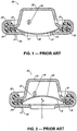
- FIGS. 1 and 2 show cross-sectional views of a prior art reverse buckling device used in a system for interrupting a battery circuit.
- FIGS. 1 and 2 comprise two figures from U.S. Patent No. 5,741,606 ("the '606 patent”), which is directed to an overcharge protection battery vent.
- the device operates to guard against the risk of explosion or the dangerous uncontrolled release of electrolytes in a battery cell device.
- Such devices are sometimes referred to as current interrupt devices, or "CIDs.”
- CIDs current interrupt devices
- the reverse buckling device in its original shape, constitutes part of the electrically conductive pathway of the battery circuit.
- the reverse buckling disk of the '606 patent reverses to interrupt the conducting circuit and block the continued circuit path causing the dangerous over-pressure condition. Where the over-pressure condition becomes too great, the reverse buckling disk fails and ruptures along a predetermined burst pattern to vent the fluid to relieve the pressure.
- FIG. 1 depicts a top portion of a battery terminal contact 21.
- an electrically conducting path traverses conductive tab 26, conductive jacket 25, spherical, domed shaped reverse buckling disk 29, and resistor 22, and terminates at terminal contact 21.
- a dangerous level e.g., due to a dangerous battery malfunction
- fluid pressure in the direction of arrow P eventually causes disk 29 to buckle and reverse.
- disk 29 no longer contacts conductive jacket 25.
- the conducting path is broken, thus removing the cause of the high pressure condition.
- disk 29 is further designed to rupture along scoring lines 27, resulting in the venting of fluid within the battery out of vent holes 28. Because disk 29 provides a spherically shaped dome section and includes a preformed pattern of weakened lines (i.e., scoring 27), it suffers from all of the above-mentioned drawbacks associated with known pressure response members.
- FIG. 3A illustrates a perspective view of a pressure response member 10 according to one embodiment of the present disclosure.
- Pressure response member 10 comprises a concave/convex shaped structure including an flange portion 12 and a flat central portion 14.
- An angled frustum portion 16 between the flange 12 and central portion 14 provides a truncated cone design shape. While FIG. 3A depicts member 10 having a circular shape, other shapes (such as, for example, rectangular) are contemplated.
- pressure response member 10 activates in the direction of arrow P.
- activate and activation refer to the controlled buckling movement or collapse of frustum portion 16, which causes central portion 14 to move.
- FIG. 4 shows a cross-sectional view of a pressure response member 10.
- exterior flange portion 12, flat central portion 14, and the angled frustum portion 16 form a truncated cone shape.
- the embodiment of FIG. 4 depicts frustum angle ⁇ and various design parameters A, B, C, D, and E, which may be selected to provide an activation, or set, pressure P for member 10.
- frustum angle ⁇ may be selected from the range of about 10 to 60 degrees, with a more likely range of about 15 to 35 degrees to achieve a desired activation pressure P.
- structure 16 will collapse and allow central portion 14 to move in direction of arrow P.
- the truncated cone design could be used in applications where the rupture or bursting of the pressure response member is not desired or required.
- activation movement - and not the bursting of the disk - may trigger an indication signal or other control response.
- pressure response member 10 (as illustrated in FIGS. 3A and 4 ) may not require the costly further manufacturing process of forming a burst pattern by means of cutting, scoring, or etching lines of weakness (such as formed by score lines 27 in FIGS. 1 and 2 ).
- the truncated cone shape of FIGS. 3A and 4 may provide the advantage of a more predictable and consistent activation movement than other generally concave/convex shapes.
- a truncated cone's "pie-pan" profile generally symmetrically reverses its orientation upon activation.
- a generally spherically shaped domed structure may only partially collapse or may reverse in an irregular, non-symmetrical fashion.
- a truncated cone design also may provide the advantage of greater resistance to packaging, shipping, handling, and installation damage.
- a damaged pressure response member may exhibit diminished performance-it may activate at a lower pressure than the desired, predetermined set pressure.
- the truncated cone design of FIGS. 3A and 4 resists such damage because it may be thicker (dimension A of FIG. 4 ) than a comparable spherical member with the same set pressure. Stated another way, for a given material thickness and nominal size, the truncated cone shape gives a reversal pressure of about half compared to a traditional shaped disk.
- a 0.25" nominal size truncated cone manufactured from aluminum having a thickness of 0.005" has a response pressure approximately 85 psig, whereas a hemispherical shaped structure of the same nominal size, material, and thickness has a response pressure of approximately 160 psig. Accordingly, the truncated cone design achieves a lower response pressure (i.e., greater sensitivity) for the same thickness of material.
- FIGS. 3A and 4 illustrate a member 10 comprising a symmetrical truncated cone shape
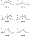
- the present disclosure comprehends irregular cone shapes and irregular dome shapes that also may achieve a reliable response to a predetermined pressure. Examples of these irregular shapes are shown in cross-section in FIGS. 5A (irregular cone) and 5B (irregular dome).
- a pressure response member 10 may include surface or structural modifications to achieve a desired pressure response.
- a symmetrical or irregular (non-symmetrical) cone or an irregular spherical dome of member 10 may include at least one indent to its structure.
- the indent may be formed at or near the apex of the concave/convex shaped structure of member 10.
- an indentation may be formed in a convex surface of the pressure response member-creating an indented cavity 141 in the convex surface while forming a corresponding nipple-shaped protrusion/dimple 142 in the concave surface.
- the indentation may be formed in the concave surface of the pressure response member, creating a cavity 143 in the concave surface and a corresponding nipple-shaped protrusion 144 in the convex surface.
- FIG. 3C Another embodiment of pressure response member 10, shown in FIG. 3C , includes an indentation in the form of a straight line 17 having a midpoint coinciding with the apex of the pressure response member 10.
- the indentation may include two straight lines 17 that intersect at the apex, as shown in FIG. 3D . It is contemplated that changing the size and shape of the structural apex formation can produce wide variations in the pressure at which a disk of given size and material will buckle. For example, a 1" disk made of 0.003" thick material having a small indentation will buckle at a higher pressure than a similar disk with a larger indentation.
- the present disclosure further comprehends providing a central portion 14 that is not flat.
- Exemplary embodiments shown in FIGS. 5E and 5F provide a central portion 14 that may exhibit a concave/convex shape.
- FIGS. 3A and 4 illustrate a central portion 14 that is substantially flat
- FIGS. 5E and 5F provide central portions 14 that exhibit a concave/convex shape
- any other suitable shape of central portion 14 also may be used.
- altering the configuration of the central portion 14 and structural apex formation allows a particular size and thickness pressure response member to be adapted to the particular pressure relief needs of a variety of different commercial applications.
- the response pressure of member 10 is determined by frustum angle ⁇ .
- additional structure may be attached to central portion 14 without substantially altering the response pressure of member 10.
- the additional structure may relate to providing a response control signal upon activation movement of pressure response member 10. Embodiments providing such additional structure are illustrated in FIGS. 6A-12B .
- FIGS. 6B , 7B , 8B , 9B , 10B, 11 B, and 12B depict a relatively flat post-activation shape for member 10; however, the depiction is meant simply to demonstrate a change in displacement distance.
- the "pie pan" profile member 10 generally reverses its position upon activation. This general reversal has a tendency to invert and become a generally mirror image of the initial, pre-activation shape. This final shape is not a perfect mirror image of the initial shape and is often irregular and partially distorted, as evidenced by the undulating pattern of member 10 depicted in FIG. 14B . Therefore, it is to be understood that despite the flat shape of member 10 in FIGS. 6B , 7B , 8B , 9B , 10B , 11 B, and 12B , the actual post-activation shape will exhibit a generally mirrored, albeit irregular, inverted shape (such as illustrated in FIG. 14B ).
- FIGS. 6A-6B depict the use of a pressure response member 10 in a system for closing an electric circuit.
- an open electrical circuit path is present between circuit terminals 40 and 42.
- a pressure response member 10 is positioned relative to terminals 40 and 42 of the illustrated electrical circuit path.
- the central portion 14 of member 10 includes a resilient, electrically conducting spring arch 44.
- the activation movement of member 10 may displace arch 44 into engagement with the terminals 40 and 42, thereby completing an electric circuit as illustrated in FIG. 6B .
- the completed electric circuit may trigger an alarm or any other suitable response to activation of member 10.
- the arch 44 may include structure (e.g., engagement clips, or mating male and female resilient clip members) for mechanically ensuring continued engagement between arch 44 and the circuit terminal after activation of member 10.
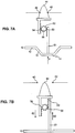
- FIGS. 7A-7B depict the use of a pressure response system for opening an electrical circuit upon activation of member 10.
- the pressure response member 10 is in the inactivated, original position and arch 44 is in position to complete an electrical circuit between terminals 40 and 42.
- Central portion 14 of member 10 supports a projection 51 including engagement teeth 50, which engage teeth 52 of a rotating gear 56.
- teeth 52 of gear 56 engage teeth 54 of a projection 53 that supports arch 44.
- the central portion 14 of member 10 may be displaced such that the teeth 50 move in the direction of arrow 60 to engage teeth 52, resulting in counterclockwise rotation of gear 56, depicted by arrows 58.
- This rotation forces the engagement of teeth 54 with teeth 52, resulting in the movement of arch 44 in the direction of arrow 62, thereby interrupting the electrical circuit between terminals 40 and 44.
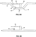
- FIGS. 8A-10B depict alternative arrangements utilizing the circuit components of a photo emitter and photo detector to transmit a control signal in response to the activation of pressure response member 10.
- FIG. 8A depicts a pressure response member 10 incorporating a photo emitter 60 along the central portion 14.
- the upper surface 161 of the frustum includes a photo detector 62 aligned to detect and acknowledge light signal 64.
- a signal is interrupted upon the activation of member 10.
- pressure response member 10 is activated, resulting in displacement of central portion 14.
- This displacement of central portion 14 results in a change in orientation between photo emitter 60 and photo detector 62. More particularly, due to the change in orientation between photo emitter 60 and photo detector 62, photo detector 62 no longer recognizes light signal 64.
- Appropriate response signals may include a toggle switch or other conventional voltage divider used in common logic circuitry to designate one of two conditions.
- FIGS. 9A-10B a responsive signal is transmitted upon the activation of member 10.
- FIGS. 9A-9B illustrate an arrangement whereby photo emitter 60 and photo detector 62 are aligned to generate a responsive acknowledgment signal upon activation of member 10.
- FIGS. 10A-10B illustrate the use of an opaque projection 70 along central portion 14 of member 10, such that upon activation projection 70 disrupts the signal between photo emitter 60 and photo detector 62, thereby resulting in a responsive signal change indicating activation of member 10.
- FIGS. 11A-11B depict the use of a pressure response member 10 in a system for visually indicating activation of the pressure response member.
- the central portion 14 of member 10 in FIG. 11A includes a projection member 82.
- projection 82 In its original, pre-activation position, projection 82 is recessed below an aperture 80 along an indication surface 84.
- the projection is displaced through aperture 80 in indication surface 84. Accordingly, upon the occurrence of a predetermined pressure condition, projection 82 is displaced a predetermined distance D above the indication surface 84, thereby visually indicating that member 10 has activated.
- FIGS. 12A-12B illustrate the use of a pressure response member 10 in a system for closing a fluid path.
- the central portion 14 of member 10 includes a fluid sealing projection 104 aligned with aperture 90 along fluid pipe 100.
- Fluid pipe 100 is completely separate from the fluid and pressure that causes activation of pressure response member 10.
- pressure P activates member 10
- the projection 104 projects through aperture 90 into the fluid pipe 100.
- the final position of sealing projection 104 may block the fluid flow path 102 within pipe 100.
- a pressure response member 10 can be used in a system for interrupting an electrical circuit.
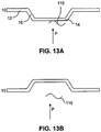
- FIG. 13A depicts the pre-activation arrangement of member 10.
- conductor 110 makes an electric wire connection with a portion of the central section 14 of pressure response member 10.
- a pressure force P acts on the inlet side of member 10.
- FIG. 13B when the magnitude of pressure reaches a predetermined set pressure on the inlet side of member 10, pressure response member 10 activates, displacing and generally inverting pressure response member 10. This activation and inversion may interrupt the connection between conductor 110 and member 10.
- the pressure response member can be arranged to indicate the activation condition through an electric circuit or electric switch utilizing conductor 110.
- pressure response member 10 can be used in a system for interrupting a battery circuit, as shown in FIGS. 14A and 14B .
- FIG. 14A depicts a schematic representation of a battery cell 30.
- the battery cell 30 includes a terminal contact 32, an electrically conducting jacket 34, a pressure response member 10 exhibiting a truncated cone shape, and an insulating gasket 36 disposed between a portion of the electrically conducting jacket 34 and the pressure response member 10.
- the electrical-power-providing components of the battery cell in portion 40 may establish a conducting path at jacket 34. By virtue of contact between jacket 34 and pressure response member 10, an electrical path flows through the system and terminates at terminal contact 32. When a short circuit situation, or any other dangerous, over-pressure situation occurs within the interior portion of battery cell 30, portion 40 experiences increasing pressure. As seen in FIG. 14B , when pressure P reaches a predetermined level, pressure response member 10 activates, thereby breaking the electrically conductive pathway between jacket 34 and pressure response member 10. In the illustrated embodiment, the pressure response member 10 does not include any scoring or line of weakness that causes the member 10 to rupture or burst. Instead, the activation is controlled by virtue of the particular thickness and frustum angle of member 10 (parameters A and ⁇ of FIG. 4 ).
- Typical materials of construction for pressure response member 10 include, but are not limited to, stainless steel, aluminum, nickel or its alloys, carbon, graphite, and plastics. Methods of forming pressure response member 10 include forming or stamping metal coil or sheet material. In addition, manufacturing may include machining of metal, graphite, or plastic material as well as casting, molding, or any combination of the aforementioned manufacturing techniques.
- each of the above described embodiments may be used in combination to provide an alternative response control signal.
- components of each of the different embodiments may be substituted and/or combined in any conceivable manner in order to provide a versatile response system.
- FIG. 15 depicts a flow-chart for a method of responding to an overpressure situation.
- One embodiment includes providing a pressure response member 501 , which includes a flange portion, a central portion, and an angled frustum portion positioned between the flange portion and the central portion.
- the angled frustum portion is configured to activate by buckling and reversing under a predetermined level of pressure - moving from a first configuration to a second configuration.
- the pressure response member is exposed to a pressure source 502, such that the pressure response member responds to a predetermined pressure in the pressure source by taking the second configuration.
- a method for responding to an overpressure situation also may include attaching a conductive arch 503 to the central portion.
- the pressure response member may be positioned relative to an open circuit including a first terminal end and a second terminal end, such that the conductive arch completes the open circuit between the first terminal end and the second terminal end when the pressure response member takes the second configuration.
- a method also may include providing an alarm 504 configured to indicate activation, wherein completing the open circuit between the first terminal end and the second terminal end triggers the alarm. While a method providing an alarm is described, a method providing any other suitable indication or action in response to activation is also comprehended.
- Another embodiment includes providing structure configured to provide visual indication of a response 505.
- structure may include, for example, a projection attached to the central portion, configured to project through an aperture of a visual indication surface after activation.
- a method also may include providing a photo emitter 506 configured to communicate with a photo detector 507.
- the photo detector may be aligned to communicate with the photo emitter before activation, when the pressure response member is in a first configuration.
- the photo detector may be aligned to communicate with the photo emitter after activation, when the pressure response member is in a second configuration.
- a pressure response member activates without rupture or bursting of the pressure response member 10
- there is no abrupt venting of extreme pressure and there is no abrupt change in system pressure that can be documented to test such a pressure response member to determine accuracy and maintain quality control.
- the noise produced by the activation of pressure response member 10 is often insufficient to be detected in a busy workshop environment. Therefore alternative methods and testing mechanisms are useful in testing such a pressure response member to determine accuracy and maintain quality control.
- a method for testing a pressure response member includes providing a pressure response member 400, the pressure response member including a flange portion, a central portion, and an angled frustum portion provided between the flange portion and the central portion.
- An increasing pressure differential may be applied to the pressure response member 402, and a user may record the pressure 410 at which the pressure response member activates.
- Another method for testing a pressure response member may further include placing a pressure response system within a transparent container 401 to allow visual indication of the moment when member activates.
- Further methods for testing a pressure response member may optionally include placing an electrical probe 403 in a position to contact the member only upon activation of the member, or placing a proximity sensor 405 on the outlet side of member 10 in order to measure and record the precise moment of activation.
- exemplary proximity sensors may include, but are not limited to, a dual magnet arrangement, hall effect sensors, or known telemetry devices.
- Another alternative may include placing an audio sensor 407 (e.g., a miniature microphone) with appropriate amplification in relation to the testing chamber and mounting structure in order to precisely detect movement of the pressure response member 10.
- an arthroscopic camera 409 may be appropriately aligned within the testing chamber and mounting structure in order to record movement of the convex/concave structure.
Landscapes
- Chemical & Material Sciences (AREA)
- Electrochemistry (AREA)
- Chemical Kinetics & Catalysis (AREA)
- General Chemical & Material Sciences (AREA)
- Physics & Mathematics (AREA)
- Biochemistry (AREA)
- Fluid Mechanics (AREA)
- General Health & Medical Sciences (AREA)
- General Physics & Mathematics (AREA)
- Health & Medical Sciences (AREA)
- Analytical Chemistry (AREA)
- Pathology (AREA)
- Immunology (AREA)
- Life Sciences & Earth Sciences (AREA)
- Safety Valves (AREA)
- Measuring Fluid Pressure (AREA)
- Control Of Fluid Pressure (AREA)
- Connection Of Batteries Or Terminals (AREA)
- Gas Exhaust Devices For Batteries (AREA)
Description
- This application claims the benefit of
U.S. Provisional Application No. 60/924,306, filed May 8, 2007 - The present disclosure relates generally to pressure response members. Specifically, the present disclosure relates to pressure response members that are buckled, collapsed, or otherwise displaced in response to experiencing a predetermined magnitude of fluid pressure.
- There are many types of systems that process, transport, or utilize a pressurized fluid. To ensure the safety of these types of systems, each such system typically includes a safety device designed to prevent (or at least provide an alarm indication during) the over-pressurization of the system. In an emergency situation, where the fluid in the system reaches an unsafe level, the pressure of the fluid acts on the safety device to create an opening to release fluid from the system. Outside of creating an opening, the safety device may simply provide an alert warning, indicating that a dangerous over-pressure situation is occurring. In devices that actually rupture, or otherwise open to environment, venting fluid to the environment or a safety reservoir through the opening reduces the pressure in the system and prevents another portion of the system from failing due to the high pressure of the fluid.
- Examples of commonly used safety devices include rupture disks and explosion panels. These safety devices can be attached to a pressurized system to expose a certain portion of the device to the pressurized fluid in the system. Often, a portion of the device exposed to the fluid is configured to rupture or tear when the fluid reaches a predetermined pressure. The tearing or rupture of the disk or panel creates an opening through which the pressurized fluid flows to reduce the pressure in the system. This type of safety device is, therefore, self-destructing and must be replaced after each use. Typically, to replace one of these safety devices, some disassembly of the system is needed so that the disk or panel can be properly engaged with the system.
- In addition, where the safety device is designed to rupture or automatically open (i.e., a self-destructing safety device), production and formation often requires precise scoring or otherwise weakening the material of the device in order to ensure opening at a particular location and pressure. For example, rupture disk formation often includes scoring, cutting, etching, or thinning material of the device to outline a predetermined "burst pattern." This precise machining results in added manufacturing time and machinery, thereby increasing manufacturing costs.
- In the field of "reverse buckling" rupture disk pressure relief devices, a concave/convex shaped structure has been used as a means of providing a reliable and reproducible pressure responsive device. Known "reverse buckling" devices are designed such that when the convex side of the structure is exposed to a predetermined overpressure force, the structure "buckles" and inverts causing the convex side to collapse into a concave shape. Moreover, at the predetermined overpressure force, the rupture disk is typically designed not only to invert, but also to open by means of a cutting device located downstream of the disk, or by virtue of a line of weakness produced by scoring, etching, or other means during the manufacturing process.
- Within the broad category of concave/convex shaped structures used for reliable reverse buckling pressure response, there exist many shape subsets, such as, for example, a centered spherical dome, an offset spherical dome, a pyramid shape, and a truncated pyramid shape. The spherical dome shape, frequently used in known reverse buckling devices, suffers from a number of drawbacks. For example, a generally spherically shaped domed structure often only partially collapses during an over-pressure condition. In addition, a spherically shaped, partially domed structure may reverse in an irregular, or uneven, non-symmetrical manner, thereby leading to inconsistent results, particularly for smaller nominal sizes such as below 1" / 25mm diameter. Moreover, during shipping and packaging, the spherical shape is susceptible and often exposed to damage, or mishandling during shipping and packaging that adversely effects the desired response pressure (often leading to rupture or opening at a lower pressure than the set pressure). Finally, the scoring and etching required to form a reproducible burst pattern adds to the overall cost and profit associated with manufacturing.
-
EP 1 508 928 A purports to disclose a battery comprising a spirally wound electrode body in which a cathode and an anode are spirally wound with a separator in between. The battery includes a battery can, a battery cover, a safety valve mechanism, and a positive temperature coefficient ("PTC") device disposed inside the battery cover. Thesafety valve mechanism 15 electrically connected to the battery cover through the PTC device, and when internal pressure in the battery increases to higher than a certain extent due to an internal short circuit or an external application of heat, a disk plate is flipped to as to disconnect the electrical connection between the battery cover and the spirally wound electrode body. -
U.S. Patent No. 5,678,307 A purports to disclose a method of manufacturing rupturable pressure relieving apparatus. As disclosed, an inverting, rupturable, pressure relieving apparatus includes a structure having a wall for containing pressurized fluid and an asymmetrical indentation in the wall. The indentation has a base connecting the indentation to the wall, a protuberant side for contacting the pressurized fluid, a recessed side opposite the protuberant side, and an axis about perpendicular to the base and extending through the center of the indentation at the base. The asymmetry of the indentation creates an inversion initiation face in the indentation having a smaller angle with the base and less resistance to inversion that the remainder of the indentation. -
U.S. Patent No. 4,576,303 A purports to disclose a rupturable pressure relieving fluid container. As disclosed, a substantially frustum-shaped indentation is included in a wall of the container and at least one score is formed on the part of the wall containing the indentation defining a rupture detachable blowout area. The frustum-shaped indentation is of a size with respect to the thickness of the wall containing it whereby when a predetermined fluid pressure is exerted on the wall, the indentation inverts and tears along the line of weakness created by the score thereby opening the portion of the wall corresponding to the blowout area and relieving fluid pressure therethrough. -
GB 1 521 554 A -
U.S. Patent No. 5,741,606 A purports to disclose an overcharge protection battery vent. As disclosed, a cell pressure control system has a two stage control mechanism. In the first stage, increased cell pressure causes a conductive deflection member to bend to a position where it opens an electrical contact and places the cell in open circuit. This prevents current from flowing through the cell and thereby possibly slowing or preventing further increases in cell pressure. The electrical contact relies only upon the pressure of two members (one of which is the deflection member) pushing against one another. If the cell's internal pressure continues to increase even after the pressure contact is broken, the second stage of the pressure control mechanism is activated. Specifically, a pressure rupturable region in the deflection member ruptures to relieve the cell's internal pressure. As disclosed, the pressure rupturable region is a circularly scored region on the conductive deflection member. - There is a need for a pressure response structure that overcomes one or more of the deficiencies above and/or other deficiencies in the art.
- The present invention suggests a device having the features of claim 1 and a method according to the features of
claim 23. The dependent claims relate to advantageous features and embodiments of the invention. - According to one embodiment, a pressure response device includes a flange portion, a central portion having an inlet side and an outlet side, and an angled frustum portion provided between the flange portion and the central portion. The angled frustum portion is configured to activate upon experiencing a predetermined pressure differential causing the movement of the central portion.
- According to another embodiment, a pressure response system comprises a flange portion, a central portion, and an angled frustum portion provided between the flange portion and the central portion. The central portion is substantially flat, and a projection is operably attached to the central portion. The angled frustum portion is configured to activate without rupturing upon experiencing a predetermined pressure differential causing the movement of the central portion, and activation of the frustum portion causes the projection to indicate a pressure response.
- According to another embodiment, a pressure response system includes a pressure response device having a flange portion, a central portion, and an angled frustum portion provided between the flange portion and the central portion. The angled frustum portion is configured to activate upon experiencing a predetermined pressure differential causing the movement of the central portion. A conductor is configured to make an electrical wire connection with the central portion before the angled frustum portion activates, and the electrical wire connection is interrupted when the angled frustum portion activates.
- Further, a battery device is disclosed comprising an exterior contact terminal and a pressure response member positioned within the battery device, the pressure response member having a first configuration and a second configuration, the pressure response member including a central portion surrounded by an angled frustum portion. The pressure response member forms part of an electrical conducting path within the battery device in the first configuration, and upon experiencing a predetermined pressure condition with the battery device, the pressure response member achieves the second configuration and no longer forms part of an electrical conducting path within the battery device.
- According to another embodiment, a method of testing a pressure response system comprises providing a pressure response member including a flange portion, a central portion, and an angled frustum portion between the flange portion and the central portion, applying an increasing pressure differential to one surface of the central portion, and recording the pressure at which the angled frustum portion activates.
- According to another embodiment, a method of responding to an overpressure situation comprises providing a pressure response member including a flange portion, a central portion, and an angled frustum portion between the flange portion and the central portion, wherein the pressure response member has a first configuration and a second configuration. The pressure response member is exposed in the first configuration to a pressure source, such that the pressure response member responds to a predetermined pressure in the pressure source by taking the second configuration.
- Additional objects and advantages of the disclosure will be set forth in part in the description which follows, and in part will be obvious from the description, or may be learned by practice of the disclosure. The objects and advantages of the disclosure will be realized and attained by means of the elements and combinations particularly pointed out in the appended claims.
- It is to be understood that both the foregoing general description and the following detailed description are exemplary and explanatory only and are not restrictive of the invention, as claimed.
- The accompanying drawings, which are incorporated in and constitute a part of this specification, illustrate several embodiments and together with the description, serve to explain the principles of the disclosure.
-
FIG. 1 is a cross-sectional view of a prior art reverse buckling device used in a system for interrupting a battery circuit. -
FIG. 2 is a cross-sectional view of the prior art reverse buckling device ofFIG. 1 after collapse of the reverse buckling device. -
FIGS. 3A is perspective view of a pressure response member, according to an embodiment of the disclosure. -
FIG. 3B is a perspective view of a pressure response member having a line of weakness, according to an embodiment of the disclosure. -
FIG. 3C is a perspective view of a pressure response member having an indentation forming a line, according to an embodiment of the disclosure. -
FIG. 3D is a perspective view of a pressure response member having an indentation forming two lines, according to an embodiment of the disclosure. -
FIG. 4 is a cross-sectional view of the pressure response member ofFIG. 3A . -
FIG. 5A is a cross-sectional view of a pressure response member having an irregular cone shape. -
FIG. 5B is a cross-sectional view of a pressure response member having an irregular dome shape. -
FIGS. 5C-5D depict cross-sectional views of pressure response members having an indentation. -
FIGS. 5E-5F depict cross-sectional views of pressure response members having a concave/convex central portion. -
FIGS. 6A-6B depict the use of a pressure response member in a system for closing an electric circuit. -
FIGS. 7A-7B depict the use of a pressure response member in a system for opening an electric circuit. -
FIGS. 8A-8B depict the use of a pressure response member in another system for opening an electric circuit. -
FIGS. 9A-9B depict the use of a pressure response member in a system for aligning a photo emitter and photo detector. -
FIGS. 10A-10B depict the use of a pressure response member in a system for disrupting the signal between a photo emitter and photo detector. -
FIGS. 11A-11B depict the use of a pressure response member in a system for visually indicating activation of the pressure response member. -
FIGS. 12A-12B depict the use of a pressure response member in a system for closing a fluid path. -
FIGS. 13A-13B depict the use of a pressure response member in a system for effecting electrical interrupt of an electric circuit. -
FIG. 14A is a cross-sectional view of a pressure response member used in a system for interrupting a battery circuit, according to an embodiment of the disclosure. -
FIG. 14B is a cross-sectional view of the system ofFIG. 14A , after activation of the pressure response member, according to an embodiment of the disclosure. -
FIG. 15 is a flow chart depicting a method for testing a pressure response member, according to an embodiment of the disclosure. -
FIG. 16 is a flow chart depicting a method for responding to pressure, according to an embodiment of the disclosure. - Reference will now be made in detail to the present exemplary embodiments, examples of which are illustrated in the accompanying drawings. Wherever possible, the same reference numbers will be used throughout the drawings to refer to the same or like parts. The drawing figures of this application are intended to provide a general understanding of the working elements of the underlying system. Accordingly, unless explicitly stated, the figures do not represent a literal depiction of proportional dimensions or the precise locations for the illustrated inter-related components.
-
FIGS. 1 and 2 show cross-sectional views of a prior art reverse buckling device used in a system for interrupting a battery circuit. In particular,FIGS. 1 and 2 comprise two figures fromU.S. Patent No. 5,741,606 ("the '606 patent"), which is directed to an overcharge protection battery vent. The device operates to guard against the risk of explosion or the dangerous uncontrolled release of electrolytes in a battery cell device. Such devices are sometimes referred to as current interrupt devices, or "CIDs." In normal operation the reverse buckling device, in its original shape, constitutes part of the electrically conductive pathway of the battery circuit. In a short circuit situation, or any other dangerous, over-pressure situation that could lead to catastrophic battery failure due to increasing pressure, the reverse buckling disk of the '606 patent reverses to interrupt the conducting circuit and block the continued circuit path causing the dangerous over-pressure condition. Where the over-pressure condition becomes too great, the reverse buckling disk fails and ruptures along a predetermined burst pattern to vent the fluid to relieve the pressure. -
FIG. 1 depicts a top portion of abattery terminal contact 21. According toFIG. 1 , an electrically conducting path traversesconductive tab 26,conductive jacket 25, spherical, domed shapedreverse buckling disk 29, andresistor 22, and terminates atterminal contact 21. As seen inFIG. 2 , when the pressure within a lower compartment (not shown) of the battery rises to a dangerous level (e.g., due to a dangerous battery malfunction), fluid pressure in the direction of arrow P eventually causesdisk 29 to buckle and reverse. Upon its reversal,disk 29 no longer contacts conductivejacket 25. As a result, the conducting path is broken, thus removing the cause of the high pressure condition. If high pressure nonetheless remains or reaches a certain magnitude,disk 29 is further designed to rupture along scoringlines 27, resulting in the venting of fluid within the battery out of vent holes 28. Becausedisk 29 provides a spherically shaped dome section and includes a preformed pattern of weakened lines (i.e., scoring 27), it suffers from all of the above-mentioned drawbacks associated with known pressure response members. -
FIG. 3A illustrates a perspective view of apressure response member 10 according to one embodiment of the present disclosure.Pressure response member 10 comprises a concave/convex shaped structure including anflange portion 12 and a flatcentral portion 14. Anangled frustum portion 16 between theflange 12 andcentral portion 14 provides a truncated cone design shape. WhileFIG. 3A depictsmember 10 having a circular shape, other shapes (such as, for example, rectangular) are contemplated. - When the underside of the flat
central portion 14 experiences a predetermined set pressure condition,pressure response member 10 activates in the direction of arrow P. For purposes of this specification, the terms "activate" and "activation" refer to the controlled buckling movement or collapse offrustum portion 16, which causescentral portion 14 to move. -
FIG. 4 shows a cross-sectional view of apressure response member 10. According toFIG. 4 ,exterior flange portion 12, flatcentral portion 14, and theangled frustum portion 16 form a truncated cone shape. The embodiment ofFIG. 4 depicts frustum angle θ and various design parameters A, B, C, D, and E, which may be selected to provide an activation, or set, pressure P formember 10. For example, frustum angle θ may be selected from the range of about 10 to 60 degrees, with a more likely range of about 15 to 35 degrees to achieve a desired activation pressure P. Whenmember 10 is subjected to activation pressure P,structure 16 will collapse and allowcentral portion 14 to move in direction of arrow P. - In one embodiment, the truncated cone design could be used in applications where the rupture or bursting of the pressure response member is not desired or required. In such applications, activation movement - and not the bursting of the disk - may trigger an indication signal or other control response. In such an embodiment, pressure response member 10 (as illustrated in
FIGS. 3A and4 ) may not require the costly further manufacturing process of forming a burst pattern by means of cutting, scoring, or etching lines of weakness (such as formed byscore lines 27 inFIGS. 1 and 2 ). - The truncated cone shape of
FIGS. 3A and4 may provide the advantage of a more predictable and consistent activation movement than other generally concave/convex shapes. For example, a truncated cone's "pie-pan" profile generally symmetrically reverses its orientation upon activation. In contrast, a generally spherically shaped domed structure may only partially collapse or may reverse in an irregular, non-symmetrical fashion. - A truncated cone design also may provide the advantage of greater resistance to packaging, shipping, handling, and installation damage. A damaged pressure response member may exhibit diminished performance-it may activate at a lower pressure than the desired, predetermined set pressure. The truncated cone design of
FIGS. 3A and4 resists such damage because it may be thicker (dimension A ofFIG. 4 ) than a comparable spherical member with the same set pressure. Stated another way, for a given material thickness and nominal size, the truncated cone shape gives a reversal pressure of about half compared to a traditional shaped disk. For example, a 0.25" nominal size truncated cone manufactured from aluminum having a thickness of 0.005", has a response pressure approximately 85 psig, whereas a hemispherical shaped structure of the same nominal size, material, and thickness has a response pressure of approximately 160 psig. Accordingly, the truncated cone design achieves a lower response pressure (i.e., greater sensitivity) for the same thickness of material. These material specification differences can result in a thicker disk material that is more resistant to handling damage during shipping and packaging, yet still achieves the same response pressure. - While the embodiments of
FIGS. 3A and4 illustrate amember 10 comprising a symmetrical truncated cone shape, the present disclosure comprehends irregular cone shapes and irregular dome shapes that also may achieve a reliable response to a predetermined pressure. Examples of these irregular shapes are shown in cross-section inFIGS. 5A (irregular cone) and 5B (irregular dome). - Additional embodiments of a
pressure response member 10 may include surface or structural modifications to achieve a desired pressure response. For example, a symmetrical or irregular (non-symmetrical) cone or an irregular spherical dome ofmember 10 may include at least one indent to its structure. The indent may be formed at or near the apex of the concave/convex shaped structure ofmember 10. In one embodiment, shown inFIG. 5C , an indentation may be formed in a convex surface of the pressure response member-creating anindented cavity 141 in the convex surface while forming a corresponding nipple-shaped protrusion/dimple 142 in the concave surface. Alternatively, as shown inFIG. 5D , the indentation may be formed in the concave surface of the pressure response member, creating acavity 143 in the concave surface and a corresponding nipple-shapedprotrusion 144 in the convex surface. - Another embodiment of
pressure response member 10, shown inFIG. 3C , includes an indentation in the form of astraight line 17 having a midpoint coinciding with the apex of thepressure response member 10. In addition, the indentation may include twostraight lines 17 that intersect at the apex, as shown inFIG. 3D . It is contemplated that changing the size and shape of the structural apex formation can produce wide variations in the pressure at which a disk of given size and material will buckle. For example, a 1" disk made of 0.003" thick material having a small indentation will buckle at a higher pressure than a similar disk with a larger indentation. - The present disclosure further comprehends providing a
central portion 14 that is not flat. Exemplary embodiments shown inFIGS. 5E and 5F provide acentral portion 14 that may exhibit a concave/convex shape. AlthoughFIGS. 3A and4 illustrate acentral portion 14 that is substantially flat, andFIGS. 5E and 5F providecentral portions 14 that exhibit a concave/convex shape, any other suitable shape ofcentral portion 14 also may be used. Thus, altering the configuration of thecentral portion 14 and structural apex formation allows a particular size and thickness pressure response member to be adapted to the particular pressure relief needs of a variety of different commercial applications. - For pressure response members of given dimensions A, B, C, D, and E (as shown in
FIG. 4 ) having a flatcentral portion 14, the response pressure ofmember 10 is determined by frustum angle θ. Accordingly, in further embodiments, additional structure may be attached tocentral portion 14 without substantially altering the response pressure ofmember 10. The additional structure may relate to providing a response control signal upon activation movement ofpressure response member 10. Embodiments providing such additional structure are illustrated inFIGS. 6A-12B . - The embodiments shown in
FIGS. 6B ,7B ,8B ,9B ,10B, 11 B, and 12B depict a relatively flat post-activation shape formember 10; however, the depiction is meant simply to demonstrate a change in displacement distance. In practice, the "pie pan"profile member 10 generally reverses its position upon activation. This general reversal has a tendency to invert and become a generally mirror image of the initial, pre-activation shape. This final shape is not a perfect mirror image of the initial shape and is often irregular and partially distorted, as evidenced by the undulating pattern ofmember 10 depicted inFIG. 14B . Therefore, it is to be understood that despite the flat shape ofmember 10 inFIGS. 6B ,7B ,8B ,9B ,10B ,11 B, and 12B , the actual post-activation shape will exhibit a generally mirrored, albeit irregular, inverted shape (such as illustrated inFIG. 14B ). -
FIGS. 6A-6B depict the use of apressure response member 10 in a system for closing an electric circuit. As seen inFIG. 6A , an open electrical circuit path is present betweencircuit terminals pressure response member 10 is positioned relative toterminals central portion 14 ofmember 10 includes a resilient, electrically conductingspring arch 44. Upon experiencing a predetermined set activation pressure P, the activation movement ofmember 10 may displace arch 44 into engagement with theterminals FIG. 6B . The completed electric circuit may trigger an alarm or any other suitable response to activation ofmember 10. In an alternative embodiment (not shown), the arch 44 may include structure (e.g., engagement clips, or mating male and female resilient clip members) for mechanically ensuring continued engagement betweenarch 44 and the circuit terminal after activation ofmember 10. -
FIGS. 7A-7B depict the use of a pressure response system for opening an electrical circuit upon activation ofmember 10. InFIG. 7A , thepressure response member 10 is in the inactivated, original position andarch 44 is in position to complete an electrical circuit betweenterminals Central portion 14 ofmember 10 supports aprojection 51 includingengagement teeth 50, which engageteeth 52 of arotating gear 56. In turn,teeth 52 ofgear 56 engageteeth 54 of a projection 53 that supportsarch 44. - As seen in
FIG. 7B , upon experiencing a predetermined pressure condition P, thecentral portion 14 ofmember 10 may be displaced such that theteeth 50 move in the direction ofarrow 60 to engageteeth 52, resulting in counterclockwise rotation ofgear 56, depicted by arrows 58. This rotation, in turn, forces the engagement ofteeth 54 withteeth 52, resulting in the movement ofarch 44 in the direction ofarrow 62, thereby interrupting the electrical circuit betweenterminals - The embodiments of
FIGS. 8A-10B depict alternative arrangements utilizing the circuit components of a photo emitter and photo detector to transmit a control signal in response to the activation ofpressure response member 10. For example,FIG. 8A depicts apressure response member 10 incorporating aphoto emitter 60 along thecentral portion 14. Theupper surface 161 of the frustum includes aphoto detector 62 aligned to detect and acknowledgelight signal 64. - According to the embodiment of
FIGS. 8A and 8B , a signal is interrupted upon the activation ofmember 10. As seen inFIG. 8B , when the pressure P reaches a predetermined set level,pressure response member 10 is activated, resulting in displacement ofcentral portion 14. This displacement ofcentral portion 14 results in a change in orientation betweenphoto emitter 60 andphoto detector 62. More particularly, due to the change in orientation betweenphoto emitter 60 andphoto detector 62,photo detector 62 no longer recognizeslight signal 64. This loss of signal can be used in any electrical circuit to indicate a desired response signal related to the over-pressure condition. Appropriate response signals may include a toggle switch or other conventional voltage divider used in common logic circuitry to designate one of two conditions. - According to the embodiments of
FIGS. 9A-10B , a responsive signal is transmitted upon the activation ofmember 10. For example,FIGS. 9A-9B illustrate an arrangement wherebyphoto emitter 60 andphoto detector 62 are aligned to generate a responsive acknowledgment signal upon activation ofmember 10. Alternatively,FIGS. 10A-10B illustrate the use of anopaque projection 70 alongcentral portion 14 ofmember 10, such that uponactivation projection 70 disrupts the signal betweenphoto emitter 60 andphoto detector 62, thereby resulting in a responsive signal change indicating activation ofmember 10. -
FIGS. 11A-11B depict the use of apressure response member 10 in a system for visually indicating activation of the pressure response member. Thecentral portion 14 ofmember 10 inFIG. 11A includes aprojection member 82. In its original, pre-activation position,projection 82 is recessed below anaperture 80 along anindication surface 84. Upon activation ofpressure response member 10 due to a predetermined pressure force in the direction of arrow P, the projection is displaced throughaperture 80 inindication surface 84. Accordingly, upon the occurrence of a predetermined pressure condition,projection 82 is displaced a predetermined distance D above theindication surface 84, thereby visually indicating thatmember 10 has activated. -
FIGS. 12A-12B illustrate the use of apressure response member 10 in a system for closing a fluid path. As seen inFIG. 12A , thecentral portion 14 ofmember 10 includes afluid sealing projection 104 aligned withaperture 90 alongfluid pipe 100.Fluid pipe 100 is completely separate from the fluid and pressure that causes activation ofpressure response member 10. When pressure P activatesmember 10, theprojection 104 projects throughaperture 90 into thefluid pipe 100. The final position of sealingprojection 104 may block thefluid flow path 102 withinpipe 100. - In one embodiment, a
pressure response member 10 can be used in a system for interrupting an electrical circuit.FIG. 13A depicts the pre-activation arrangement ofmember 10. On the inlet side ofmember 10,conductor 110 makes an electric wire connection with a portion of thecentral section 14 ofpressure response member 10. During use, a pressure force P acts on the inlet side ofmember 10. As shown inFIG. 13B , when the magnitude of pressure reaches a predetermined set pressure on the inlet side ofmember 10,pressure response member 10 activates, displacing and generally invertingpressure response member 10. This activation and inversion may interrupt the connection betweenconductor 110 andmember 10. In the post-activation configuration, the pressure response member can be arranged to indicate the activation condition through an electric circuit or electricswitch utilizing conductor 110. - In another embodiment,
pressure response member 10 can be used in a system for interrupting a battery circuit, as shown inFIGS. 14A and14B .FIG. 14A depicts a schematic representation of abattery cell 30. Thebattery cell 30 includes aterminal contact 32, an electrically conductingjacket 34, apressure response member 10 exhibiting a truncated cone shape, and an insulatinggasket 36 disposed between a portion of the electrically conductingjacket 34 and thepressure response member 10. - The electrical-power-providing components of the battery cell in
portion 40 may establish a conducting path atjacket 34. By virtue of contact betweenjacket 34 andpressure response member 10, an electrical path flows through the system and terminates atterminal contact 32. When a short circuit situation, or any other dangerous, over-pressure situation occurs within the interior portion ofbattery cell 30,portion 40 experiences increasing pressure. As seen inFIG. 14B , when pressure P reaches a predetermined level,pressure response member 10 activates, thereby breaking the electrically conductive pathway betweenjacket 34 andpressure response member 10. In the illustrated embodiment, thepressure response member 10 does not include any scoring or line of weakness that causes themember 10 to rupture or burst. Instead, the activation is controlled by virtue of the particular thickness and frustum angle of member 10 (parameters A and θ ofFIG. 4 ). - Typical materials of construction for
pressure response member 10 include, but are not limited to, stainless steel, aluminum, nickel or its alloys, carbon, graphite, and plastics. Methods of formingpressure response member 10 include forming or stamping metal coil or sheet material. In addition, manufacturing may include machining of metal, graphite, or plastic material as well as casting, molding, or any combination of the aforementioned manufacturing techniques. - Each of the above described embodiments may be used in combination to provide an alternative response control signal. In addition, components of each of the different embodiments may be substituted and/or combined in any conceivable manner in order to provide a versatile response system.
- Turning to use of the above described embodiments,
FIG. 15 depicts a flow-chart for a method of responding to an overpressure situation. One embodiment includes providing apressure response member 501 , which includes a flange portion, a central portion, and an angled frustum portion positioned between the flange portion and the central portion. The angled frustum portion is configured to activate by buckling and reversing under a predetermined level of pressure - moving from a first configuration to a second configuration. The pressure response member is exposed to apressure source 502, such that the pressure response member responds to a predetermined pressure in the pressure source by taking the second configuration. - In another embodiment, a method for responding to an overpressure situation also may include attaching a
conductive arch 503 to the central portion. The pressure response member may be positioned relative to an open circuit including a first terminal end and a second terminal end, such that the conductive arch completes the open circuit between the first terminal end and the second terminal end when the pressure response member takes the second configuration. A method also may include providing analarm 504 configured to indicate activation, wherein completing the open circuit between the first terminal end and the second terminal end triggers the alarm. While a method providing an alarm is described, a method providing any other suitable indication or action in response to activation is also comprehended. - Another embodiment includes providing structure configured to provide visual indication of a
response 505. Such structure may include, for example, a projection attached to the central portion, configured to project through an aperture of a visual indication surface after activation. - As shown in
FIG. 15 , a method also may include providing aphoto emitter 506 configured to communicate with aphoto detector 507. In one embodiment, the photo detector may be aligned to communicate with the photo emitter before activation, when the pressure response member is in a first configuration. In another embodiment, the photo detector may be aligned to communicate with the photo emitter after activation, when the pressure response member is in a second configuration. - It is a further object of this disclosure to describe alternative methods for testing the pressure response members described herein. When a pressure response member activates without rupture or bursting of the
pressure response member 10, there is no abrupt venting of extreme pressure, and there is no abrupt change in system pressure that can be documented to test such a pressure response member to determine accuracy and maintain quality control. In addition, the noise produced by the activation ofpressure response member 10 is often insufficient to be detected in a busy workshop environment. Therefore alternative methods and testing mechanisms are useful in testing such a pressure response member to determine accuracy and maintain quality control. - As illustrated in
FIG. 16 , a method for testing a pressure response member includes providing apressure response member 400, the pressure response member including a flange portion, a central portion, and an angled frustum portion provided between the flange portion and the central portion. An increasing pressure differential may be applied to thepressure response member 402, and a user may record thepressure 410 at which the pressure response member activates. - Another method for testing a pressure response member may further include placing a pressure response system within a
transparent container 401 to allow visual indication of the moment when member activates. - Further methods for testing a pressure response member may optionally include placing an
electrical probe 403 in a position to contact the member only upon activation of the member, or placing aproximity sensor 405 on the outlet side ofmember 10 in order to measure and record the precise moment of activation. Exemplary proximity sensors may include, but are not limited to, a dual magnet arrangement, hall effect sensors, or known telemetry devices. - Another alternative may include placing an audio sensor 407 (e.g., a miniature microphone) with appropriate amplification in relation to the testing chamber and mounting structure in order to precisely detect movement of the
pressure response member 10. In another alternative, anarthroscopic camera 409 may be appropriately aligned within the testing chamber and mounting structure in order to record movement of the convex/concave structure. - Other embodiments will be apparent to those skilled in the art from consideration of the specification and practice of the disclosure herein. It is intended that the specification and examples be considered as exemplary only, with a true scope of the disclosure being indicated by the following claims.
Claims (25)
- A pressure response device (10) comprising:a flange portion (12);a central portion (14) having an inlet side and an outlet side;an angled frustum portion (16) provided between the flange portion (12) and the central portion (14);characterized in thatthe angled frustum portion (16) is configured to activate without rupturing upon experiencing a predetermined pressure differential causing the movement of the central portion (14); and the pressure response device further comprisesa projection (44, 51, 60, 70, 82, 104) that is operably attached to the central portion (14), wherein the activation of the frustum portion (16) causes the projection (51, 60 ,70, 82, 104) to indicate a pressure response.
- The device of claim 1, wherein upon activation, displacement of the central portion (14) causes the opening of an electric circuit (40, 42, 44, 110).
- The device of claim 1, wherein upon activation, displacement of the central portion (14) causes the closing of an electric circuit (40, 42, 44, 110).
- The device of one of the preceding claims, wherein an angle between the angled frustum portion (16) and a plane defined by the flange portion (12) is between 10 degrees and 60 degrees.
- The device of claim 4, wherein the angle between the angled frustum portion (16) and a plane defined by the flange portion (12) is between 15 degrees and 35 degrees.
- The device of one of the preceding claims, wherein the angled frustum portion (16) is in the shape of a symmetrical truncated cone.
- The device of one of claims 1 to 5, wherein the angled frustum portion (16) is in the shape of an irregular truncated cone.
- The device of one of claims 1 to 5, wherein the angled frustum portion (16) is in the shape of an irregular truncated dome.
- The device of one of claims 1 to 5, wherein the central portion (14) further comprises an indentation (141, 142, 143, 144).
- The device of claim 9, wherein the indentation defines a cavity (141) in the inlet side of the central portion (14) and wherein the indentation (142) defines a nipple in the outlet side of the central portion (14).
- The device of claim 9, wherein the indentation defines a cavity (143) in the outlet side of the central portion (14) and wherein the indentation defines a nipple (144) in the inlet side of the central portion (14).
- The device of claim 9, wherein the indentation defines a line (17), the line having a midpoint coinciding with an apex of the pressure response device.
- The device of claim 9, wherein the indentation defines a first line and a second line, the first line and second line intersecting at an apex of the pressure response device.
- The device of one of the preceding claims, wherein the central portion (14) exhibits a flat shape.
- The device of one of claims 1 to 13, wherein the central portion (14) exhibits a domed shape.
- The device of one of the preceding claims, wherein the pressure response device is constructed from the group of materials consisting of stainless steel, aluminum, nickel and its alloys, carbon, graphite, or plastics.
- The device of one of the preceding claims, wherein the pressure response device is constructed from the group of manufacturing techniques consisting of forming or stamping metal coil, forming or stamping sheet material, machining metal, machining graphite, machining plastic materials, casting, or molding.
- The device of one of claims 1 and 4 to 17, wherein the projection includes a conductive arch (44), the device further comprising:a first circuit terminal (40);a second circuit terminal (42); andwherein the conductive arch (44) is configured to complete a circuit between the first circuit terminal (40) and the second circuit terminal (42).
- The device of claim 18, wherein the conductive arch (44) is configured to complete a circuit between the first circuit terminal (40) and the second circuit terminal (42) after the angled frustum portion activates.
- The device of claim 19, further comprising clips configured to retain the conductive arch (44) between the first circuit terminal (40) and the second circuit terminal (42) after the angled frustum portion (16) activates.
- The device of claim 18, wherein the conductive arch (44) is configured to complete a circuit between the first circuit terminal (40) and the second circuit terminal (42) before the angled frustum portion (16) activates; and
wherein the device is configured to remove the conductive arch (44) and interrupt the circuit between the first circuit terminal (40) and the second terminal (42) when the angled frustum portion (16) activates. - The device of claim 21, further comprising:a toothed member (51, 53) connecting the central portion (14) and the conductive circuit (40, 42, 44);a toothed gear (56);wherein the toothed member (51, 53) is configured to engaged the toothed gear (56) when the angled frustum portion (16) activates; andwherein the conductive arch (44) is removed by the toothed gear (56) when the toothed gear (56) is engaged by the toothed member (51, 53).
- A method of responding to an overpressure situation, comprising:providing a pressure response member including a flange portion (12), a central portion (14), and an angled frustum portion between the flange portion (12) and the central portion, the angled frustum portion (16) being configured to activate without rupturing upon experiencing a predetermined pressure differential causing the movement of the central portion (14);operably attaching a projection (44, 51, 60, 70, 82, 104) to the central portion (14), wherein the pressure response member has a first configuration and a second configuration; exposing the pressure response member in the first configuration to a pressure source, such that the pressure response member responds to the predetermined pressure in the pressure source by taking the second configuration in which the activated frustum portion (16) causes the projection to indicate a pressure response.
- The method of claim 23, comprising:attaching a projection in the form of a conductive arch (44) to the central portion (14);positioning the pressure response member relative to an open circuit including a first terminal end (40) and a second terminal end (42), such that the conductive arch completes the open circuit between the first terminal end and the second terminal end when the pressure response member takes the second configuration.
- The method of claim 24, further comprising:providing an alarm, wherein completing the open circuit between the first terminal end (40) and the second terminal end (42) triggers the alarm.
Applications Claiming Priority (2)
| Application Number | Priority Date | Filing Date | Title |
|---|---|---|---|
| US92430607P | 2007-05-08 | 2007-05-08 | |
| PCT/US2008/005789 WO2008140702A2 (en) | 2007-05-08 | 2008-05-06 | Pressure response membrane |
Publications (3)
| Publication Number | Publication Date |
|---|---|
| EP2149169A2 EP2149169A2 (en) | 2010-02-03 |
| EP2149169B1 true EP2149169B1 (en) | 2017-08-16 |
| EP2149169B8 EP2149169B8 (en) | 2017-10-18 |
Family
ID=39718983
Family Applications (1)
| Application Number | Title | Priority Date | Filing Date |
|---|---|---|---|
| EP08767582.3A Active EP2149169B8 (en) | 2007-05-08 | 2008-05-06 | Pressure response membrane |
Country Status (6)
| Country | Link |
|---|---|
| US (2) | US8525055B2 (en) |
| EP (1) | EP2149169B8 (en) |
| JP (1) | JP5939735B2 (en) |
| KR (1) | KR101387636B1 (en) |
| CN (1) | CN101796665B (en) |
| WO (1) | WO2008140702A2 (en) |
Families Citing this family (20)
| Publication number | Priority date | Publication date | Assignee | Title |
|---|---|---|---|---|
| JP2009543293A (en) | 2006-06-27 | 2009-12-03 | ボストン−パワー,インコーポレイテッド | Integrated current interrupt device for lithium ion cells |
| WO2009002438A1 (en) | 2007-06-22 | 2008-12-31 | Boston-Power, Inc. | Cid retention device for li-ion cell |
| US8642195B2 (en) | 2008-12-19 | 2014-02-04 | Boston-Power, Inc. | Modular CID assembly for a lithium ion battery |
| US8354934B2 (en) | 2010-06-14 | 2013-01-15 | Fike Corporation | Burst indicator |
| US9136071B2 (en) * | 2011-06-10 | 2015-09-15 | International Business Machines Corporation | Overlay for an electrical switch |
| DE112012006312B4 (en) * | 2012-05-02 | 2023-08-31 | Toyota Jidosha Kabushiki Kaisha | Sealed secondary battery |
| WO2014080518A1 (en) * | 2012-11-26 | 2014-05-30 | 日立ビークルエナジー株式会社 | Rectangular secondary battery |
| EP2989359B1 (en) * | 2013-04-25 | 2017-11-08 | BS&B Innovation Limited | Frustum-shaped rupture disk having line of weakness |
| GB2513593B (en) * | 2013-04-30 | 2015-11-04 | Kidde Tech Inc | Pneumatic pressure switch |
| JP6303558B2 (en) | 2014-02-06 | 2018-04-04 | ヤマハ株式会社 | Reaction force generator |
| JP2016091887A (en) * | 2014-11-07 | 2016-05-23 | 株式会社鷺宮製作所 | Method for manufacturing diaphragm with contact, and pressure switch comprising the diaphragm with contact manufactured thereby |
| US10128486B2 (en) * | 2015-03-13 | 2018-11-13 | Purdue Research Foundation | Current interrupt devices, methods thereof, and battery assemblies manufactured therewith |
| JP6638256B2 (en) * | 2015-08-24 | 2020-01-29 | ヤマハ株式会社 | Reaction force generator and keyboard device for electronic musical instrument |
| CN106025148B (en) * | 2016-07-15 | 2019-02-22 | 宁德时代新能源科技股份有限公司 | Explosion-proof structure and power battery comprising same |
| CN110741195A (en) | 2017-03-30 | 2020-01-31 | 唐纳森公司 | Vent with relief valve |
| US11396952B2 (en) * | 2017-10-12 | 2022-07-26 | Bs&B Innovations Limited | Rupture disk |
| WO2019100075A1 (en) * | 2017-11-20 | 2019-05-23 | Johnson Controls Technology Company | Reversal device for li-ion cell overcharge protection |
| JP6696496B2 (en) * | 2017-11-21 | 2020-05-20 | トヨタ自動車株式会社 | Secondary battery |
| FR3097371A1 (en) * | 2019-06-11 | 2020-12-18 | Psa Automobiles Sa | MOTOR VEHICLE BATTERY WITH ELECTRICAL PROPULSION ENERGY, EQUIPPED WITH AN AUDIBLE ALARM DEVICE IN THE EVENT OF THE BATTERY OVERHEATING. |
| GB2585026B (en) | 2019-06-25 | 2023-03-29 | Bae Systems Plc | Overpressure protection system for a magazine |
Family Cites Families (26)
| Publication number | Priority date | Publication date | Assignee | Title |
|---|---|---|---|---|
| US2798130A (en) * | 1953-05-22 | 1957-07-02 | Cutler Hammer Inc | Electric switch devices |
| DE2537510C3 (en) * | 1975-08-22 | 1979-05-31 | Woco Franz-Josef Wolf & Co, 6483 Bad Soden | Two-part overpressure valve |
| JPS5620227U (en) * | 1979-07-24 | 1981-02-23 | ||
| US4476355A (en) * | 1981-11-09 | 1984-10-09 | Grayhill, Inc. | Keyboard assembly |
| DE3314772A1 (en) * | 1983-04-23 | 1984-10-25 | Standard Elektrik Lorenz Ag, 7000 Stuttgart | KEY SWITCH ARRANGEMENT |
| US4576303A (en) * | 1985-02-21 | 1986-03-18 | Bs&B Safety Systems, Inc. | Rupturable pressure relieving fluid containers |
| US4918264A (en) * | 1987-12-26 | 1990-04-17 | Asahi Kogaku Kogyo K.K. | Actuating mechanism and multiposition rubber or membrane switch device |
| US5149923A (en) * | 1991-03-15 | 1992-09-22 | Lucas Duralith Corporation | Backlit tactile keyboard with improved tactile and electrical characteristics |
| CA2067083C (en) * | 1992-01-21 | 1998-06-23 | Stephen P. Farwell | Rupturable pressure relieving apparatus and methods of manufacturing the same |
| US5570803A (en) | 1992-01-21 | 1996-11-05 | Bs&B Safety Systems, Inc. | Rupturable pressure relieving apparatus and methods of manufacturing the same |
| DE9405685U1 (en) * | 1994-04-06 | 1994-05-26 | Filterwerk Mann & Hummel Gmbh, 71638 Ludwigsburg | Differential pressure switch |
| US5413237A (en) * | 1994-06-20 | 1995-05-09 | Bs&B Safety Systems, Inc. | Nonfragmenting rupture disk assemblies and methods |
| US5741606A (en) * | 1995-07-31 | 1998-04-21 | Polystor Corporation | Overcharge protection battery vent |
| US6006938A (en) * | 1997-09-18 | 1999-12-28 | Continental Disc Corporation | Enhanced reverse buckling rupture disc |
| US5878307A (en) * | 1998-02-12 | 1999-03-02 | Nashua Corporation | Toner container having rotary seal |
| US6204635B1 (en) * | 1998-05-22 | 2001-03-20 | Texas Instruments Incorporated | Current interrupt apparatus particularly adapted for use with prismatic electrochemical cells |
| AU4845100A (en) * | 1999-05-13 | 2000-12-05 | Bs & B Safety Systems, Inc. | Rupture disk assembly |
| US6178983B1 (en) * | 1999-05-13 | 2001-01-30 | Bs&B Safety Systems, Inc. | Rupture disk assembly |
| US6855454B2 (en) * | 2001-12-20 | 2005-02-15 | Eveready Battery Company, Inc. | Electrochemical cell having venting current collector and seal assembly |
| JP3791797B2 (en) | 2003-08-21 | 2006-06-28 | ソニー株式会社 | battery |
| JP2005209548A (en) * | 2004-01-23 | 2005-08-04 | Ubukata Industries Co Ltd | Pressure sensor |
| CN2831449Y (en) | 2005-03-14 | 2006-10-25 | 邰永宁 | Safety explosion-proof device for lithium ion cell |
| CN2881974Y (en) * | 2006-01-19 | 2007-03-21 | 东莞新能源电子科技有限公司 | Cylindrical battery protection cover cap |
| US20090053586A1 (en) | 2006-02-17 | 2009-02-26 | Nilar International Ab | Bipolar battery including a pressure sensor |
| WO2009002438A1 (en) * | 2007-06-22 | 2008-12-31 | Boston-Power, Inc. | Cid retention device for li-ion cell |
| JP2009277611A (en) * | 2008-05-19 | 2009-11-26 | Fuji Denshi Kogyo Kk | Contact retention sheet with light guide |
-
2008
- 2008-05-06 EP EP08767582.3A patent/EP2149169B8/en active Active
- 2008-05-06 WO PCT/US2008/005789 patent/WO2008140702A2/en not_active Ceased
- 2008-05-06 KR KR1020097025468A patent/KR101387636B1/en not_active Expired - Fee Related
- 2008-05-06 JP JP2010507429A patent/JP5939735B2/en active Active
- 2008-05-06 US US12/149,691 patent/US8525055B2/en not_active Expired - Fee Related
- 2008-05-06 CN CN200880015100.4A patent/CN101796665B/en not_active Expired - Fee Related
-
2013
- 2013-08-30 US US13/987,768 patent/US10388476B2/en not_active Expired - Fee Related
Non-Patent Citations (1)
| Title |
|---|
| None * |
Also Published As
| Publication number | Publication date |
|---|---|
| WO2008140702A2 (en) | 2008-11-20 |
| KR20100021436A (en) | 2010-02-24 |
| WO2008140702A3 (en) | 2008-12-31 |
| CN101796665B (en) | 2017-10-20 |
| US20150064515A1 (en) | 2015-03-05 |
| US8525055B2 (en) | 2013-09-03 |
| US10388476B2 (en) | 2019-08-20 |
| EP2149169A2 (en) | 2010-02-03 |
| EP2149169B8 (en) | 2017-10-18 |
| US20080289945A1 (en) | 2008-11-27 |
| JP2010527065A (en) | 2010-08-05 |
| CN101796665A (en) | 2010-08-04 |
| JP5939735B2 (en) | 2016-06-22 |
| KR101387636B1 (en) | 2014-04-23 |
Similar Documents
| Publication | Publication Date | Title |
|---|---|---|
| US8525055B2 (en) | Pressure response membrane | |
| EP2989359B1 (en) | Frustum-shaped rupture disk having line of weakness | |
| JP5803553B2 (en) | Sealed battery exhaust plug | |
| US20060121336A1 (en) | Lithium rechargeable battery | |
| US10139005B2 (en) | Pressure relief device integrity sensor | |
| CA2678784A1 (en) | Rupture disk assembly | |
| JPH11213978A (en) | Explosion-proof electrical element | |
| JP2023543955A (en) | pressure relief device | |
| JP6346846B2 (en) | pressure switch | |
| JPH06196140A (en) | Explosion-proof type sealed battery | |
| JP5176427B2 (en) | Sealed storage battery | |
| WO2007036719A1 (en) | Bursting disc assembly | |
| US7011104B2 (en) | Pressure relief device | |
| JP2005235531A (en) | Sealed battery | |
| KR101096061B1 (en) | Bursting Disc Assembly | |
| KR100579378B1 (en) | Lithium secondary battery | |
| JPH10289706A (en) | Sealed battery | |
| JPH08293294A (en) | Sealed battery safety device | |
| JP2002117823A (en) | Safety device for sealed battery and sealed battery using the same | |
| JP4358482B2 (en) | battery | |
| JP6419295B2 (en) | pressure switch | |
| JP2001102038A (en) | Safety device for sealed battery and lead mounting plate in the device | |
| JPH07122254A (en) | Cylindrical alkaline battery | |
| JPS63285860A (en) | Manufacture of battery container used for explosion-proof sealed battery | |
| JPS6386244A (en) | Manufacture of battery container for explosionproof type sealed battery |
Legal Events
| Date | Code | Title | Description |
|---|---|---|---|
| PUAI | Public reference made under article 153(3) epc to a published international application that has entered the european phase |
Free format text: ORIGINAL CODE: 0009012 |
|
| 17P | Request for examination filed |
Effective date: 20091208 |
|
| AK | Designated contracting states |
Kind code of ref document: A2 Designated state(s): AT BE BG CH CY CZ DE DK EE ES FI FR GB GR HR HU IE IS IT LI LT LU LV MC MT NL NO PL PT RO SE SI SK TR |
|
| AX | Request for extension of the european patent |
Extension state: AL BA MK RS |
|
| DAX | Request for extension of the european patent (deleted) | ||
| 17Q | First examination report despatched |
Effective date: 20130227 |
|
| REG | Reference to a national code |
Ref country code: DE Ref legal event code: R079 Ref document number: 602008051659 Country of ref document: DE Free format text: PREVIOUS MAIN CLASS: H01M0002120000 Ipc: H01M0002340000 |
|
| GRAP | Despatch of communication of intention to grant a patent |
Free format text: ORIGINAL CODE: EPIDOSNIGR1 |
|
| RIC1 | Information provided on ipc code assigned before grant |
Ipc: H01M 2/34 20060101AFI20170207BHEP Ipc: H01M 2/12 20060101ALI20170207BHEP |
|
| INTG | Intention to grant announced |
Effective date: 20170227 |
|
| GRAS | Grant fee paid |
Free format text: ORIGINAL CODE: EPIDOSNIGR3 |
|
| GRAA | (expected) grant |
Free format text: ORIGINAL CODE: 0009210 |
|
| AK | Designated contracting states |
Kind code of ref document: B1 Designated state(s): AT BE BG CH CY CZ DE DK EE ES FI FR GB GR HR HU IE IS IT LI LT LU LV MC MT NL NO PL PT RO SE SI SK TR |
|
| REG | Reference to a national code |
Ref country code: GB Ref legal event code: FG4D |
|
| REG | Reference to a national code |
Ref country code: CH Ref legal event code: EP |
|
| RAP2 | Party data changed (patent owner data changed or rights of a patent transferred) |
Owner name: BS&B INNOVATIONS LIMITED |
|
| REG | Reference to a national code |
Ref country code: IE Ref legal event code: FG4D |
|
| REG | Reference to a national code |
Ref country code: AT Ref legal event code: REF Ref document number: 919886 Country of ref document: AT Kind code of ref document: T Effective date: 20170915 |
|
| REG | Reference to a national code |
Ref country code: DE Ref legal event code: R096 Ref document number: 602008051659 Country of ref document: DE |
|
| REG | Reference to a national code |
Ref country code: NL Ref legal event code: MP Effective date: 20170816 |
|
| REG | Reference to a national code |
Ref country code: LT Ref legal event code: MG4D |
|
| REG | Reference to a national code |
Ref country code: AT Ref legal event code: MK05 Ref document number: 919886 Country of ref document: AT Kind code of ref document: T Effective date: 20170816 |
|
| PG25 | Lapsed in a contracting state [announced via postgrant information from national office to epo] |
Ref country code: FI Free format text: LAPSE BECAUSE OF FAILURE TO SUBMIT A TRANSLATION OF THE DESCRIPTION OR TO PAY THE FEE WITHIN THE PRESCRIBED TIME-LIMIT Effective date: 20170816 Ref country code: LT Free format text: LAPSE BECAUSE OF FAILURE TO SUBMIT A TRANSLATION OF THE DESCRIPTION OR TO PAY THE FEE WITHIN THE PRESCRIBED TIME-LIMIT Effective date: 20170816 Ref country code: SE Free format text: LAPSE BECAUSE OF FAILURE TO SUBMIT A TRANSLATION OF THE DESCRIPTION OR TO PAY THE FEE WITHIN THE PRESCRIBED TIME-LIMIT Effective date: 20170816 Ref country code: NL Free format text: LAPSE BECAUSE OF FAILURE TO SUBMIT A TRANSLATION OF THE DESCRIPTION OR TO PAY THE FEE WITHIN THE PRESCRIBED TIME-LIMIT Effective date: 20170816 Ref country code: HR Free format text: LAPSE BECAUSE OF FAILURE TO SUBMIT A TRANSLATION OF THE DESCRIPTION OR TO PAY THE FEE WITHIN THE PRESCRIBED TIME-LIMIT Effective date: 20170816 Ref country code: NO Free format text: LAPSE BECAUSE OF FAILURE TO SUBMIT A TRANSLATION OF THE DESCRIPTION OR TO PAY THE FEE WITHIN THE PRESCRIBED TIME-LIMIT Effective date: 20171116 Ref country code: AT Free format text: LAPSE BECAUSE OF FAILURE TO SUBMIT A TRANSLATION OF THE DESCRIPTION OR TO PAY THE FEE WITHIN THE PRESCRIBED TIME-LIMIT Effective date: 20170816 |
|
| PG25 | Lapsed in a contracting state [announced via postgrant information from national office to epo] |
Ref country code: LV Free format text: LAPSE BECAUSE OF FAILURE TO SUBMIT A TRANSLATION OF THE DESCRIPTION OR TO PAY THE FEE WITHIN THE PRESCRIBED TIME-LIMIT Effective date: 20170816 Ref country code: IS Free format text: LAPSE BECAUSE OF FAILURE TO SUBMIT A TRANSLATION OF THE DESCRIPTION OR TO PAY THE FEE WITHIN THE PRESCRIBED TIME-LIMIT Effective date: 20171216 Ref country code: GR Free format text: LAPSE BECAUSE OF FAILURE TO SUBMIT A TRANSLATION OF THE DESCRIPTION OR TO PAY THE FEE WITHIN THE PRESCRIBED TIME-LIMIT Effective date: 20171117 Ref country code: BG Free format text: LAPSE BECAUSE OF FAILURE TO SUBMIT A TRANSLATION OF THE DESCRIPTION OR TO PAY THE FEE WITHIN THE PRESCRIBED TIME-LIMIT Effective date: 20171116 Ref country code: ES Free format text: LAPSE BECAUSE OF FAILURE TO SUBMIT A TRANSLATION OF THE DESCRIPTION OR TO PAY THE FEE WITHIN THE PRESCRIBED TIME-LIMIT Effective date: 20170816 Ref country code: PL Free format text: LAPSE BECAUSE OF FAILURE TO SUBMIT A TRANSLATION OF THE DESCRIPTION OR TO PAY THE FEE WITHIN THE PRESCRIBED TIME-LIMIT Effective date: 20170816 |
|
| PG25 | Lapsed in a contracting state [announced via postgrant information from national office to epo] |
Ref country code: RO Free format text: LAPSE BECAUSE OF FAILURE TO SUBMIT A TRANSLATION OF THE DESCRIPTION OR TO PAY THE FEE WITHIN THE PRESCRIBED TIME-LIMIT Effective date: 20170816 Ref country code: DK Free format text: LAPSE BECAUSE OF FAILURE TO SUBMIT A TRANSLATION OF THE DESCRIPTION OR TO PAY THE FEE WITHIN THE PRESCRIBED TIME-LIMIT Effective date: 20170816 Ref country code: CZ Free format text: LAPSE BECAUSE OF FAILURE TO SUBMIT A TRANSLATION OF THE DESCRIPTION OR TO PAY THE FEE WITHIN THE PRESCRIBED TIME-LIMIT Effective date: 20170816 |
|
| REG | Reference to a national code |
Ref country code: DE Ref legal event code: R097 Ref document number: 602008051659 Country of ref document: DE |
|
| PG25 | Lapsed in a contracting state [announced via postgrant information from national office to epo] |
Ref country code: EE Free format text: LAPSE BECAUSE OF FAILURE TO SUBMIT A TRANSLATION OF THE DESCRIPTION OR TO PAY THE FEE WITHIN THE PRESCRIBED TIME-LIMIT Effective date: 20170816 Ref country code: SK Free format text: LAPSE BECAUSE OF FAILURE TO SUBMIT A TRANSLATION OF THE DESCRIPTION OR TO PAY THE FEE WITHIN THE PRESCRIBED TIME-LIMIT Effective date: 20170816 |
|
| PLBE | No opposition filed within time limit |
Free format text: ORIGINAL CODE: 0009261 |
|
| STAA | Information on the status of an ep patent application or granted ep patent |
Free format text: STATUS: NO OPPOSITION FILED WITHIN TIME LIMIT |
|
| 26N | No opposition filed |
Effective date: 20180517 |
|
| PG25 | Lapsed in a contracting state [announced via postgrant information from national office to epo] |
Ref country code: SI Free format text: LAPSE BECAUSE OF FAILURE TO SUBMIT A TRANSLATION OF THE DESCRIPTION OR TO PAY THE FEE WITHIN THE PRESCRIBED TIME-LIMIT Effective date: 20170816 |
|
| REG | Reference to a national code |
Ref country code: FR Ref legal event code: PLFP Year of fee payment: 11 |
|
| REG | Reference to a national code |
Ref country code: CH Ref legal event code: PL |
|
| REG | Reference to a national code |
Ref country code: BE Ref legal event code: MM Effective date: 20180531 |
|
| PG25 | Lapsed in a contracting state [announced via postgrant information from national office to epo] |
Ref country code: MC Free format text: LAPSE BECAUSE OF FAILURE TO SUBMIT A TRANSLATION OF THE DESCRIPTION OR TO PAY THE FEE WITHIN THE PRESCRIBED TIME-LIMIT Effective date: 20170816 |
|
| REG | Reference to a national code |
Ref country code: IE Ref legal event code: MM4A |
|
| PG25 | Lapsed in a contracting state [announced via postgrant information from national office to epo] |
Ref country code: CH Free format text: LAPSE BECAUSE OF NON-PAYMENT OF DUE FEES Effective date: 20180531 Ref country code: LI Free format text: LAPSE BECAUSE OF NON-PAYMENT OF DUE FEES Effective date: 20180531 |
|
| PG25 | Lapsed in a contracting state [announced via postgrant information from national office to epo] |
Ref country code: LU Free format text: LAPSE BECAUSE OF NON-PAYMENT OF DUE FEES Effective date: 20180506 |
|
| PG25 | Lapsed in a contracting state [announced via postgrant information from national office to epo] |
Ref country code: IE Free format text: LAPSE BECAUSE OF NON-PAYMENT OF DUE FEES Effective date: 20180506 |
|
| PG25 | Lapsed in a contracting state [announced via postgrant information from national office to epo] |
Ref country code: BE Free format text: LAPSE BECAUSE OF NON-PAYMENT OF DUE FEES Effective date: 20180531 |
|
| PG25 | Lapsed in a contracting state [announced via postgrant information from national office to epo] |
Ref country code: MT Free format text: LAPSE BECAUSE OF NON-PAYMENT OF DUE FEES Effective date: 20180506 |
|
| PG25 | Lapsed in a contracting state [announced via postgrant information from national office to epo] |
Ref country code: TR Free format text: LAPSE BECAUSE OF FAILURE TO SUBMIT A TRANSLATION OF THE DESCRIPTION OR TO PAY THE FEE WITHIN THE PRESCRIBED TIME-LIMIT Effective date: 20170816 |
|
| PG25 | Lapsed in a contracting state [announced via postgrant information from national office to epo] |
Ref country code: HU Free format text: LAPSE BECAUSE OF FAILURE TO SUBMIT A TRANSLATION OF THE DESCRIPTION OR TO PAY THE FEE WITHIN THE PRESCRIBED TIME-LIMIT; INVALID AB INITIO Effective date: 20080506 Ref country code: PT Free format text: LAPSE BECAUSE OF FAILURE TO SUBMIT A TRANSLATION OF THE DESCRIPTION OR TO PAY THE FEE WITHIN THE PRESCRIBED TIME-LIMIT Effective date: 20170816 |
|
| PG25 | Lapsed in a contracting state [announced via postgrant information from national office to epo] |
Ref country code: CY Free format text: LAPSE BECAUSE OF FAILURE TO SUBMIT A TRANSLATION OF THE DESCRIPTION OR TO PAY THE FEE WITHIN THE PRESCRIBED TIME-LIMIT Effective date: 20170816 |
|
| REG | Reference to a national code |
Ref country code: DE Ref legal event code: R079 Ref document number: 602008051659 Country of ref document: DE Free format text: PREVIOUS MAIN CLASS: H01M0002340000 Ipc: H01M0050572000 |
|
| PGFP | Annual fee paid to national office [announced via postgrant information from national office to epo] |
Ref country code: IT Payment date: 20230510 Year of fee payment: 16 |
|
| PGFP | Annual fee paid to national office [announced via postgrant information from national office to epo] |
Ref country code: FR Payment date: 20240509 Year of fee payment: 17 |
|
| PG25 | Lapsed in a contracting state [announced via postgrant information from national office to epo] |
Ref country code: IT Free format text: LAPSE BECAUSE OF NON-PAYMENT OF DUE FEES Effective date: 20240506 |
|
| PGFP | Annual fee paid to national office [announced via postgrant information from national office to epo] |
Ref country code: DE Payment date: 20251107 Year of fee payment: 18 |
|
| PGFP | Annual fee paid to national office [announced via postgrant information from national office to epo] |
Ref country code: GB Payment date: 20251107 Year of fee payment: 18 |
|
| PG25 | Lapsed in a contracting state [announced via postgrant information from national office to epo] |
Ref country code: FR Free format text: LAPSE BECAUSE OF NON-PAYMENT OF DUE FEES Effective date: 20250531 |