EP2149139B1 - Hologram optical device, and compatible optical pickup having the hologram optical device and optical information storage system employing the compatible optical pickup - Google Patents
Hologram optical device, and compatible optical pickup having the hologram optical device and optical information storage system employing the compatible optical pickup Download PDFInfo
- Publication number
- EP2149139B1 EP2149139B1 EP08704903A EP08704903A EP2149139B1 EP 2149139 B1 EP2149139 B1 EP 2149139B1 EP 08704903 A EP08704903 A EP 08704903A EP 08704903 A EP08704903 A EP 08704903A EP 2149139 B1 EP2149139 B1 EP 2149139B1
- Authority
- EP
- European Patent Office
- Prior art keywords
- hologram
- optical
- information storage
- order
- storage medium
- Prior art date
- Legal status (The legal status is an assumption and is not a legal conclusion. Google has not performed a legal analysis and makes no representation as to the accuracy of the status listed.)
- Not-in-force
Links
Images


Classifications
-
- G—PHYSICS
- G11—INFORMATION STORAGE
- G11B—INFORMATION STORAGE BASED ON RELATIVE MOVEMENT BETWEEN RECORD CARRIER AND TRANSDUCER
- G11B7/00—Recording or reproducing by optical means, e.g. recording using a thermal beam of optical radiation by modifying optical properties or the physical structure, reproducing using an optical beam at lower power by sensing optical properties; Record carriers therefor
- G11B7/12—Heads, e.g. forming of the optical beam spot or modulation of the optical beam
- G11B7/135—Means for guiding the beam from the source to the record carrier or from the record carrier to the detector
- G11B7/1353—Diffractive elements, e.g. holograms or gratings
-
- G—PHYSICS
- G11—INFORMATION STORAGE
- G11B—INFORMATION STORAGE BASED ON RELATIVE MOVEMENT BETWEEN RECORD CARRIER AND TRANSDUCER
- G11B7/00—Recording or reproducing by optical means, e.g. recording using a thermal beam of optical radiation by modifying optical properties or the physical structure, reproducing using an optical beam at lower power by sensing optical properties; Record carriers therefor
- G11B2007/0003—Recording, reproducing or erasing systems characterised by the structure or type of the carrier
- G11B2007/0006—Recording, reproducing or erasing systems characterised by the structure or type of the carrier adapted for scanning different types of carrier, e.g. CD & DVD
Definitions
- aspects of the present invention relate to a hologram optical device, a compatible optical pickup having the hologram optical device, and an optical information storage medium system employing the compatible optical pickup; and more particularly, to a hologram optical device for recording and/or reproducing information on or from a plurality of optical information storage media having different thicknesses by using light emitted from a light source, a compatible optical pickup having the hologram optical device, and an optical information storage medium system employing the compatible optical pickup.
- the recording capacity of an optical information storage medium depends on the size of an optical spot of a laser beam focused by an objective lens in an optical information storage medium system that records and/or reproduces data on and/or from the optical disc using the optical spot.
- the size of the optical spot is determined according to the wavelength ⁇ of the laser beam and the numerical aperture (NA) of the objective lens as shown in Equation 1:
- a short wavelength light source such as a blue laser beam
- an objective lens having a high NA are required to reduce the size of the optical spot focused on the optical disc so as to increase the recording density of the optical disc.
- a single side of a BD has a storage capacity of about 25GB.
- the BD standard uses a light source emitting light with a wavelength of about 405 nm and an objective lens having an NA of 0.85.
- the thickness (corresponding to a distance from an optical incidence surface to an information storage surface, i.e., a thickness of a protective layer) of the BD is about 0.1 mm.
- an HD DVD has the storage capacity of about 15GB.
- the HD DVD standard uses a light source emitting light with a wavelength of about 405 nm and an objective lens having an NA of 0.65.
- the thickness of the HD DVD is about 0.6 mm.
- An apparatus is needed that can use two optical information storage media, such as a BD and a HD DVD, in one system.
- two objective lenses suitable for the two optical information storage media are used to allow the two optical information storage media to be compatible with each other.
- two objective lenses and other optical parts related to the two objective lenses must be used.
- the number of optical parts and the production costs are increased.
- Japanese Laid-open Patent No. hei 08-062493 discloses a method of allowing a light source for a DVD to be compatible with a CD-family optical disc by using a hologram lens. In this method, a 0 th -order diffraction beam is transmitted directly, so as to be focused at a focal point. A +1 th -order diffraction beam is transmitted divergently, so as to be focused at a focal point having a different focal distance from the previous focal point.
- the hologram lens diffracts optical beams, which are incident in the form of parallel optical beams, into 0 th -order and +1 th -order diffraction beams.
- the 0 th -order diffraction beam is incident as a divergence-free (convergence-free) beam onto an objective lens and is used to record and/or reproduce information on and/or from a relatively thin optical disc.
- the +1 th -order diffraction beam is diverged and used to record and/or reproduce information on and/or from a relatively thick optical disc.
- An optical spot formed by the 0 th -order diffraction beam is used for recording and/or reproduction with respect to a DVD.
- An optical spot formed by the +1 th -order diffraction beam is used for recording and/or reproduction with respect to a CD.
- the two optical spots are formed on the same optical axis.
- a 0 th -order diffraction beam is used for direct transmission and a +1 th -order diffraction beam is used for divergent transmission so as to perform recording and/or reproduction with respect to a DVD and a CD using a light source for the DVD.
- a hologram optical device diffracts incident beams as 0 th -order and +1 st -order diffraction beams, the amount of the diffraction beams having different orders is not zero.
- the hologram optical device substantially diffracts the incident beam in smaller amounts of different order beams.
- a 0 th -order diffraction beam reflected from an optical disc and then incident onto a hologram lens is diffracted by the hologram lens as a 0 th -order diffraction beam, a +1 st -order diffraction beam, a -1 st -order diffraction beam, or the like.
- the 0 th -order diffraction beam is used to detect a signal reproduced from a DVD.
- the 0 th-order/0 th -order diffraction beam is used as a signal beam to perform reproduction with respect to the DVD.
- a +1 th -order diffraction beam reflected from the optical disc and then incident onto the hologram lens is diffracted by the hologram lens as a 0 th -order diffraction beam, a +1 th -order diffraction beam, a -1 th -order diffraction beam, or the like.
- the +1 th -order diffraction beam is used to detect a signal reproduced from a CD.
- the +1 st -order/1 st -order diffraction beam is used as a signal beam to perform reproduction with respect to the CD.
- a signal beam to perform reproduction with respect to a DVD uses 0 th -order diffraction beam as an incident beam and a 0 th -order diffraction beam generated by being reflected from an optical disc and then incident onto a hologram lens.
- a signal beam to perform reproduction with respect to a CD uses a +1 st -order diffraction beam as an incident beam and a +1 st -order diffraction beam generated by being reflected from an optical disc and then incident onto a hologram lens.
- a 0 th -order/0 th -order diffraction beam may be used as a signal beam for reproduction with respect to the BD
- the 1 st -order/ 1 st -order diffraction beam may be used as a signal beam for reproduction with respect to the HD DVD.
- an incident beam of n-1 th -order diffraction beam/return beam of n+1 th -order diffraction beam and an incident beam of n+1 th -order diffraction beam/return beam of n-1 th -order diffraction beam are also incident onto a photodetector (PD) and thus operate as noise affecting the signal beam.
- the incident beam is a beam diffracted by the hologram optical device and then radiated onto an optical disc.
- the reflected beam is a beam reflected from the optical disc, incident onto and diffracted by the hologram optical device, and further proceeding toward the PD.
- FIGS. 1A and 1B show optical paths of beams of different diffraction orders diffracted by a hologram optical element (HOE).
- FIG. 1A shows optical paths of diffracted beams of different diffraction orders in the case of a BD.
- FIG. 1B shows optical paths of diffracted beams in the case of an HD DVD.
- OL denotes an objective lens.
- a parallel beam collimated by a light source is incident onto the HOE.
- a 0 th -order diffraction beam incident from the HOE is reflected from a BD and then is incident onto the HOE through the 0 th -order diffraction beam path.
- the 0 th -order diffraction beam advances as a parallel beam after passing through the HOE.
- a 1 st -order diffraction beam incident from the HOE is reflected from the BD and then is incident onto the HOE through a -1 st -order diffraction beam path.
- the -1 st -order diffraction beam is incident onto the HOE and then advances as a parallel beam after passing through the HOE.
- a -1 st -order diffraction beam incident from the HOE is reflected from the BD and then is incident onto the HOE through a 1 st -order diffraction beam path. This beam advances as a parallel beam after passing through the HOE.
- the 0 th -order/0 th -order diffraction beam, the -1 st -order/1 st -order diffraction beam, and the 1 st -order/-1 st -order diffraction beam advance through the same optical path after passing through the HOE.
- the 0 th -order/0 th -order diffraction beam is used as a signal beam for reproduction with respect to the BD
- the -1 st -order/1 st -order diffraction beam and the 1 st -order/-1 st -order diffraction beam operate as noise and interfere with the reproduction of data stored on the BD.
- the noise is created because a size of a spot formed on a PD by the -1 st -order/1 st -order diffraction beam and the 1 st -order/-1 st -order diffraction beam with respect to the BD and the 0 th -order/2 nd -order diffraction beam and the 2 nd -order/0 th -order diffraction beam with respect to the HD DVD is a similar level according to a size of a spot formed by signal beam.
- the noise is a main factor in the deterioration of a reproduced signal.
- the efficiency of diffraction beams generating noise needs to be reduced to reduce noise and to increase the qualities of signals reproduced from the BD and the HD DVD.
- a BD DL RE (hereinafter referred to as a BD DL)
- noise due to a +1 st -order/-2 nd -order diffraction beam, a -2 nd -order/+1 st -order diffraction beam or a -2 nd -order/0 th -order diffraction beam, and a 0 th -order/-2 nd -order diffraction beam reflected from a surface of the BD.
- a BD DL there may be flowed noise due to diffraction beams of different diffraction orders and noise due to beams reflected from the surface of the BD DL.
- FIGS. 2A and 2B show optical paths of beams of different diffraction orders diffracted by a HOE when reproduction is performed with respect to a BD DL.
- FIG. 2A shows optical paths of diffraction beams when reproduction is performed with respect to a layer L1 of a BD DL.
- FIG. 2B shows optical paths of diffraction beams when reproduction is performed with respect to a layer L0 of the BD DL.
- a layer L1 is positioned at a distance of 75 ⁇ m from a surface of the BD DL
- the layer L0 is positioned at a distance of 25 ⁇ m from the layer L1 .
- a +1 ⁇ st> -order diffraction beam incident from the HOE is reflected from a surface of the BD DL and then is incident onto the HOE through a -2 ⁇ nd> -order diffraction beam path.
- a -2 ⁇ nd> -order diffraction beam is incident onto the HOE and then advances as a parallel beam.
- a -2 ⁇ nd> -order diffraction beam incident from the HOE is reflected from the surface of the BD DL and then is incident onto the HOE through a +1 ⁇ st> -order diffraction beam path.
- a +1 ⁇ st> -order diffraction beam is incident onto the HOE and then advances as a parallel beam.
- the +1 ⁇ st> -order/-2 ⁇ nd> -order diffraction beam and the -2 ⁇ nd> - order/+1 ⁇ st> -order diffraction beam advance along the same optical path as the 0th -order/0th -order diffraction beam after passing through the HOE.
- the +1 ⁇ st> -order/-2 ⁇ nd> -order diffraction beam and the -2 ⁇ nd> -order/+1 ⁇ st> -order diffraction beam reflected from the surface of the BD DL is flowed as noise when reproduction is performed with respect to the layer L1.
- the efficiency of diffraction beams generating noise must be reduced in order to improve the qualities of signals reproduced from a BD and a HD DVD.
- Noise reflected from a surface of a BD DL must also be reduced in order to improve the quality of a signal reproduced from the BD DL when reproduction is performed with respect to the BD DL.
- EP-A- 1 003 161 describes an hologram optical element for generating different diffraction orders for a tracking error signal.
- US 2005/0018560 describes a HD-DVD/BD compatible pick-up with a hologram element having concentrically formed four step patterns.
- US 5 777 973 A describes a diffraction grating for an optical pick-up.
- aspects of the present invention provide a hologram optical device capable of reducing an inflow of noise generated by unnecessary diffraction beams when an incident beam of 0th -order/return beam of 0th -order diffraction beam is used as a signal beam for a Blu-ray disc (BD) and an incident beam of 1 ⁇ st> -order/return beam of 1 ⁇ st> -order diffraction beam is used as a signal beam for a high definition digital versatile disc (HD DVD), so as to improve a signal-to-noise ratio (SNR) of an information reproduction signal, a compatible optical pickup having the hologram optical device, and an optical information storage system employing the compatible optical pickup.
- BD Blu-ray disc
- HD DVD high definition digital versatile disc
- the hologram optical device when an incident 0 th -order/returned 0 th -order diffraction beam as a signal beam for a BD and an incident 1 st -order/ returned 1 st -order diffraction beam as a signal beam for a HD DVD is used, the hologram optical device can reduce an inflow of noise generated by unnecessary diffraction beams.
- a compatible optical pickup and an optical information storage medium system capable of improving signal characteristics of the BD and the HD DVD can be realized.
- FIGS. 1A and 1B illustrate optical paths of beams of different diffraction orders diffracted by a hologram optical element (HOE) in the case of a Blu-ray disc (BD) and a high definition digital versatile disc (HD DVD);
- HOE hologram optical element
- FIGS. 2A and 2B illustrate optical paths of beams of different diffraction orders diffracted by a HOE when reproduction is performed with respect to layers L1 and L0 of a BD DL;
- FIG. 3 schematically illustrates a compatible optical pickup employing a hologram optical device according to an embodiment of the present invention
- FIG. 4 illustrates a hologram optical device according to an embodiment of the present invention
- FIG. 5 is an enlarged cross-sectional view illustrating hologram patterns formed in a first area of the hologram optical device illustrated in FIG. 4 , according to an embodiment of the present invention
- FIG. 6 is a cross-sectional view illustrating hologram patterns of a general diffraction device (hologram optical device);
- FIG. 7 illustrates a conventional hologram optical device disclosed in Japanese Laid-open Patent No. 1992-212730 , corresponding to the general hologram optical device illustrated in FIG. 6 ;
- FIG. 8 is a graph illustrating variations in ⁇ - 1 ⁇ ⁇ 1 ⁇ 0 ⁇ ⁇ 0 , ⁇ 2 ⁇ ⁇ 0 ⁇ 1 ⁇ ⁇ 1 , and ⁇ - 2 ⁇ ⁇ 1 ⁇ 0 ⁇ ⁇ 0 ⁇ ⁇ - 2 ⁇ ⁇ 0 ⁇ 0 ⁇ ⁇ 0 with respect to variations in ⁇ 2 ;
- FIG. 12 illustrates hologram patterns of a hologram optical device, according to an embodiment of the present invention.
- FIG. 13 schematically illustrates an optical information storage medium system employing a compatible optical pickup according to an embodiment of the present invention.
- FIG. 3 shows a compatible optical pickup 10 employing a hologram optical device according to an embodiment of the present invention.
- the compatible optical pickup 10 may use both a first optical information storage medium 1a of a first standard and a second optical information storage medium 1b of a second standard.
- the compatible optical pickup 10 includes a light source 11, an objective lens 30, an optical path changer 15, a photodiode (PD) 19, and a hologram optical device 20.
- the light source 11 emits beam having predetermined wavelength.
- the compatible optical pickup 10 may include additional and/or different components. Similarly, the functionality of two or more of the above components may be combined into a single unit.
- the objective lens 30 focuses an incident beam onto an optical information storage medium 1.
- the optical path changer 15 is disposed on an optical path between the light source 11 and the objective lens 30 to change the advancing path of the incident beam.
- the PD 19 receives the incident beam, which is reflected from the optical information storage medium 1, via the objective lens 30 and the optical path changer 15.
- the hologram optical device 20 diffracts the beams incident from the light source 11 as a 0 th -order diffraction beam that is directly transmitted and a 1 st -order diffraction beam that is divergently transmitted.
- the first and second optical information media 1a and 1b correspond to standards defining optical discs having different thicknesses and using a beam having the same wavelength.
- the first optical information storage medium 1a may correspond to the Blur-ray disc (BD) standard.
- the second optical information storage medium 1b may correspond to the high definition digital versatile disc (HD DVD) standard.
- a thickness of the first optical information storage medium 1a may be about 0.1mm.
- a thickness of the second optical information storage medium may be about 0.6mm.
- the first optical information storage medium 1a of the first standard and the second optical information storage medium 1b of the second standard are exemplarily described as a BD and a HD DVD, respectively.
- the first and second optical information storage media according to other aspects of the invention may also conform to different standards and have thicknesses corresponding to these different standards.
- the light source 11 emits a beam of a wavelength commonly used for the BD 1a and the HD DVD 1b.
- the light source 11 may emit a blue beam having a wavelength between 400 nm and 420 nm, such as about 405 nm.
- the light source 11 may be a semiconductor laser that emits a blue laser beam.
- the objective lens 30 focuses the incident beam onto the optical information storage medium 1.
- the objective lens 30 may be also provided to be suitable for the BD 1a and thus may have a first numerical aperture (NA), such as an NA of 0.85.
- NA numerical aperture
- a 0 th -order diffraction beam passes straight through first and second areas 21 and 23 of the hologram optical device 20, which will be described later with respect to FIG. 4 , and then is focused onto the BD 1a by the objective lens 30.
- a 1 st -order diffraction beam is diffracted in the first area 21 of the hologram optical device 20 and then focused onto the HD DVD 1b by the objective lens 30.
- a collimating lens 13 may be further included on the optical path between the light source 11 and the objective lens 30 so as to collimate divergent beams emitted from the light source 11 as parallel beam. As shown in FIG. 3 , the collimating lens 13 is disposed between the optical path changer 15 and the hologram optical device 20.
- a detection lens 18 may be further included on an optical path between the optical path changer 15 and the PD 19 so as to focus the beam reflected from the optical information storage medium 1 with an optical spot having an appropriate size onto the PD 19.
- the detection lens 18 may be an astigmatic lens so as to detect a focus error signal using an astigmatic method.
- the optical path changer 15 may include a general beam splitter. Alternatively, the optical path changer 15 may include a polarization beam splitter (PBS) and a quarter wave plate.
- PBS polarization beam splitter
- the compatible optical pickup 10 may further include a grating (not shown) to detect a tracking servo signal using a 3-beam method or differential push pull (DPP).
- the grating may be disposed on an optical path between the light source 11 and the optical path changer 15 so as to split a beam incident from the light source 11 into three beams, i.e., a main beam and two sub beams.
- the PD 19 may include a main light-receiving area receiving the main beam and first and second sub light-receiving areas respectively receiving the two sub beams.
- the main light-receiving area may have four light-receiving areas.
- the sub light-receiving areas may have two light-receiving areas.
- the tracking servo signal may be detected using DPP or the 3-beam method.
- the compatible optical pickup 10 detects the tracking servo signal using the 3-beam method
- the first and second light-receiving areas may have a single light-receiving area.
- the hologram optical device 20 diffracts the beam incident from the light source as the 0 th -order and 1 st -order diffraction beams.
- the 0 th -order diffraction beam is used to perform recording and/or reproduction with respect to the BD 1a.
- the 1 st -order diffraction beam is used to perform recording and/or reproduction with respect to the HD DVD 1b.
- the hologram optical device 20 is fixed by a support member 25 so as to keep a predetermined distance from the objective lens 30.
- FIG. 4 illustrates the hologram optical device 20 according to an embodiment of the present invention.
- a hologram 22 is formed in the hologram optical device 20 to reduce an inflow of noise generated by other diffraction beams.
- a cross-section of a hologram pattern of a period 1P of the hologram 22 is formed in a 4-step stairway shape, and at least one of first through fourth steps of the 4-step stairway shape has a different width from the other steps.
- the hologram optical device 20 includes the first area 21 in which the hologram 22 having the 4-step stairway shape is formed.
- the hologram 22 in the first area 21 is formed so as to transmit a 0 th -order diffraction beam directly and to diverge a 1 st -order diffraction beam.
- the hologram 22 in the first area 21 may be formed so that the diffraction efficiency of the 0 th -order diffraction beam is approximate to that of the 1 st -order diffraction beam.
- the approximation between the diffraction efficiencies includes a possibility that the diffraction efficiencies are the same.
- the hologram 22 in the first area 21 is formed in a step-shaped hologram pattern on the same axis so as to operate as a hologram lens that diverges the 1 st -order diffraction beam.
- a size of the first area 21 may be determined to have a second NA suitable for the HD DVD 1b, e.g., a NA of 0.65, when the first area 21 is combined with the objective lens 30.
- the hologram 22 formed in the first area 21 will be described in more detail later.
- the hologram optical device 20 further includes a second area 23 that is formed outside the first area 21 and in which holograms 24 are formed to diffract incident beam as an incident 0 th -order diffraction beam and a convergent 1 st -order diffraction beam.
- the hologram 24 in the second area 23 is formed in a step-shaped hologram pattern on the same axis so as to operate as a hologram lens that converges the 1 st -order diffraction beam.
- the holograms 24 are formed in the second area 23 in a step shape symmetrical to a step shape of the hologram 22 formed in the first area 21 so as to prevent a +1 st -order diffraction beam from being focused onto the HD DVD 1b.
- the 0 th -order diffraction beam diffracted by the holograms 24 in the second area 23 is used as an effective beam for the BD 1a, while the 1 st -order diffraction beam is not focused onto an information storage surface of the HD DVD 1b and thus is not used as an effective beam for the BD.
- a size of the second area 23 may be determined by the first NA suitable for the BD 1a, e.g., the NA of 0.85.
- the holograms 24 in the second area 23 may be formed so that the diffraction efficiency of the 0 th -order diffraction beam is approximate to or greater than that of the 1 st -order diffraction beam.
- the approximation between the diffraction efficiencies includes a possibility that the diffraction efficiencies are the same.
- the holograms 24 in the second area 23 may be substantially formed in the same step shape as the hologram 22 in the first area 21. However, in the invention the step shape of the holograms 24 is symmetrical to that of the hologram 22.
- the hologram 22 and 24 are respectively formed in the first and second areas 21 and 23 of the hologram optical device 20.
- Other hologram optical devices may have a structure in which the hologram 22 is formed in the first area 21 but the hologram 24 is not formed in the second area 23.
- FIG. 5 is an enlarged cross-sectional view showing hologram patterns formed in the first area 21 of the hologram optical device 20 of FIG. 4 , according to an embodiment of the present invention.
- a hologram pattern is also formed in the second area 23 of the hologram optical device 20.
- a cross-section of a hologram pattern of the hologram optical device 20 with a period 1P may have a 4-step stairway shape. At least one of first, second, third, and fourth steps S1 , S2 , S3 , and S4 of the 4-step stairway shape has a different width from the other steps.
- a conventional hologram optical device disclosed in Japanese Laid-open Patent No. 1992-212730 is now compared with the hologram optical device 20.
- the widths of steps are the same, but the heights of step differences of the steps are different so as to change phases of the steps.
- the incident beam is mainly diffracted as 0 th -order and 1 st -order diffraction beams.
- the widths of steps are adjusted to mainly diffract incident beams as 0 th -order and 1 st -order diffraction beams and suppress the diffraction efficiencies of -1 st -order, 2 nd -order, and -2 nd -order diffraction beams.
- an inflow of noise generated by unnecessary diffraction beams is reduced.
- the widths of the first and fourth steps S1 and S4 are equal to each another, and the widths of the second and third steps S2 and S3 are be equal to each other.
- the total width of the hologram pattern with the period 1P having the 4-step stairway shape is T
- the widths of the first, second, third, and fourth steps S1 , S2 , S3 , and S4 are W01 , W12 , W23 , and W34 , respectively.
- the widths W01 and W34 of the first and fourth steps S1 and S4 may each be '1/4T - aT
- the widths W12 and W23 of the second and third steps S2 and S3 may each be '1/4T + aT', where 'a' denotes a number having an absolute value smaller than '1' and is expressed with duty variations.
- the hologram pattern of the hologram optical device 20 is formed so as to satisfy conditions that the widths W01 and W34 of the first and fourth steps S1 and S4 are equal to each other and each equal to or greater than 0.16T and less than 0.25 T, and the widths W12 and W23 of the second and third steps S2 and S3 are equal to each other and each equal to '0.5T-W01.'
- a step difference between the first and second steps S1 and S2 is d12
- a step difference between the second and third steps S2 and S3 is d23
- a step difference between the third and fourth steps S3 and S4 is d34
- phase variations of beam determined by the step differences d12 , d23 , and d34 are ⁇ 12 , ⁇ 23 , ⁇ 34, respectively.
- the 4-step stairway shape may be formed so that at least a portion of the phase variations is different from the others.
- the hologram optical device 20 uses the incident 0 th -order diffraction beam/return beam of 0 th -order diffraction beam as the signal beam for the BD 1a and the incident 1 st -order/reflected 1 st -order diffraction beam as the signal beam for the HD DVD 1b as described above, a ratio of optical power of a noise beam to optical power of the signal beam may be minimized.
- a ratio of optical power of a noise beam to optical power of a signal beam should be minimized in order to improve signal characteristics of a BD and a HD DVD. Since the BD uses a 0 th -order diffraction beam as a signal beam and the HD DVD uses a 1 st -order diffraction beam as a signal beam, the diffraction efficiencies of the 0 th -order and 1 st -order diffraction beams should be maximized in order to minimize a ratio of optical power of a noise beam to optical power of the signal beams, and thus improve the signal characteristics of the BD and the HD DVD.
- the hologram optical device 20 should satisfy Equation 2:
- ⁇ 0 , ⁇ 1 , ⁇ -1 , ⁇ 2 , and ⁇ -2 denote 0 th -order, 1 st -order, - 1 st -order, 2 nd -order, and -2 nd -order diffraction efficiencies, respectively.
- a general diffraction device having a pattern of a period with a 4-step stairway shape, as shown in FIG. 6 i.e., a hologram optical device 20'
- a refractive index of a medium of the hologram optical device 20' is n 1 .
- a refractive index of a medium (an air gap) around the medium is n 0 .
- d1 denotes a step difference between fourth and third steps S4' and S3'
- d2 denotes a step difference from the fourth step S4' to a second step S2'
- d3 denotes a step different from the fourth step S4' to a first step S1' .
- a width of the first step S1' is ⁇ T
- a width of a sum of the first and second steps S1' and S2' is ⁇ T
- a width of a sum of the first, second, and third steps S1' , S2' , and S3' is ⁇ T .
- transmissivity T m of each diffraction order and diffraction efficiency ⁇ m of the each diffraction order corresponding to the square of the transmissivity T m are expressed as in Equations 3 and 4, respectively:
- T m 1 T ⁇ 0 ⁇ ⁇ T e 2 ⁇ ⁇ im T ⁇ x d x + 1 T ⁇ ⁇ ⁇ T ⁇ ⁇ T e 2 ⁇ ⁇ im T ⁇ x ⁇ e 2 ⁇ ⁇ i ⁇ n 1 - n 0 ⁇ d 1 ⁇ ⁇ x d x + 1 T ⁇ ⁇ ⁇ T ⁇ ⁇ T e 2 ⁇ ⁇ im T ⁇ x ⁇ e 2 ⁇ ⁇ i ⁇ n 1 - n 0 ⁇ d 2 ⁇ x d x + 1 T ⁇ ⁇ ⁇ T T e 2 ⁇ ⁇ im T ⁇ x ⁇ e 2 ⁇ ⁇ i ⁇ n 1 - n 0 ⁇ d 3 ⁇ ⁇ x d x
- a conventional hologram optical device 20 As shown in FIG. 7 , the phase variations determined by the step differences of hologram pattern are changed to be the diffraction efficiency of each diffraction order.
- Such a conventional hologram optical device 20" is disclosed in Japanese Laid-open Patent No. 1992-212730 .
- a total width of a pattern of a period of the hologram optical device 20' is T .
- First, second, third, and fourth steps S1' , S2' , S3' , and S4' of a 4-step stairway of the conventional hologram optical device 20" each have a width of 0.25T.
- a phase variation ⁇ 12 determined by a step difference between the first and second steps S1' and S2' is equal to a phase variation ⁇ 34 determined by a step difference between the third and fourth steps S3' and S4' .
- the diffraction efficiency is expressed as in Equation 5. When only a depth of the hologram optical device 20" is changed, the 2 nd -order diffraction efficiency is equal to the -2 nd -order diffraction efficiency.
- ⁇ 1 is a sum of the phase variation ⁇ 12 determined by the step difference between the first and second steps S1' and S2' and a phase variation ⁇ 23 determined by a step difference between the second and third steps S2' and S3'
- ⁇ 2 corresponds to the phase variation ⁇ 34 determined by the step difference between the third and fourth steps S3' and S4' .
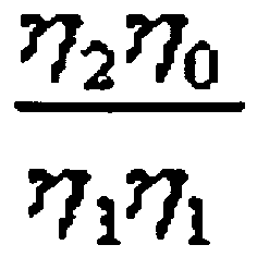
- ⁇ - 1 ⁇ ⁇ 1 ⁇ 0 ⁇ ⁇ 0 and ⁇ 2 ⁇ ⁇ 0 ⁇ 1 ⁇ ⁇ 1 respectively denote ratios of optical power of a -1 st -order/1 st -order diffraction beam (noise beam) to optical power of a signal beam and optical power of a 2 nd -order/0 th -order diffraction beam (noise beam) to optical power of the signal beam.
- the conditions of the phase variation ⁇ 2 can be deduced from Equation 6.
- FIG. 8 is a graph showing variations in ⁇ - 1 ⁇ ⁇ 1 ⁇ 0 ⁇ ⁇ 0 ⁇ 2 ⁇ ⁇ 0 ⁇ 1 ⁇ ⁇ 1 , and ⁇ - 2 ⁇ ⁇ 1 ⁇ 0 ⁇ ⁇ 0 ⁇ ⁇ - 2 ⁇ ⁇ 0 ⁇ 0 ⁇ ⁇ 0 with respect to the phase variation ⁇ 2 .
- ⁇ - 2 ⁇ ⁇ 1 ⁇ 0 ⁇ ⁇ 0 ⁇ ⁇ - 2 ⁇ ⁇ 0 ⁇ 0 ⁇ ⁇ 0 denotes a ratio of optical power of a +1 st -order/-2 nd -order or -2 nd -order/0 th -order diffraction beam to optical power of a signal beam, wherein the +1 st -order/-2 nd -order or -2 nd -order/0 th -order diffraction beam is reflected from a surface of a BD having a rewritable dual layer structure when reproduction is performed with respect to the BD.
- ⁇ 0 ⁇ 1
- ⁇ - 1 ⁇ ⁇ 1 ⁇ 0 ⁇ ⁇ 0 and ⁇ 2 ⁇ ⁇ 0 ⁇ 1 ⁇ ⁇ 1 may each be reduced to be lower than 0.1.
- the phase variation ⁇ 1 is about 92.26°.
- phase variations ⁇ 12 , ⁇ 23, and ⁇ 34 may be obtained from Equation 6 and have values of 54.05, 38.21, and 54.05, respectively, when ⁇ - 1 ⁇ ⁇ 1 ⁇ 0 ⁇ ⁇ 0 , ⁇ 2 ⁇ ⁇ 0 ⁇ 1 ⁇ ⁇ 1 , and ⁇ - 2 ⁇ ⁇ 1 ⁇ 0 ⁇ ⁇ 0 ⁇ ⁇ - 2 ⁇ ⁇ 0 ⁇ 0 ⁇ ⁇ 0 are minimized.
- the hologram optical device 20 changes the widths of steps of hologram pattern in order to reduce the proportions of ⁇ - 1 ⁇ ⁇ 1 ⁇ 0 ⁇ ⁇ 0 , ⁇ 2 ⁇ ⁇ 0 ⁇ 1 ⁇ ⁇ 1 , and ⁇ - 2 ⁇ ⁇ 1 ⁇ 0 ⁇ ⁇ 0 ⁇ ⁇ - 2 ⁇ ⁇ 0 ⁇ 0 ⁇ ⁇ 0 ⁇ ⁇ 0
- the heights of steps are the same and the widths of the steps are different from one another so as to minimize ⁇ - 1 ⁇ ⁇ 1 ⁇ 0 ⁇ ⁇ 0 , ⁇ 2 ⁇ ⁇ 0 ⁇ 1 ⁇ ⁇ 1 , and ⁇ - 2 ⁇ ⁇ 1 ⁇ 0 ⁇ ⁇ 0 ⁇ ⁇ - 2 ⁇ ⁇ 0 ⁇ 0 ⁇ ⁇ 0
- the ratios ⁇ - 1 ⁇ ⁇ 1 ⁇ 0 ⁇ ⁇ 0 , ⁇ 2 ⁇ ⁇ 0 ⁇ 1 ⁇ ⁇ 1 , and ⁇ - 2 ⁇ ⁇ 1 ⁇ 0 ⁇ 0 ⁇ ⁇ - 2 ⁇ ⁇ 0 ⁇ 0 ⁇ ⁇ 0 in the hologram optical device 20 can be numerically calculated from Equations 3 and 4 above.
- widths W01 and W34 when the widths W01 and W34 are equal, and the widths W12 and W23 are equal, the widths W01 and W34 are each changed by '-a,' and the widths W12 and W23 are each changed by '+a.
- 'a' denotes a duty variation.
- the efficiencies and the ratios are obtained with respect to the duty variations when a total width T is fixed.
- the ratios of optical powers of noise beams to optical powers of signal beams i.e., the ratios ⁇ - 1 ⁇ ⁇ 1 ⁇ 0 ⁇ ⁇ 0 , ⁇ 2 ⁇ ⁇ 0 ⁇ 1 ⁇ ⁇ 1 , and ⁇ - 2 ⁇ ⁇ 1 ⁇ 0 ⁇ ⁇ 0 ⁇ ⁇ - 2 ⁇ ⁇ 0 ⁇ 0 ⁇ ⁇ 0 ⁇ ⁇ 0 , may be all minimized.
- the ratios ⁇ - 1 ⁇ ⁇ 1 ⁇ 0 ⁇ ⁇ 0 and ⁇ 2 ⁇ ⁇ 0 ⁇ 1 ⁇ ⁇ 1 are each about 10% and thus almost equal to those of the prior art described with reference to FIG. 8 .
- the ratio ⁇ - 2 ⁇ ⁇ 1 ⁇ 0 ⁇ ⁇ 0 ⁇ ⁇ - 2 ⁇ ⁇ 0 ⁇ 0 ⁇ ⁇ 0 is about 4.2% and thus can be reduced by about 2.4 times that of the prior art.
- Table 1 shows the diffraction efficiencies and ratios ⁇ - 1 ⁇ ⁇ 1 ⁇ 0 ⁇ ⁇ 0 , ⁇ 2 ⁇ ⁇ 0 ⁇ 1 ⁇ ⁇ 1 , and ⁇ - 2 ⁇ ⁇ 1 ⁇ 0 ⁇ ⁇ 0 ⁇ ⁇ - 2 ⁇ ⁇ 0 ⁇ 0 ⁇ ⁇ 0 when the hologram optical device 20, the conventional hologram optical device 20", and the general hologram optical device 20' are used.
- the ratio ⁇ 2 ⁇ ⁇ 0 ⁇ 1 ⁇ ⁇ 1 indicating a ratio of noise to a signal beam of a HD DVD is 11% in the case of the present invention but 10.5% in the case of the prior art.
- the ratio ⁇ 2 ⁇ ⁇ 0 ⁇ 1 ⁇ ⁇ 1 hardly differs in the cases of the present invention and the prior art.
- the ratios ⁇ - 1 ⁇ ⁇ 1 ⁇ 0 ⁇ ⁇ 0 and ⁇ - 2 ⁇ ⁇ 1 ⁇ 0 ⁇ ⁇ 0 ⁇ ⁇ - 2 ⁇ ⁇ 0 ⁇ 0 ⁇ ⁇ 0 ⁇ ⁇ 0 indicating ratios of noise to signal beam of a BD is 11% and 4.2%, respectively, and the sum of the ratios is 15.2%.
- the ratios ⁇ - 1 ⁇ ⁇ 1 ⁇ 0 ⁇ ⁇ 0 and ⁇ - 2 ⁇ ⁇ 1 ⁇ 0 ⁇ ⁇ 0 ⁇ ⁇ - 2 ⁇ ⁇ 0 ⁇ 0 ⁇ ⁇ 0 ⁇ ⁇ 0 are 10.5% and 10.5%, respectively, and the sum of the ratios is 21%.
- the widths of steps of a 4-step stairway of each hologram pattern of a hologram optical device according to aspects of the present invention can be adjusted to greatly improve a ratio of noise to a signal beam of the BD compared to the prior art.
- FIG. 12 shows a hologram pattern of the hologram optical device 20 used to obtain the results of Table 1, according to an embodiment of the present invention.
- the hologram optical device 20 may be formed so that a duty variation a is 0.3T, and the heights of the steps each have a phase difference of 0.28 ⁇ .
- the use efficiency of an incident 0 th -order/returned 0 th -order diffraction beam used as a signal beam for the first information storage medium of the first standard, i.e., the BD 1a, is increased.
- An incident 1 st -order/returned 1 st -order diffraction beam used as a signal beam for the second information storage medium of the second standard, i.e., the HD DVD 1b is increased.
- the use efficiencies of unnecessary diffraction beams e.g., -1 st -order, -2 nd -order, and 2 nd -order diffraction beams are not increased. As a result, a signal-to-noise ratio (SNR) of an information signal can be improved.
- SNR signal-to-noise ratio
- the hologram optical device 20 has a 4-step stairway, the step differences of the four steps of the 4-step stairway are equal, the first and fourth steps have the same width of 0.22T, and the second and third steps have the same width of 0.28T so as to reduce noise beams.
- the present invention is not limited thereto. It will be understood by those of ordinary skill in the art that various changes in form and details may be made therein without departing from the spirit and scope of the present invention as defined by the following claims.
- the hologram optical device 20 may constitute a phase type hologram lens.
- recording and/or reproduction can be performed with respect to a plurality of optical information storage media, e.g., a BD and a HD DVD, using one light source.
- FIG. 13 schematically illustrates an optical information storage medium system employing the compatible optical pickup 10, according to an embodiment of the present invention.
- the optical information storage medium system includes a spindle motor 312, the compatible optical pickup 10, a driver 307, and a controller 309.
- the spindle motor 312 rotates an optical information storage medium 1.
- the compatible optical pickup 10 is moveably installed in a radius direction of the optical information storage medium 1 so as to record and/or reproduce information on and/or from the optical information storage medium 1.
- the driver 307 drives the spindle motor 312 and the compatible optical pickup 10.
- the controller 309 controls focus, tracking, and/or tilt servos of the compatible optical pickup 10.
- Reference numerals 352 and 353 respectively denote a turntable and a clamp that chucks the optical information storage medium 1.
- the optical information storage medium system may be incorporated into a stand-alone recording and/or reproducing apparatus or may be incorporated into another device, such as a computer or video game console.
- a beam reflected from the optical information storage medium 1 is detected by the PD 19 of the compatible optical pickup 10, photoelectrically transformed into an electrical signal, and input to the controller 309 through the driver 307.
- the driver 307 controls a rotation speed of the spindle motor 312, amplifies an input signal, and drives the compatible optical pickup 10.
- the controller 309 transmits focus, tracking, and/or tilt servo commands, which are controlled based on the signal input from the driver 307, to the driver 307 so as to realize focusing, tracking, and/or tilt operations.
- the optical information storage medium system employing the compatible optical pickup 10 of the present invention may use both a BD and an HD DVD.
Landscapes
- Physics & Mathematics (AREA)
- Optics & Photonics (AREA)
- Optical Head (AREA)
Abstract
Description
- Aspects of the present invention relate to a hologram optical device, a compatible optical pickup having the hologram optical device, and an optical information storage medium system employing the compatible optical pickup; and more particularly, to a hologram optical device for recording and/or reproducing information on or from a plurality of optical information storage media having different thicknesses by using light emitted from a light source, a compatible optical pickup having the hologram optical device, and an optical information storage medium system employing the compatible optical pickup.
- The recording capacity of an optical information storage medium, such as an optical disc, depends on the size of an optical spot of a laser beam focused by an objective lens in an optical information storage medium system that records and/or reproduces data on and/or from the optical disc using the optical spot. The size of the optical spot is determined according to the wavelength λ of the laser beam and the numerical aperture (NA) of the objective lens as shown in Equation 1:
-

- Accordingly, a short wavelength light source, such as a blue laser beam, and an objective lens having a high NA are required to reduce the size of the optical spot focused on the optical disc so as to increase the recording density of the optical disc.
- According to the Blu-ray disc (BD) standard, a single side of a BD has a storage capacity of about 25GB. The BD standard uses a light source emitting light with a wavelength of about 405 nm and an objective lens having an NA of 0.85. The thickness (corresponding to a distance from an optical incidence surface to an information storage surface, i.e., a thickness of a protective layer) of the BD is about 0.1 mm. According to the high definition digital versatile disc (HD DVD) standard, an HD DVD has the storage capacity of about 15GB. The HD DVD standard uses a light source emitting light with a wavelength of about 405 nm and an objective lens having an NA of 0.65. The thickness of the HD DVD is about 0.6 mm.
- An apparatus is needed that can use two optical information storage media, such as a BD and a HD DVD, in one system. In one attempt to address this need, two objective lenses suitable for the two optical information storage media are used to allow the two optical information storage media to be compatible with each other. In this case, however, two objective lenses and other optical parts related to the two objective lenses must be used. Thus, the number of optical parts and the production costs are increased. In addition, it is difficult to fit an optical axis between the two objective lenses.
- In order to solve these problems, a method of using only one objective lens and reducing spherical aberration using a hologram optical device may be considered. Japanese Laid-open Patent No.
hei 08-062493 - In the above disclosure, the hologram lens diffracts optical beams, which are incident in the form of parallel optical beams, into 0th-order and +1th-order diffraction beams. The 0th-order diffraction beam is incident as a divergence-free (convergence-free) beam onto an objective lens and is used to record and/or reproduce information on and/or from a relatively thin optical disc. The +1th-order diffraction beam is diverged and used to record and/or reproduce information on and/or from a relatively thick optical disc. An optical spot formed by the 0th-order diffraction beam is used for recording and/or reproduction with respect to a DVD. An optical spot formed by the +1th-order diffraction beam is used for recording and/or reproduction with respect to a CD. The two optical spots are formed on the same optical axis.
- As described above, a 0th-order diffraction beam is used for direct transmission and a +1th-order diffraction beam is used for divergent transmission so as to perform recording and/or reproduction with respect to a DVD and a CD using a light source for the DVD. However, although a hologram optical device diffracts incident beams as 0th-order and +1st-order diffraction beams, the amount of the diffraction beams having different orders is not zero. The hologram optical device substantially diffracts the incident beam in smaller amounts of different order beams.
- Accordingly, a 0th-order diffraction beam reflected from an optical disc and then incident onto a hologram lens is diffracted by the hologram lens as a 0th-order diffraction beam, a +1st-order diffraction beam, a -1st-order diffraction beam, or the like. The 0th-order diffraction beam is used to detect a signal reproduced from a DVD. The 0 th-order/0th-order diffraction beam is used as a signal beam to perform reproduction with respect to the DVD.
- Similarly, a +1th-order diffraction beam reflected from the optical disc and then incident onto the hologram lens is diffracted by the hologram lens as a 0th-order diffraction beam, a +1th-order diffraction beam, a -1th-order diffraction beam, or the like. The +1th-order diffraction beam is used to detect a signal reproduced from a CD. The +1st-order/1st-order diffraction beam is used as a signal beam to perform reproduction with respect to the CD.
- A signal beam to perform reproduction with respect to a DVD uses 0th-order diffraction beam as an incident beam and a 0th-order diffraction beam generated by being reflected from an optical disc and then incident onto a hologram lens. A signal beam to perform reproduction with respect to a CD uses a +1st-order diffraction beam as an incident beam and a +1st-order diffraction beam generated by being reflected from an optical disc and then incident onto a hologram lens.
- If these diffraction beams are used to perform reproduction with respect to a BD and a HD DVD, a 0th-order/0th-order diffraction beam may be used as a signal beam for reproduction with respect to the BD, and the 1st-order/ 1st-order diffraction beam may be used as a signal beam for reproduction with respect to the HD DVD. However, when an incident nth-order diffraction beam/return beam of nth-order diffraction beam is used as a signal beam by a hologram optical device, an incident beam of n-1th-order diffraction beam/return beam of n+1th-order diffraction beam and an incident beam of n+1th-order diffraction beam/return beam of n-1th-order diffraction beam are also incident onto a photodetector (PD) and thus operate as noise affecting the signal beam. The incident beam is a beam diffracted by the hologram optical device and then radiated onto an optical disc. The reflected beam is a beam reflected from the optical disc, incident onto and diffracted by the hologram optical device, and further proceeding toward the PD.
-
FIGS. 1A and1B show optical paths of beams of different diffraction orders diffracted by a hologram optical element (HOE).FIG. 1A shows optical paths of diffracted beams of different diffraction orders in the case of a BD.FIG. 1B shows optical paths of diffracted beams in the case of an HD DVD. InFIGS. 1A and1B , OL denotes an objective lens. - As shown in
FIG. 1A , a parallel beam collimated by a light source is incident onto the HOE. A 0th-order diffraction beam incident from the HOE is reflected from a BD and then is incident onto the HOE through the 0th-order diffraction beam path. The 0th-order diffraction beam advances as a parallel beam after passing through the HOE. A 1st-order diffraction beam incident from the HOE is reflected from the BD and then is incident onto the HOE through a -1st-order diffraction beam path. The -1st-order diffraction beam is incident onto the HOE and then advances as a parallel beam after passing through the HOE. A -1st-order diffraction beam incident from the HOE is reflected from the BD and then is incident onto the HOE through a 1st-order diffraction beam path. This beam advances as a parallel beam after passing through the HOE. - Accordingly, when the BD is used, the 0th-order/0th-order diffraction beam, the -1st-order/1st-order diffraction beam, and the 1st-order/-1st-order diffraction beam advance through the same optical path after passing through the HOE. Thus, when the 0th-order/0th-order diffraction beam is used as a signal beam for reproduction with respect to the BD, the -1st-order/1st-order diffraction beam and the 1st-order/-1st-order diffraction beam operate as noise and interfere with the reproduction of data stored on the BD.
- Similarly, as shown in
FIG. 1B , when a 1st-order/1st-order diffraction beam is used as a signal beam for reproduction with respect to the HD DVD, a 0th-order/2nd-order diffraction beam and a 2nd-order/0th-order diffraction beam operate as noise. - The noise is created because a size of a spot formed on a PD by the -1st-order/1st-order diffraction beam and the 1st-order/-1st-order diffraction beam with respect to the BD and the 0th-order/2nd-order diffraction beam and the 2nd-order/0th-order diffraction beam with respect to the HD DVD is a similar level according to a size of a spot formed by signal beam. The noise is a main factor in the deterioration of a reproduced signal. The efficiency of diffraction beams generating noise needs to be reduced to reduce noise and to increase the qualities of signals reproduced from the BD and the HD DVD.
- When reproduction is performed with respect to a BD having a rewritable dual layer structure, i.e., a BD DL RE (hereinafter referred to as a BD DL), there is flowed noise due to a +1st-order/-2nd-order diffraction beam, a -2nd-order/+1st-order diffraction beam or a -2nd-order/0th-order diffraction beam, and a 0th-order/-2nd-order diffraction beam reflected from a surface of the BD. When reproduction is performed with respect to a BD DL, there may be flowed noise due to diffraction beams of different diffraction orders and noise due to beams reflected from the surface of the BD DL.
-
FIGS. 2A and2B show optical paths of beams of different diffraction orders diffracted by a HOE when reproduction is performed with respect to a BD DL.FIG. 2A shows optical paths of diffraction beams when reproduction is performed with respect to a layer L1 of a BD DL.FIG. 2B shows optical paths of diffraction beams when reproduction is performed with respect to a layer L0 of the BD DL. InFIGS. 2A and2B , a layer L1 is positioned at a distance of 75 µm from a surface of the BD DL, and the layer L0 is positioned at a distance of 25 µm from the layer L1. - As shown in
FIG. 2A , when an optical spot is formed by a 0th-order diffraction beam at a distance of about 150µm from an optical spot formed by a +1st-order diffraction beam in the BD DL, noise due to a +1st-order/-2nd-order diffraction beam and a -2nd-order/+1st-order diffraction beam reflected from a surface of the BD DL is flowed during reproduction with respect to the layer L1. - A +1 <st> -order diffraction beam incident from the HOE is reflected from a surface of the BD DL and then is incident onto the HOE through a -2<nd> -order diffraction beam path. Thus, a -2<nd> -order diffraction beam is incident onto the HOE and then advances as a parallel beam. A -2<nd> -order diffraction beam incident from the HOE is reflected from the surface of the BD DL and then is incident onto the HOE through a +1 <st> -order diffraction beam path. Thus, a +1<st> -order diffraction beam is incident onto the HOE and then advances as a parallel beam.
- Accordingly, the +1<st> -order/-2<nd> -order diffraction beam and the -2<nd> - order/+1 <st> -order diffraction beam advance along the same optical path as the 0th -order/0th -order diffraction beam after passing through the HOE. Thus, the +1 <st> -order/-2<nd> -order diffraction beam and the -2<nd> -order/+1<st> -order diffraction beam reflected from the surface of the BD DL is flowed as noise when reproduction is performed with respect to the layer L1.
- As shown in
FIG. 2B , when an optical spot is formed by a 0th -order diffraction beam at a distance of about 100 [mu]m from an optical spot formed by a 1<st> -order diffraction beam in the BD DL, noise due to a 0th -order/-2<nd> -order diffraction beam and a -2<nd> -order/0th -order diffraction beam reflected from a surface of the BD DL is flowed during reproduction with respect to the layer L0, resulting in the deterioration of the quality of a reproduced signal. - Therefore, the efficiency of diffraction beams generating noise must be reduced in order to improve the qualities of signals reproduced from a BD and a HD DVD. Noise reflected from a surface of a BD DL must also be reduced in order to improve the quality of a signal reproduced from the BD DL when reproduction is performed with respect to the BD DL.
-
EP-A- 1 003 161 describes an hologram optical element for generating different diffraction orders for a tracking error signal.US 2005/0018560 describes a HD-DVD/BD compatible pick-up with a hologram element having concentrically formed four step patterns.US 5 400 311 AUS 5 777 973 A - The invention is defined by the appended claims.
- Aspects of the present invention provide a hologram optical device capable of reducing an inflow of noise generated by unnecessary diffraction beams when an incident beam of 0th -order/return beam of 0th -order diffraction beam is used as a signal beam for a Blu-ray disc (BD) and an incident beam of 1<st> -order/return beam of 1 <st> -order diffraction beam is used as a signal beam for a high definition digital versatile disc (HD DVD), so as to improve a signal-to-noise ratio (SNR) of an information reproduction signal, a compatible optical pickup having the hologram optical device, and an optical information storage system employing the compatible optical pickup.
- Additional aspects and/or advantages of the invention will be set forth in part in the description which follows and, in part, will be obvious from the description, or may be learned by practice of the invention.
- As described above, according to a hologram optical device according to aspects of the present invention, when an incident 0th-order/returned 0th-order diffraction beam as a signal beam for a BD and an incident 1st-order/ returned 1st-order diffraction beam as a signal beam for a HD DVD is used, the hologram optical device can reduce an inflow of noise generated by unnecessary diffraction beams. Thus, when the hologram optical device is used, a compatible optical pickup and an optical information storage medium system capable of improving signal characteristics of the BD and the HD DVD can be realized.
- These and/or other aspects and advantages of the invention will become apparent and more readily appreciated from the following description of the embodiments, taken in conjunction with the accompanying drawings of which:
-
FIGS. 1A and1B illustrate optical paths of beams of different diffraction orders diffracted by a hologram optical element (HOE) in the case of a Blu-ray disc (BD) and a high definition digital versatile disc (HD DVD); -
FIGS. 2A and2B illustrate optical paths of beams of different diffraction orders diffracted by a HOE when reproduction is performed with respect to layers L1 and L0 of a BD DL; -
FIG. 3 schematically illustrates a compatible optical pickup employing a hologram optical device according to an embodiment of the present invention; -
FIG. 4 illustrates a hologram optical device according to an embodiment of the present invention; -
FIG. 5 is an enlarged cross-sectional view illustrating hologram patterns formed in a first area of the hologram optical device illustrated inFIG. 4 , according to an embodiment of the present invention; -
FIG. 6 is a cross-sectional view illustrating hologram patterns of a general diffraction device (hologram optical device); -
FIG. 7 illustrates a conventional hologram optical device disclosed in Japanese Laid-open Patent No.1992-212730 FIG. 6 ; -
FIG. 8 is a graph illustrating variations in

and
with respect to variations in Φ2; -
FIG. 9 is a graph illustrating variations in efficiencies of 0th-order, 1st-order, -1st-order, 2nd-order, and -2nd-order diffraction beams according to Φ1 when Φ2=54.05°; -
FIG. 10 is a graph illustrating efficiencies of -1st-order, -2nd-order, and 2nd-order diffraction beams with respect to duty variations when η0=η1; -
FIG. 11 is a graph illustrating ratios of

and
with respect to duty variations when η0=η1; -
FIG. 12 illustrates hologram patterns of a hologram optical device, according to an embodiment of the present invention; and -
FIG. 13 schematically illustrates an optical information storage medium system employing a compatible optical pickup according to an embodiment of the present invention. -
FIG. 3 shows a compatibleoptical pickup 10 employing a hologram optical device according to an embodiment of the present invention. The compatibleoptical pickup 10 may use both a first optical information storage medium 1a of a first standard and a second opticalinformation storage medium 1b of a second standard. The compatibleoptical pickup 10 includes alight source 11, anobjective lens 30, anoptical path changer 15, a photodiode (PD) 19, and a hologramoptical device 20. Thelight source 11 emits beam having predetermined wavelength. According to other aspects of the present invention, the compatibleoptical pickup 10 may include additional and/or different components. Similarly, the functionality of two or more of the above components may be combined into a single unit. - The
objective lens 30 focuses an incident beam onto an opticalinformation storage medium 1. Theoptical path changer 15 is disposed on an optical path between thelight source 11 and theobjective lens 30 to change the advancing path of the incident beam. ThePD 19 receives the incident beam, which is reflected from the opticalinformation storage medium 1, via theobjective lens 30 and theoptical path changer 15. The hologramoptical device 20 diffracts the beams incident from thelight source 11 as a 0 th-order diffraction beam that is directly transmitted and a 1st-order diffraction beam that is divergently transmitted. - The first and second
optical information media 1a and 1b correspond to standards defining optical discs having different thicknesses and using a beam having the same wavelength. The first optical information storage medium 1a may correspond to the Blur-ray disc (BD) standard. The second opticalinformation storage medium 1b may correspond to the high definition digital versatile disc (HD DVD) standard. A thickness of the first optical information storage medium 1a may be about 0.1mm. A thickness of the second optical information storage medium may be about 0.6mm. The first optical information storage medium 1a of the first standard and the second opticalinformation storage medium 1b of the second standard are exemplarily described as a BD and a HD DVD, respectively. However, the first and second optical information storage media according to other aspects of the invention may also conform to different standards and have thicknesses corresponding to these different standards. - The
light source 11 emits a beam of a wavelength commonly used for the BD 1a and theHD DVD 1b. For example, thelight source 11 may emit a blue beam having a wavelength between 400 nm and 420 nm, such as about 405 nm. Thelight source 11 may be a semiconductor laser that emits a blue laser beam. - The
objective lens 30 focuses the incident beam onto the opticalinformation storage medium 1. Theobjective lens 30 may be also provided to be suitable for the BD 1a and thus may have a first numerical aperture (NA), such as an NA of 0.85. - When the BD 1a is used, a 0th-order diffraction beam passes straight through first and
second areas optical device 20, which will be described later with respect toFIG. 4 , and then is focused onto the BD 1a by theobjective lens 30. When theHD DVD 1b is used, a 1st-order diffraction beam is diffracted in thefirst area 21 of the hologramoptical device 20 and then focused onto theHD DVD 1b by theobjective lens 30. - A collimating
lens 13 may be further included on the optical path between thelight source 11 and theobjective lens 30 so as to collimate divergent beams emitted from thelight source 11 as parallel beam. As shown inFIG. 3 , the collimatinglens 13 is disposed between theoptical path changer 15 and the hologramoptical device 20. Adetection lens 18 may be further included on an optical path between theoptical path changer 15 and thePD 19 so as to focus the beam reflected from the opticalinformation storage medium 1 with an optical spot having an appropriate size onto thePD 19. Thedetection lens 18 may be an astigmatic lens so as to detect a focus error signal using an astigmatic method. Theoptical path changer 15 may include a general beam splitter. Alternatively, theoptical path changer 15 may include a polarization beam splitter (PBS) and a quarter wave plate. - The compatible
optical pickup 10 may further include a grating (not shown) to detect a tracking servo signal using a 3-beam method or differential push pull (DPP). The grating may be disposed on an optical path between thelight source 11 and theoptical path changer 15 so as to split a beam incident from thelight source 11 into three beams, i.e., a main beam and two sub beams. In this case, thePD 19 may include a main light-receiving area receiving the main beam and first and second sub light-receiving areas respectively receiving the two sub beams. For example, the main light-receiving area may have four light-receiving areas. The sub light-receiving areas may have two light-receiving areas. In this case, the tracking servo signal may be detected using DPP or the 3-beam method. When the compatibleoptical pickup 10 detects the tracking servo signal using the 3-beam method, the first and second light-receiving areas may have a single light-receiving area. The detailed structures of the grating and thePD 19 used for detecting the tracking servo signal when the 3-beam method or DPP is used are well known in the art, and thus their illustrations will be omitted. - The hologram
optical device 20 diffracts the beam incident from the light source as the 0th-order and 1st-order diffraction beams. The 0th-order diffraction beam is used to perform recording and/or reproduction with respect to the BD 1a. The 1st-order diffraction beam is used to perform recording and/or reproduction with respect to theHD DVD 1b. The hologramoptical device 20 is fixed by asupport member 25 so as to keep a predetermined distance from theobjective lens 30. -
FIG. 4 illustrates the hologramoptical device 20 according to an embodiment of the present invention. As shown inFIG. 4 , when an incident beam of 0th-order diffraction beam/return beam of 0th-order diffraction beam is used as a signal beam for the BD 1a and an incident beam of 1st-order/return beam of 1st-order diffraction beam is used as a signal beam for theHD DVD 1b, ahologram 22 is formed in the hologramoptical device 20 to reduce an inflow of noise generated by other diffraction beams. A cross-section of a hologram pattern of aperiod 1P of thehologram 22 is formed in a 4-step stairway shape, and at least one of first through fourth steps of the 4-step stairway shape has a different width from the other steps. - The hologram
optical device 20 includes thefirst area 21 in which thehologram 22 having the 4-step stairway shape is formed. Thehologram 22 in thefirst area 21 is formed so as to transmit a 0th-order diffraction beam directly and to diverge a 1st-order diffraction beam. Thehologram 22 in thefirst area 21 may be formed so that the diffraction efficiency of the 0th-order diffraction beam is approximate to that of the 1st-order diffraction beam. The approximation between the diffraction efficiencies includes a possibility that the diffraction efficiencies are the same. Thehologram 22 in thefirst area 21 is formed in a step-shaped hologram pattern on the same axis so as to operate as a hologram lens that diverges the 1st-order diffraction beam. - When the
objective lens 30 has a first NA suitable for the BD 1a, e.g., an NA of 0.85, a size of thefirst area 21 may be determined to have a second NA suitable for theHD DVD 1b, e.g., a NA of 0.65, when thefirst area 21 is combined with theobjective lens 30. Thehologram 22 formed in thefirst area 21 will be described in more detail later. - The hologram
optical device 20 further includes asecond area 23 that is formed outside thefirst area 21 and in which holograms 24 are formed to diffract incident beam as an incident 0th-order diffraction beam and a convergent 1st-order diffraction beam. Thehologram 24 in thesecond area 23 is formed in a step-shaped hologram pattern on the same axis so as to operate as a hologram lens that converges the 1st-order diffraction beam. Theholograms 24 are formed in thesecond area 23 in a step shape symmetrical to a step shape of thehologram 22 formed in thefirst area 21 so as to prevent a +1st-order diffraction beam from being focused onto theHD DVD 1b. The 0th-order diffraction beam diffracted by theholograms 24 in thesecond area 23 is used as an effective beam for the BD 1a, while the 1st-order diffraction beam is not focused onto an information storage surface of theHD DVD 1b and thus is not used as an effective beam for the BD. - A size of the
second area 23 may be determined by the first NA suitable for the BD 1a, e.g., the NA of 0.85. Theholograms 24 in thesecond area 23 may be formed so that the diffraction efficiency of the 0th-order diffraction beam is approximate to or greater than that of the 1st-order diffraction beam. The approximation between the diffraction efficiencies includes a possibility that the diffraction efficiencies are the same. - The
holograms 24 in thesecond area 23 may be substantially formed in the same step shape as thehologram 22 in thefirst area 21. However, in the invention the step shape of theholograms 24 is symmetrical to that of thehologram 22. - In the invention, as shown in
FIGS. 3 and4 , thehologram second areas optical device 20. Other hologram optical devices may have a structure in which thehologram 22 is formed in thefirst area 21 but thehologram 24 is not formed in thesecond area 23. -
FIG. 5 is an enlarged cross-sectional view showing hologram patterns formed in thefirst area 21 of the hologramoptical device 20 ofFIG. 4 , according to an embodiment of the present invention. As previously described, a hologram pattern is also formed in thesecond area 23 of the hologramoptical device 20. As shown inFIG. 5 , a cross-section of a hologram pattern of the hologramoptical device 20 with aperiod 1P may have a 4-step stairway shape. At least one of first, second, third, and fourth steps S1, S2, S3, and S4 of the 4-step stairway shape has a different width from the other steps. - A conventional hologram optical device disclosed in Japanese Laid-open Patent No.
1992-212730 optical device 20. In the conventional hologram optical device, the widths of steps are the same, but the heights of step differences of the steps are different so as to change phases of the steps. Thus, the incident beam is mainly diffracted as 0th-order and 1st-order diffraction beams. By contrast, in the hologramoptical device 20, the widths of steps are adjusted to mainly diffract incident beams as 0th-order and 1st-order diffraction beams and suppress the diffraction efficiencies of -1st-order, 2nd-order, and -2nd-order diffraction beams. Thus, an inflow of noise generated by unnecessary diffraction beams is reduced. - According to the present invention, the widths of the first and fourth steps S1 and S4 are equal to each another, and the widths of the second and third steps S2 and S3 are be equal to each other.
- As shown in
FIG. 5 , the total width of the hologram pattern with theperiod 1P having the 4-step stairway shape is T, and the widths of the first, second, third, and fourth steps S1, S2, S3, and S4 are W01, W12, W23, and W34, respectively. The widths W01 and W34 of the first and fourth steps S1 and S4 may each be '1/4T - aT,' and the widths W12 and W23 of the second and third steps S2 and S3 may each be '1/4T + aT', where 'a' denotes a number having an absolute value smaller than '1' and is expressed with duty variations. - In the invention, the hologram pattern of the hologram
optical device 20 is formed so as to satisfy conditions that the widths W01 and W34 of the first and fourth steps S1 and S4 are equal to each other and each equal to or greater than 0.16T and less than 0.25 T, and the widths W12 and W23 of the second and third steps S2 and S3 are equal to each other and each equal to '0.5T-W01.' - As shown in
FIG. 5 , a step difference between the first and second steps S1 and S2 is d12, a step difference between the second and third steps S2 and S3 is d23, a step difference between the third and fourth steps S3 and S4 is d34, and phase variations of beam determined by the step differences d12, d23, and d34 are Φ12, Φ23, Φ34, respectively. The 4-step stairway shape may be formed so that the phase variations are equal to each other, i.e., Φ12=Φ23=Φ34. Alternatively, the 4-step stairway shape may be formed so that at least a portion of the phase variations is different from the others. - When the hologram
optical device 20 uses the incident 0th-order diffraction beam/return beam of 0th-order diffraction beam as the signal beam for the BD 1a and the incident 1st-order/reflected 1st-order diffraction beam as the signal beam for theHD DVD 1b as described above, a ratio of optical power of a noise beam to optical power of the signal beam may be minimized. - A basis for minimizing the ratio of the optical power of the noise beam to the optical power of the signal beam using the hologram
optical device 20 will now be described. A case where phase variations determined by step differences of a 4-step stairway are the same will be described to further clarify the characteristics of the hologramoptical device 20 obtained by changing widths of four steps of the 4-step stairway. - As previously described, a ratio of optical power of a noise beam to optical power of a signal beam should be minimized in order to improve signal characteristics of a BD and a HD DVD. Since the BD uses a 0th-order diffraction beam as a signal beam and the HD DVD uses a 1st-order diffraction beam as a signal beam, the diffraction efficiencies of the 0th-order and 1st-order diffraction beams should be maximized in order to minimize a ratio of optical power of a noise beam to optical power of the signal beams, and thus improve the signal characteristics of the BD and the HD DVD. However, since the beam incident onto a hologram optical device is divided to be respectively used for the BD and the HD DVD, the diffraction efficiencies of the 0th-order and 1st-order diffraction beams should be equal to maximize both the 0th-order and 1st-order diffraction beams. In order to satisfy the above requirements so as to improve the signal characteristics of the BD and the HD DVD, the hologram
optical device 20 should satisfy Equation 2: -

- wherein ηm(m=...-2, -1, 0, 1, 2, ...) denotes the diffraction efficiency of each diffraction order. In other words, η0, η1, η-1, η2, and η-2 denote 0th-order, 1st-order, - 1st-order, 2nd-order, and -2nd-order diffraction efficiencies, respectively.
- A general diffraction device having a pattern of a period with a 4-step stairway shape, as shown in
FIG. 6 , i.e., a hologram optical device 20', will now be considered. A refractive index of a medium of the hologram optical device 20' is n1 . A refractive index of a medium (an air gap) around the medium is n0 . d1 denotes a step difference between fourth and third steps S4' and S3', d2 denotes a step difference from the fourth step S4' to a second step S2', and d3 denotes a step different from the fourth step S4' to a first step S1'. When a total width of the pattern of the period is T, a width of the first step S1' is αT, a width of a sum of the first and second steps S1' and S2' is βT, and a width of a sum of the first, second, and third steps S1', S2', and S3' is γT. In this case, transmissivity T m of each diffraction order and diffraction efficiency η m of the each diffraction order corresponding to the square of the transmissivity Tm are expressed as inEquations 3 and 4, respectively: -

-

- In a conventional hologram
optical device 20", as shown inFIG. 7 , the phase variations determined by the step differences of hologram pattern are changed to be the diffraction efficiency of each diffraction order. Such a conventional hologramoptical device 20" is disclosed in Japanese Laid-open Patent No.1992-212730 FIG. 7 , a total width of a pattern of a period of the hologram optical device 20' is T. First, second, third, and fourth steps S1', S2', S3', and S4' of a 4-step stairway of the conventional hologramoptical device 20" each have a width of 0.25T. A phase variation Φ12 determined by a step difference between the first and second steps S1' and S2' is equal to a phase variation Φ34 determined by a step difference between the third and fourth steps S3' and S4'. The diffraction efficiency is expressed as inEquation 5. When only a depth of the hologramoptical device 20" is changed, the 2nd-order diffraction efficiency is equal to the -2nd-order diffraction efficiency. -

- Here, Φ1 is a sum of the phase variation Φ12 determined by the step difference between the first and second steps S1' and S2' and a phase variation Φ23 determined by a step difference between the second and third steps S2' and S3', and Φ2 corresponds to the phase variation Φ34 determined by the step difference between the third and fourth steps S3' and S4'.
- As described above, when a 0th-order/0th-order diffraction beam is used as a signal beam during adoption of a BD, a -1st-order/1st-order diffraction beam and a 1st-order/1st -order diffraction beam operate as noise. When a 1st-order/1st-order diffraction beam is used as a signal beam during adoption of a HD DVD, a 0th-order/2nd-order diffraction beam and a 2nd-order 0th-order diffraction beam operate as noise. A ratio of optical power of noise beams to the signal beams is obtained from
Equations -
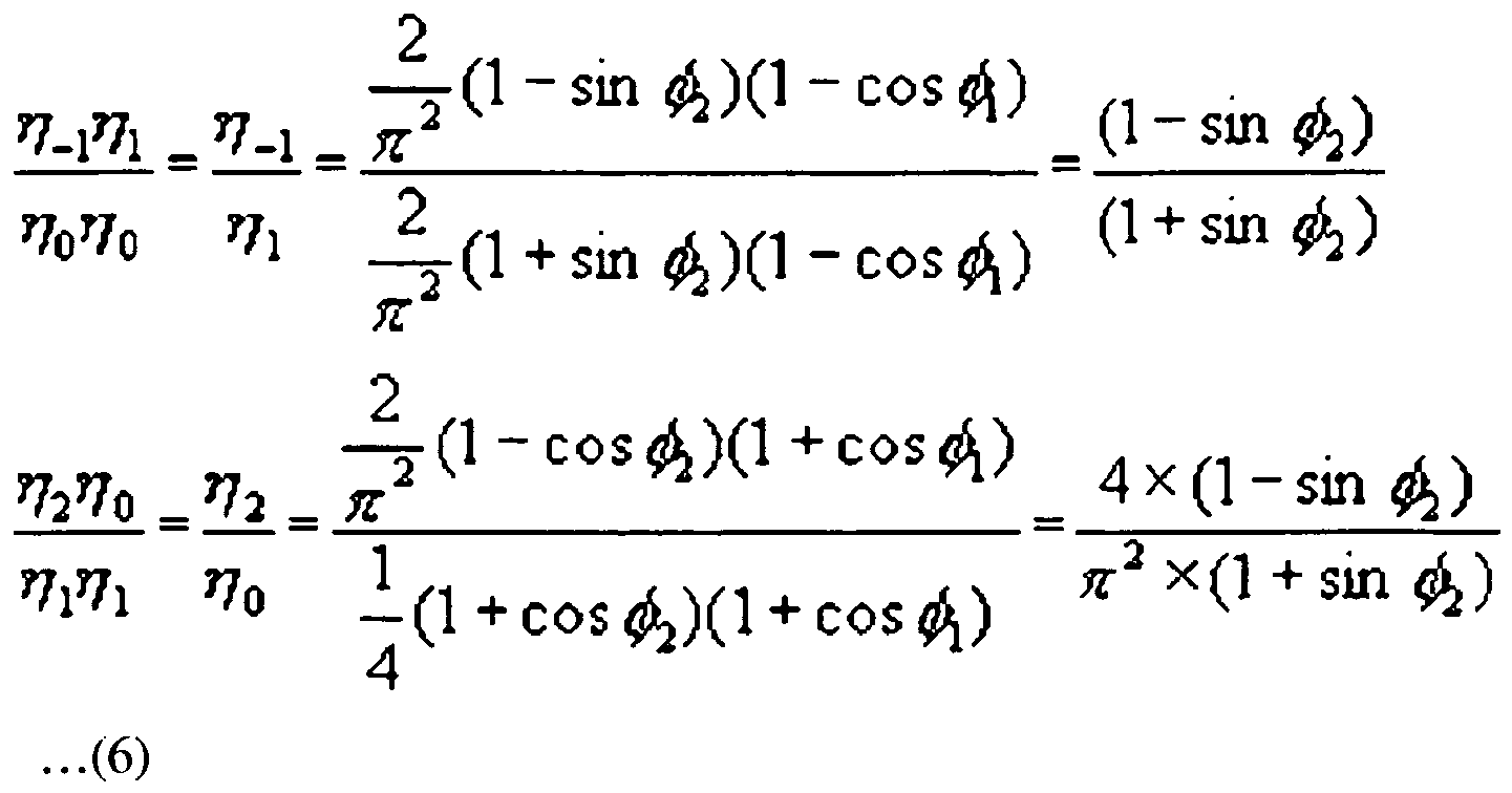
- Here,

and
respectively denote ratios of optical power of a -1st-order/1st-order diffraction beam (noise beam) to optical power of a signal beam and optical power of a 2nd-order/0th-order diffraction beam (noise beam) to optical power of the signal beam. The conditions of the phase variation Φ2 can be deduced from Equation 6. -
FIG. 8 is a graph showing variations in

, and
with respect to the phase variation Φ2. Here,
denotes a ratio of optical power of a +1st-order/-2nd-order or -2nd-order/0th-order diffraction beam to optical power of a signal beam, wherein the +1st-order/-2nd-order or -2 nd-order/0th-order diffraction beam is reflected from a surface of a BD having a rewritable dual layer structure when reproduction is performed with respect to the BD. - As shown in
FIG. 8 ,
and
may be minimized when Φ2= 54.05° and each have a value of about 0.1. Thus, when η0=η1,
and
may each be reduced to be lower than 0.1. -
FIG. 9 is a graph showing variations in the efficiencies of 0th-order, 1st-order, -1st-order, 2nd-order, and -2nd-order diffraction beams according to a phase variation Φ1 when Φ2=54.05°. As shown inFIG. 9 , when the efficiencies of the -1st-order and 2nd-order (-2nd-order) diffraction beams are minimized, the phase variation Φ1 is about 92.26°. When Φ2=54.05° is substituted forEquation 5 so that Φ1=92.26°, efficiency of 'η0= η1' is about 38%, and 'η-1 =η+2 =η-2' is about 4%. Therefore, if the conventional hologram optical device technique as disclosed in Japanese Laid-open Patent No.1992-212730 

, and
to be lower than about 0.1. - As described above, when the widths W01, W12, W23, and W34 of the first, second, third, and fourth steps S1', S2', S3', and S4' are the same and the step differences are different, as in the conventional hologram
optical device 20" disclosed in Japanese Laid-open Patent No.1992-212730 

, and

, and
being minimized is about 10%. - In contrast to the conventional hologram
optical device 20", the hologramoptical device 20 changes the widths of steps of hologram pattern in order to reduce the proportions of

, and
- For example, in the hologram
optical device 20 the heights of steps are the same and the widths of the steps are different from one another so as to minimize

, and
The ratios

, and
in the hologramoptical device 20 can be numerically calculated fromEquations 3 and 4 above. According to an embodiment of the present invention, when the widths W01 and W34 are equal, and the widths W12 and W23 are equal, the widths W01 and W34 are each changed by '-a,' and the widths W12 and W23 are each changed by '+a.' Here, 'a' denotes a duty variation. -
FIG. 10 is a graph showing the efficiencies of -1st-order, -2nd-order, and 2nd-order diffraction beams with respect to duty variations when η0=η1.FIG. 11 is a graph illustrating ratios of

, and
with respect to duty variations when η0=η1. As shown inFIGS. 10 and11 , the efficiencies and the ratios are obtained with respect to the duty variations when a total width T is fixed. - As shown in
FIG. 11 , when the duty variation a is 0.03T, the ratios of optical powers of noise beams to optical powers of signal beams, i.e., the ratios

, and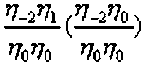
, may be all minimized. When the duty variation a is 0.03T, the ratios
and
are each about 10% and thus almost equal to those of the prior art described with reference toFIG. 8 . The ratio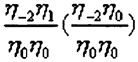
is about 4.2% and thus can be reduced by about 2.4 times that of the prior art. - Table 1 below shows the diffraction efficiencies and ratios


, and
when the hologramoptical device 20, the conventional hologramoptical device 20", and the general hologram optical device 20' are used. -
[Table] Diffraction Efficiency 


0th-order diffra ction beam 1st-order diffra ction beam -1st-order diffrac tion beam 2nd-order diffraction beam -2nd-order diffraction beam Present Invention (d12=d34=d23 ) (W01=W34≠ W12=W23) 38.0 % 38.0 % 4.2% 4.2% 1.6% 11% 4.2% 11% Prior Art (d12=d34≠d23 ) (W01=W12= W23=W34) 38.0 % 38.0 % 4.0% 4.0% 4.0% 10.5% 10.5% 10.5% General Diffraction Device (d12=d34=d23 ) (W01=W12= W23=W34) 38.0 % 38.0 % 5.8% 3% 3% 15% 8% 8% - As shown in Table 1, the
ratio 
indicating a ratio of noise to a signal beam of a HD DVD is 11% in the case of the present invention but 10.5% in the case of the prior art. Theratio 
hardly differs in the cases of the present invention and the prior art. In the case of the present invention the ratios
and
indicating ratios of noise to signal beam of a BD is 11% and 4.2%, respectively, and the sum of the ratios is 15.2%. In the case of the prior art, the ratios
and
are 10.5% and 10.5%, respectively, and the sum of the ratios is 21%. Thus, the widths of steps of a 4-step stairway of each hologram pattern of a hologram optical device according to aspects of the present invention can be adjusted to greatly improve a ratio of noise to a signal beam of the BD compared to the prior art. -
FIG. 12 shows a hologram pattern of the hologramoptical device 20 used to obtain the results of Table 1, according to an embodiment of the present invention. As shown inFIG. 12 , the hologramoptical device 20 may be formed so that a duty variation a is 0.3T, and the heights of the steps each have a phase difference of 0.28π. - When the hologram
optical device 20 as shown inFIG. 12 is used, the use efficiency of an incident 0th-order/returned 0th-order diffraction beam used as a signal beam for the first information storage medium of the first standard, i.e., the BD 1a, is increased. An incident 1st-order/returned 1st-order diffraction beam used as a signal beam for the second information storage medium of the second standard, i.e., theHD DVD 1b, is increased. The use efficiencies of unnecessary diffraction beams, e.g., -1st-order, -2nd-order, and 2nd-order diffraction beams are not increased. As a result, a signal-to-noise ratio (SNR) of an information signal can be improved. - As described above, the hologram
optical device 20 has a 4-step stairway, the step differences of the four steps of the 4-step stairway are equal, the first and fourth steps have the same width of 0.22T, and the second and third steps have the same width of 0.28T so as to reduce noise beams. However, the present invention is not limited thereto. It will be understood by those of ordinary skill in the art that various changes in form and details may be made therein without departing from the spirit and scope of the present invention as defined by the following claims. - The hologram
optical device 20 may constitute a phase type hologram lens. When the hologramoptical device 20 is combined with theobjective lens 30, recording and/or reproduction can be performed with respect to a plurality of optical information storage media, e.g., a BD and a HD DVD, using one light source. -
FIG. 13 schematically illustrates an optical information storage medium system employing the compatibleoptical pickup 10, according to an embodiment of the present invention. As shown inFIG. 13 , the optical information storage medium system includes aspindle motor 312, the compatibleoptical pickup 10, adriver 307, and acontroller 309. Thespindle motor 312 rotates an opticalinformation storage medium 1. The compatibleoptical pickup 10 is moveably installed in a radius direction of the opticalinformation storage medium 1 so as to record and/or reproduce information on and/or from the opticalinformation storage medium 1. Thedriver 307 drives thespindle motor 312 and the compatibleoptical pickup 10. Thecontroller 309 controls focus, tracking, and/or tilt servos of the compatibleoptical pickup 10.Reference numerals information storage medium 1. The optical information storage medium system may be incorporated into a stand-alone recording and/or reproducing apparatus or may be incorporated into another device, such as a computer or video game console. - A beam reflected from the optical
information storage medium 1 is detected by thePD 19 of the compatibleoptical pickup 10, photoelectrically transformed into an electrical signal, and input to thecontroller 309 through thedriver 307. Thedriver 307 controls a rotation speed of thespindle motor 312, amplifies an input signal, and drives the compatibleoptical pickup 10. Thecontroller 309 transmits focus, tracking, and/or tilt servo commands, which are controlled based on the signal input from thedriver 307, to thedriver 307 so as to realize focusing, tracking, and/or tilt operations. The optical information storage medium system employing the compatibleoptical pickup 10 of the present invention may use both a BD and an HD DVD. - Although a few embodiments of the present invention have been shown and described, it would be appreciated by those skilled in the art that changes may be made in this embodiment without departing from the invention, the scope of which is defined in the claims.
Claims (12)
- A hologram optical device (20) comprising:a hologram (22) including a pattern comprising a plurality of shapes, each respective shape having a period in a 4-step stairway shape, wherein at least one of first, second, third, and fourth steps of each of the 4-step stairway shapes has a different width from at least one other step;the hologram (22) is formed so that the widths of the first and fourth steps of each respective shape are equal to each other and equal to or greater than 0.16T and less than 0.25T, and the widths of the second and third steps of each respective shape are equal to each other and each equal to 0.5T-the width of the first step, where T is a width of the period of the pattern; anda first area (21) consisting of a plurality of step-shaped concentric rings, in which the hologram (22) is formed; anda second area (23) consisting of a plurality of step-shaped concentric rings surrounding the first area (21), in which a step-shaped hologram (24) is formed in a step shape symmetrical to a step shape of the hologram (22) formed in the first area (21).
- The hologram optical device of claim 1, wherein:the hologram (22) is formed so that a phase variation determined by a step difference between the first and second steps is equal to a phase variation determined by a step difference between the second and third steps and is equal to a phase variation determined by a step difference between the third and fourth steps.
- A compatible optical pickup (10) that uses both a first optical information storage medium (1 a) of a first standard and a second optical information storage medium (1b) of a second standard, the second optical information storage medium (1b) having a different thickness from the first optical information storage medium (1a), the compatible optical pickup (10) comprising:a light source (11) to emit a beam having a predetermined wavelength;an objective lens (30) to focus an incident beam onto an optical information storage medium (1a/1b); andthe hologram optical device (20) of any one of claims 1 to 2 located in the path of the light source beam to diffract the beam incident from the light source as 0th-order and 1st-order diffraction beams.
- The compatible optical pickup (10) of claim 3, wherein the first area (21) of the hologram optical device (20) is adapted to diverge a 1 st-order diffraction beam.
- The compatible optical pickup of claim 4, wherein the second area (23) of the hologram optical device (20) is adapted to diffract the incident beam as a 0th-order diffraction beam and a convergent 1 st-order diffraction beam.
- The compatible optical pickup of claim 5, wherein the second area (23) is formed so that a diffraction efficiency of the 0th-order diffraction beam is similar to or greater than a diffraction efficiency of the 1 st-order diffraction beam.
- The compatible optical pickup of any one of claims 3 to 6, wherein the first area (21) is formed so that a diffraction efficiency of a 0th-order diffraction beam is approximate to the diffraction efficiency of the 1 st-order diffraction beam.
- The compatible optical pickup of any one of claims 3 to 7, wherein a thickness of the first optical information storage medium (1a) is 0.1 mm, and a thickness of the second optical information storage medium (1b) is 0.6 mm.
- The compatible optical pickup (10) of any one of claims 3 to 8, wherein the first optical information storage medium (1a) is in accordance with a BD (Blu-ray disc) standard, and the second optical information storage medium (1b) is in accordance with an HD DVD (high definition digital versatile disc) standard.
- The compatible optical pickup (10) of claim 10, wherein the light source emits a blue beam having a wavelength between 400 nm and 420 nm.
- The compatible optical pickup (11) of any one of claims 4 to 10, wherein the objective lens (30) has a first NA (numerical aperture) suitable for the first optical information storage medium (1a) of the first standard, and the first area (21) of the hologram optical device (20) is formed so that an outmost diameter of the first area (21) forms a second NA suitable for the second optical information storage medium (1b) of the second standard when the hologram optical device (20) is combined with the objective lens (30),
wherein the first NA is 0.85 and the second NA is 0.65. - An optical information storage system comprising:the compatible optical pickup (10) of any one of claims 3 to 11 to record and/or reproduce data to/from both a first optical information storage medium (1a) of a first standard and a second optical information storage medium (1b) of a second standard, the second optical information storage medium (1b) having a different thickness from the first optical information storage medium (1a); anda controller (309) to control the compatible optical pickup (10).
Applications Claiming Priority (2)
| Application Number | Priority Date | Filing Date | Title |
|---|---|---|---|
| KR1020070048729A KR20080101516A (en) | 2007-05-18 | 2007-05-18 | Hologram element, compatible optical pickup having same, and optical information storage medium system employing same |
| PCT/KR2008/000381 WO2008143395A1 (en) | 2007-05-18 | 2008-01-22 | Hologram optical device, and compatible optical pickup having the hologram optical device and optical information storage medium system employing the compatible optical pickup |
Publications (3)
| Publication Number | Publication Date |
|---|---|
| EP2149139A1 EP2149139A1 (en) | 2010-02-03 |
| EP2149139A4 EP2149139A4 (en) | 2010-08-11 |
| EP2149139B1 true EP2149139B1 (en) | 2012-06-20 |
Family
ID=40027343
Family Applications (1)
| Application Number | Title | Priority Date | Filing Date |
|---|---|---|---|
| EP08704903A Not-in-force EP2149139B1 (en) | 2007-05-18 | 2008-01-22 | Hologram optical device, and compatible optical pickup having the hologram optical device and optical information storage system employing the compatible optical pickup |
Country Status (7)
| Country | Link |
|---|---|
| US (1) | US8089849B2 (en) |
| EP (1) | EP2149139B1 (en) |
| JP (1) | JP2010528399A (en) |
| KR (1) | KR20080101516A (en) |
| CN (1) | CN101681644A (en) |
| TW (1) | TWI362036B (en) |
| WO (1) | WO2008143395A1 (en) |
Families Citing this family (4)
| Publication number | Priority date | Publication date | Assignee | Title |
|---|---|---|---|---|
| US8085645B2 (en) * | 2009-03-13 | 2011-12-27 | Panasonic Corporation | Optical pickup device and optical disk apparatus |
| JP5310386B2 (en) * | 2009-06-18 | 2013-10-09 | ソニー株式会社 | Objective lens, optical pickup and optical disk apparatus |
| WO2013140534A1 (en) * | 2012-03-21 | 2013-09-26 | 株式会社 東芝 | Recording/reproduction device |
| CN103955065A (en) * | 2014-03-31 | 2014-07-30 | 何东阳 | High-brightness naked eye three-dimensional display device |
Family Cites Families (14)
| Publication number | Priority date | Publication date | Assignee | Title |
|---|---|---|---|---|
| JP2796196B2 (en) | 1990-04-12 | 1998-09-10 | 松下電器産業株式会社 | Optical head device |
| JP3396890B2 (en) | 1992-02-21 | 2003-04-14 | 松下電器産業株式会社 | Hologram, optical head device and optical system using the same |
| JP2532818B2 (en) * | 1993-02-01 | 1996-09-11 | 松下電器産業株式会社 | Objective lens and optical head device |
| KR100269105B1 (en) | 1995-12-07 | 2000-10-16 | 윤종용 | Optical pickup for recording and playback compatible with discs of different thickness |
| JP3575017B2 (en) * | 1996-05-16 | 2004-10-06 | ソニー株式会社 | Recording / reproducing apparatus and method |
| JPH1010308A (en) * | 1996-06-21 | 1998-01-16 | Matsushita Electric Ind Co Ltd | Hologram, condensing optical system using hologram, optical head device and optical disc device having the condensing optical system |
| JP3662751B2 (en) * | 1998-11-18 | 2005-06-22 | 日本電気株式会社 | Optical head device |
| KR100332853B1 (en) | 1999-06-14 | 2002-04-17 | 성재갑 | Flame Retardant Thermoplastic Resin Composition with Excellent Environmental Stress Crack Resistance and Impact Resistance |
| KR100546351B1 (en) * | 2003-07-25 | 2006-01-26 | 삼성전자주식회사 | Compatible optical pickups and optical recording and / or reproducing apparatus employing the same |
| TW200532679A (en) * | 2004-02-13 | 2005-10-01 | Konica Minolta Opto Inc | Optical pickup apparatus and diffractive optical element for optical pickup apparatus |
| JP4407421B2 (en) * | 2004-03-26 | 2010-02-03 | コニカミノルタオプト株式会社 | Optical element and optical pickup device |
| JP2005293765A (en) * | 2004-04-02 | 2005-10-20 | Konica Minolta Opto Inc | Optical pickup |
| KR100782813B1 (en) * | 2005-07-15 | 2007-12-06 | 삼성전자주식회사 | Active correction device and compatible optical pickup and optical recording and / or reproducing apparatus employing the same |
| WO2007020787A1 (en) * | 2005-08-18 | 2007-02-22 | Nec Corporation | Optical head device and optical information recording/reproducing device |
-
2007
- 2007-05-18 KR KR1020070048729A patent/KR20080101516A/en not_active Ceased
-
2008
- 2008-01-22 EP EP08704903A patent/EP2149139B1/en not_active Not-in-force
- 2008-01-22 CN CN200880015949A patent/CN101681644A/en active Pending
- 2008-01-22 JP JP2010508282A patent/JP2010528399A/en active Pending
- 2008-01-22 WO PCT/KR2008/000381 patent/WO2008143395A1/en not_active Ceased
- 2008-01-23 US US12/018,308 patent/US8089849B2/en not_active Expired - Fee Related
- 2008-03-05 TW TW097107726A patent/TWI362036B/en not_active IP Right Cessation
Also Published As
| Publication number | Publication date |
|---|---|
| KR20080101516A (en) | 2008-11-21 |
| US20080285419A1 (en) | 2008-11-20 |
| WO2008143395A1 (en) | 2008-11-27 |
| EP2149139A1 (en) | 2010-02-03 |
| CN101681644A (en) | 2010-03-24 |
| TWI362036B (en) | 2012-04-11 |
| US8089849B2 (en) | 2012-01-03 |
| JP2010528399A (en) | 2010-08-19 |
| TW200847153A (en) | 2008-12-01 |
| EP2149139A4 (en) | 2010-08-11 |
Similar Documents
| Publication | Publication Date | Title |
|---|---|---|
| KR100965884B1 (en) | Optical pickup | |
| US20080084798A1 (en) | Optical pick-up head, optical information apparatus, and optical information reproducing method | |
| US8089849B2 (en) | Hologram optical device, and compatible optical pickup having the hologram optical device and optical information storage medium system employing the compatible optical pickup | |
| US7924682B2 (en) | Unit to remove crosstalk in multi-layered disk, optical pickup including the unit, and optical recording and/or reproducing apparatus including the optical pickup | |
| KR20050006887A (en) | Optical pickup capable of reducing focus offset and optical recording and/or reproducing apparatus employing it | |
| KR101312633B1 (en) | Hologram optical device and compatible optical pickup and optical information storage medium system employing the same | |
| US8493831B2 (en) | Compatible optical pickup and optical recording and/or reproducing apparatus employing the same | |
| US20070041287A1 (en) | Optical pickup apparatus capable of detecting and compensating for spherical aberration caused by thickness variation of recording layer | |
| US7298675B2 (en) | Multilayer recording medium and optical pickup for recording and/or reproducing the same | |
| EP1968055B1 (en) | Optical pick-up and disc apparatus having the same | |
| KR101187710B1 (en) | Optical pick-up device | |
| EP1612781A2 (en) | Optical disc apparatus | |
| WO2007013772A1 (en) | Optical pickup and optical recording and/or re¬ producing apparatus employing the same | |
| EP1939869B1 (en) | Optical pickup apparatus | |
| KR100846806B1 (en) | Unit for removing layer crosstalk of multi-layer disc, optical pick-up apparatus employing the same and optical recording/reproducing apparatus | |
| WO2009057868A1 (en) | Optical pickup and optical information storage medium system employing the optical pickup | |
| JP2011150767A (en) | Optical head | |
| HK1120156B (en) | Unit to remove crosstalk in multi-layered disk, optical pickup including the unit, and optical recording and/or reproducing apparatus including the optical pickup | |
| KR20080028550A (en) | Optical pickup |
Legal Events
| Date | Code | Title | Description |
|---|---|---|---|
| PUAI | Public reference made under article 153(3) epc to a published international application that has entered the european phase |
Free format text: ORIGINAL CODE: 0009012 |
|
| 17P | Request for examination filed |
Effective date: 20091112 |
|
| AK | Designated contracting states |
Kind code of ref document: A1 Designated state(s): AT BE BG CH CY CZ DE DK EE ES FI FR GB GR HR HU IE IS IT LI LT LU LV MC MT NL NO PL PT RO SE SI SK TR |
|
| AX | Request for extension of the european patent |
Extension state: AL BA MK RS |
|
| A4 | Supplementary search report drawn up and despatched |
Effective date: 20100713 |
|
| DAX | Request for extension of the european patent (deleted) | ||
| 17Q | First examination report despatched |
Effective date: 20110801 |
|
| GRAP | Despatch of communication of intention to grant a patent |
Free format text: ORIGINAL CODE: EPIDOSNIGR1 |
|
| RTI1 | Title (correction) |
Free format text: HOLOGRAM OPTICAL DEVICE, AND COMPATIBLE OPTICAL PICKUP HAVING THE HOLOGRAM OPTICAL DEVICE AND OPTICAL INFORMATION STORAGE SYSTEM EMPLOYING THE COMPATIBLE OPTICAL PICKUP |
|
| GRAS | Grant fee paid |
Free format text: ORIGINAL CODE: EPIDOSNIGR3 |
|
| GRAA | (expected) grant |
Free format text: ORIGINAL CODE: 0009210 |
|
| AK | Designated contracting states |
Kind code of ref document: B1 Designated state(s): AT BE BG CH CY CZ DE DK EE ES FI FR GB GR HR HU IE IS IT LI LT LU LV MC MT NL NO PL PT RO SE SI SK TR |
|
| REG | Reference to a national code |
Ref country code: GB Ref legal event code: FG4D |
|
| REG | Reference to a national code |
Ref country code: CH Ref legal event code: EP |
|
| REG | Reference to a national code |
Ref country code: AT Ref legal event code: REF Ref document number: 563435 Country of ref document: AT Kind code of ref document: T Effective date: 20120715 |
|
| REG | Reference to a national code |
Ref country code: IE Ref legal event code: FG4D |
|
| REG | Reference to a national code |
Ref country code: DE Ref legal event code: R096 Ref document number: 602008016445 Country of ref document: DE Effective date: 20120816 |
|
| RAP2 | Party data changed (patent owner data changed or rights of a patent transferred) |
Owner name: SAMSUNG ELECTRONICS CO., LTD. |
|
| REG | Reference to a national code |
Ref country code: NL Ref legal event code: T3 |
|
| PG25 | Lapsed in a contracting state [announced via postgrant information from national office to epo] |
Ref country code: FI Free format text: LAPSE BECAUSE OF FAILURE TO SUBMIT A TRANSLATION OF THE DESCRIPTION OR TO PAY THE FEE WITHIN THE PRESCRIBED TIME-LIMIT Effective date: 20120620 Ref country code: NO Free format text: LAPSE BECAUSE OF FAILURE TO SUBMIT A TRANSLATION OF THE DESCRIPTION OR TO PAY THE FEE WITHIN THE PRESCRIBED TIME-LIMIT Effective date: 20120920 Ref country code: LT Free format text: LAPSE BECAUSE OF FAILURE TO SUBMIT A TRANSLATION OF THE DESCRIPTION OR TO PAY THE FEE WITHIN THE PRESCRIBED TIME-LIMIT Effective date: 20120620 Ref country code: SE Free format text: LAPSE BECAUSE OF FAILURE TO SUBMIT A TRANSLATION OF THE DESCRIPTION OR TO PAY THE FEE WITHIN THE PRESCRIBED TIME-LIMIT Effective date: 20120620 |
|
| REG | Reference to a national code |
Ref country code: AT Ref legal event code: MK05 Ref document number: 563435 Country of ref document: AT Kind code of ref document: T Effective date: 20120620 |
|
| REG | Reference to a national code |
Ref country code: LT Ref legal event code: MG4D Effective date: 20120620 |
|
| PG25 | Lapsed in a contracting state [announced via postgrant information from national office to epo] |
Ref country code: HR Free format text: LAPSE BECAUSE OF FAILURE TO SUBMIT A TRANSLATION OF THE DESCRIPTION OR TO PAY THE FEE WITHIN THE PRESCRIBED TIME-LIMIT Effective date: 20120620 Ref country code: GR Free format text: LAPSE BECAUSE OF FAILURE TO SUBMIT A TRANSLATION OF THE DESCRIPTION OR TO PAY THE FEE WITHIN THE PRESCRIBED TIME-LIMIT Effective date: 20120921 Ref country code: SI Free format text: LAPSE BECAUSE OF FAILURE TO SUBMIT A TRANSLATION OF THE DESCRIPTION OR TO PAY THE FEE WITHIN THE PRESCRIBED TIME-LIMIT Effective date: 20120620 Ref country code: LV Free format text: LAPSE BECAUSE OF FAILURE TO SUBMIT A TRANSLATION OF THE DESCRIPTION OR TO PAY THE FEE WITHIN THE PRESCRIBED TIME-LIMIT Effective date: 20120620 |
|
| PG25 | Lapsed in a contracting state [announced via postgrant information from national office to epo] |
Ref country code: CZ Free format text: LAPSE BECAUSE OF FAILURE TO SUBMIT A TRANSLATION OF THE DESCRIPTION OR TO PAY THE FEE WITHIN THE PRESCRIBED TIME-LIMIT Effective date: 20120620 Ref country code: SK Free format text: LAPSE BECAUSE OF FAILURE TO SUBMIT A TRANSLATION OF THE DESCRIPTION OR TO PAY THE FEE WITHIN THE PRESCRIBED TIME-LIMIT Effective date: 20120620 Ref country code: IS Free format text: LAPSE BECAUSE OF FAILURE TO SUBMIT A TRANSLATION OF THE DESCRIPTION OR TO PAY THE FEE WITHIN THE PRESCRIBED TIME-LIMIT Effective date: 20121020 Ref country code: AT Free format text: LAPSE BECAUSE OF FAILURE TO SUBMIT A TRANSLATION OF THE DESCRIPTION OR TO PAY THE FEE WITHIN THE PRESCRIBED TIME-LIMIT Effective date: 20120620 Ref country code: BE Free format text: LAPSE BECAUSE OF FAILURE TO SUBMIT A TRANSLATION OF THE DESCRIPTION OR TO PAY THE FEE WITHIN THE PRESCRIBED TIME-LIMIT Effective date: 20120620 Ref country code: CY Free format text: LAPSE BECAUSE OF FAILURE TO SUBMIT A TRANSLATION OF THE DESCRIPTION OR TO PAY THE FEE WITHIN THE PRESCRIBED TIME-LIMIT Effective date: 20120620 Ref country code: RO Free format text: LAPSE BECAUSE OF FAILURE TO SUBMIT A TRANSLATION OF THE DESCRIPTION OR TO PAY THE FEE WITHIN THE PRESCRIBED TIME-LIMIT Effective date: 20120620 Ref country code: EE Free format text: LAPSE BECAUSE OF FAILURE TO SUBMIT A TRANSLATION OF THE DESCRIPTION OR TO PAY THE FEE WITHIN THE PRESCRIBED TIME-LIMIT Effective date: 20120620 |
|
| PG25 | Lapsed in a contracting state [announced via postgrant information from national office to epo] |
Ref country code: IT Free format text: LAPSE BECAUSE OF FAILURE TO SUBMIT A TRANSLATION OF THE DESCRIPTION OR TO PAY THE FEE WITHIN THE PRESCRIBED TIME-LIMIT Effective date: 20120620 Ref country code: PL Free format text: LAPSE BECAUSE OF FAILURE TO SUBMIT A TRANSLATION OF THE DESCRIPTION OR TO PAY THE FEE WITHIN THE PRESCRIBED TIME-LIMIT Effective date: 20120620 Ref country code: PT Free format text: LAPSE BECAUSE OF FAILURE TO SUBMIT A TRANSLATION OF THE DESCRIPTION OR TO PAY THE FEE WITHIN THE PRESCRIBED TIME-LIMIT Effective date: 20121022 |
|
| PLBE | No opposition filed within time limit |
Free format text: ORIGINAL CODE: 0009261 |
|
| STAA | Information on the status of an ep patent application or granted ep patent |
Free format text: STATUS: NO OPPOSITION FILED WITHIN TIME LIMIT |
|
| PG25 | Lapsed in a contracting state [announced via postgrant information from national office to epo] |
Ref country code: ES Free format text: LAPSE BECAUSE OF FAILURE TO SUBMIT A TRANSLATION OF THE DESCRIPTION OR TO PAY THE FEE WITHIN THE PRESCRIBED TIME-LIMIT Effective date: 20121001 Ref country code: DK Free format text: LAPSE BECAUSE OF FAILURE TO SUBMIT A TRANSLATION OF THE DESCRIPTION OR TO PAY THE FEE WITHIN THE PRESCRIBED TIME-LIMIT Effective date: 20120620 |
|
| 26N | No opposition filed |
Effective date: 20130321 |
|
| REG | Reference to a national code |
Ref country code: DE Ref legal event code: R097 Ref document number: 602008016445 Country of ref document: DE Effective date: 20130321 |
|
| PG25 | Lapsed in a contracting state [announced via postgrant information from national office to epo] |
Ref country code: BG Free format text: LAPSE BECAUSE OF FAILURE TO SUBMIT A TRANSLATION OF THE DESCRIPTION OR TO PAY THE FEE WITHIN THE PRESCRIBED TIME-LIMIT Effective date: 20120920 |
|
| PG25 | Lapsed in a contracting state [announced via postgrant information from national office to epo] |
Ref country code: MC Free format text: LAPSE BECAUSE OF NON-PAYMENT OF DUE FEES Effective date: 20130131 |
|
| REG | Reference to a national code |
Ref country code: CH Ref legal event code: PL |
|
| REG | Reference to a national code |
Ref country code: IE Ref legal event code: MM4A |
|
| PG25 | Lapsed in a contracting state [announced via postgrant information from national office to epo] |
Ref country code: LI Free format text: LAPSE BECAUSE OF NON-PAYMENT OF DUE FEES Effective date: 20130131 Ref country code: CH Free format text: LAPSE BECAUSE OF NON-PAYMENT OF DUE FEES Effective date: 20130131 |
|
| PG25 | Lapsed in a contracting state [announced via postgrant information from national office to epo] |
Ref country code: IE Free format text: LAPSE BECAUSE OF NON-PAYMENT OF DUE FEES Effective date: 20130122 |
|
| PG25 | Lapsed in a contracting state [announced via postgrant information from national office to epo] |
Ref country code: MT Free format text: LAPSE BECAUSE OF FAILURE TO SUBMIT A TRANSLATION OF THE DESCRIPTION OR TO PAY THE FEE WITHIN THE PRESCRIBED TIME-LIMIT Effective date: 20120620 |
|
| PG25 | Lapsed in a contracting state [announced via postgrant information from national office to epo] |
Ref country code: TR Free format text: LAPSE BECAUSE OF FAILURE TO SUBMIT A TRANSLATION OF THE DESCRIPTION OR TO PAY THE FEE WITHIN THE PRESCRIBED TIME-LIMIT Effective date: 20120620 |
|
| PG25 | Lapsed in a contracting state [announced via postgrant information from national office to epo] |
Ref country code: LU Free format text: LAPSE BECAUSE OF NON-PAYMENT OF DUE FEES Effective date: 20130122 Ref country code: HU Free format text: LAPSE BECAUSE OF FAILURE TO SUBMIT A TRANSLATION OF THE DESCRIPTION OR TO PAY THE FEE WITHIN THE PRESCRIBED TIME-LIMIT; INVALID AB INITIO Effective date: 20080122 |
|
| REG | Reference to a national code |
Ref country code: FR Ref legal event code: PLFP Year of fee payment: 9 |
|
| REG | Reference to a national code |
Ref country code: FR Ref legal event code: PLFP Year of fee payment: 10 |
|
| REG | Reference to a national code |
Ref country code: FR Ref legal event code: PLFP Year of fee payment: 11 |
|
| PGFP | Annual fee paid to national office [announced via postgrant information from national office to epo] |
Ref country code: FR Payment date: 20171226 Year of fee payment: 11 Ref country code: NL Payment date: 20171222 Year of fee payment: 11 |
|
| PGFP | Annual fee paid to national office [announced via postgrant information from national office to epo] |
Ref country code: GB Payment date: 20171222 Year of fee payment: 11 |
|
| PGFP | Annual fee paid to national office [announced via postgrant information from national office to epo] |
Ref country code: DE Payment date: 20171221 Year of fee payment: 11 |
|
| REG | Reference to a national code |
Ref country code: DE Ref legal event code: R119 Ref document number: 602008016445 Country of ref document: DE |
|
| REG | Reference to a national code |
Ref country code: NL Ref legal event code: MM Effective date: 20190201 |
|
| GBPC | Gb: european patent ceased through non-payment of renewal fee |
Effective date: 20190122 |
|
| PG25 | Lapsed in a contracting state [announced via postgrant information from national office to epo] |
Ref country code: DE Free format text: LAPSE BECAUSE OF NON-PAYMENT OF DUE FEES Effective date: 20190801 Ref country code: NL Free format text: LAPSE BECAUSE OF NON-PAYMENT OF DUE FEES Effective date: 20190201 Ref country code: FR Free format text: LAPSE BECAUSE OF NON-PAYMENT OF DUE FEES Effective date: 20190131 |
|
| PG25 | Lapsed in a contracting state [announced via postgrant information from national office to epo] |
Ref country code: GB Free format text: LAPSE BECAUSE OF NON-PAYMENT OF DUE FEES Effective date: 20190122 |