EP2148502B1 - Bildverarbeitungsvorrichtung und zugehöriges Verfahren - Google Patents
Bildverarbeitungsvorrichtung und zugehöriges Verfahren Download PDFInfo
- Publication number
- EP2148502B1 EP2148502B1 EP09165598A EP09165598A EP2148502B1 EP 2148502 B1 EP2148502 B1 EP 2148502B1 EP 09165598 A EP09165598 A EP 09165598A EP 09165598 A EP09165598 A EP 09165598A EP 2148502 B1 EP2148502 B1 EP 2148502B1
- Authority
- EP
- European Patent Office
- Prior art keywords
- image
- region
- raw
- image data
- development process
- Prior art date
- Legal status (The legal status is an assumption and is not a legal conclusion. Google has not performed a legal analysis and makes no representation as to the accuracy of the status listed.)
- Not-in-force
Links
- 238000000034 method Methods 0.000 title claims abstract description 169
- 238000012545 processing Methods 0.000 title claims description 22
- 230000008569 process Effects 0.000 claims abstract description 155
- 238000011161 development Methods 0.000 claims abstract description 94
- 238000012360 testing method Methods 0.000 claims description 11
- 239000000284 extract Substances 0.000 claims description 6
- 230000002093 peripheral effect Effects 0.000 claims description 4
- 238000003672 processing method Methods 0.000 claims description 3
- 238000004590 computer program Methods 0.000 claims 1
- 238000005314 correlation function Methods 0.000 claims 1
- 230000001419 dependent effect Effects 0.000 claims 1
- 238000004364 calculation method Methods 0.000 description 11
- 230000006870 function Effects 0.000 description 10
- 230000006866 deterioration Effects 0.000 description 7
- FFBHFFJDDLITSX-UHFFFAOYSA-N benzyl N-[2-hydroxy-4-(3-oxomorpholin-4-yl)phenyl]carbamate Chemical compound OC1=C(NC(=O)OCC2=CC=CC=C2)C=CC(=C1)N1CCOCC1=O FFBHFFJDDLITSX-UHFFFAOYSA-N 0.000 description 5
- 238000001514 detection method Methods 0.000 description 5
- 230000005540 biological transmission Effects 0.000 description 2
- 238000006243 chemical reaction Methods 0.000 description 2
- 238000010586 diagram Methods 0.000 description 2
- 230000000694 effects Effects 0.000 description 2
- 230000011514 reflex Effects 0.000 description 2
- 230000008901 benefit Effects 0.000 description 1
- 239000003086 colorant Substances 0.000 description 1
- 230000000295 complement effect Effects 0.000 description 1
- 238000012937 correction Methods 0.000 description 1
- 238000013144 data compression Methods 0.000 description 1
- 238000000605 extraction Methods 0.000 description 1
- 238000003780 insertion Methods 0.000 description 1
- 230000037431 insertion Effects 0.000 description 1
- 229910044991 metal oxide Inorganic materials 0.000 description 1
- 150000004706 metal oxides Chemical class 0.000 description 1
- 238000012986 modification Methods 0.000 description 1
- 230000004048 modification Effects 0.000 description 1
- 230000003287 optical effect Effects 0.000 description 1
- 230000001737 promoting effect Effects 0.000 description 1
- 230000009467 reduction Effects 0.000 description 1
- 230000004044 response Effects 0.000 description 1
- 239000004065 semiconductor Substances 0.000 description 1
- 230000035945 sensitivity Effects 0.000 description 1
- 238000000926 separation method Methods 0.000 description 1
Images




Classifications
-
- H—ELECTRICITY
- H04—ELECTRIC COMMUNICATION TECHNIQUE
- H04N—PICTORIAL COMMUNICATION, e.g. TELEVISION
- H04N23/00—Cameras or camera modules comprising electronic image sensors; Control thereof
- H04N23/60—Control of cameras or camera modules
- H04N23/63—Control of cameras or camera modules by using electronic viewfinders
-
- H—ELECTRICITY
- H04—ELECTRIC COMMUNICATION TECHNIQUE
- H04N—PICTORIAL COMMUNICATION, e.g. TELEVISION
- H04N23/00—Cameras or camera modules comprising electronic image sensors; Control thereof
- H04N23/80—Camera processing pipelines; Components thereof
Definitions
- the present invention relates to an image processing apparatus that applies an image process to a photographic image, and a method thereof.
- a digital camera converts light focused on a sensing device such as a CCD (charge coupled device) or CMOS (complementary metal oxide semiconductor) sensor into an electrical signal, and saves a photographic image that has undergone an image process inside the camera on a recording medium as digital data.
- a data format a data compression format such as JPEG (Joint Photographic Experts Group) is generally used. In recent years, digital data can be saved in a photographic data format that allows retouching with a higher degree of freedom.
- Photographic image data is obtained by converting a signal output from a sensing device into digital data (to be referred to as RAW data hereinafter), without applying demosaicing. Therefore, this RAW data cannot be displayed as a normal image as it is.
- Fig. 8 is a view showing a Bayer arrangement known as a typical color filter arrangement used in a 1-CCD type digital camera or digital video camera.
- a signal of another color is calculated by interpolating signals of neighboring elements. This interpolation process will be referred to as demosaicing hereinafter.
- FIG. 9A shows an R plane
- Fig. 9B shows a G plane
- Fig. 9C shows a B plane. Note that "zero" is inserted in a pixel whose value is unknown (a pixel corresponding to an element in front of which a filter of a color other than the color of interest is arranged) in each plane.
- Figs. 10A and 10B show convolution filters, which are used to interpolate the respective planes to perform demosaicing.
- Fig. 10A shows a filter used to interpolate the R and B planes
- Fig. 10B shows a filter used to interpolate the G plane.
- Figs. 11A and 11B show how the G plane is demosaiced.
- Fig. 11A shows the state of the G plane before demosaicing, in which the value of a central pixel is unknown, and zero is inserted.
- Fig. 11B shows the state of the G plane after demosaicing, in which the average value of values of upper, lower, right, and left neighboring pixels is assigned to the central pixel whose value is unknown.
- a pixel whose value is unknown is interpolated using the values of surrounding pixels as in the G plane.
- demosaicing process can also be attained by various other methods in addition to the aforementioned method.
- a method of adaptively interpolating an unknown value with the average of the values of upper and lower neighboring pixels or with the average of the values of right and left neighboring pixels instead of the average of the values of upper, lower, right, and left neighboring pixels may be used.
- RAW data is temporarily saved in a recording medium at the time of image capture, and then undergoes an image process such as a demosaicing process by software or the like which runs on a personal computer (PC).
- An image after the image process, can be displayed or saved in a recording medium after it is converted into a general-purpose data format such as JPEG. That is, the process for using RAW data in a digital camera can be reduced to an exposure process and development process in a film camera.
- RAW data user adjustments of an image process corresponding to development (to be referred to as a development process) are allowed, thus increasing the degree of freedom in retouching. Since the RAW data has a large number of bits per pixel, and is losslessly compressed, a development process with less deterioration of image quality can be attained.
- Software used to implement the development process (to be referred to as development software hereinafter) generally includes an interface of a display function of displaying an image after the development process, and an interface of an adjustment function of adjusting parameters for the development process.
- the parameters for the development process that allow user adjustments include parameters of an edge-emphasis process, those of a blur process, color adjustment parameters, and those associated with demosaicing.
- the user adjusts the parameters for the development process while observing a displayed image, and updates the display image based on the adjusted parameters for the development process.
- the user decides the parameters for the development process to obtain a desired display image by repeating this sequence.
- US 2005/0174449 discloses a developing process or editing process, with a high response, for raw images obtained by image sensing by a digital camera or the like.
- an extraction area in the raw image data is determined on the basis of the size of an image display area in which a processed image is displayed and a magnification set at this time.
- a developing process is then performed for partial raw image data in the determined area, and the resultant data is displayed in the image display area.
- the present invention in its first aspect provides an image processing apparatus as specified in claims 1 to 10.
- the present invention in its second aspect provides an image processing method as specified in claims 11 and 12.
- the present invention in its third aspect provides a program as specified in claims 13 and 14.
- a program can be provided by itself or carried by a carrier medium as specified in claim 15.
- the carrier medium may be a recording or other storage medium.
- the carrier medium may also be a transmission medium.
- the transmission medium may be a signal.
- the present invention is able to improve processing efficiency in a development process and to allow to obtain a processing result that the user intended.
- Fig. 1 is a block diagram showing the arrangement of an image processing apparatus.
- Fig. 2 is a view showing an overview of processes by a development process application according to the first embodiment.
- Fig. 3 is a flowchart for explaining a development process according to the first embodiment.
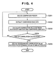
- Fig. 4 is a flowchart for explaining correlation calculations.
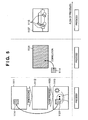
- Fig. 5 is a view showing an overview of processes by a development process application according to the second embodiment.
- Fig. 6 is a flowchart for explaining a development process according to the second embodiment.
- Fig. 7 is a view showing an example of a test chart.
- Fig. 8 is a view showing a Bayer arrangement.
- Figs. 9A to 9C are views for explaining plane separation and zero insertion.
- Figs. 10A and 10B are views showing an example of filters used in demosaicing.
- Figs. 11A and 11B are views for explaining demosaicing.
- Figs. 12A and 12B are views for explaining "maze artifact".
- Fig. 1 is a block diagram showing the arrangement of an image processing apparatus.
- a microprocessor (CPU) 101 executes an operating system (OS) and various programs stored in a read only memory (ROM) of a main memory 102 and hard disk drive (HDD) 105 using a random access memory (RAM) of the main memory 102 as a work memory. Then, the CPU 101 controls respective components via a system bus 114 such as a peripheral component interconnect (PCI) bus. Furthermore, the CPU 101 executes various programs including a development process application (to be described later).
- OS operating system
- ROM read only memory
- HDD hard disk drive
- RAM random access memory
- PCI peripheral component interconnect
- the CPU 101 accesses the HDD 105 via the system bus 114 and a serial ATA interface (SATA I/F) 103. Also, the CPU 101 accesses a network 113 such as a local area network (LAN) via a network I/F 104.
- a network 113 such as a local area network (LAN) via a network I/F 104.
- the CPU 101 reads out the development process application, image data, and the like from the HDD 105.
- the CPU 101 may read them out from a server (not shown) on the network 113.
- the CPU 101 displays user interfaces of the processes to be described later and the processing result on a monitor 107 via a graphic accelerator 106, and inputs a user instruction via a keyboard 111 and mouse 112 connected to a keyboard/mouse controller 110.
- the CPU 101 outputs image data to a printer 109 via a USB (Universal Serial Bus) controller 108, and prints, for example, an image designated by the user.
- USB Universal Serial Bus
- Fig. 2 is a view showing an overview of processes by a development process application according to the first embodiment, and the development process is roughly classified into process 1, process 2, and process 3.
- RAW data 1114 of a reference region 1121 which is designated on a display image 1113 and is used to adjust parameters for a development process, is acquired.
- process 2 correlations between the reference region 1121 and other regions are calculated.
- process 3 an image region with a high correlation is displayed.
- Fig. 3 is a flowchart for explaining the development process according to the first embodiment. This process is executed by the CPU 101.
- the CPU 101 acquires RAW data 1111 which is to undergo the development process (S101), and generates an image 1112 by applying demosaicing to the RAW data 1111 (S102). Note that for a 3-CCD type digital camera or a 1-CCD type digital camera which sequentially senses RGB images, demosaicing need not be performed, and the process in step S102 may be omitted.
- the CPU 101 then applies an image process 1130 to the image 1112 that has undergone the demosaicing to generate a display image 1113, and displays the display image 1113 on the monitor 107 (S103). Then, the CPU 101 acquires a user instruction that designates a reference region 1121 on the display image 1113 (S104), and acquires RAW data (to be referred to as reference RAW data) 1114 corresponding to the reference region 1121 from the RAW data 1111 (S105).
- RAW data to be referred to as reference RAW data
- the CPU 101 receives a user's adjustment instruction for the parameters for the development process (S106), and applies the development process to the reference RAW data 1114 using the parameters for the development process after adjustment. Then, the CPU 101 displays the image of the reference region 1121 after the development process on the display image 1113 (S107). In this case, a frame that bounds the reference region 1121 is preferably displayed, so that the user can easily recognize the reference region 1121.
- steps S101 to S107 correspond to process 1.
- the CPU 101 selects a region other than the reference region 1121 as a correlation detection target region 1122, and acquires RAW data 1115 corresponding to the correlation detection target region 1122 from the RAW data 1111 (S108). Then, the CPU 101 calculates a correlation between the RAW data 1115 and the reference RAW data 1114 in each region other than the reference region 1121 (S109).
- steps S108 and S109 correspond to process 2.
- the CPU 101 applies the development process to RAW data of a region 1116 (to be referred to as a similar region hereinafter) having a high correlation with (similar to) the reference region 1121 using the parameters for the development process adjusted on the reference region 1121. Then, the CPU 101 displays an image of the similar region 1116 after the development process on the display image 1113 (S110). In this case, a frame that bounds the similar region 1116 is preferably displayed, so that the user can easily recognize the similar region 1116.
- step S110 corresponds to process 3.
- the CPU 101 determines whether or not the adjustment of the parameters for the development process is to end (e.g., the user presses an end button to instruct to end the process) (S111). If the adjustment is not to end, the process returns to step S104.
- Fig. 4 is a flowchart for explaining the correlation calculation (S109).
- the CPU 101 decides a correlation calculation region (to be referred to as a comparison region hereinafter) (S201). Note that it is desirable to calculate correlations for the entire region of the correlation detection target RAW data 1115, but they may be calculated at predetermined pixel intervals. Alternatively, a correlation calculation region may be limited as needed (e.g., the user designates a correlation calculation region). Note that the size of the correlation calculation region is the same as that of the reference region 1121.
- the CPU 101 extracts RAW data of the comparison region from the RAW data 1115 corresponding to the correlation detection target region, and sets it as comparison RAW data (S202). For example, when the reference region 1121 has a size of 5 x 5 pixels, the comparison region also has a size of 5 x 5 pixels.
- the CPU 101 calculates a correlation between the reference RAW data 1114 and comparison RAW data (S203).
- the CPU 101 determines whether or not correlation calculations of regions in which a correlation is to be calculated are complete (S204). The CPU 101 repeats the processes in steps S201 to S203 until the correlations of all correlation calculation regions have been calculated.
- the CPU 101 decides regions whose correlation value exceeds a predetermined value as similar regions 1116 (S205).
- the similar region 1116 need not always have the same size as the reference region 1121. That is, when both the neighboring comparison regions are similar regions, a region obtained by combining them is decided as a similar region 1116.
- the CPU 101 displays, on the display image 1113, the image of the reference region 1121 and that of the similar region 1116, which have undergone the development process using the parameters for the development process after the adjustment. Therefore, the user can recognize whether or not the parameters for the development process after the adjustment are appropriate for the reference region 1121. Then, the user can visually evaluate the similar region 1116 with a high correlation with the reference region 1121 and how the parameters for the development process influence (or do not influence) the image of the similar region 1116. In this case, since the CPU 101 does not apply any image process to regions with a low correlation with the reference region 1121, the processing efficiency can be improved compared to a case in which the RAW data 1111 (entire image) is processed using the parameters for the development process.
- an edge-emphasis process is to be applied to an image region with a high spatial frequency such as a hair part (reference region) of a person
- the processing effect of an image region with a relatively low spatial frequency such as sky above the head (non-similar region) need not always be confirmed.
- Moiré is one phenomenon of the image quality deterioration due to the development process.
- image quality deterioration called “maze artifact” may occur depending on the development process methods.
- “Maze artifact” is image quality deterioration in which thin lines are connected in whorl on the pixel level, as shown in Fig. 12B , in an image after development, when an object in which thin lines are densely packed is sensed, as shown in Fig. 12A .
- the first embodiment has explained an example in which the parameters for the development process are adjusted for one photographic image.
- the second embodiment will explain a method of adjusting parameters for a development process common to a plurality of photographic images.
- a similar region is not limited to one photographic image but it is included in other photographic images.
- Fig. 5 is a view showing an overview of processes by a development process application according to the second embodiment.
- the development process is roughly classified into process 1, process 2, and process 3.
- Processes 1 and 3 are the same as those in the first embodiment.
- a correlation is calculated with a photographic image which is included in a plurality of photographic images that are to undergo the development process, and is different from an image including the reference region 1121 (to be referred to as a reference image hereinafter).
- Fig. 6 is a flowchart for explaining the development process according to the second embodiment. This process is executed by the CPU 101.
- Process 1 in steps S101 to S107 is the same as that of the first embodiment shown in Fig. 3 .
- the CPU 101 selects a photographic image which is included in a plurality of photographic images that are to undergo the development process, and is different from the reference image (to be referred to as a comparison image hereinafter), and acquires RAW data 1131 of the comparison image (S301).
- the CPU 101 calculates a correlation between the RAW data 1131 and reference RAW data 1114 in each region of the comparison image (S302).
- the comparison image may be selected based on, for example, a user's input.
- steps S301 and S302 correspond to process 2.
- the CPU 101 applies the development process to RAW data of the similar region 1116 using the parameters for the development process which are adjusted on the reference region 1121.
- the CPU 101 displays an image of the similar region 1116 after the development process on a display image 1132 of the comparison image displayed on an independent window (S303).
- a frame that bounds the similar region 1116 is preferably displayed, so that the user can easily recognize the similar region 1116.
- the user may observe a plurality of comparison images by displaying display images 1132 each indicating the similar region 1116 on windows as many as the number of comparison images, or by operating a scroll bar or the like.
- step S303 corresponds to process 3.
- the CPU 101 determines whether or not the adjustment of the parameters for the development process is to end (e.g., the user presses an end button to instruct to end the process) (S111). If the adjustment is not to end, the process returns to step S104.
- development process application also executes the process of the similar region in a single image in the first embodiment, although a detailed description thereof will not be given.
- the second embodiment has described an example in which, for instance, a comparison image designated by the user is acquired, and the parameters for the development process, which are adjusted on the reference image, are applied to the similar region 1116 having a high correlation with the reference region 1121 of the comparison image.
- RAW data designated in advance such as a test chart shown in Fig. 7 may be used as a comparison image.
- the test chart shown in Fig. 7 is an example of an image which has a low spatial frequency on an image central portion and a high spatial frequency on an image peripheral portion. Note that there are test charts that record various spatial frequency patterns, and the characteristics of the image process can be recognized at a glance by executing the exposure and development processes of the test charts.
- the user can recognize a spatial frequency region similar to the reference region 1121 from the test charts upon adjusting the parameters for the development process.
- the parameters for the development process are adjusted with reference to the similar region 1116 on the test chart, versatile parameters for the development process can be obtained. That is, since the user can recognize the correspondence between a region in a normal photographic image such as a landscape photography or portrait and a region of the test chart, he or she can efficiently adjust the versatile parameters for the development process.
- the present invention can be applied to a system constituted by a plurality of devices (e.g., host computer, interface, reader, printer) or to an apparatus comprising a single device (e.g., copying machine, facsimile machine).
- devices e.g., host computer, interface, reader, printer
- apparatus comprising a single device (e.g., copying machine, facsimile machine).
- the present invention can provide a storage medium storing program code for performing the above-described processes to a computer system or apparatus (e.g., a personal computer), reading the program code, by a CPU or MPU of the computer system or apparatus, from the storage medium, then executing the program.
- a computer system or apparatus e.g., a personal computer
- reading the program code by a CPU or MPU of the computer system or apparatus, from the storage medium, then executing the program.
- the program code read from the storage medium realizes the functions according to the embodiments.
- the storage medium such as a floppy disk, a hard disk, an optical disk, a magnetooptical disk, CD-ROM, CD-R, a magnetic tape, a nonvolatile type memory card, and ROM can be used for providing the program code.
- the present invention includes a case where an OS (operating system) or the like working on the computer performs a part or entire processes in accordance with designations of the program code and realizes functions according to the above embodiments.
- the present invention also includes a case where, after the program code read from the storage medium is written in a function expansion card which is inserted into the computer or in a memory provided in a function expansion unit which is connected to the computer, CPU or the like contained in the function expansion card or unit performs a part or entire process in accordance with designations of the program code and realizes functions of the above embodiments.
- the storage medium stores program code corresponding to the flowcharts described in the embodiments.
- An embodiment of the present invention can provide an image processing apparatus for applying a development process to a photographic image, comprising: demosaicing means for applying a demosaicing process to the photographic image; image processing means for generating a display image from the photographic image to which the demosaicing process is applied; inputting means for inputting an instruction indicating a reference region of the display image, and an adjustment instruction of a parameter for the development process of the photographic image; extracting means for extracting an image region having a high correlation with the reference region as a similar region; and generating means for generating display images of the reference region and the similar region by applying the parameter for the development process to the photographic image before the demosaicing process, which corresponds to the reference region, and the photographic image before the demosaicing process, which corresponds to the similar region.
- Such an image processing apparatus further comprises displaying means for displaying an image obtained by superimposing the display images of the reference region and the similar region on the display image of the photographic image on a monitor.
- the extracting means extracts as the similar region an image region which has a high correlation with the reference region and is other than the reference region.
- the extracting means extracts as the similar region an image region which has a high correlation with the reference region from a photographic image which is to undergo the development process.
- the extracting means extracts as the similar region an image region which has a high correlation with the reference region from a predetermined image.
- the predetermined image is a test chart which has a characteristic in which an image on a central portion has a low spatial frequency, and an image on a peripheral portion has a higher spatial frequency.
- Another embodiment can provide, an image processing method of applying a development process to a photographic image, comprising the steps of: applying a demosaicing process to the photographic image; generating a display image from the photographic image to which the demosaicing process is applied; inputting an instruction indicating a reference region of the display image, and an adjustment instruction of a parameter for the development process of the photographic image; extracting an image region having a high correlation with the reference region as a similar region; and generating display images of the reference region and the similar region by applying the parameter for the development process to the photographic image before the demosaicing process, which corresponds to the reference region, and the photographic image before the demosaicing process, which corresponds to the similar region.
- a further embodiment of the invention can provide a storage medium storing program code for programming processing means to carry out the abovementioned method.
Landscapes
- Engineering & Computer Science (AREA)
- Multimedia (AREA)
- Signal Processing (AREA)
- Image Processing (AREA)
- Studio Devices (AREA)
- Measuring And Recording Apparatus For Diagnosis (AREA)
- Facsimile Image Signal Circuits (AREA)
- Color Image Communication Systems (AREA)
Claims (15)
- Bildverarbeitungsvorrichtung, konfiguriert zum Anwenden eines Entwicklungsprozesses auf Rohbilddaten (1111, S101), umfassend:eine Bildverarbeitungseinrichtung (101, 1130), konfiguriert zum Erzeugen von Anzeigebilddaten (1112) durch Anwenden eines Mosaikeffektentfernprozesses (S102) auf die Rohbilddaten (1111); undeine Eingabeeinrichtung (S104), konfiguriert zum Eingeben eines Befehls (S105), der eine Referenzzone (1121, 1114) innerhalb eines von den Anzeigebilddaten (1112) abgeleiteten Anzeigebilds (1113) angibt, und eines Einstellbefehls (S106) eines Parameters für den Entwicklungsprozess der Rohbilddaten (1111);gekennzeichnet durch:eine Extrahiereinrichtung (101), konfiguriert zum Erfassen von Referenzrohdaten (1114) entsprechend der Referenzzone (1121) aus den Rohbilddaten (1111), und zum Berechnen einer Korrelation zwischen den Referenzrohdaten (1114) und den oder anderen Rohbilddaten (1111, 1131), um ein oder mehrere, von der Referenzzone (1114, 1121) verschiedene Bildzonen (1116) aus den oder den anderen Rohbilddaten (1111, 1131), die der Referenzzone (1114, 1121) entsprechen, zu bestimmen und zu extrahieren (S108, S109); undeine Erzeugungseinrichtung (101), konfiguriert zum Erzeugen (S110) von Anzeigebildern (1113) der Referenzzone (1121, 1114) und der oder jeder extrahierten Bildzone (1122, 1115, 1116) durch Anwenden des Parameters für den Entwicklungsprozess auf die Rohbilddaten (1111), die der Referenzzone (1121, 1114) entsprechen, und auf die Rohbilddaten (1111), die der oder jeder extrahierten Zone (1122, 1115, 1116) entsprechen.
- Vorrichtung nach Anspruch 1, wobei die Erzeugungseinrichtung (101) konfiguriert ist zum Erzeugen der Anzeigebilder (1113) der Referenzzone (1121, 1114) und der oder jeder extrahierten Bildzone (1122, 1115, 1116) vor dem Mosaikeffektentfernprozesses.
- Vorrichtung nach Anspruch 1 oder Anspruch 2, wobei die Extrahiereinrichtung konfiguriert ist zum Berechnen der Entsprechung einer Bildzone zu der Referenzzone (1121, 1114), basierend auf einer Ähnlichkeitskorrelationsfunktion.
- Vorrichtung nach Anspruch 1, Anspruch 2 oder Anspruch 3, weiterhin umfassend eine Anzeigeeinrichtung (107), konfiguriert zum Anzeigen eines Bilds, welches erhalten wird durch Überlagern der Anzeigebilder der Referenzzone (1121, 1114) und der oder jeder extrahierten Bildzone (1122, 1115, 1116) mit dem von den Rohbilddaten (1111) abgeleiteten Anzeigebild (1113) auf einem Monitor (107).
- Vorrichtung nach einem vorhergehenden Anspruch, wobei die oder jede extrahierte Bildzone eine aus einem dem Entwicklungsprozess zu unterziehenden Rohbild extrahierte Bildzone ist.
- Vorrichtung nach einem vorhergehenden Anspruch, wobei die oder jede extrahierte Bildzone (1122, 1115, 1116) eine Bildzone ist, die extrahiert wird aus einem vorbestimmten Rohbild, welches vorab als Vergleichsbild für den Entwicklungsprozess festgelegt wurde.
- Vorrichtung nach Anspruch 6, wobei das vorbestimmte Rohbild eine Testkarte ist, die eine Charakteristik aufweist, in der ein Bild in einem mittleren Bereich eine niedrige Ortsfrequenz und ein Bild in einem Umfangsbereich eine höhere Ortsfrequenz aufweist.
- Vorrichtung nach Anspruch 5, oder Anspruch 6 oder 7 in Abhängigkeit von Anspruch 5, wobei das Rohbild ein Bild ist, welches in mehreren Rohbildern enthalten ist, und wobei der Entwicklungsprozess ein für die mehreren Rohbilder gemeinsamer Prozess ist.
- Vorrichtung nach Anspruch 8, wobei die oder jede extrahierte Bildzone (1131) eine Bildzone ist, die aus einem Rohbild extrahiert wurde, das sich von einem die Referenzzone (1121, 1114) enthaltenden Rohbild unterscheidet.
- Vorrichtung nach Anspruch 9, wobei die oder jede extrahierte Bildzone (1131) eine Bildzone ist, die in mehreren dem Entwicklungsprozess zu unterziehenden Rohbildern enthalten ist.
- Bildverarbeitungsverfahren zum Anwenden eines Entwicklungsprozesses auf Rohbilddaten (1111, S101), umfassend folgende Schritte:Erzeugen (S103) von Anzeigebilddaten (1112) durch Anwenden (S102) eines Mosaikeffektentfernprozesses auf die Rohbilddaten (1111); undEingeben (S104, S106) eines Befehls (S105), der eine Referenzzone (1121, 1114) innerhalb eines von den Anzeigebilddaten (1112) abgeleiteten Anzeigebilds (1113) angibt, und eines Einstellbefehls (S106) eines Parameters für den Entwicklungsprozess der Rohbilddaten (1111);gekennzeichnet durch:Erfassen von Referenzrohdaten (1114) entsprechend der Referenzzone (1121) aus den Rohbilddaten (1111), und Berechnen einer Korrelation zwischen den Referenzrohdaten (1114) und den oder anderen Rohbilddaten (1111, 1131), um ein oder mehrere, von der Referenzzone (1114, 1121) verschiedene Bildzonen (1116) aus den oder den anderen Rohbilddaten (1111, 1131), die der Referenzzone (1114, 1121) entsprechen, zu bestimmen und zu extrahieren; undErzeugen (S1110, S303) von Anzeigebildern der Referenzzone (1121, 1114) und der oder jeder extrahierten Bildzone (1122, 1115, 1116) durch Anwenden des Parameters für den Entwicklungsprozess auf die Rohbilddaten (1111), die der Referenzzone (1121, 1114) entsprechen, und auf die Rohbilddaten (1111), die der oder jeder extrahierten Bildzone (1122, 1115, 1116) entsprechen.
- Verfahren nach Anspruch 11, weiterhin umfassend das Anwenden des Mosaikeffektentfernprozesses auf die Rohbilddaten (1111) nach Erzeugen der Anzeigebilder der Referenzzone und der oder jeder extrahierten Bildzone.
- Programm, umfassend eine Codeeinrichtung, die beim Ausführen durch einen Computer diesen veranlasst, die Schritte des Verfahrens nach Anspruch 11 oder Anspruch 12 durchzuführen.
- Programm, das geladen auf einen Computer diesen veranlasst, als Bildverarbeitungsvorrichtung nach einem der Ansprüche 1 bis 10 zu funktionieren.
- Speichermedium, welches das Computerprogramm nach Anspruch 13 oder Anspruch 14 speichert.
Applications Claiming Priority (1)
| Application Number | Priority Date | Filing Date | Title |
|---|---|---|---|
| JP2008186503A JP2010026734A (ja) | 2008-07-17 | 2008-07-17 | 画像処理装置およびその方法 |
Publications (2)
| Publication Number | Publication Date |
|---|---|
| EP2148502A1 EP2148502A1 (de) | 2010-01-27 |
| EP2148502B1 true EP2148502B1 (de) | 2011-09-21 |
Family
ID=41100895
Family Applications (1)
| Application Number | Title | Priority Date | Filing Date |
|---|---|---|---|
| EP09165598A Not-in-force EP2148502B1 (de) | 2008-07-17 | 2009-07-15 | Bildverarbeitungsvorrichtung und zugehöriges Verfahren |
Country Status (5)
| Country | Link |
|---|---|
| US (1) | US8259188B2 (de) |
| EP (1) | EP2148502B1 (de) |
| JP (1) | JP2010026734A (de) |
| CN (1) | CN101631251B (de) |
| AT (1) | ATE525853T1 (de) |
Families Citing this family (5)
| Publication number | Priority date | Publication date | Assignee | Title |
|---|---|---|---|---|
| CN102547103A (zh) * | 2010-12-28 | 2012-07-04 | 华晶科技股份有限公司 | 电子装置、影像拍摄装置及其方法 |
| CN104933674B (zh) * | 2015-06-29 | 2019-03-12 | 网易传媒科技(北京)有限公司 | 一种图像处理方法及装置 |
| CN108307113B (zh) * | 2018-01-26 | 2020-10-09 | 北京图森智途科技有限公司 | 图像采集方法、图像采集控制方法及相关装置 |
| CN110648636B (zh) * | 2018-06-26 | 2020-07-31 | 京东方科技集团股份有限公司 | 显示控制方法、装置,显示装置,存储介质和计算机设备 |
| CN112270369A (zh) * | 2020-11-05 | 2021-01-26 | Oppo广东移动通信有限公司 | 图像处理方法、图像处理装置、电子设备 |
Family Cites Families (20)
| Publication number | Priority date | Publication date | Assignee | Title |
|---|---|---|---|---|
| JP3657769B2 (ja) * | 1998-03-19 | 2005-06-08 | 富士写真フイルム株式会社 | 画像処理方法および画像処理装置 |
| JP4126640B2 (ja) * | 2000-03-08 | 2008-07-30 | 富士フイルム株式会社 | 電子カメラ |
| JP3814514B2 (ja) * | 2001-10-23 | 2006-08-30 | キヤノン株式会社 | 画像表示装置、画像処理方法及びプログラム |
| JP4115177B2 (ja) * | 2002-07-04 | 2008-07-09 | 富士フイルム株式会社 | 画像処理方法、画像処理装置、及び画像処理プログラム |
| JP4298253B2 (ja) * | 2002-10-01 | 2009-07-15 | キヤノン株式会社 | 画像処理方法及び装置、及び撮像装置 |
| US7620218B2 (en) * | 2006-08-11 | 2009-11-17 | Fotonation Ireland Limited | Real-time face tracking with reference images |
| US7574016B2 (en) * | 2003-06-26 | 2009-08-11 | Fotonation Vision Limited | Digital image processing using face detection information |
| JP4746295B2 (ja) * | 2003-08-25 | 2011-08-10 | 富士フイルム株式会社 | デジタルカメラおよび撮影方法 |
| US7412092B2 (en) * | 2003-10-31 | 2008-08-12 | Sony Corporation | Image processing apparatus, image processing method, and program |
| JP4845382B2 (ja) * | 2004-02-06 | 2011-12-28 | キヤノン株式会社 | 画像処理装置及びその制御方法、並びに、コンピュータプログラム及びコンピュータ可読記憶媒体 |
| JP2005275977A (ja) * | 2004-03-25 | 2005-10-06 | Fuji Photo Film Co Ltd | 画像表示方法、画像表示装置及び画像表示プログラム |
| JP2005286653A (ja) * | 2004-03-29 | 2005-10-13 | Fuji Photo Film Co Ltd | 画像表示方法、画像表示装置及び画像表示プログラム |
| JP4039412B2 (ja) * | 2004-09-09 | 2008-01-30 | コニカミノルタオプト株式会社 | 画像処理方法、画像処理プログラムおよび画像処理装置 |
| JP4547223B2 (ja) * | 2004-09-28 | 2010-09-22 | オリンパス株式会社 | 撮像システム、ノイズ低減処理装置及び撮像処理プログラム |
| JP4448039B2 (ja) * | 2005-01-26 | 2010-04-07 | キヤノン株式会社 | 撮像装置及びその制御方法 |
| JP4427001B2 (ja) * | 2005-05-13 | 2010-03-03 | オリンパス株式会社 | 画像処理装置、画像処理プログラム |
| WO2007046205A1 (ja) * | 2005-10-18 | 2007-04-26 | Kyocera Corporation | 撮像装置および画像処理方法 |
| US7403643B2 (en) * | 2006-08-11 | 2008-07-22 | Fotonation Vision Limited | Real-time face tracking in a digital image acquisition device |
| JP5003196B2 (ja) * | 2007-02-19 | 2012-08-15 | ソニー株式会社 | 画像処理装置および方法、並びに、プログラム |
| JP5381060B2 (ja) * | 2008-02-05 | 2014-01-08 | 株式会社リコー | 撮像装置およびその画像処理方法 |
-
2008
- 2008-07-17 JP JP2008186503A patent/JP2010026734A/ja active Pending
-
2009
- 2009-07-08 US US12/499,407 patent/US8259188B2/en not_active Expired - Fee Related
- 2009-07-15 AT AT09165598T patent/ATE525853T1/de not_active IP Right Cessation
- 2009-07-15 EP EP09165598A patent/EP2148502B1/de not_active Not-in-force
- 2009-07-17 CN CN2009101591737A patent/CN101631251B/zh not_active Expired - Fee Related
Also Published As
| Publication number | Publication date |
|---|---|
| JP2010026734A (ja) | 2010-02-04 |
| US8259188B2 (en) | 2012-09-04 |
| EP2148502A1 (de) | 2010-01-27 |
| CN101631251A (zh) | 2010-01-20 |
| US20100013858A1 (en) | 2010-01-21 |
| CN101631251B (zh) | 2011-08-17 |
| ATE525853T1 (de) | 2011-10-15 |
Similar Documents
| Publication | Publication Date | Title |
|---|---|---|
| EP2359604B1 (de) | Veränderung eines cfa-bilds mit farb- und panchromatischem kanal | |
| US9538085B2 (en) | Method of providing panoramic image and imaging device thereof | |
| EP1885136B1 (de) | Bildverarbeitungsvorrichtung, Abbildungsvorrichtung, Bildverarbeitungsverfahren und Computerprogrammprodukt | |
| CN102870135B (zh) | 用于形状提取的方法和装置、尺寸测量装置和距离测量装置 | |
| EP2650824A2 (de) | Bildverarbeitungsvorrichtung und Bildverarbeitungsverfahren | |
| JP2008022240A (ja) | 撮影装置,画像処理装置、及び画像ファイル生成方法,画像処理方法、並びに画像処理プログラム | |
| US8774551B2 (en) | Image processing apparatus and image processing method for reducing noise | |
| EP2362258A1 (de) | Bilderfassungsvorrichtung | |
| EP2219366A1 (de) | Bildaufnahmevorrichtung, Bildaufnahmeverfahren und Bildaufnahmeprogramm | |
| US20020196355A1 (en) | Image processing method, image processing program, image processing apparatus, and digital still camera using the image processing apparatus | |
| US8259188B2 (en) | Image processing apparatus and method thereof | |
| JP7297406B2 (ja) | 制御装置、撮像装置、制御方法およびプログラム | |
| EP1781045B1 (de) | Bildverarbeitungsvorrichtung und Bildverarbeitungsverfahren | |
| US8243154B2 (en) | Image processing apparatus, digital camera, and recording medium | |
| US8599288B2 (en) | Noise reduction apparatus, method and computer-readable recording medium | |
| US8498494B2 (en) | Method and apparatus for processing a digital image signal, and a recording medium having recorded thereon a program for executing the method | |
| JP2009118434A (ja) | ぶれ補正装置及び撮像装置 | |
| JP5539561B2 (ja) | 画像処理装置およびその方法 | |
| EP1887783B1 (de) | Bildverarbeitungsverfahren und bildverarbeitungsvorrichtung | |
| JP2009089083A (ja) | 年齢推定撮影装置及び年齢推定撮影方法 | |
| JP2017038281A (ja) | 撮像装置およびその制御方法 | |
| JP4819859B2 (ja) | 撮像装置及び画像処理方法 | |
| US20060050954A1 (en) | Image processing method, computer program product, and image processing apparatus | |
| JP2011254145A (ja) | 画像処理装置、画像処理方法及びプログラム | |
| JP5588267B2 (ja) | 画像データ管理装置、画像データ管理プログラム、及び画像データ管理方法 |
Legal Events
| Date | Code | Title | Description |
|---|---|---|---|
| PUAI | Public reference made under article 153(3) epc to a published international application that has entered the european phase |
Free format text: ORIGINAL CODE: 0009012 |
|
| AK | Designated contracting states |
Kind code of ref document: A1 Designated state(s): AT BE BG CH CY CZ DE DK EE ES FI FR GB GR HR HU IE IS IT LI LT LU LV MC MK MT NL NO PL PT RO SE SI SK SM TR |
|
| AX | Request for extension of the european patent |
Extension state: AL BA RS |
|
| 17P | Request for examination filed |
Effective date: 20100316 |
|
| GRAP | Despatch of communication of intention to grant a patent |
Free format text: ORIGINAL CODE: EPIDOSNIGR1 |
|
| GRAS | Grant fee paid |
Free format text: ORIGINAL CODE: EPIDOSNIGR3 |
|
| GRAA | (expected) grant |
Free format text: ORIGINAL CODE: 0009210 |
|
| AK | Designated contracting states |
Kind code of ref document: B1 Designated state(s): AT BE BG CH CY CZ DE DK EE ES FI FR GB GR HR HU IE IS IT LI LT LU LV MC MK MT NL NO PL PT RO SE SI SK SM TR |
|
| REG | Reference to a national code |
Ref country code: GB Ref legal event code: FG4D |
|
| REG | Reference to a national code |
Ref country code: CH Ref legal event code: EP |
|
| REG | Reference to a national code |
Ref country code: IE Ref legal event code: FG4D |
|
| REG | Reference to a national code |
Ref country code: DE Ref legal event code: R096 Ref document number: 602009002657 Country of ref document: DE Effective date: 20111117 |
|
| REG | Reference to a national code |
Ref country code: NL Ref legal event code: VDEP Effective date: 20110921 |
|
| PG25 | Lapsed in a contracting state [announced via postgrant information from national office to epo] |
Ref country code: FI Free format text: LAPSE BECAUSE OF FAILURE TO SUBMIT A TRANSLATION OF THE DESCRIPTION OR TO PAY THE FEE WITHIN THE PRESCRIBED TIME-LIMIT Effective date: 20110921 Ref country code: HR Free format text: LAPSE BECAUSE OF FAILURE TO SUBMIT A TRANSLATION OF THE DESCRIPTION OR TO PAY THE FEE WITHIN THE PRESCRIBED TIME-LIMIT Effective date: 20110921 Ref country code: LT Free format text: LAPSE BECAUSE OF FAILURE TO SUBMIT A TRANSLATION OF THE DESCRIPTION OR TO PAY THE FEE WITHIN THE PRESCRIBED TIME-LIMIT Effective date: 20110921 Ref country code: SE Free format text: LAPSE BECAUSE OF FAILURE TO SUBMIT A TRANSLATION OF THE DESCRIPTION OR TO PAY THE FEE WITHIN THE PRESCRIBED TIME-LIMIT Effective date: 20110921 Ref country code: NO Free format text: LAPSE BECAUSE OF FAILURE TO SUBMIT A TRANSLATION OF THE DESCRIPTION OR TO PAY THE FEE WITHIN THE PRESCRIBED TIME-LIMIT Effective date: 20111221 |
|
| LTIE | Lt: invalidation of european patent or patent extension |
Effective date: 20110921 |
|
| PG25 | Lapsed in a contracting state [announced via postgrant information from national office to epo] |
Ref country code: SI Free format text: LAPSE BECAUSE OF FAILURE TO SUBMIT A TRANSLATION OF THE DESCRIPTION OR TO PAY THE FEE WITHIN THE PRESCRIBED TIME-LIMIT Effective date: 20110921 Ref country code: AT Free format text: LAPSE BECAUSE OF FAILURE TO SUBMIT A TRANSLATION OF THE DESCRIPTION OR TO PAY THE FEE WITHIN THE PRESCRIBED TIME-LIMIT Effective date: 20110921 Ref country code: CY Free format text: LAPSE BECAUSE OF FAILURE TO SUBMIT A TRANSLATION OF THE DESCRIPTION OR TO PAY THE FEE WITHIN THE PRESCRIBED TIME-LIMIT Effective date: 20110921 Ref country code: LV Free format text: LAPSE BECAUSE OF FAILURE TO SUBMIT A TRANSLATION OF THE DESCRIPTION OR TO PAY THE FEE WITHIN THE PRESCRIBED TIME-LIMIT Effective date: 20110921 Ref country code: GR Free format text: LAPSE BECAUSE OF FAILURE TO SUBMIT A TRANSLATION OF THE DESCRIPTION OR TO PAY THE FEE WITHIN THE PRESCRIBED TIME-LIMIT Effective date: 20111222 |
|
| REG | Reference to a national code |
Ref country code: AT Ref legal event code: MK05 Ref document number: 525853 Country of ref document: AT Kind code of ref document: T Effective date: 20110921 |
|
| PG25 | Lapsed in a contracting state [announced via postgrant information from national office to epo] |
Ref country code: BE Free format text: LAPSE BECAUSE OF FAILURE TO SUBMIT A TRANSLATION OF THE DESCRIPTION OR TO PAY THE FEE WITHIN THE PRESCRIBED TIME-LIMIT Effective date: 20110921 |
|
| PG25 | Lapsed in a contracting state [announced via postgrant information from national office to epo] |
Ref country code: SK Free format text: LAPSE BECAUSE OF FAILURE TO SUBMIT A TRANSLATION OF THE DESCRIPTION OR TO PAY THE FEE WITHIN THE PRESCRIBED TIME-LIMIT Effective date: 20110921 Ref country code: CZ Free format text: LAPSE BECAUSE OF FAILURE TO SUBMIT A TRANSLATION OF THE DESCRIPTION OR TO PAY THE FEE WITHIN THE PRESCRIBED TIME-LIMIT Effective date: 20110921 Ref country code: IS Free format text: LAPSE BECAUSE OF FAILURE TO SUBMIT A TRANSLATION OF THE DESCRIPTION OR TO PAY THE FEE WITHIN THE PRESCRIBED TIME-LIMIT Effective date: 20120121 |
|
| PG25 | Lapsed in a contracting state [announced via postgrant information from national office to epo] |
Ref country code: PL Free format text: LAPSE BECAUSE OF FAILURE TO SUBMIT A TRANSLATION OF THE DESCRIPTION OR TO PAY THE FEE WITHIN THE PRESCRIBED TIME-LIMIT Effective date: 20110921 Ref country code: RO Free format text: LAPSE BECAUSE OF FAILURE TO SUBMIT A TRANSLATION OF THE DESCRIPTION OR TO PAY THE FEE WITHIN THE PRESCRIBED TIME-LIMIT Effective date: 20110921 Ref country code: NL Free format text: LAPSE BECAUSE OF FAILURE TO SUBMIT A TRANSLATION OF THE DESCRIPTION OR TO PAY THE FEE WITHIN THE PRESCRIBED TIME-LIMIT Effective date: 20110921 Ref country code: EE Free format text: LAPSE BECAUSE OF FAILURE TO SUBMIT A TRANSLATION OF THE DESCRIPTION OR TO PAY THE FEE WITHIN THE PRESCRIBED TIME-LIMIT Effective date: 20110921 Ref country code: PT Free format text: LAPSE BECAUSE OF FAILURE TO SUBMIT A TRANSLATION OF THE DESCRIPTION OR TO PAY THE FEE WITHIN THE PRESCRIBED TIME-LIMIT Effective date: 20120123 Ref country code: IT Free format text: LAPSE BECAUSE OF FAILURE TO SUBMIT A TRANSLATION OF THE DESCRIPTION OR TO PAY THE FEE WITHIN THE PRESCRIBED TIME-LIMIT Effective date: 20110921 |
|
| PLBE | No opposition filed within time limit |
Free format text: ORIGINAL CODE: 0009261 |
|
| STAA | Information on the status of an ep patent application or granted ep patent |
Free format text: STATUS: NO OPPOSITION FILED WITHIN TIME LIMIT |
|
| PG25 | Lapsed in a contracting state [announced via postgrant information from national office to epo] |
Ref country code: DK Free format text: LAPSE BECAUSE OF FAILURE TO SUBMIT A TRANSLATION OF THE DESCRIPTION OR TO PAY THE FEE WITHIN THE PRESCRIBED TIME-LIMIT Effective date: 20110921 |
|
| 26N | No opposition filed |
Effective date: 20120622 |
|
| REG | Reference to a national code |
Ref country code: DE Ref legal event code: R097 Ref document number: 602009002657 Country of ref document: DE Effective date: 20120622 |
|
| PG25 | Lapsed in a contracting state [announced via postgrant information from national office to epo] |
Ref country code: MC Free format text: LAPSE BECAUSE OF NON-PAYMENT OF DUE FEES Effective date: 20120731 Ref country code: MK Free format text: LAPSE BECAUSE OF FAILURE TO SUBMIT A TRANSLATION OF THE DESCRIPTION OR TO PAY THE FEE WITHIN THE PRESCRIBED TIME-LIMIT Effective date: 20110921 |
|
| PG25 | Lapsed in a contracting state [announced via postgrant information from national office to epo] |
Ref country code: ES Free format text: LAPSE BECAUSE OF FAILURE TO SUBMIT A TRANSLATION OF THE DESCRIPTION OR TO PAY THE FEE WITHIN THE PRESCRIBED TIME-LIMIT Effective date: 20120101 |
|
| REG | Reference to a national code |
Ref country code: IE Ref legal event code: MM4A |
|
| PG25 | Lapsed in a contracting state [announced via postgrant information from national office to epo] |
Ref country code: BG Free format text: LAPSE BECAUSE OF FAILURE TO SUBMIT A TRANSLATION OF THE DESCRIPTION OR TO PAY THE FEE WITHIN THE PRESCRIBED TIME-LIMIT Effective date: 20111221 |
|
| PG25 | Lapsed in a contracting state [announced via postgrant information from national office to epo] |
Ref country code: IE Free format text: LAPSE BECAUSE OF NON-PAYMENT OF DUE FEES Effective date: 20120715 Ref country code: MT Free format text: LAPSE BECAUSE OF FAILURE TO SUBMIT A TRANSLATION OF THE DESCRIPTION OR TO PAY THE FEE WITHIN THE PRESCRIBED TIME-LIMIT Effective date: 20110921 |
|
| REG | Reference to a national code |
Ref country code: CH Ref legal event code: PL |
|
| GBPC | Gb: european patent ceased through non-payment of renewal fee |
Effective date: 20130715 |
|
| PG25 | Lapsed in a contracting state [announced via postgrant information from national office to epo] |
Ref country code: TR Free format text: LAPSE BECAUSE OF FAILURE TO SUBMIT A TRANSLATION OF THE DESCRIPTION OR TO PAY THE FEE WITHIN THE PRESCRIBED TIME-LIMIT Effective date: 20110921 Ref country code: LI Free format text: LAPSE BECAUSE OF NON-PAYMENT OF DUE FEES Effective date: 20130731 Ref country code: CH Free format text: LAPSE BECAUSE OF NON-PAYMENT OF DUE FEES Effective date: 20130731 Ref country code: GB Free format text: LAPSE BECAUSE OF NON-PAYMENT OF DUE FEES Effective date: 20130715 |
|
| PG25 | Lapsed in a contracting state [announced via postgrant information from national office to epo] |
Ref country code: SM Free format text: LAPSE BECAUSE OF FAILURE TO SUBMIT A TRANSLATION OF THE DESCRIPTION OR TO PAY THE FEE WITHIN THE PRESCRIBED TIME-LIMIT Effective date: 20110921 Ref country code: LU Free format text: LAPSE BECAUSE OF NON-PAYMENT OF DUE FEES Effective date: 20120715 |
|
| PG25 | Lapsed in a contracting state [announced via postgrant information from national office to epo] |
Ref country code: HU Free format text: LAPSE BECAUSE OF FAILURE TO SUBMIT A TRANSLATION OF THE DESCRIPTION OR TO PAY THE FEE WITHIN THE PRESCRIBED TIME-LIMIT Effective date: 20090715 |
|
| REG | Reference to a national code |
Ref country code: DE Ref legal event code: R082 Ref document number: 602009002657 Country of ref document: DE Representative=s name: WESER & KOLLEGEN, DE |
|
| REG | Reference to a national code |
Ref country code: FR Ref legal event code: PLFP Year of fee payment: 8 |
|
| REG | Reference to a national code |
Ref country code: FR Ref legal event code: PLFP Year of fee payment: 9 |
|
| REG | Reference to a national code |
Ref country code: FR Ref legal event code: PLFP Year of fee payment: 10 |
|
| PGFP | Annual fee paid to national office [announced via postgrant information from national office to epo] |
Ref country code: FR Payment date: 20180726 Year of fee payment: 10 |
|
| PGFP | Annual fee paid to national office [announced via postgrant information from national office to epo] |
Ref country code: DE Payment date: 20180928 Year of fee payment: 10 |
|
| REG | Reference to a national code |
Ref country code: DE Ref legal event code: R119 Ref document number: 602009002657 Country of ref document: DE |
|
| PG25 | Lapsed in a contracting state [announced via postgrant information from national office to epo] |
Ref country code: DE Free format text: LAPSE BECAUSE OF NON-PAYMENT OF DUE FEES Effective date: 20200201 |
|
| PG25 | Lapsed in a contracting state [announced via postgrant information from national office to epo] |
Ref country code: FR Free format text: LAPSE BECAUSE OF NON-PAYMENT OF DUE FEES Effective date: 20190731 |