EP2148381A1 - Organic light emitting diode display - Google Patents
Organic light emitting diode display Download PDFInfo
- Publication number
- EP2148381A1 EP2148381A1 EP09166444A EP09166444A EP2148381A1 EP 2148381 A1 EP2148381 A1 EP 2148381A1 EP 09166444 A EP09166444 A EP 09166444A EP 09166444 A EP09166444 A EP 09166444A EP 2148381 A1 EP2148381 A1 EP 2148381A1
- Authority
- EP
- European Patent Office
- Prior art keywords
- polarized light
- circularly polarized
- layer
- light
- oled display
- Prior art date
- Legal status (The legal status is an assumption and is not a legal conclusion. Google has not performed a legal analysis and makes no representation as to the accuracy of the status listed.)
- Granted
Links
- 239000004986 Cholesteric liquid crystals (ChLC) Substances 0.000 claims abstract description 42
- 239000002184 metal Substances 0.000 claims abstract description 32
- 239000010410 layer Substances 0.000 claims description 93
- 239000000758 substrate Substances 0.000 claims description 14
- 239000012790 adhesive layer Substances 0.000 claims description 2
- 230000010287 polarization Effects 0.000 description 5
- 239000003990 capacitor Substances 0.000 description 4
- 238000002347 injection Methods 0.000 description 4
- 239000007924 injection Substances 0.000 description 4
- 238000000034 method Methods 0.000 description 3
- 230000010363 phase shift Effects 0.000 description 3
- 230000000694 effects Effects 0.000 description 2
- 239000010408 film Substances 0.000 description 2
- 230000005283 ground state Effects 0.000 description 2
- 239000004973 liquid crystal related substance Substances 0.000 description 2
- 239000004988 Nematic liquid crystal Substances 0.000 description 1
- 239000004990 Smectic liquid crystal Substances 0.000 description 1
- 238000000149 argon plasma sintering Methods 0.000 description 1
- 230000001419 dependent effect Effects 0.000 description 1
- 230000006866 deterioration Effects 0.000 description 1
- 230000005284 excitation Effects 0.000 description 1
- 230000005281 excited state Effects 0.000 description 1
- 230000003287 optical effect Effects 0.000 description 1
- -1 region Substances 0.000 description 1
- 230000001629 suppression Effects 0.000 description 1
- 239000010409 thin film Substances 0.000 description 1
Images


Classifications
-
- H—ELECTRICITY
- H10—SEMICONDUCTOR DEVICES; ELECTRIC SOLID-STATE DEVICES NOT OTHERWISE PROVIDED FOR
- H10K—ORGANIC ELECTRIC SOLID-STATE DEVICES
- H10K59/00—Integrated devices, or assemblies of multiple devices, comprising at least one organic light-emitting element covered by group H10K50/00
- H10K59/80—Constructional details
- H10K59/8791—Arrangements for improving contrast, e.g. preventing reflection of ambient light
-
- H—ELECTRICITY
- H10—SEMICONDUCTOR DEVICES; ELECTRIC SOLID-STATE DEVICES NOT OTHERWISE PROVIDED FOR
- H10K—ORGANIC ELECTRIC SOLID-STATE DEVICES
- H10K50/00—Organic light-emitting devices
- H10K50/80—Constructional details
- H10K50/86—Arrangements for improving contrast, e.g. preventing reflection of ambient light
-
- H—ELECTRICITY
- H10—SEMICONDUCTOR DEVICES; ELECTRIC SOLID-STATE DEVICES NOT OTHERWISE PROVIDED FOR
- H10K—ORGANIC ELECTRIC SOLID-STATE DEVICES
- H10K77/00—Constructional details of devices covered by this subclass and not covered by groups H10K10/80, H10K30/80, H10K50/80 or H10K59/80
- H10K77/10—Substrates, e.g. flexible substrates
-
- H—ELECTRICITY
- H10—SEMICONDUCTOR DEVICES; ELECTRIC SOLID-STATE DEVICES NOT OTHERWISE PROVIDED FOR
- H10K—ORGANIC ELECTRIC SOLID-STATE DEVICES
- H10K2102/00—Constructional details relating to the organic devices covered by this subclass
- H10K2102/301—Details of OLEDs
- H10K2102/351—Thickness
-
- Y—GENERAL TAGGING OF NEW TECHNOLOGICAL DEVELOPMENTS; GENERAL TAGGING OF CROSS-SECTIONAL TECHNOLOGIES SPANNING OVER SEVERAL SECTIONS OF THE IPC; TECHNICAL SUBJECTS COVERED BY FORMER USPC CROSS-REFERENCE ART COLLECTIONS [XRACs] AND DIGESTS
- Y02—TECHNOLOGIES OR APPLICATIONS FOR MITIGATION OR ADAPTATION AGAINST CLIMATE CHANGE
- Y02E—REDUCTION OF GREENHOUSE GAS [GHG] EMISSIONS, RELATED TO ENERGY GENERATION, TRANSMISSION OR DISTRIBUTION
- Y02E10/00—Energy generation through renewable energy sources
- Y02E10/50—Photovoltaic [PV] energy
- Y02E10/549—Organic PV cells
Definitions
- the present invention relates to an organic light emitting diode (OLED) display. More particularly, it relates to an OLED display with improved display characteristics.
- OLED organic light emitting diode
- An organic light emitting diode (OLED) display includes a plurality of OLEDs each having a hole injection electrode, an organic emission layer, and an electron injection electrode.
- OLEDs When the anode and cathode inject holes and electrons into the organic light emitting layer, the OLEDs emit light using energy generated when excitons generated by electron-hole combinations in the organic light emitting layer are dropped from an excitation state to a ground state, and an image is displayed when the excitons are dropped from an excited state to a ground state.
- the OLED display has self-luminance characteristics and the thickness and weight of the OLED display can be reduced since it does not require a separate light source, unlike a liquid crystal display (LCD).
- the OLED display since the OLED display exhibits high-quality characteristics such as low power consumption, high luminance, a high response speed, etc., it is receiving much attention as a next-generation display device.
- the present invention provides an OLED display that can suppress reflection of external light while minimizing loss of light generated from an organic emission layer as set forth in claim 1.
- Preferred embodiments are subject of the dependent claims.
- At least one of the hole injection electrode and the electron injection electrode of the OLED display can reflect light generated from an organic light emission layer as well as from an external source.
- the OLED display has problems in that expression of a black color and contrast can be deteriorated due to reflection of external light when the OLED display is used in a bright place.
- a polarizing plate and a retardation plate are disposed for suppressing reflection of the external light.
- the polarizing plate and the retardation plate a large amount of light generated from the organic emission layer can also be lost.
- an organic light emitting diode (OLED) display 100 includes a driving circuit (DC), an organic light emitting element L1, a cholesteric liquid crystal (CLC) layer 584, a translucent metal layer 583, a retardation plate 582, and a polarizing plate 581.
- DC driving circuit
- OLC cholesteric liquid crystal
- the CLC layer 584, the translucent metal layer 583, the retardation plate 582, and the polarizing plate 581 are substantially disposed on the organic light emitting element L1.
- the DC and the organic light emitting element L1 may be formed on a first substrate 51.
- the first substrate 51 includes a substrate member 511, the DC formed on the substrate member 511, and the organic light emitting element L1 formed on the DC.
- the DC has a circuit structure of FIG. 2 .
- the DC may include at least two thin film transistors (TFTs) T1 and T2 and at least one storage capacitor C1.
- the TFT basically includes a switching transistor T1 and a driving transistor T2.
- the switching transistor T1 is connected to a scan line SL1 and a data line DL1, and the scan line SL1 transmits a data voltage to the driving transistor T2.
- the data voltage is input to the data line DL1 according to a switching voltage input to the scan line SL1.
- the storage capacitor C1 is connected to the switching transistor T1 and a power source line VDD, and stores a voltage difference of a voltage transmitted from the switching transistor T1 and a voltage supplied to the power source line VDD.
- the driving transistor T2 is connected to the power source line VDD and the storage capacitor C1 and supplies an output current I OELD , which corresponds to a square of a difference between a voltage stored in the storage capacitor C1 and a threshold voltage, to the organic light emitting element L1, and the organic light emitting element L1 emits light by the output current I OLED .
- the driving transistor T2 includes a source electrode 533, a drain electrode 532, and a gate electrode 531.
- the organic light emitting element L1 includes a first electrode 544, an organic emission layer 545 formed on the first electrode 544, and a second electrode 546 formed on the organic emission layer 545.
- the first electrode 544 is an anode and the second electrode 546 is a cathode.
- the first electrode 544 may be a cathode and the second electrode 546 may be an anode.
- the first electrode 544 of the organic light emitting element L1 is connected to the drain electrode 532 of the driving transistor T2.
- Configurations of the DC and the organic light emitting element L1 are not limited to the above-described configurations, and can be variously changed with a disclosed configuration that can be easily realized by a person skilled in the art.
- the CLC layer 584 may be formed on the second electrode 546 of the organic light emitting element L1.
- CLC has a layered structure like a smectic liquid crystal, but molecules of a longitudinal axis are arranged in parallel like a nematic liquid crystal.
- thin and long molecules are arranged in substantially parallel in a longitudinal direction in one plane and move to a direction that is substantially perpendicular to the corresponding surface so that the alignment direction of the molecule axis has a structure that is curved in a helical shape. Therefore, the entire liquid crystal layer may have a helical structure.
- the CLC may have characteristics such as optical rotary power, selective light scattering, circular polarization, and dichroism.
- the CLD layer 584 can selectively transmit or reflect circularly polarized light.
- the CLC layer 584 can transmit right circularly polarized light and reflect left circularly polarized light.
- the translucent metal layer 583 partially transmits light and partially reflects light.
- the amount and ratio of transmitted light and the amount and ratio of reflected light can be controlled by adjusting the thickness of the translucent metal layer 583.
- the translucent metal layer 583 typically has a thickness of less than about 300 ⁇ , and the thickness is about 2 times the skin depth.
- the skin depth denotes an index that indicates how deeply a signal flows from the surface according to a frequency, and it is changed in accordance with conductivity of a metal layer.
- the retardation plate 582 changes the phase of the transmitted light.
- a 1/4 wavelength plate is used as the retardation plate 582, and linear polarization is changed to circular polarization by the retardation plate 582.
- the polarizing plate 581 performs linear polarization on light.
- the polarizing plate 581 transmits light that matches a polarizing axis of the polarizing plate 581, and absorbs light that does not match the polarizing axis. That is, when the light passes through the polarizing plate 581, the light is linearly polarized toward the polarizing axis of the polarizing plate 581. In addition, luminance is reduced as much as the amount of light lost by the polarizing plate 581.
- the linearly polarized light formed through the polarizing plate 581 passes through the retardation plate 582 again, and the linearly polarized light becomes circularly polarized light to the right side (hereinafter referred to as right-circularly polarized) due to alignment of the polarizing plate 581 and the retardation plate 582.
- the right-circularly polarized light when the right-circularly polarized light is passed through the retardation plate 582, it becomes linearly polarized light in the same (or substantially the same) direction as the polarizing axis of the polarizing plate 581. That is, the right-circularly polarized light becomes the linearly polarized light through the retardation plate 582, and this linearly polarized light can pass through the polarizing plate 581.
- the left-circularly polarized light passes through the retardation plate 582, it becomes the linearly polarized light in a direction that crosses the polarizing axis of the polarizing plate 581.
- This linearly polarized light cannot be passed the polarization plate 581 and it is absorbed.
- the CLC layer 584 passes circularly polarized light that is in the same (or substantially the same) direction as the circularly polarized light that is formed by being sequentially passed through the polarizing plate 581 and the retardation plate 582, and reflects circularly polarized light of a different direction.
- the CLC layer 584 passes the right-circularly polarized light and reflects the left-circularly polarized light.
- the present invention is not limited thereto.
- the CLC layer 584 may pass the left-circularly polarized light and reflect the right-circularly polarized light, and lateral sides of the CLC layer 584 can respectively and selectively transmit or reflect light.
- a second substrate 52 covers the first substrate 51 where the organic light emitting element L1 and the DC are formed.
- the second substrate 52 also covers the CLC layer 584, the translucent metal layer 583, the retardation plate 582, and the polarizing plate 581 that are sequentially formed on the organic light emitting element L1.
- the present invention is not limited thereto.
- the CLC layer 584, the translucent metal layer 583, the retardation plate 582, and the polarizing plate 581 may be formed on the second substrate 52.
- the OLED display 100 may further include an adhesive layer interposed between the second electrode 546 and the CLC layer 584 on the organic light emitting element L1.
- the OLED display 100 can effectively suppress external light reflection and minimize light loss when light generated from the organic emission layer (545 of FIG. 1 ) is emitted to the outside.
- the OLED display 100 can improve black color expression and contrast. That is, display characteristics of the OLED display 100 can be improved.
- the OLED display 100 can have a mirror effect by the translucent metal layer 583 when the organic emission layer 545 does not emit light.
- the OLED display 100 can have reduced power consumption and an increased life-span.
- the external light passes through the polarizing plate 581 and becomes linearly polarized, and the linearly polarized light passes through the retardation plate 582 and becomes right-circularly polarized light.
- the right-circularly polarized light partially passes through the translucent metal layer 583, and the rest of the right-circularly polarized light that has not passed through the translucent metal layer 583 is reflected by the translucent metal layer 583 and moves toward the retardation plate 582.
- the phase of the right-circularly polarized light is twisted by 180 degrees (or about 180 degrees) so that it is changed to left-circularly polarized light.
- the light reflected by the translucent metal layer 583 and changed to the left-circularly polarized light passes through the retardation plate 582 and becomes linearly polarized light in a direction that crosses the polarizing axis of the polarizing plate 581 so that it is absorbed.
- the OLED display 100 suppresses reflection of external light by as much as the amount of external light that is primarily reflected by the translucent metal layer 583.
- the right-circularly polarized light having passed through the translucent metal layer 583 passes through the CLC layer 584, and is then reflected by the second electrode (546 of FIG. 1 ) or the first electrode (544 of FIG. 1 ) of the organic light emitting element (L1 of FIG. 1 ).
- the right-circularly polarized light is changed to left-circularly polarized light and moves back to the CLC layer 584.
- the left-circularly polarized light is reflected by the CLC layer 584 and moves back to the second electrode 546. At this time, the phase of the left-circularly polarized light is not changed.
- the left-circularly polarized light is iteratively reflected by the second electrode 546 or the first electrode 544 and changed back to the right-circularly polarized light.
- a part of the right-circularly polarized light is reflected by the translucent metal layer 583 and moves back to the CLC layer 584, and another part of the right-circularly polarized light passes through the translucent metal layer 583.
- Light reflected by the translucent metal layer 583 is gradually eliminated by repeating reflection and phase shift.
- the OLED display 100 can suppress external light by as much as the amount of light that is secondarily reflected by the translucent metal layer 583.
- the right-circularly polarized light having passed through the translucent metal layer 583 passes through the retardation plate 582 and is changed to linearly polarized light, and the linearly polarized light is emitted outside through the polarizing plate 581.
- the OLED display 100 eliminates a large amount of external light by repeating reflecting and phase shift through the translucent metal layer 583 and the CLC layer 584 so that a part of the external light is reflected and emitted outside.
- the OLED display 100 can effectively suppress external light reflection and prevent deterioration of image quality.
- the light generated from the organic emission layer (545 of FIG. 1 ) passes through the second electrode 546 and moves to the CLC layer 584.
- the light includes right-circularly polarized light and left-circularly polarized light, and the right-circularly polarized light passes through the CLC layer 584 and the left-circularly polarized light is reflected by the LCL layer 584 and moves back to the second electrode 546.
- a part of the right-circularly polarized light passed through the LCL layer 584 is reflected by the translucent metal layer 583 and moves to the CLC layer 584, and the other part of the right-circularly polarized light passes through the translucent metal layer 583.
- the right-circularly polarized light having passed through the translucent metal layer 583 passes through the retardation plate 582 and becomes linearly polarized light, and the linearly polarized light passes through the polarizing plate 581 and is emitted outside.
- the right-circularly polarized light reflected by the translucent metal layer 583 is changed to left-circularly polarized light and reflected by the CLC layer 584 again.
- the organic emission layer 545 can minimize light loss in the process of emitting light generated from the organic emission layer 545 to the outside.
- the OLED display 100 can provide a mirror effect by the translucent metal layer 583 when the organic emission layer 545 does not emit light.
Abstract
Description
- The present invention relates to an organic light emitting diode (OLED) display. More particularly, it relates to an OLED display with improved display characteristics.
- An organic light emitting diode (OLED) display includes a plurality of OLEDs each having a hole injection electrode, an organic emission layer, and an electron injection electrode. When the anode and cathode inject holes and electrons into the organic light emitting layer, the OLEDs emit light using energy generated when excitons generated by electron-hole combinations in the organic light emitting layer are dropped from an excitation state to a ground state, and an image is displayed when the excitons are dropped from an excited state to a ground state.
- Therefore, the OLED display has self-luminance characteristics and the thickness and weight of the OLED display can be reduced since it does not require a separate light source, unlike a liquid crystal display (LCD). In addition, since the OLED display exhibits high-quality characteristics such as low power consumption, high luminance, a high response speed, etc., it is receiving much attention as a next-generation display device.
- Accordingly the present invention provides an OLED display that can suppress reflection of external light while minimizing loss of light generated from an organic emission layer as set forth in claim 1. Preferred embodiments are subject of the dependent claims.
-
-
FIG. 1 is a partial cross-sectional view of an organic light emitting diode (OLED) display according to an exemplary embodiment of the present invention. -
FIG. 2 is a layout view of a driving circuit unit and an organic light emitting element of the OLED display ofFIG. 1 . -
FIG. 3 is a cross-sectional view of a path of light transmitted from the outside to the OLED display ofFIG. 1 . -
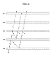
FIG. 4 is a cross-sectional view of a path of light generated from the organic light emitting element ofFIG. 1 to the outside. - In general, at least one of the hole injection electrode and the electron injection electrode of the OLED display can reflect light generated from an organic light emission layer as well as from an external source.
- Therefore, the OLED display has problems in that expression of a black color and contrast can be deteriorated due to reflection of external light when the OLED display is used in a bright place.
- In order to solve the problems, a polarizing plate and a retardation plate are disposed for suppressing reflection of the external light. However, when the external light is suppressed by the polarizing plate and the retardation plate, a large amount of light generated from the organic emission layer can also be lost.
- Embodiments of the present invention will be described more fully hereinafter with reference to the accompanying drawings, in which exemplary embodiments of the invention are shown.
- In addition, the size and thickness of each configuration shown in the drawings are not limited thereto.
- In order to describe embodiments of the present invention more clearly, parts that are not related to the description will be omitted from the drawings, and the same symbols will be given to similar parts throughout the specification. In the drawings, the thickness of layers, films, panels, regions, etc., are exaggerated for clarity. Like reference numerals designate like elements throughout the specification.
- It will be understood that when an element such as a layer, film, region, or substrate is referred to as being "on" another element, it can be directly on the other element or intervening elements may also be present. In contrast, when an element is referred to as being "directly on" another element, there are no intervening elements present.
- As shown in
FIG. 1 , an organic light emitting diode (OLED) display 100 according to an exemplary embodiment of the present invention includes a driving circuit (DC), an organic light emitting element L1, a cholesteric liquid crystal (CLC)layer 584, atranslucent metal layer 583, aretardation plate 582, and a polarizingplate 581. - The
CLC layer 584, thetranslucent metal layer 583, theretardation plate 582, and the polarizingplate 581 are substantially disposed on the organic light emitting element L1. - The DC and the organic light emitting element L1 may be formed on a
first substrate 51. In one embodiment, thefirst substrate 51 includes asubstrate member 511, the DC formed on thesubstrate member 511, and the organic light emitting element L1 formed on the DC. - In one embodiment, the DC has a circuit structure of
FIG. 2 . As shown inFIG. 2 , the DC may include at least two thin film transistors (TFTs) T1 and T2 and at least one storage capacitor C1. The TFT basically includes a switching transistor T1 and a driving transistor T2. - The switching transistor T1 is connected to a scan line SL1 and a data line DL1, and the scan line SL1 transmits a data voltage to the driving transistor T2. Here, the data voltage is input to the data line DL1 according to a switching voltage input to the scan line SL1. The storage capacitor C1 is connected to the switching transistor T1 and a power source line VDD, and stores a voltage difference of a voltage transmitted from the switching transistor T1 and a voltage supplied to the power source line VDD.
- The driving transistor T2 is connected to the power source line VDD and the storage capacitor C1 and supplies an output current IOELD, which corresponds to a square of a difference between a voltage stored in the storage capacitor C1 and a threshold voltage, to the organic light emitting element L1, and the organic light emitting element L1 emits light by the output current IOLED.
- Referring back to
FIG. 1 , the driving transistor T2 includes asource electrode 533, adrain electrode 532, and agate electrode 531. - In one embodiment, the organic light emitting element L1 includes a
first electrode 544, anorganic emission layer 545 formed on thefirst electrode 544, and asecond electrode 546 formed on theorganic emission layer 545. In one embodiment, thefirst electrode 544 is an anode and thesecond electrode 546 is a cathode. In another embodiment, thefirst electrode 544 may be a cathode and thesecond electrode 546 may be an anode. - The
first electrode 544 of the organic light emitting element L1 is connected to thedrain electrode 532 of the driving transistor T2. - Configurations of the DC and the organic light emitting element L1 are not limited to the above-described configurations, and can be variously changed with a disclosed configuration that can be easily realized by a person skilled in the art.
- The
CLC layer 584 may be formed on thesecond electrode 546 of the organic light emitting element L1. - In one embodiment, CLC has a layered structure like a smectic liquid crystal, but molecules of a longitudinal axis are arranged in parallel like a nematic liquid crystal. In one embodiment, thin and long molecules are arranged in substantially parallel in a longitudinal direction in one plane and move to a direction that is substantially perpendicular to the corresponding surface so that the alignment direction of the molecule axis has a structure that is curved in a helical shape. Therefore, the entire liquid crystal layer may have a helical structure. Accordingly, the CLC may have characteristics such as optical rotary power, selective light scattering, circular polarization, and dichroism.
- Therefore, the
CLD layer 584 can selectively transmit or reflect circularly polarized light. For example, theCLC layer 584 can transmit right circularly polarized light and reflect left circularly polarized light. - The
translucent metal layer 583 partially transmits light and partially reflects light. The amount and ratio of transmitted light and the amount and ratio of reflected light can be controlled by adjusting the thickness of thetranslucent metal layer 583. In one embodiment, thetranslucent metal layer 583 typically has a thickness of less than about 300Å, and the thickness is about 2 times the skin depth. The skin depth denotes an index that indicates how deeply a signal flows from the surface according to a frequency, and it is changed in accordance with conductivity of a metal layer. - The
retardation plate 582 changes the phase of the transmitted light. In one embodiment, a 1/4 wavelength plate is used as theretardation plate 582, and linear polarization is changed to circular polarization by theretardation plate 582. - The polarizing
plate 581 performs linear polarization on light. In one embodiment, the polarizingplate 581 transmits light that matches a polarizing axis of the polarizingplate 581, and absorbs light that does not match the polarizing axis. That is, when the light passes through the polarizingplate 581, the light is linearly polarized toward the polarizing axis of the polarizingplate 581. In addition, luminance is reduced as much as the amount of light lost by the polarizingplate 581. - In one embodiment, the linearly polarized light formed through the polarizing
plate 581 passes through theretardation plate 582 again, and the linearly polarized light becomes circularly polarized light to the right side (hereinafter referred to as right-circularly polarized) due to alignment of the polarizingplate 581 and theretardation plate 582. - On the other hand, when the right-circularly polarized light is passed through the
retardation plate 582, it becomes linearly polarized light in the same (or substantially the same) direction as the polarizing axis of thepolarizing plate 581. That is, the right-circularly polarized light becomes the linearly polarized light through theretardation plate 582, and this linearly polarized light can pass through the polarizingplate 581. - However, when the left-circularly polarized light passes through the
retardation plate 582, it becomes the linearly polarized light in a direction that crosses the polarizing axis of thepolarizing plate 581. This linearly polarized light cannot be passed thepolarization plate 581 and it is absorbed. - In one embodiment, the
CLC layer 584 passes circularly polarized light that is in the same (or substantially the same) direction as the circularly polarized light that is formed by being sequentially passed through thepolarizing plate 581 and theretardation plate 582, and reflects circularly polarized light of a different direction. In one embodiment, theCLC layer 584 passes the right-circularly polarized light and reflects the left-circularly polarized light. However, the present invention is not limited thereto. TheCLC layer 584 may pass the left-circularly polarized light and reflect the right-circularly polarized light, and lateral sides of theCLC layer 584 can respectively and selectively transmit or reflect light. - A
second substrate 52 covers thefirst substrate 51 where the organic light emitting element L1 and the DC are formed. In addition, thesecond substrate 52 also covers theCLC layer 584, thetranslucent metal layer 583, theretardation plate 582, and thepolarizing plate 581 that are sequentially formed on the organic light emitting element L1. However, the present invention is not limited thereto. TheCLC layer 584, thetranslucent metal layer 583, theretardation plate 582, and thepolarizing plate 581 may be formed on thesecond substrate 52. - Although it is not shown in the drawings, the
OLED display 100 may further include an adhesive layer interposed between thesecond electrode 546 and theCLC layer 584 on the organic light emitting element L1. - With this configuration, the
OLED display 100 can effectively suppress external light reflection and minimize light loss when light generated from the organic emission layer (545 ofFIG. 1 ) is emitted to the outside. - In addition, the
OLED display 100 can improve black color expression and contrast. That is, display characteristics of theOLED display 100 can be improved. - In addition, the
OLED display 100 can have a mirror effect by thetranslucent metal layer 583 when theorganic emission layer 545 does not emit light. - Further, the
OLED display 100 can have reduced power consumption and an increased life-span. - Hereinafter, external light suppression in the
OLED display 100 will be described with reference toFIG. 3 . - First, the external light passes through the
polarizing plate 581 and becomes linearly polarized, and the linearly polarized light passes through theretardation plate 582 and becomes right-circularly polarized light. The right-circularly polarized light partially passes through thetranslucent metal layer 583, and the rest of the right-circularly polarized light that has not passed through thetranslucent metal layer 583 is reflected by thetranslucent metal layer 583 and moves toward theretardation plate 582. Here, when the right-circularly polarized light is reflected by thetranslucent metal layer 583, the phase of the right-circularly polarized light is twisted by 180 degrees (or about 180 degrees) so that it is changed to left-circularly polarized light. - The light reflected by the
translucent metal layer 583 and changed to the left-circularly polarized light passes through theretardation plate 582 and becomes linearly polarized light in a direction that crosses the polarizing axis of thepolarizing plate 581 so that it is absorbed. - Therefore, the
OLED display 100 suppresses reflection of external light by as much as the amount of external light that is primarily reflected by thetranslucent metal layer 583. - The right-circularly polarized light having passed through the
translucent metal layer 583 passes through theCLC layer 584, and is then reflected by the second electrode (546 ofFIG. 1 ) or the first electrode (544 ofFIG. 1 ) of the organic light emitting element (L1 ofFIG. 1 ). In this instance, the right-circularly polarized light is changed to left-circularly polarized light and moves back to theCLC layer 584. The left-circularly polarized light is reflected by theCLC layer 584 and moves back to thesecond electrode 546. At this time, the phase of the left-circularly polarized light is not changed. The left-circularly polarized light is iteratively reflected by thesecond electrode 546 or thefirst electrode 544 and changed back to the right-circularly polarized light. After passing through theCLC layer 584, a part of the right-circularly polarized light is reflected by thetranslucent metal layer 583 and moves back to theCLC layer 584, and another part of the right-circularly polarized light passes through thetranslucent metal layer 583. Light reflected by thetranslucent metal layer 583 is gradually eliminated by repeating reflection and phase shift. - Therefore, the
OLED display 100 can suppress external light by as much as the amount of light that is secondarily reflected by thetranslucent metal layer 583. The right-circularly polarized light having passed through thetranslucent metal layer 583 passes through theretardation plate 582 and is changed to linearly polarized light, and the linearly polarized light is emitted outside through thepolarizing plate 581. - As described, the
OLED display 100 eliminates a large amount of external light by repeating reflecting and phase shift through thetranslucent metal layer 583 and theCLC layer 584 so that a part of the external light is reflected and emitted outside. - Therefore, the
OLED display 100 can effectively suppress external light reflection and prevent deterioration of image quality. - Hereinafter, a process in which light generated from the organic light emitting element L1 of the
OLED display 100 is emitted outside will be described with reference toFIG. 4 . - First, light generated from the organic emission layer (545 of
FIG. 1 ) passes through thesecond electrode 546 and moves to theCLC layer 584. At this time, the light includes right-circularly polarized light and left-circularly polarized light, and the right-circularly polarized light passes through theCLC layer 584 and the left-circularly polarized light is reflected by theLCL layer 584 and moves back to thesecond electrode 546. - A part of the right-circularly polarized light passed through the
LCL layer 584 is reflected by thetranslucent metal layer 583 and moves to theCLC layer 584, and the other part of the right-circularly polarized light passes through thetranslucent metal layer 583. - The right-circularly polarized light having passed through the
translucent metal layer 583 passes through theretardation plate 582 and becomes linearly polarized light, and the linearly polarized light passes through thepolarizing plate 581 and is emitted outside. Oh the other hand, the right-circularly polarized light reflected by thetranslucent metal layer 583 is changed to left-circularly polarized light and reflected by theCLC layer 584 again. - A part of the left-circularly polarized light that is reflected by the
CLC layer 584 again becomes linearly polarized light in a direction that crosses the polarizing axis of thepolarizing plate 582 while passing through thetranslucent metal layer 583 and theretardation plate 582, and the linearly polarized light is absorbed. In addition, the other part of the left-circularly polarized light that is reflected by theCLC layer 584 again is reflected by thetranslucent metal layer 583 again, and is gradually eliminated by repeating reflection and phase shift. - Left-circularly polarized light that is generated from the
organic emission layer 545, passes through thesecond electrode 546, and moves to theCLC layer 584 is changed to right-circularly polarized light while being reflected by theCLC layer 584 and is reflected by thesecond electrode 546 or thefirst electrode 544 again and passes through theCLC layer 584. The next process is the same or substantially the same as that described above. - According to at least one embodiment, the
organic emission layer 545 can minimize light loss in the process of emitting light generated from theorganic emission layer 545 to the outside. In addition, theOLED display 100 can provide a mirror effect by thetranslucent metal layer 583 when theorganic emission layer 545 does not emit light.
Claims (10)
- An organic light emitting diode (OLED) display device, comprising:a first substrate;an organic light emitting element formed over the first substrate and comprising first and second electrodes and an organic emission layer interposed between the first and second electrodes;a driving circuit formed over the substrate and configured to drive the organic light emitting element;a cholesteric liquid crystal (CLC) layer formed over the organic light emitting element and configured to selectively transmit or reflect circularly polarized light in accordance with a rotational direction of the circularly polarized light;a translucent layer formed on the CLC layer and configured to partially transmit and partially reflect incoming light;a retardation plate formed on the translucent metal layer and configured to input a first one of linearly polarized light and circularly polarized light, and to output a remaining one of linearly polarized light and circularly polarized light; anda polarizing plate formed on the retardation plate and configured to transmit a portion of incoming light that matches a polarizing axis of the polarizing plate, and to absorb the remaining incoming light that does not match the polarizing axis thereof.
- The OLED display device of claim 1, further comprising a second substrate formed on the polarizing plate.
- The OLED display device of claim 1, further comprising a second substrate formed between the CLC layer and the organic light emitting element.
- The OLED display device of one of the preceding claims, further comprising an adhesive layer interposed between the second electrode and the CLC layer.
- The OLED display device of one of the preceding claims, wherein the translucent layer is formed of metal.
- The OLED display device of one of the preceding claims, wherein the translucent layer has a thickness about 300Å.
- The OLED display device of one of the preceding claims, wherein the thickness of the translucent layer is about twice the skin depth, wherein the skin depth denotes an index that indicates how deeply a signal flows into the translucent layer according to a frequency.
- The OLED display device of one of the preceding claims, wherein the polarizing plate is configured to receive external light and output first linearly polarized light; the retardation plate is configured to convert the first linearly polarized light into first circularly polarized light; the translucent layer is configured to transmit a portion of the first circularly polarized light and reflect the remaining polarized light into a second circularly polarized light toward the retardation plate, the second circularly polarized light being 180 degrees different in phase from the first circularly polarized light; wherein the cholesteric liquid crystal (CLC) layer is configured to transmit the portion of the first circularly polarized light; and wherein at least one of the first and second electrodes is configured to reflect the portion of the first circularly polarized light toward the CLC layer.
- The OLED display device of claim 8, wherein the retardation plate is further configured to convert the second circularly polarized light into a second linearly polarized light, and
wherein the polarizing plate is further configured to absorb the second linearly polarized light. - The OLED display device of one of the claims 8 or 9, wherein at least one of the first and the second electrodes is configured to reflect the second circularly polarized light into a third circularly polarized light which is the same in phase as the first circularly polarized light,
wherein the CLC layer is further configured to transmit the third circularly polarized light, and
wherein the translucent layer is further configured to transmit a portion of the third circularly polarized light and reflect the remaining portion of the third circularly polarized light toward the CLC layer.
Applications Claiming Priority (2)
| Application Number | Priority Date | Filing Date | Title |
|---|---|---|---|
| US8386608P | 2008-07-25 | 2008-07-25 | |
| US12/508,426 US8058783B2 (en) | 2008-07-25 | 2009-07-23 | Organic light emitting diode display for suppressing reflection of external light |
Publications (2)
| Publication Number | Publication Date |
|---|---|
| EP2148381A1 true EP2148381A1 (en) | 2010-01-27 |
| EP2148381B1 EP2148381B1 (en) | 2015-01-14 |
Family
ID=41170018
Family Applications (1)
| Application Number | Title | Priority Date | Filing Date |
|---|---|---|---|
| EP09166444.1A Active EP2148381B1 (en) | 2008-07-25 | 2009-07-27 | Organic light emitting diode display |
Country Status (3)
| Country | Link |
|---|---|
| US (1) | US8058783B2 (en) |
| EP (1) | EP2148381B1 (en) |
| KR (1) | KR101094297B1 (en) |
Cited By (3)
| Publication number | Priority date | Publication date | Assignee | Title |
|---|---|---|---|---|
| EP2963505A1 (en) * | 2014-07-04 | 2016-01-06 | The Swatch Group Research and Development Ltd. | Display assembly including two stacked display devices |
| EP2963506A1 (en) * | 2014-07-04 | 2016-01-06 | The Swatch Group Research and Development Ltd. | Display assembly including two stacked display devices |
| CN106098962A (en) * | 2016-07-08 | 2016-11-09 | 京东方科技集团股份有限公司 | Polarization optics assembly, OLED and preparation method, display device |
Families Citing this family (13)
| Publication number | Priority date | Publication date | Assignee | Title |
|---|---|---|---|---|
| KR100995067B1 (en) * | 2009-01-21 | 2010-11-18 | 삼성모바일디스플레이주식회사 | Organic light emitting diode display |
| KR101244706B1 (en) * | 2009-12-01 | 2013-03-18 | 삼성디스플레이 주식회사 | Organic light emitting diode display |
| KR101699911B1 (en) * | 2010-04-05 | 2017-01-26 | 삼성디스플레이 주식회사 | Organic light emitting diode display |
| KR101784994B1 (en) * | 2011-03-31 | 2017-10-13 | 삼성디스플레이 주식회사 | Organic light emitting diode display and manufacturing method thereof |
| CN102354730B (en) * | 2011-08-29 | 2013-11-06 | 信利半导体有限公司 | OLED (Optical Light Emitting Device) illuminating device and manufacture method thereof |
| KR101908501B1 (en) * | 2011-12-07 | 2018-10-17 | 엘지디스플레이 주식회사 | Integrated Touch Screen With Organic Emitting Display Device and Method for Manufacturing the Same |
| CN103367388B (en) * | 2012-03-30 | 2016-08-03 | 群康科技(深圳)有限公司 | Organic light emitting diode display |
| TW201340781A (en) * | 2012-03-30 | 2013-10-01 | Innocom Tech Shenzhen Co Ltd | Organic light emitting diode display |
| TWI599082B (en) | 2012-10-09 | 2017-09-11 | 財團法人工業技術研究院 | Brightness enhanced self-emission type display |
| CN105264684B (en) | 2013-06-06 | 2018-01-16 | 3M创新有限公司 | Antireflection OLED is constructed |
| KR102111502B1 (en) * | 2013-12-30 | 2020-05-15 | 엘지디스플레이 주식회사 | Organic light emitting diode display device |
| KR101707944B1 (en) | 2015-06-26 | 2017-02-17 | 진우석 | Steel grating manufacturing method having l bending embossing type bearing bar |
| KR20170022047A (en) * | 2015-08-19 | 2017-03-02 | 삼성전자주식회사 | Self-luminous display panel and display apparatus having the same |
Citations (3)
| Publication number | Priority date | Publication date | Assignee | Title |
|---|---|---|---|---|
| JP2004361774A (en) * | 2003-06-06 | 2004-12-24 | Sumitomo Chem Co Ltd | Flexible display |
| US20070085476A1 (en) * | 2005-10-18 | 2007-04-19 | Semiconductor Energy Laboratory Co., Ltd. | Display device and electronic apparatus |
| GB2437553A (en) * | 2006-04-28 | 2007-10-31 | Sharp Kk | Optical system with two spaced apart partial reflectors for display |
Family Cites Families (41)
| Publication number | Priority date | Publication date | Assignee | Title |
|---|---|---|---|---|
| JP3006306B2 (en) | 1992-09-16 | 2000-02-07 | インターナショナル・ビジネス・マシーンズ・コーポレイション | Optical film and liquid crystal display device using the optical film |
| KR960003477B1 (en) | 1992-12-07 | 1996-03-14 | 엘지전자주식회사 | Liquid crystal display device |
| JPH10115826A (en) * | 1996-08-23 | 1998-05-06 | Seiko Epson Corp | Display element and electronic equipment using the same |
| JP2003121835A (en) | 1998-03-03 | 2003-04-23 | Citizen Watch Co Ltd | Liquid crystal display device |
| JP3405546B2 (en) * | 1998-03-03 | 2003-05-12 | シチズン時計株式会社 | Liquid crystal display |
| JP2000019323A (en) | 1998-06-30 | 2000-01-21 | Nippon Mitsubishi Oil Corp | Color reflection type polarizing plate |
| JP2001035653A (en) | 1999-07-21 | 2001-02-09 | Nec Corp | Organic el panel and its filter |
| US6624936B2 (en) * | 2000-05-11 | 2003-09-23 | 3M Innovative Properties Company | Color-compensated information displays |
| JP2001357979A (en) | 2000-06-15 | 2001-12-26 | Toshiba Corp | El element |
| KR20020003428A (en) | 2000-06-30 | 2002-01-12 | 권현옥 | Display picture with mirror |
| JP4053260B2 (en) | 2000-10-18 | 2008-02-27 | シャープ株式会社 | Organic electroluminescence display element |
| JP4011292B2 (en) * | 2001-01-15 | 2007-11-21 | 株式会社日立製作所 | LIGHT EMITTING ELEMENT AND DISPLAY DEVICE |
| US6532111B2 (en) * | 2001-03-05 | 2003-03-11 | Eastman Kodak Company | Wire grid polarizer |
| KR100827962B1 (en) * | 2001-11-08 | 2008-05-08 | 엘지디스플레이 주식회사 | liquid crystal display devices and manufacturing method of the same |
| JP3748406B2 (en) * | 2001-12-18 | 2006-02-22 | 株式会社日立製作所 | Display device |
| JP4036322B2 (en) | 2002-03-25 | 2008-01-23 | 日東電工株式会社 | Optical film, illumination device using the same, and image display device |
| JP2003315548A (en) | 2002-04-24 | 2003-11-06 | Nitto Denko Corp | Optical element, surface light source device, and liquid crystal display |
| JP4027164B2 (en) * | 2002-06-21 | 2007-12-26 | 株式会社日立製作所 | Display device |
| JP4085846B2 (en) | 2002-06-24 | 2008-05-14 | セイコーエプソン株式会社 | Display device and electronic apparatus equipped with the same |
| JP2004070094A (en) | 2002-08-08 | 2004-03-04 | Fujitsu Kasei Kk | Contrast increasing device |
| JP2004219825A (en) | 2003-01-16 | 2004-08-05 | Nippon Zeon Co Ltd | Optical laminate body, optical element, and optical product |
| JP4676678B2 (en) | 2003-03-07 | 2011-04-27 | 日東電工株式会社 | High brightness polarizing plate |
| JP3852931B2 (en) | 2003-03-26 | 2006-12-06 | 株式会社東芝 | Luminescent display device |
| KR100552960B1 (en) | 2003-08-12 | 2006-02-15 | 삼성에스디아이 주식회사 | Organic Electro Luminescence Display having a Reflection Type Polarizer |
| KR100518408B1 (en) | 2003-08-22 | 2005-09-29 | 엘지.필립스 엘시디 주식회사 | Dual liquid crystal display using of dual front light |
| JP2005084506A (en) | 2003-09-10 | 2005-03-31 | Sumitomo Chemical Co Ltd | Polarizing film, its manufacturing method, polarizing plate, and optical laminate |
| JP2005108540A (en) | 2003-09-29 | 2005-04-21 | Sanyo Electric Co Ltd | Self-luminous display panel |
| EP1677274A1 (en) * | 2003-10-24 | 2006-07-05 | Toshiba Matsushita Display Technology Co., Ltd. | Display |
| KR100606778B1 (en) | 2004-05-17 | 2006-08-01 | 엘지전자 주식회사 | Image display device |
| TWI252716B (en) * | 2004-12-30 | 2006-04-01 | Ind Tech Res Inst | Organic LED with brightness enhancer |
| JP2006343553A (en) | 2005-06-09 | 2006-12-21 | Citizen Watch Co Ltd | Liquid crystal apparatus |
| JP4046743B2 (en) * | 2005-07-26 | 2008-02-13 | シャープ株式会社 | Reflective display device and manufacturing method thereof |
| KR100714015B1 (en) | 2005-12-13 | 2007-05-04 | 삼성에스디아이 주식회사 | Organic luminescence display device |
| JP2007173084A (en) * | 2005-12-22 | 2007-07-05 | Canon Inc | Light-emitting element |
| JP4764230B2 (en) * | 2006-03-31 | 2011-08-31 | キヤノン株式会社 | Display device |
| TW200821681A (en) * | 2006-11-02 | 2008-05-16 | Wistron Optronics Corp | Back light unit |
| US7655898B2 (en) * | 2006-11-30 | 2010-02-02 | Cambridge Research & Instrumentation, Inc. | Optical filter assembly with selectable bandwidth and rejection |
| KR100829750B1 (en) * | 2006-12-06 | 2008-05-15 | 삼성에스디아이 주식회사 | Organic light emitting display apparatus |
| KR100846593B1 (en) | 2006-12-28 | 2008-07-16 | 삼성에스디아이 주식회사 | Organic light emitting device therewith |
| KR101463024B1 (en) | 2007-02-15 | 2014-11-18 | 엘지디스플레이 주식회사 | Flat panel display device |
| KR100834951B1 (en) | 2007-03-22 | 2008-06-09 | 이창희 | Mirror with display |
-
2009
- 2009-07-23 US US12/508,426 patent/US8058783B2/en active Active
- 2009-07-27 KR KR1020090068560A patent/KR101094297B1/en active IP Right Grant
- 2009-07-27 EP EP09166444.1A patent/EP2148381B1/en active Active
Patent Citations (3)
| Publication number | Priority date | Publication date | Assignee | Title |
|---|---|---|---|---|
| JP2004361774A (en) * | 2003-06-06 | 2004-12-24 | Sumitomo Chem Co Ltd | Flexible display |
| US20070085476A1 (en) * | 2005-10-18 | 2007-04-19 | Semiconductor Energy Laboratory Co., Ltd. | Display device and electronic apparatus |
| GB2437553A (en) * | 2006-04-28 | 2007-10-31 | Sharp Kk | Optical system with two spaced apart partial reflectors for display |
Cited By (3)
| Publication number | Priority date | Publication date | Assignee | Title |
|---|---|---|---|---|
| EP2963505A1 (en) * | 2014-07-04 | 2016-01-06 | The Swatch Group Research and Development Ltd. | Display assembly including two stacked display devices |
| EP2963506A1 (en) * | 2014-07-04 | 2016-01-06 | The Swatch Group Research and Development Ltd. | Display assembly including two stacked display devices |
| CN106098962A (en) * | 2016-07-08 | 2016-11-09 | 京东方科技集团股份有限公司 | Polarization optics assembly, OLED and preparation method, display device |
Also Published As
| Publication number | Publication date |
|---|---|
| US8058783B2 (en) | 2011-11-15 |
| EP2148381B1 (en) | 2015-01-14 |
| KR20100011962A (en) | 2010-02-03 |
| KR101094297B1 (en) | 2011-12-19 |
| US20100019667A1 (en) | 2010-01-28 |
Similar Documents
| Publication | Publication Date | Title |
|---|---|---|
| EP2148381B1 (en) | Organic light emitting diode display | |
| US8148894B2 (en) | Organic light emitting diode display | |
| US20100177265A1 (en) | Organic light emitting diode display with a mirror function | |
| EP2302682B1 (en) | High contrast organic light emitting diode display | |
| US8981349B2 (en) | Organic light emitting diode display | |
| US8169386B2 (en) | Organic light emitting diode display | |
| US8198802B2 (en) | Organic light emitting diode display for suppressing reflection of external light | |
| TWI570455B (en) | Display device | |
| KR100982312B1 (en) | Organic light emitting diode display | |
| US20140346494A1 (en) | Optical unit and organic light emitting diode display having the same | |
| KR100982313B1 (en) | Organic light emitting diode display | |
| KR101107175B1 (en) | Organic light emitting diode display | |
| KR101971146B1 (en) | Organic light emitting display device for improving ambient contrast ratio and suppressing emission loss | |
| KR102111502B1 (en) | Organic light emitting diode display device |
Legal Events
| Date | Code | Title | Description |
|---|---|---|---|
| PUAI | Public reference made under article 153(3) epc to a published international application that has entered the european phase |
Free format text: ORIGINAL CODE: 0009012 |
|
| 17P | Request for examination filed |
Effective date: 20090727 |
|
| AK | Designated contracting states |
Kind code of ref document: A1 Designated state(s): AT BE BG CH CY CZ DE DK EE ES FI FR GB GR HR HU IE IS IT LI LT LU LV MC MK MT NL NO PL PT RO SE SI SK SM TR |
|
| AX | Request for extension of the european patent |
Extension state: AL BA RS |
|
| RAP1 | Party data changed (applicant data changed or rights of an application transferred) |
Owner name: SAMSUNG DISPLAY CO., LTD. |
|
| GRAP | Despatch of communication of intention to grant a patent |
Free format text: ORIGINAL CODE: EPIDOSNIGR1 |
|
| INTG | Intention to grant announced |
Effective date: 20140917 |
|
| GRAS | Grant fee paid |
Free format text: ORIGINAL CODE: EPIDOSNIGR3 |
|
| GRAA | (expected) grant |
Free format text: ORIGINAL CODE: 0009210 |
|
| AK | Designated contracting states |
Kind code of ref document: B1 Designated state(s): AT BE BG CH CY CZ DE DK EE ES FI FR GB GR HR HU IE IS IT LI LT LU LV MC MK MT NL NO PL PT RO SE SI SK SM TR |
|
| REG | Reference to a national code |
Ref country code: GB Ref legal event code: FG4D |
|
| REG | Reference to a national code |
Ref country code: CH Ref legal event code: EP |
|
| REG | Reference to a national code |
Ref country code: IE Ref legal event code: FG4D |
|
| REG | Reference to a national code |
Ref country code: AT Ref legal event code: REF Ref document number: 707438 Country of ref document: AT Kind code of ref document: T Effective date: 20150215 |
|
| REG | Reference to a national code |
Ref country code: DE Ref legal event code: R096 Ref document number: 602009028931 Country of ref document: DE Effective date: 20150305 |
|
| REG | Reference to a national code |
Ref country code: NL Ref legal event code: VDEP Effective date: 20150114 |
|
| REG | Reference to a national code |
Ref country code: AT Ref legal event code: MK05 Ref document number: 707438 Country of ref document: AT Kind code of ref document: T Effective date: 20150114 |
|
| REG | Reference to a national code |
Ref country code: LT Ref legal event code: MG4D |
|
| PG25 | Lapsed in a contracting state [announced via postgrant information from national office to epo] |
Ref country code: LT Free format text: LAPSE BECAUSE OF FAILURE TO SUBMIT A TRANSLATION OF THE DESCRIPTION OR TO PAY THE FEE WITHIN THE PRESCRIBED TIME-LIMIT Effective date: 20150114 Ref country code: FI Free format text: LAPSE BECAUSE OF FAILURE TO SUBMIT A TRANSLATION OF THE DESCRIPTION OR TO PAY THE FEE WITHIN THE PRESCRIBED TIME-LIMIT Effective date: 20150114 Ref country code: NO Free format text: LAPSE BECAUSE OF FAILURE TO SUBMIT A TRANSLATION OF THE DESCRIPTION OR TO PAY THE FEE WITHIN THE PRESCRIBED TIME-LIMIT Effective date: 20150414 Ref country code: HR Free format text: LAPSE BECAUSE OF FAILURE TO SUBMIT A TRANSLATION OF THE DESCRIPTION OR TO PAY THE FEE WITHIN THE PRESCRIBED TIME-LIMIT Effective date: 20150114 Ref country code: ES Free format text: LAPSE BECAUSE OF FAILURE TO SUBMIT A TRANSLATION OF THE DESCRIPTION OR TO PAY THE FEE WITHIN THE PRESCRIBED TIME-LIMIT Effective date: 20150114 Ref country code: SE Free format text: LAPSE BECAUSE OF FAILURE TO SUBMIT A TRANSLATION OF THE DESCRIPTION OR TO PAY THE FEE WITHIN THE PRESCRIBED TIME-LIMIT Effective date: 20150114 Ref country code: BG Free format text: LAPSE BECAUSE OF FAILURE TO SUBMIT A TRANSLATION OF THE DESCRIPTION OR TO PAY THE FEE WITHIN THE PRESCRIBED TIME-LIMIT Effective date: 20150414 |
|
| PG25 | Lapsed in a contracting state [announced via postgrant information from national office to epo] |
Ref country code: NL Free format text: LAPSE BECAUSE OF FAILURE TO SUBMIT A TRANSLATION OF THE DESCRIPTION OR TO PAY THE FEE WITHIN THE PRESCRIBED TIME-LIMIT Effective date: 20150114 Ref country code: IS Free format text: LAPSE BECAUSE OF FAILURE TO SUBMIT A TRANSLATION OF THE DESCRIPTION OR TO PAY THE FEE WITHIN THE PRESCRIBED TIME-LIMIT Effective date: 20150514 Ref country code: LV Free format text: LAPSE BECAUSE OF FAILURE TO SUBMIT A TRANSLATION OF THE DESCRIPTION OR TO PAY THE FEE WITHIN THE PRESCRIBED TIME-LIMIT Effective date: 20150114 Ref country code: PL Free format text: LAPSE BECAUSE OF FAILURE TO SUBMIT A TRANSLATION OF THE DESCRIPTION OR TO PAY THE FEE WITHIN THE PRESCRIBED TIME-LIMIT Effective date: 20150114 Ref country code: AT Free format text: LAPSE BECAUSE OF FAILURE TO SUBMIT A TRANSLATION OF THE DESCRIPTION OR TO PAY THE FEE WITHIN THE PRESCRIBED TIME-LIMIT Effective date: 20150114 Ref country code: GR Free format text: LAPSE BECAUSE OF FAILURE TO SUBMIT A TRANSLATION OF THE DESCRIPTION OR TO PAY THE FEE WITHIN THE PRESCRIBED TIME-LIMIT Effective date: 20150415 |
|
| RAP2 | Party data changed (patent owner data changed or rights of a patent transferred) |
Owner name: SAMSUNG DISPLAY CO., LTD. |
|
| REG | Reference to a national code |
Ref country code: DE Ref legal event code: R097 Ref document number: 602009028931 Country of ref document: DE |
|
| PG25 | Lapsed in a contracting state [announced via postgrant information from national office to epo] |
Ref country code: EE Free format text: LAPSE BECAUSE OF FAILURE TO SUBMIT A TRANSLATION OF THE DESCRIPTION OR TO PAY THE FEE WITHIN THE PRESCRIBED TIME-LIMIT Effective date: 20150114 Ref country code: RO Free format text: LAPSE BECAUSE OF FAILURE TO SUBMIT A TRANSLATION OF THE DESCRIPTION OR TO PAY THE FEE WITHIN THE PRESCRIBED TIME-LIMIT Effective date: 20150114 Ref country code: DK Free format text: LAPSE BECAUSE OF FAILURE TO SUBMIT A TRANSLATION OF THE DESCRIPTION OR TO PAY THE FEE WITHIN THE PRESCRIBED TIME-LIMIT Effective date: 20150114 Ref country code: SK Free format text: LAPSE BECAUSE OF FAILURE TO SUBMIT A TRANSLATION OF THE DESCRIPTION OR TO PAY THE FEE WITHIN THE PRESCRIBED TIME-LIMIT Effective date: 20150114 Ref country code: CZ Free format text: LAPSE BECAUSE OF FAILURE TO SUBMIT A TRANSLATION OF THE DESCRIPTION OR TO PAY THE FEE WITHIN THE PRESCRIBED TIME-LIMIT Effective date: 20150114 |
|
| PLBE | No opposition filed within time limit |
Free format text: ORIGINAL CODE: 0009261 |
|
| STAA | Information on the status of an ep patent application or granted ep patent |
Free format text: STATUS: NO OPPOSITION FILED WITHIN TIME LIMIT |
|
| 26N | No opposition filed |
Effective date: 20151015 |
|
| PG25 | Lapsed in a contracting state [announced via postgrant information from national office to epo] |
Ref country code: IT Free format text: LAPSE BECAUSE OF FAILURE TO SUBMIT A TRANSLATION OF THE DESCRIPTION OR TO PAY THE FEE WITHIN THE PRESCRIBED TIME-LIMIT Effective date: 20150114 |
|
| PG25 | Lapsed in a contracting state [announced via postgrant information from national office to epo] |
Ref country code: MC Free format text: LAPSE BECAUSE OF FAILURE TO SUBMIT A TRANSLATION OF THE DESCRIPTION OR TO PAY THE FEE WITHIN THE PRESCRIBED TIME-LIMIT Effective date: 20150114 Ref country code: SI Free format text: LAPSE BECAUSE OF FAILURE TO SUBMIT A TRANSLATION OF THE DESCRIPTION OR TO PAY THE FEE WITHIN THE PRESCRIBED TIME-LIMIT Effective date: 20150114 |
|
| REG | Reference to a national code |
Ref country code: CH Ref legal event code: PL |
|
| PG25 | Lapsed in a contracting state [announced via postgrant information from national office to epo] |
Ref country code: LU Free format text: LAPSE BECAUSE OF FAILURE TO SUBMIT A TRANSLATION OF THE DESCRIPTION OR TO PAY THE FEE WITHIN THE PRESCRIBED TIME-LIMIT Effective date: 20150727 |
|
| REG | Reference to a national code |
Ref country code: IE Ref legal event code: MM4A |
|
| PG25 | Lapsed in a contracting state [announced via postgrant information from national office to epo] |
Ref country code: CH Free format text: LAPSE BECAUSE OF NON-PAYMENT OF DUE FEES Effective date: 20150731 Ref country code: LI Free format text: LAPSE BECAUSE OF NON-PAYMENT OF DUE FEES Effective date: 20150731 |
|
| PG25 | Lapsed in a contracting state [announced via postgrant information from national office to epo] |
Ref country code: BE Free format text: LAPSE BECAUSE OF FAILURE TO SUBMIT A TRANSLATION OF THE DESCRIPTION OR TO PAY THE FEE WITHIN THE PRESCRIBED TIME-LIMIT Effective date: 20150114 |
|
| REG | Reference to a national code |
Ref country code: FR Ref legal event code: PLFP Year of fee payment: 8 |
|
| PG25 | Lapsed in a contracting state [announced via postgrant information from national office to epo] |
Ref country code: IE Free format text: LAPSE BECAUSE OF NON-PAYMENT OF DUE FEES Effective date: 20150727 |
|
| PG25 | Lapsed in a contracting state [announced via postgrant information from national office to epo] |
Ref country code: MT Free format text: LAPSE BECAUSE OF FAILURE TO SUBMIT A TRANSLATION OF THE DESCRIPTION OR TO PAY THE FEE WITHIN THE PRESCRIBED TIME-LIMIT Effective date: 20150114 |
|
| PG25 | Lapsed in a contracting state [announced via postgrant information from national office to epo] |
Ref country code: HU Free format text: LAPSE BECAUSE OF FAILURE TO SUBMIT A TRANSLATION OF THE DESCRIPTION OR TO PAY THE FEE WITHIN THE PRESCRIBED TIME-LIMIT; INVALID AB INITIO Effective date: 20090727 Ref country code: SM Free format text: LAPSE BECAUSE OF FAILURE TO SUBMIT A TRANSLATION OF THE DESCRIPTION OR TO PAY THE FEE WITHIN THE PRESCRIBED TIME-LIMIT Effective date: 20150114 |
|
| PG25 | Lapsed in a contracting state [announced via postgrant information from national office to epo] |
Ref country code: CY Free format text: LAPSE BECAUSE OF FAILURE TO SUBMIT A TRANSLATION OF THE DESCRIPTION OR TO PAY THE FEE WITHIN THE PRESCRIBED TIME-LIMIT Effective date: 20150114 |
|
| REG | Reference to a national code |
Ref country code: FR Ref legal event code: PLFP Year of fee payment: 9 |
|
| PG25 | Lapsed in a contracting state [announced via postgrant information from national office to epo] |
Ref country code: TR Free format text: LAPSE BECAUSE OF FAILURE TO SUBMIT A TRANSLATION OF THE DESCRIPTION OR TO PAY THE FEE WITHIN THE PRESCRIBED TIME-LIMIT Effective date: 20150114 |
|
| REG | Reference to a national code |
Ref country code: FR Ref legal event code: PLFP Year of fee payment: 10 |
|
| PG25 | Lapsed in a contracting state [announced via postgrant information from national office to epo] |
Ref country code: PT Free format text: LAPSE BECAUSE OF FAILURE TO SUBMIT A TRANSLATION OF THE DESCRIPTION OR TO PAY THE FEE WITHIN THE PRESCRIBED TIME-LIMIT Effective date: 20150114 Ref country code: MK Free format text: LAPSE BECAUSE OF FAILURE TO SUBMIT A TRANSLATION OF THE DESCRIPTION OR TO PAY THE FEE WITHIN THE PRESCRIBED TIME-LIMIT Effective date: 20150114 |
|
| REG | Reference to a national code |
Ref country code: DE Ref legal event code: R079 Ref document number: 602009028931 Country of ref document: DE Free format text: PREVIOUS MAIN CLASS: H01L0051520000 Ipc: H10K0050800000 |
|
| P01 | Opt-out of the competence of the unified patent court (upc) registered |
Effective date: 20230515 |
|
| PGFP | Annual fee paid to national office [announced via postgrant information from national office to epo] |
Ref country code: FR Payment date: 20230621 Year of fee payment: 15 |
|
| PGFP | Annual fee paid to national office [announced via postgrant information from national office to epo] |
Ref country code: GB Payment date: 20230620 Year of fee payment: 15 |
|
| PGFP | Annual fee paid to national office [announced via postgrant information from national office to epo] |
Ref country code: DE Payment date: 20230620 Year of fee payment: 15 |