EP2148187A1 - Stimulation and optical display system for fluorescence detection - Google Patents
Stimulation and optical display system for fluorescence detection Download PDFInfo
- Publication number
- EP2148187A1 EP2148187A1 EP08013392A EP08013392A EP2148187A1 EP 2148187 A1 EP2148187 A1 EP 2148187A1 EP 08013392 A EP08013392 A EP 08013392A EP 08013392 A EP08013392 A EP 08013392A EP 2148187 A1 EP2148187 A1 EP 2148187A1
- Authority
- EP
- European Patent Office
- Prior art keywords
- array
- field lens
- lens array
- detection sites
- optical device
- Prior art date
- Legal status (The legal status is an assumption and is not a legal conclusion. Google has not performed a legal analysis and makes no representation as to the accuracy of the status listed.)
- Withdrawn
Links
- 230000003287 optical effect Effects 0.000 title claims abstract description 172
- 238000001917 fluorescence detection Methods 0.000 title description 21
- 230000000638 stimulation Effects 0.000 title 1
- 238000001514 detection method Methods 0.000 claims abstract description 185
- 230000005284 excitation Effects 0.000 claims abstract description 138
- 210000001747 pupil Anatomy 0.000 claims abstract description 88
- 108020004414 DNA Proteins 0.000 claims abstract description 26
- 238000012544 monitoring process Methods 0.000 claims abstract description 11
- 238000003753 real-time PCR Methods 0.000 claims abstract description 10
- 238000001816 cooling Methods 0.000 claims abstract description 6
- 238000000034 method Methods 0.000 claims abstract description 6
- 238000010438 heat treatment Methods 0.000 claims abstract description 5
- 238000003384 imaging method Methods 0.000 claims description 75
- 238000005286 illumination Methods 0.000 claims description 37
- 238000006243 chemical reaction Methods 0.000 claims description 12
- 230000004568 DNA-binding Effects 0.000 claims description 9
- 239000011541 reaction mixture Substances 0.000 claims description 9
- 230000003321 amplification Effects 0.000 claims description 6
- 238000003199 nucleic acid amplification method Methods 0.000 claims description 6
- 239000000203 mixture Substances 0.000 claims description 5
- 108091028043 Nucleic acid sequence Proteins 0.000 claims description 2
- 102000053602 DNA Human genes 0.000 abstract description 25
- 238000003752 polymerase chain reaction Methods 0.000 abstract description 17
- 239000007850 fluorescent dye Substances 0.000 description 18
- 239000000523 sample Substances 0.000 description 17
- 238000003556 assay Methods 0.000 description 9
- 239000000975 dye Substances 0.000 description 8
- 238000004458 analytical method Methods 0.000 description 7
- 238000005259 measurement Methods 0.000 description 7
- 239000000243 solution Substances 0.000 description 7
- 230000004075 alteration Effects 0.000 description 6
- 238000009396 hybridization Methods 0.000 description 6
- 239000007787 solid Substances 0.000 description 6
- 238000012408 PCR amplification Methods 0.000 description 5
- 230000000873 masking effect Effects 0.000 description 5
- 102000039446 nucleic acids Human genes 0.000 description 5
- 108020004707 nucleic acids Proteins 0.000 description 5
- 150000007523 nucleic acids Chemical class 0.000 description 5
- 238000000926 separation method Methods 0.000 description 5
- 238000002866 fluorescence resonance energy transfer Methods 0.000 description 4
- 238000002493 microarray Methods 0.000 description 4
- 230000001419 dependent effect Effects 0.000 description 3
- 238000000799 fluorescence microscopy Methods 0.000 description 3
- 239000007791 liquid phase Substances 0.000 description 3
- 238000013507 mapping Methods 0.000 description 3
- 230000005855 radiation Effects 0.000 description 3
- 230000001629 suppression Effects 0.000 description 3
- 229910052724 xenon Inorganic materials 0.000 description 3
- FHNFHKCVQCLJFQ-UHFFFAOYSA-N xenon atom Chemical compound [Xe] FHNFHKCVQCLJFQ-UHFFFAOYSA-N 0.000 description 3
- 206010010071 Coma Diseases 0.000 description 2
- 238000000018 DNA microarray Methods 0.000 description 2
- 102000004190 Enzymes Human genes 0.000 description 2
- 108090000790 Enzymes Proteins 0.000 description 2
- 238000000137 annealing Methods 0.000 description 2
- 238000003491 array Methods 0.000 description 2
- 201000009310 astigmatism Diseases 0.000 description 2
- 230000008901 benefit Effects 0.000 description 2
- 230000000903 blocking effect Effects 0.000 description 2
- 230000008859 change Effects 0.000 description 2
- 125000004122 cyclic group Chemical group 0.000 description 2
- 230000007423 decrease Effects 0.000 description 2
- 230000000694 effects Effects 0.000 description 2
- 238000002795 fluorescence method Methods 0.000 description 2
- 230000004907 flux Effects 0.000 description 2
- 239000011521 glass Substances 0.000 description 2
- 230000006872 improvement Effects 0.000 description 2
- 239000004615 ingredient Substances 0.000 description 2
- 238000004519 manufacturing process Methods 0.000 description 2
- 239000003550 marker Substances 0.000 description 2
- 238000002844 melting Methods 0.000 description 2
- 230000008018 melting Effects 0.000 description 2
- 238000002156 mixing Methods 0.000 description 2
- 238000012856 packing Methods 0.000 description 2
- 239000012071 phase Substances 0.000 description 2
- 108090000623 proteins and genes Proteins 0.000 description 2
- 102000004169 proteins and genes Human genes 0.000 description 2
- 238000011002 quantification Methods 0.000 description 2
- 230000035945 sensitivity Effects 0.000 description 2
- 239000007790 solid phase Substances 0.000 description 2
- 230000009870 specific binding Effects 0.000 description 2
- 108020004635 Complementary DNA Proteins 0.000 description 1
- 238000007702 DNA assembly Methods 0.000 description 1
- 239000003298 DNA probe Substances 0.000 description 1
- 108010076282 Factor IX Proteins 0.000 description 1
- 229910000831 Steel Inorganic materials 0.000 description 1
- 239000007864 aqueous solution Substances 0.000 description 1
- 230000027455 binding Effects 0.000 description 1
- 239000012472 biological sample Substances 0.000 description 1
- 239000000872 buffer Substances 0.000 description 1
- 238000010804 cDNA synthesis Methods 0.000 description 1
- 238000004364 calculation method Methods 0.000 description 1
- 239000002299 complementary DNA Substances 0.000 description 1
- 239000002131 composite material Substances 0.000 description 1
- 238000003271 compound fluorescence assay Methods 0.000 description 1
- 230000003247 decreasing effect Effects 0.000 description 1
- 238000004925 denaturation Methods 0.000 description 1
- 230000036425 denaturation Effects 0.000 description 1
- 230000006866 deterioration Effects 0.000 description 1
- 238000001962 electrophoresis Methods 0.000 description 1
- 230000002255 enzymatic effect Effects 0.000 description 1
- 238000002073 fluorescence micrograph Methods 0.000 description 1
- 239000000499 gel Substances 0.000 description 1
- 230000017525 heat dissipation Effects 0.000 description 1
- 238000003018 immunoassay Methods 0.000 description 1
- 230000003993 interaction Effects 0.000 description 1
- 230000002452 interceptive effect Effects 0.000 description 1
- 238000002372 labelling Methods 0.000 description 1
- 230000002045 lasting effect Effects 0.000 description 1
- 238000007403 mPCR Methods 0.000 description 1
- QSHDDOUJBYECFT-UHFFFAOYSA-N mercury Chemical compound [Hg] QSHDDOUJBYECFT-UHFFFAOYSA-N 0.000 description 1
- 229910052753 mercury Inorganic materials 0.000 description 1
- 239000002773 nucleotide Substances 0.000 description 1
- 125000003729 nucleotide group Chemical group 0.000 description 1
- 230000035515 penetration Effects 0.000 description 1
- 230000000737 periodic effect Effects 0.000 description 1
- 238000011897 real-time detection Methods 0.000 description 1
- 230000002829 reductive effect Effects 0.000 description 1
- 230000011514 reflex Effects 0.000 description 1
- 230000002441 reversible effect Effects 0.000 description 1
- 239000004065 semiconductor Substances 0.000 description 1
- 230000003595 spectral effect Effects 0.000 description 1
- 238000001228 spectrum Methods 0.000 description 1
- 239000010959 steel Substances 0.000 description 1
- 239000000126 substance Substances 0.000 description 1
- 238000012360 testing method Methods 0.000 description 1
- 238000005382 thermal cycling Methods 0.000 description 1
- 238000012546 transfer Methods 0.000 description 1
- 230000009466 transformation Effects 0.000 description 1
- WFKWXMTUELFFGS-UHFFFAOYSA-N tungsten Chemical compound [W] WFKWXMTUELFFGS-UHFFFAOYSA-N 0.000 description 1
- 229910052721 tungsten Inorganic materials 0.000 description 1
- 239000010937 tungsten Substances 0.000 description 1
- 239000002699 waste material Substances 0.000 description 1
Images


Classifications
-
- G—PHYSICS
- G02—OPTICS
- G02B—OPTICAL ELEMENTS, SYSTEMS OR APPARATUS
- G02B27/00—Optical systems or apparatus not provided for by any of the groups G02B1/00 - G02B26/00, G02B30/00
- G02B27/0018—Optical systems or apparatus not provided for by any of the groups G02B1/00 - G02B26/00, G02B30/00 with means for preventing ghost images
-
- G—PHYSICS
- G01—MEASURING; TESTING
- G01N—INVESTIGATING OR ANALYSING MATERIALS BY DETERMINING THEIR CHEMICAL OR PHYSICAL PROPERTIES
- G01N21/00—Investigating or analysing materials by the use of optical means, i.e. using sub-millimetre waves, infrared, visible or ultraviolet light
- G01N21/62—Systems in which the material investigated is excited whereby it emits light or causes a change in wavelength of the incident light
- G01N21/63—Systems in which the material investigated is excited whereby it emits light or causes a change in wavelength of the incident light optically excited
- G01N21/64—Fluorescence; Phosphorescence
- G01N21/645—Specially adapted constructive features of fluorimeters
- G01N21/6452—Individual samples arranged in a regular 2D-array, e.g. multiwell plates
-
- G—PHYSICS
- G02—OPTICS
- G02B—OPTICAL ELEMENTS, SYSTEMS OR APPARATUS
- G02B21/00—Microscopes
- G02B21/16—Microscopes adapted for ultraviolet illumination ; Fluorescence microscopes
-
- G—PHYSICS
- G02—OPTICS
- G02B—OPTICAL ELEMENTS, SYSTEMS OR APPARATUS
- G02B3/00—Simple or compound lenses
- G02B3/0006—Arrays
- G02B3/0037—Arrays characterized by the distribution or form of lenses
- G02B3/0056—Arrays characterized by the distribution or form of lenses arranged along two different directions in a plane, e.g. honeycomb arrangement of lenses
-
- G—PHYSICS
- G02—OPTICS
- G02B—OPTICAL ELEMENTS, SYSTEMS OR APPARATUS
- G02B3/00—Simple or compound lenses
- G02B3/0006—Arrays
- G02B3/0037—Arrays characterized by the distribution or form of lenses
- G02B3/0062—Stacked lens arrays, i.e. refractive surfaces arranged in at least two planes, without structurally separate optical elements in-between
-
- G—PHYSICS
- G02—OPTICS
- G02B—OPTICAL ELEMENTS, SYSTEMS OR APPARATUS
- G02B2207/00—Coding scheme for general features or characteristics of optical elements and systems of subclass G02B, but not including elements and systems which would be classified in G02B6/00 and subgroups
- G02B2207/113—Fluorescence
Definitions
- the present invention relates to the field of DNA analysis.
- the present invention relates to a device for parallel imaging of fluorescence intensities from a plurality of detection sites, and in particular the excitation and imaging optics for the fluorescence detection of fluorescence signals.
- PCR Polymerase Chain Reaction
- a thermal cycling block has one or more holding jars (wells) containing a mixture of ingredients for a reaction that yields more DNA from a starting amount of the DNA.
- the starting ingredients in an aqueous solution comprise a "seed" of the DNA, certain primary DNA, DNA elements, enzymes, and other chemicals.
- the temperature of the block is between a low extension phase of the PCR reaction of about 60 ° C, in which all DNA strands are recombined in double strands, and a higher denaturation phase of about 95 ° C, in which the DNA is denatured or in single strands split, cycled.
- a temperature program essentially doubles the DNA in each cycle, allowing for the ability to replicate substantial amounts of the DNA from a small starting amount.
- the quantitative determination of the DNA takes place with fluorescence measurements, also in real time.
- an optical device ie, a fluorescence excitation and reading device
- a fluorescence excitation and reading device that provides light of a particular wavelength to excite the fluorescent label of the assay and that is capable of detecting the fluorescent light from the marker that is incident on a marker something different wavelength is emitted to capture.
- a major problem with all such fluorescence gauges is the enormous intensity of the excitation light as compared to the fluorescent light emitted by the dye, and therefore one must ensure that the excitation beam does not strike the detector to accurately monitor the fluorescence signals.
- the beam path (light path) of the excitation light must be at least partially different from the beam path (light path) of the fluorescent light.
- the following measures are customary for this: a) A spectral separation by excitation and emission filters whose spectra do not significantly overlap. b) The use of reflected light (or epi) lighting or side lighting. In this case, no beam of the illumination light in a direction that can be detected directly (dark field). At least one reflex, elastic scattering or just the fluorescence (inelastic scattering) is needed. The measure b) is usually used as support for measure a) as the filter blockage is not perfect according to measure a).
- the first strategy is to scan the lateral distribution of detection sites, successively analyzing each detection site individually.
- the second strategy is to illuminate the entire distribution of detection sites simultaneously and image the corresponding fluorescence to a plurality of optical sensors, eg a CCD chip.
- the scanning strategy has the obvious disadvantage that either the carrier must be moved in two dimensions (see eg WO 03/069391 . DE 102 00 499 ), the detector must be moved relative to the carrier ( US 2002/159057 ), the detector must move in one dimension and the beam must move in the other dimension, or the optics must have one or two-dimensional scanning means, ie galvo mirrors.
- the main difficulty of the second strategy of illuminating the entire carrier at the same time is to ensure uniform illumination over the entire distribution of detection sites.
- each detection site is illuminated by its own light source.
- the DE 101 31 687 describes this strategy for evaluating PCR in a thermocycler having a plurality of wells using a beam splitter and an array of LEDs for illumination.
- the DE 101 55 142 describes the dark field monitoring of fluorescence signals, where the microarray is also illuminated by an array of LEDs, but no beam splitter is needed in this embodiment.
- the first possibility is the so-called epi-illumination, wherein beam splitters are used and the excitation beam and the fluorescent light share at least part of the optical system.
- the second possibility is the use of oblique lighting.
- the excitation beam is arranged in such a way that it has a certain angle to the normal of the support surface and the corresponding reflection of the excitation beam is outside the opening angle of the detection system (eg US 2002/0005493 A1 . EP 1 275 954 A2 ).
- the US 2003/0011772 A1 describes an optical apparatus for simultaneously observing a plurality of fluorescent dyes in a probe using a beam splitter.
- the DE 197 48 211 A1 discloses a system for simultaneously monitoring the fluorescence signals generated in the wells of a microtiter plate using a beam splitter, a field lens, and an array of lenses that focus the light into each well. The detection is performed by imaging the light on an array of photodiodes or on a CCD chip.
- the fluorescence light collected in this embodiment of the system is determined by the amount of dyes excited by the light cone of the focusing lens, and thus depends on the fill level of the well.
- the WO 99/60381 describes a device for simultaneously monitoring PCR reactions in a plurality of wells in a block whose temperature is cycled.
- the optical components of this device again comprise a beam splitter, a field lens, an array of lenses for the wells that focus individual light beams into each well, and a detection means that focuses the emitted light onto, for example, a CCD detector. Due to the need for an array of lenses for the wells, the size and lateral density of the individual detection sites are limited, the luminous efficacy of this arrangement is low, and there is considerable crosstalk between the individual detected wells, ie channel separation is low.
- the JP 2002014044 describes a fluorometric device for monitoring fluorescence generated in a plurality of wells.
- the optical components include a beam splitter and a lens system for illuminating the wells in common with light that is parallel to the depth direction of the wells. However, the imaging optical system compresses the light to a detection means.
- the US Pat. No. 6,498,690 B1 discloses a method of imaging assays with a lens having a telecentric lens.
- the US 6,246,525 B1 describes an imaging device for imaging a slide with a Fresnel lens.
- the EP 0 987 540 A discloses a fluorescence assay imaging apparatus having an imaging unit comprising a set of telecentric lenses.
- the EP 1 406 082 A describes a fluorescence reading device with telecentric illumination.
- the EP 1 681 555 B1 describes an improved apparatus for simultaneously monitoring fluorescence signals from a lateral distribution of detection sites, optimizing the beam path for uniform illumination and accurate detection. It comprises an imaging lens arrangement arranged to transmit fluorescence signals from the field lens to the optical sensor, and has the peculiarity that the beam path of the excitation light and the beam path of the fluorescence signals from the plurality of individual detection sites on the object side Field lens are telecentric.
- the EP 1 681 556 B1 describes a similar, further improved apparatus wherein the field lens is arranged to generate excitation light having an angle of incidence to the planar support of the array of a plurality of discrete detection locations greater than 0 °.
- the luminous efficiency can be improved to detect even smaller fluorescence signals or fluorescence signals with a better signal-to-noise ratio or better Detect resolution.
- the object of the present invention is to provide an improved apparatus for simultaneously monitoring fluorescence signals from a lateral distribution of a plurality of individual detection sites by optimizing the beam path with respect to a higher light output.
- the problem to be solved relates to improvements in the monitoring of real-time multiplex PCR in a microtiter plate format.
- the invention is directed to an optical device for imaging fluorescence signals from an array of a plurality of discrete detection sites with uniform excitation over the entire region of the array, accurate imaging of the corresponding fluorescence signals, and high luminous efficacy.
- the invention is also directed to an optical device for simultaneously analyzing a plurality of PCR amplifications in real time that take place in the wells of a microtiter plate or for imaging the fluorescence intensity of a microarray as a measure of specific target-probe interactions.
- the beam path of the excitation light and the beam path of the fluorescence signals from the plurality of individual detection sites on the object side of the field lens are telecentric, i. the optical device uses a telecentric pupil layer. More specifically, within the scope of the invention, the beam path is telecentric on the object side of the field lens and on the object side of the field lens array. On the other hand, i. between the pupil lens array and the arrangement of a plurality of individual detection sites, the beam path is no longer telecentric. Here no telecentric is needed anymore. Each detection site "sees" the same non-telecentric pupil for illumination and detection through the periodic array optics assembly. In the prior art, the detection optics are telecentric on the side of the field lens, but not on the side of the optical sensor, and the illumination optics are telecentric on the side of the field lens and also on the side of a possibly used light mixing rod.
- the invention not only allows a higher luminous efficacy to detect even smaller fluorescence signals or fluorescence signals with an improved signal-to-noise ratio or better resolution, but numerous other advantages, including a faster implementation of the fluorescence measurement.
- the prior art high-performance lamps are used with high luminance, such as xenon arc lamps to compensate for the low light output so far.
- high-power lamps not only have a high thermal power loss, which requires a complex heat dissipation or cooling, but also a relatively short life, which is usually in the order of about 500 hours.
- a change of lamp is necessary in the prior art.
- the signal gain and sensitivity improvement of the invention avoids these problems and also provides the opportunity to use weaker and thus longer lasting lamps as well as alternative light sources, eg LEDs with a longer life and reliability.
- a significant advantage of the invention is therefore the extension of the life of the light source used.
- an array of a plurality of discrete detection sites combines objects that consist of two or more spatially separated and laterally distributed detection sites.
- the detection sites may be e.g. to act wells of a microtiter plate or functionalized areas of a slide or glass slide.
- the array of a plurality of individual detection sites will be arranged uniformly, uniformly, uniformly, or in a particular grid, and each detection site will have a different content to perform a multiplex analysis.
- the planar support of the arrangement is preferably a flat solid phase.
- the planar support of the array is the face of this planar solid phase where the detection sites are located.
- the planar support of the assembly is the plane where the openings of the wells are located. The planar support of the arrangement is fixed by a holding device in order to fix each individual detection location at the desired position within the beam path.
- the term light source includes illuminants that emit light at a single frequency or at a plurality of different frequencies.
- the light source may be an array of more than one light source.
- an optical sensor is a device for converting visible light into electrical signals that can be processed by a computer.
- the optical sensor may comprise a single or multiple optical sensors.
- a preferred embodiment is an optical sensor having a plurality of optical sensors placed in a spatially distributed arrangement, preferably according to the arrangement of the plurality of individual ones Detection locations is formed.
- Preferred embodiments are semiconductor components, for example photodiodes, or in particular charge-coupled components, for example a CCD chip.
- a telecentric optic is optics with an aperture stop projected into infinity by the optical elements between the aperture stop and the object.
- the principal rays of telecentric optics in the object space are quasi-parallel.
- the term principal rays is used for all rays passing through the center of the aperture stop.
- object, object plane and object space are used to describe the planar carrier with the arrangement of a plurality of individual detection sites.
- the excitation lens arrangement and the imaging lens arrangement both have their own aperture stop.
- the telecentric optic is telecentric for the excitation beam path and the optical path for detecting the fluorescence signals on the field lens side of the array optics assembly.
- Each object point in a plane perpendicular to the optical axis corresponds to a main excitation beam and a main detection beam. Since all the main excitation beams and also all the main detection beams are quasi-parallel, good uniform lateral distribution in the object plane is ensured and the detection locations in the center of the array are comparable to those at the edge of the array.
- a telecentric optic always has a field lens.
- the field lens is a lens closest to the object (relative to an embodiment of the optical device without the array optics assembly) of all the excitation light rays and all fluorescence signals, may have one or more components, and be co-located with contributes additional optical components of the device for telecentricity in the object and / or in the image space of the device.
- the one or more components (achromat) of the field lens may themselves be lens elements that are spatially separated.
- the field lens determines the field of view of the optical device.
- a telecentric optic is furthermore preferably an optic which has a very small aperture and thus provides a high depth of focus.
- the telecentric light of such telecentric optics is quasi-parallel to the principal rays for all points across the object that are parallel to the optical axis in the object and / or imaging space. Therefore, the quality of excitation optics or imaging optics using telecentricity in object space is insensitive to the distance of a particular object point from the optics.
- the aperture of a telecentric optic is imaged into the infinite.
- the use of telecentric light also ensures good lateral homogeneity across the light beam, and the detection locations located in the center of the array are comparable to those located at the edge of the array.
- the field lens of the present invention transmits excitation light from the light source to the array of a plurality of discrete detection sites and transmits fluorescence signals from the array of a plurality of discrete detection sites to the optical sensor. This does not exclude that additional optical components are introduced into the beam path, e.g. between the light source and the field lens, between the field lens and the optical sensor or between the field lens and the arrangement of a plurality of individual detection sites (in particular an array optics arrangement according to the invention).
- the angle of incidence ⁇ is defined as the angle between the quasi-parallel principal rays of the excitation light beam and the normal of the interface, which in the context of this invention is the carrier of the device.
- the means for heating and cooling comprise any means capable of controlling and changing the temperature of the array of a plurality of individual detection sites in a cyclic manner to perform a cyclic PCR amplification of nucleic acids.
- Each PCR cycle involves several different steps: an annealing step with a lowering of the temperature, an enzymatic amplification step at relatively low temperatures together with a detection step using fluorescent dyes and a melting step at high temperatures.
- the fixture may be in thermal contact with the planar support of the array of a plurality of discrete detection sites and heated and cooled.
- an array of a plurality of individual detection sites preferably combines individual objects of an assay composed of two or more assays spatially separated to realize a parallel analysis.
- These assays may e.g. in wells of a microtiter plate or on functionalized areas of a glass slide.
- the array of a plurality of individual assays will be arranged in a uniform manner and each assay will have a different content to perform a multiplex analysis.
- each site of the array is functionalized with an oligomer having a particular sequence
- each site of the array is functionalized with e.g. Proteins that have different affinities, is functionalized.
- microtiter plates in each well, e.g. another PCR was performed.
- beam path in the present invention is used to summarize all areas that the light beam travels from the light source through at least the field lens to the array of a plurality of individual assays and from the array of a plurality of individual assays through at least the field lens to the optical sensor passes.
- the fluorescent DNA binding moieties are any fluorescent dyes or arrays of fluorescent dyes for real-time detection of amplified DNA known to those skilled in the art and which can be used to detect amplified DNA, e.g. double-stranded DNA-specific binding dyes, fluorescently-labeled hybridization probes which emit fluorescence only when bound to their target nucleic acid, TagMan probes, Molecular Beacons, single-label probes (SLP) or FRET hybridization probes.
- double-stranded DNA-specific binding dyes fluorescently-labeled hybridization probes which emit fluorescence only when bound to their target nucleic acid
- TagMan probes Molecular Beacons
- SLP single-label probes
- composition or reaction mixture capable of performing PCR reactions is within the scope of this invention Buffers, nucleotides, enzymes, primers and the fluorescence DNA binding units.
- thermocycling protocol is the protocol that specifies the chronological temperature treatment of the PCR composition, the melting and annealing temperatures, the number of cycles of amplification, and the periods of heating and cooling.
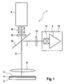
- the FIG. 1 shows a schematic representation of an embodiment of an optical device 1 for imaging fluorescence signals from a plurality of individual detection sites 2 according to the prior art, for example according to the EP 1 681 555 B1 or EP 1 681 556 B1 .
- the optical device 1 serves to simultaneously monitor and detect PCR amplifications (polymerase chain reaction amplifications) that take place in the individual wells of a microtiter plate.
- the wells of the multiwell plate thus form an arrangement of a multiplicity of individual detection sites 2.
- the optical device 1 for imaging fluorescence signals from an array of a plurality of individual detection sites 2 comprises a holding device 3 for holding a planar carrier 4 with an arrangement of a multiplicity of individual detection sites 2, at least one light source 5 for emitting light having at least one excitation frequency, an optical sensor 6 arranged to receive fluorescence signals 7 from the array of a plurality of individual detection sites 2 and adapted to generate computer readable primary data, a field lens 8 arranged to transmit excitation light 9 from the light source 5 to the array of a plurality of individual detection sites 2 and fluorescence signals 7 from the array of a plurality of individual detection sites 2 to the optical sensor 6, an excitation lens array 10 thus arranged; that it transmits excitation light 9 from the light source 5 to the field lens 8, and an imaging lens assembly 11 arranged to transmit fluorescence signals 7 from the field lens 8 to the optical sensor 6.
- a person skilled in the art is aware of a large number of devices which are capable of imaging fluorescence signals 7.
- the optical device 1 for simultaneously imaging the fluorescence signals 7 from an array of a plurality of individual detection sites 2 e.g. It must be ensured that the excitation of the dyes with excitation light 9 and the imaging of fluorescence signals 7 in the center of the array and at the edges of the array are comparable to the wells of a microtiter plate or microarray sites.
- the alignment of the planar support 4 is still important to ensure that the support 4 as a whole lies in the focal plane of the imaging optics and also the excitation optics.
- some particular problems arise when the carrier 4 or the plurality of individual detection sites 2 detected by the optical device 1 has a depth, as in the case of the wells of microtiter plates.
- telecentric optics In a telecentric optic, the main rays emerging from the individual object points are quasiparallel. In fact, the principal rays would be strictly parallel if there were no optical aberrations. The latter is then called a telecentric error.
- each object point sees not only the main ray coming out of the center of the pupil, but also marginal rays coming from the edge of the pupil, and also the rays that lie between marginal ray and main ray.
- Each object point is thus assigned a ray bundle, which lies within a cone.
- the axis of this cone is the main ray.
- the cone ideally has a small opening angle.
- Due to the telecentric optics all object points within a finite field of view are observed with approximately the same perspective and intensity, in other words the telecentric optic has a large depth of focus and a uniform excitation or imaging profile.
- NA numerical aperture
- an optical device 1 for telecentric excitation of a lateral distribution of detection sites 2 and for telecentric imaging of fluorescence signals 7 from the detection sites 2, one has to consider several aspects.
- the NA value should be as large as possible because a small NA value of the imaging optics corresponds to a poor imaging resolution and a small NA value for the excitation optics corresponds to a waste of illumination power for the excitation.
- minimizing the NA value can increase the depth of field of the telecentric optics, which can be significant if the location of individual detection sites 2 has a certain depth, as in the case of microtiter plates.
- a small NA value is preferred because small aperture optics generally require lower manufacturing costs.
- the optics should also be achromatic.
- the fluorescence imaging itself even more requirements have to be taken into account, since the fluorescence imaging must have the correct scaling for the correct reproduction of the lateral distribution of detection sites 2 on the optical sensor 6.
- aberrations such as spherical or chromatic aberration, coma, astigmatism or field curvature must be considered.
- a telecentric optics is designed as a multi-element lens, where several lenses are arranged successively in the beam path.
- a telecentric optic may be formed as telecentric in the object plane or as telecentric in the image plane or as telecentric in both planes - a so-called double telecentric optic.
- it is sufficient to provide an optic with telecentricity in the object plane since this already ensures a uniform illumination of the entire object laterally and also in the third dimension and the exact collection of light which is emitted by the object.
- both the excitation of the multiplicity of individual detection sites 2 and the imaging of the fluorescence signals 7 emanating from the plurality of individual detection sites 2 are preferably carried out in a telecentric manner.
- a central component of all telecentric optics is the field lens 8.
- This lens is closest to the object and determines the diameter of the field of view of the device 1. Therefore, the diameter of this lens usually increases as the arrangement of a plurality of individual detection sites 2 is distributed over a large area.
- Field lenses 8 are available as singlets (a single lens) or as achromats comprising, for example, two glued-together lenses.
- a particular field lens 8 which may also be used for this invention is a Fresnel lens.
- a Fresnel lens has a particular, complex curvature with a plurality of tapered regions on at least one optically effective surface, which provides the same telecentric properties as a field lens 8.
- Fresnel lenses have only one surface with a plurality of tapered portions supported by a plane surface perpendicular to the optical axis, and are therefore thinner compared to normal field lenses. Also so-called freeform lenses can be used.
- field lenses are often designed aspherically to minimize the telecentricity error. Normally, these aspheres are rotationally symmetric. The latter is then no free-form surface.
- the angle of incidence ⁇ of the excitation light 9 is less than 20 °, preferably less than 10 °, and particularly preferably less than 5 °.
- angle of incidence ⁇ is also limited in terms of smaller values because the finite aperture of both the excitation optics and the imaging optics is greater than zero.
- the angle of incidence ⁇ ⁇ ⁇ ⁇ 1 + ⁇ 2 where ⁇ 1 is half the opening angle of the excitation optics and ⁇ 2 is half the opening angle of the imaging optics.
- NA i n i • sin ⁇ i
- n i the refractive index of the medium between the object and the relevant optics
- i 1 for the excitation optics
- i 2 for the imaging optics.
- the optical device 1 further comprises an excitation filter system 12 capable of transmitting at least one excitation frequency from the light source 5 to the array of a plurality of individual detection sites 2 while blocking a plurality of other frequencies or an imaging filter system 13 capable of transmitting the fluorescence signals from the array of a plurality of individual detection sites 2 to the optical sensor 6 while blocking light at the excitation frequencies.
- an excitation filter system 12 capable of transmitting at least one excitation frequency from the light source 5 to the array of a plurality of individual detection sites 2 while blocking a plurality of other frequencies
- an imaging filter system 13 capable of transmitting the fluorescence signals from the array of a plurality of individual detection sites 2 to the optical sensor 6 while blocking light at the excitation frequencies.
- the optical device 1 comprises an excitation lens assembly 10 which transmits light from the light source 5 to the field lens 8.
- the excitation optics provides a telecentric excitation light 9 on the object side of the field lens 8 and is therefore a telecentric excitation optics.
- the excitation lens arrangement 10 comprises at least one lens, preferably at least three lenses, in order to increase the aperture of the excitation with regard to a better utilization of the light source power.
- the excitation lens assembly 10 may include an asphere when the number of lenses is to be reduced.
- the telecentric excitation optics is achromatically designed to be uniform regardless of the excitation wavelength Intensity distribution on the arrangement of a plurality of individual detection sites 2 to realize.
- the light source 5 may be a light source that emits light at a variety of frequencies, such as a white light source, a gas discharge lamp, a xenon lamp, a mercury lamp, an incandescent lamp, or a tungsten lamp.
- the light source 5 can also emit only light of a single frequency or in a narrow frequency range, for example a laser or an LED.
- the light source 5 may also comprise a combination of more than one light source. It may also be possible to use filters or filter sets.
- the telecentric excitation optics may include, in addition to the field lens 8, the excitation filter system 12, and the excitation lens assembly 10, several additional components.
- the telecentric excitation optic additionally comprises a light guide to transmit the light from the light source to the optical components of the optical system.
- a light guide By using a light guide, it is possible to couple light from different light sources 5 and simultaneously transmit this combined light to the optical components.
- a light mixer e.g., a light mixing rod
- a light mixer e.g., a light mixing rod
- the light from the light source 5 is imaged onto the array of a plurality of individual detection sites 2 using the telecentric excitation optics comprising the field lens 8 and an excitation lens assembly 10. Therefore, in this embodiment of the invention, the excitation of the plurality of individual detection sites is performed with an excitation optics, which is preferably telecentric in the object space.
- the optical device 1 of FIG. 1 is also adaptable for imaging chemiluminescent and bioluminescent signals. Since no excitation light 9 is required in these cases, the light source 5, the excitation lens arrangement 10 and the excitation filter system 12 are omitted.
- the further embodiment can be carried out as in an optical device 1 for imaging fluorescence signals 7.
- the optical device 1 of FIG. 1 includes an imaging lens assembly 11 which transmits light from the field lens 8 to the optical sensor 6. This means that the fluorescence signals 7, which are generated at the arrangement of a plurality of individual detection sites 2, are imaged onto an optical sensor 6 by a telecentric imaging optics comprising the field lens 8 and an imaging lens arrangement 11.
- the telecentric imaging optics further comprises eg a light beam folding unit and / or special imaging filter systems 13.
- the telecentric imaging optics should be optimized for the size of the optical sensor 6 and the spatial dimensions of the arrangement of a plurality of individual detection sites 2.
- the imaging lens arrangement 11 comprises at least one lens, preferably an array of at least five lenses.
- a large number of lenses is expedient for the imaging lens arrangement 11, since even higher requirements must be taken into account for the imaging optics in comparison to the excitation optics.
- the fluorescence image must have the correct scaling for the correct reproduction of the lateral distribution of detection sites 2 on the optical sensor 6.
- aberrations such as spherical or chromatic aberration, coma, astigmatism, special errors or field curvature must be taken into account.
- the fluorescence imaging is preferably carried out with an imaging optics, which is telecentric only on the object side of the field lens 8.
- the imaging lens arrangement 11 may be coupled to the optical sensor 6 to an imaging unit 15.
- fluorescent DNA binding moieties wherein the fluorescent DNA binding moiety is a molecule or pair of molecules that provides characteristic fluorescent light when bound to a double-stranded DNA.
- detection formats are known: DNA binding dye format (eg, SybrGreenl), TagMan probes, Molecular Beacons, single-label probe (SLP) format, or FRET hybridization probes.
- a preferred embodiment of the optical device 1 according to the invention is an optical device, wherein the individual detection sites 2 of the arrangement are locations on a planar support 4 and the fluorescent dyes are applied to these sites.
- An example of this preferred embodiment of the optical device 1 is an apparatus for simultaneously imaging fluorescence signals 7 from various locations of a planar array.
- such an arrangement is a DNA assembly where laterally restricted regions are functionalized with DNA probes having different sequences.
- the optical device 1 according to the invention can monitor hybridization events with samples containing nucleic acid, e.g. the complementary DNA strand is labeled with a fluorescent dye. Alternatively to labeling the DNA molecules in the sample, the hybridization events may also be visualized by fluorescent dyes binding to double-stranded nucleic acids.
- the telecentric excitation optics in the embodiment of FIG. 1 operates, for example, at frequencies of 450 nm to 650 nm and the telecentric imaging optics at frequencies of 500 nm to 740 nm.
- the light source 5 is a xenon lamp and the optical sensor 6 is a cooled 2/3 inch CCD chip with 1024 x 1344 pixels.
- the optical device 1 is designed to image a range of 83mm x 117mm such that 96-well microtiter plates Wells (distance 9 mm, diameter 5 mm) and 384 wells (distance 4.5 mm, diameter 3 mm) can be used.
- the appropriate wavelength for excitation and imaging for certain fluorescent dyes is set by filter wheels.
- the telecentric excitation optics in the embodiment have a numerical aperture of 0.35 on the side of the light source 5 and 0.014 on the side of the microtiter plate.
- the light source 5 was arranged perpendicular to the CCD chip and the excitation light beam 9 is aligned with an additional mirror in the direction of the microtiter plate.
- the excitation light beam 9 itself has an angle of incidence to the microtiter plate of 2 ° and an intensity fluctuation across the object field (88 mm x 122 mm) of less than 10%.
- the "excitation light beam 9" is synonymous here for the "optical axis of the illumination", because the beam path includes many rays, not just one.
- the imaging optics also have an aperture of 0.014 on the object side and a magnification of 0.075 with a distance of 800 mm between object and image. This large distance can be realized with two folding mirrors.
- the imaging optics have a depth of field of ⁇ 3 mm.
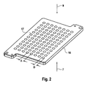
- a so far known device 1 according to FIG. 1 uses both the radiation flux of the light source 5 only very inefficiently for fluorescence excitation of the detection sites 2, as essentially the area around the detection sites 2, for example, the massive part of the heated lid of a microtiter plate is illuminated. Only the light which falls on the detection sites 2, for example through the holes provided for this in the heated lid of a microtiter plate, is actually available for fluorescence excitation. This is based on FIG. 2 illustrated.
- FIG. 2 shows such a heated lid 16, which is located at the top of the wells of a microtiter plate. It is usually opaque and has for each well a hole 17 through which the solution in the well is illuminated with excitation light 9 and through which the fluorescence signals 7 emitted from the solution are detected.
- the hole spacing d in the heated lid 16 is 9 mm, for example, according to the SBS standard microtiter format.
- the hole diameter D is 5.2 mm a little smaller than the diameter of the cylindrical part of the wells of 5.5 mm and significantly smaller than the hole spacing d. From hole pitch d and hole diameter D, the light loss by shading by the impermeable portions of the heated lid 16 can be calculated as follows.
- Each hole 17 in the heated lid 16 can be assigned a square whose edge length is just the hole spacing d and adjacent adjacent squares border each other without interspacing.
- ⁇ A is therefore given by purely geometric size relationships and can be interpreted as a "fill factor". This fill factor and thus the efficiency of the fluorescence excitation of the detection sites 2 are improved by the array optics arrangement according to the invention.
- the efficiency of fluorescence detection is also improved by the invention, since an optical device 1 according to the prior art also uses the radiation flux of the fluorescence signals 7 to the optical sensor 6 only inefficiently. Namely, the fluorescent light emitted from the dye molecules at the detection site 2 is emitted spatially isotropically. Only a small part of this light is detected by the detection optics and directed to the detector 6.
- the solid solid angle ⁇ tot which is illuminated by the fluorescence radiation, is 4 ⁇ .
- the invention improves both the efficiency of fluorescence excitation and the efficiency of fluorescence detection. This is achieved by setting an array optical arrangement 18 between the field lens 8 and the heated lid 16 or the arrangement of a multiplicity of detection locations 2.
- the components and location of the array optics assembly 18 are shown in FIG FIG. 3 illustrated.
- the array optics assembly 18 includes a field lens array 19 with field lens array elements 20 and a pupil lens array 21 with pupil lens array elements 22 and is disposed in the beam path between the field lens 8 and the array of a plurality of individual detection sites 2.
- the array optics assembly 18 could thus also be referred to as an array objective.
- the field lens array 19 is the field lens 8 and the pupil lens array 21 faces the plurality of detection sites 2.
- the field lens array 19 is arranged parallel to the pupil lens array 21.
- the optical device 1 thus has a number of optical channels corresponding to the number of wells of the microtiter plate, each optical channel comprising an associated field lens array element 20 and an associated pupil lens array element 22.
- the object plane is preferably the underside of the heated lid 16 facing the wells, as in the case of the optical device 1.
- This object plane forms a field plane, the field plane conjugated thereto lying in the field lens array element 20, namely on the surface of the field lens array.
- Array element 20, which is the pupil lens array element 22 is turned away.
- the field planes of the field lens 8 or of the field lens array element 20 and of the heated lid 16 also remain conjugate to one another with the array optical arrangement 18 according to the invention. More specifically, not the field lens 8 alone has a field plane, but the detection optics (imaging lens assembly 11) together with the field lens 8. Namely, both together form the top of the field lens array 19 on the optical sensor 6, not the field lens 8 alone. The same applies to the lighting branch.
- FIG. 4 shows an inventive array optics array 18 consisting of field lens array 19 and pupil lens array 21, wherein in a preferred embodiment, between the field lens array 19 and pupil lens array 21, a diaphragm array 23 is arranged.
- each well of the microtiter plate or each hole 17 in the heated lid 16 is a two-lens, comprising a field lens array element 20 and a pupil lens array element 22 assigned.
- the lenses are equal to each other.
- a pair of lenses formed from a field lens array element 20 and a pupil lens array element 22 is assigned to one of the detection sites 2.
- the microtiter plate and the heated lid 16 are removed from their original position relative to the field lens 8 (displaced by about 60 mm) and in the image plane (relative to the illumination with the excitation light 9) compared with the prior art because of the array optical assembly 18 placed therebetween.
- the 96 lenses of the array optics assembly 18 are placed.
- the object plane (based on the detection of the fluorescence signals 7) of the 96 objectives of the array optics assembly 18 the original position of the underside of the heated lid 16 is preferably selected as in the prior art.
- these lenses of the array optical arrangement 18 improve the filling factor of the illumination, on the other hand they increase the numerical aperture of the detection. This will be explained below on the basis of FIGS. 5 to 8 explained.
- FIGS. 5 and 6 each show a single channel of the 96-channel array optics assembly 18 consisting of a field lens array element 20, a pupil lens array element 22, and an aperture of the aperture array 23 located between both lenses in the vicinity of the pupil lens array element 22.
- FIG. 5 is the beam path for the fluorescence excitation with the excitation light 9 located in FIG. 6 the beam path for the fluorescence detection of the fluorescence signals 7 is shown.
- a pupil lens array element 22 of the pupil lens array 21 forms a field lens array element 20 of the field lens array 19 (or the edge of a field lens array element 20) on one of the detection sites 2 (ie on the lower edge of a hole 17 in the heated lid 16) are in the figures at the bottom and there form a field level.
- the respective associated hole 17 in the heated lid 16, which in the FIGS. 5 and 6 is not shown extends from the field plane at the detection sites 2 upwards toward the pupil lens array element 22nd
- field lens 8 Above the field lens array elements 20, i. on the entrance side of the field lens array elements 20 with respect to the excitation light 9 and on the exit side of the field lens array elements 20 relative to the fluorescence signals 7 is not shown field lens 8. There, so above the field lens array elements 20, the main rays parallel and the axes of the tufts are parallel, ie the arrangement is telecentric in this area.
- the field lens array elements 20 of the field lens array 19 generate illumination pupils for the excitation light 9 and detection pupils for the fluorescence signals 7.
- the array optical arrangement 18 images both fields (objects, images) and diaphragms (pupils). When designing a composite optical system, one should consider both the mapping of the fields and the image of the pupils.
- the axes of the tufts of rays for fluorescence detection are parallel to each other and also parallel to the optical axis.
- the bundles of rays for fluorescence excitation are on the input side (top in FIG. 5 ) also parallel to each other, but in the Contrary to the fluorescence detection slightly tilted with respect to the optical axis.
- the tilting is chosen such that the bundles of rays for fluorescence excitation and fluorescence detection at the field level (object level, at the detection locations 2) do not penetrate (see also FIG FIG. 10 ) to achieve separation between excitation light 9 and fluorescence signals 7.
- the input-side beam directions for the fluorescence excitation and the fluorescence detection are predetermined by the optics of the device 1. They are formed by the laterally separated apertures of the illumination beam path and the detection beam path in the optical device 1. As a rule, it is more advantageous to select the main beams of the detection parallel to the optical axis. A symmetry break usually leads to a deterioration of the imaging performance. Good imaging performance is more needed in practice for detection than for illumination.
- FIG. 7 shows in a combination of FIGS. 5 and 6 a section through a channel of an inventive array optical arrangement 18 with a diaphragm of the aperture array 23 with two separate apertures 24, 25, one for fluorescence excitation with the excitation light 9 and one for the fluorescence detection of the fluorescence signals 7.
- the beam paths for fluorescence excitation and for Fluorescence detection are shown together.
- the aperture 23 between field lens array element 20 and pupil lens array element 22 in this embodiment has two separate apertures 24, 25 per channel. But you can also provide only one aperture per channel, see above.
- the off-axis aperture 24 (left) allows the excitation light 9 to pass light for fluorescence excitation.
- the axial aperture 25 (right) passes the fluorescence signals 7 for fluorescence detection.
- the Aperture 24 allows detection light to pass as the fluorescence source radiates isotropically. However, this light is absorbed at the latest at the aperture of the detection optics.
- the detection locations 2, ie the holes 17 in the heated lid 16, are imaged by the pupil-lens array elements 22 in a format-filling manner (ie dimensionally and largely faithfully) on the upper side of the field-lens array elements 20. Thus, these tops and the holes 17 in the heated lid are optically conjugate.
- the plurality of detection sites 2 have a diameter D and are arranged at a distance d from each other, wherein the magnification ⁇ of the pupil lens array elements 22 is equal to the ratio of distance d to diameter D.
- each individual bi-lens of the array optics assembly 18 produces an image of the associated hole 17 of the heated lid 16 of size D of that image. From the point of view of the illumination optics, the holes 17 in the heated lid 16 then appear enlarged by the magnification ⁇ and the interspaces between the images of the holes 17 are shrunk to such an extent that they just touch tangentially.
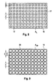
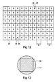
- FIG. 8 shows a plan view of the heated lid 16 of FIG. 2 as an object for imaging by the array optics array 18, the FIG. 9 the picture of the heated lid 17 of FIG. 2
- the array optics of the array optics assembly 18 thus produces only an enlarged image of the holes 17 without changing the distance d between them.
- the gain factor g D of the array optics array 18 for fluorescence detection is given by the following consideration.
- the numerical aperture NA in the object plane of the detection optics of the optical device 1 is 0.014. This plane is imaged in 96 separate channels from the array optics assembly 18 onto the underside of the heated lid 16. In this direction, the array optical arrangement 18 reduces in size.
- the array optics assembly 18 increases the fill factor (packing density) with respect to illumination of the wells with the excitation light 9, in the present example by a factor of 3. Further, the array optics assembly 18 increases the numerical aperture with respect to the detection of the fluorescence signals 7, in the present example by the factor ⁇ 3. However, the gain is approximately proportional to the square of the numerical aperture. The result then is the profit by a factor of 3 in the detection. Both together result in a signal gain of the fluorescence measurement with the optical device 1, in the present example by a factor of 9.
- Vignetting freedom means that all the rays of the illumination and detection optics of the optical device 1, the array optical assembly 18 must pass without shading of useful light in the beam path. Of course, this does not apply to other light (stray light, stray light), which is shaded by the heated lid 16 or the aperture array 23.
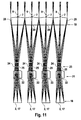
- the FIG. 10 shows the beam directions of the illumination and detection optics of the optical device 1 in the sine grid.
- the sine grid allows a direct interpretation of the beam directions as a numerical aperture. Shown are the beam directions at the location of the field lens array 19. At the location of the heated lid 16 (or the detection location 2) these beam directions look different again. In particular, these are then field-dependent (or else location-dependent). Since the illumination and detection optics of the optical device 1 is telecentric, the in FIG. 10 shown steel directions in the context of aberrations field independent. For one channel of the array optical arrangement 18, all beam directions of the detection system for the fluorescence signals 7 lie within the axial curve 27 (FIG. FIG.
- the curves 27, 28 themselves are given by the diaphragm edge.
- the dashed curve represents the optical axis-centered envelope 29 for all rays of all channels of the entire array optical array 18.
- the associated numerical aperture of the envelope 29 is 0.059.
- the array optics array 18 operates vignetting-free when its input numerical aperture is greater than the numerical aperture of the envelope 29 (here 0.059) and at the same time the input pupil position is telecentric.
- the input-side telecentricity of the array optics assembly 18 is achieved by placing a stop (apertures 24, 25 and aperture array 23) in the rear focal plane of the front lens (field lens array element 20) of the array optics assembly 18.
- the maximum beam height h in the diaphragm plane should be less than half the hole spacing d / 2, in order to avoid a spatial penetration of adjacent channels of the array optical assembly 18: H ⁇ / 2 d
- the focal length of the field lens array elements 20 when the focal length of the field lens array elements 20 is so small that the aperture images of the first and second apertures 24, 25 for a detection site 2 do not overlap, it may be desirable to separate excitation light 9 and fluorescence signals 7 to enable. Further, in some embodiments, it may be useful if the focal length of the field lens array elements 20 is so small that the aperture images of adjacent channels (adjacent detection locations 2) do not overlap to allow for suppression of stray light. Due to the periodicity of the array optics assembly 18, right edge tufts and left edge tufts can coincide on the input side.
- the front lenses separate the directly adjacent right edge tufts and left edge tufts and direct the beams spatially separated in the direction of the respective aperture. Since these front lenses (field lens array elements 20) are located directly in the field plane of the illumination and detection optics of the optical device 1, these are generally referred to as field lenses and here as field lens array elements 20.
- near-field lenses ie close to the field, that is, close to the object or image
- pupil-near lenses as pupil lenses.
- a field level is a plane that is illuminated or imaged, that is, an object, an image or an intermediate image.
- Pupils are apertures or images of apertures.
- Field lenses form pupils and pupil lenses form fields.
- the field lens array 19 is close to the field, the pupil lens array 21 and the diaphragm array 23 are close to the pupil.
- the field lens array elements 20 due to their close-to-field position and their comparatively large focal length, do not make a significant contribution to the total refractive power of the array optics assembly 18, ie they do not change the image position and image size negligibly. Their central function is rather in the local separation of the optical channels, ie they form pupils for the beam path, adjusted by the pupil position and the angles of the beams are limited.
- the field lens array elements 20 preferably provide for an exit side (at the viewing site, on the side of the detection sites 2) telecentric optics (in FIG. 11 above telecentric, below non-telecentric, as explained above), ie the image of the aperture lies in the infinite.
- a pupil is an image of an aperture stop. In an optical system, there are entrance pupils and exit pupils.
- Each field lens array element 20 generates in its focal plane an off-axis image of the aperture of the illumination system and an axial image of the aperture of the detection system. These pictures are separated by channel.
- pupil lens array element 22 Virtually the total refractive power of a lens pair of the array optics assembly 18 is concentrated in the respective rear lens (pupil lens array element 22). Since these are localized in the vicinity of the pupil, they are generally referred to as pupil lenses or here as pupil lens array element 22.
- the pupil lens array elements 22 form the edges of the field lens array elements 20 faithfully on the lower edges of the holes 17 of the heated lid 16 off.
- the holes 17 in the heated lid 16 thus act as an array of field diaphragms.
- a respective aperture array element (aperture, aperture) is placed, wherein the aperture array elements mask the images of the aperture of the illumination system and the images of the aperture of the detection system.
- the entirety of these aperture array elements form a diaphragm array 23.
- "Masking" in this sense means that the diaphragm array 23 forms a mask, each diaphragm array element comprising one or more mask elements a plurality of apertures, each associated with a field lens array element 20 and a pupil lens array element 23 and forms a mask for the beam path through the respective field lens array element 20 and pupil lens array element 23 (ie, for each "channel" of the array optics assembly 18).
- This masking is in the embodiment of FIGS. 2 to 12
- the shape of the aperture array elements may also be in the form of the field lens array elements 20 and / or the pupil lenses -Arraymaschine 23 and / or the detection sites 2 (holes 17 in the heated lid 16) correspond.
- the masking also in addition, be true to size.
- the size of the aperture array elements corresponds to the size of the illumination pupils of the excitation light 9 and / or the detection pupils of the fluorescence signals 7 and / or the pupils of the detection sites 2 (holes 17 in the heated lid 16).
- the masking does not necessarily have to be true to form and / or true to size.
- the apertures may not be circular.
- the two diaphragm images image of the aperture of the illumination system (illumination pupil of the excitation light 9) and image of the aperture of the detection system (detection pupil of the fluorescence signals 7) per channel can also be masked by a common, circumscribed rectangle Manufacturing accuracy and degrades the channel crosstalk only insignificantly.
- the array optics assembly 18 therefore has a diaphragm array 23 which forms a mask for the illumination pupils of the excitation light 9 and the detection pupils of the fluorescence signals 7.
- the aperture array 23 is arranged between the field lens array 19 and the pupil lens array 21.
- the aperture array 23 could also be between the pupil lens array 21 and the arrangement of a plurality of detection locations 2 (heated lid 16), in this case preferably close to the pupil lens array 21.
- FIG. 12 shows by way of example a plan view of such a diaphragm array 23 in which each diaphragm array element is formed from a pair of diaphragm openings 24, 25.
- the illustrated aperture array 23 is thus provided with 96 pairs of apertures 24, 25, which are each assigned to one of the 96 detection sites 2.
- the aperture pairs are arranged such that in each case a first aperture 24 of an aperture opening pair passes the excitation light 9 for a detection site 2 and a second aperture 25 of the aperture opening pair passes the fluorescence signals 7 from the detection site 2.
- the course of the imaginary lines which delimit the squares explained above with an edge length corresponding to the hole spacing d and the area AQ, is likewise shown for the purpose of illustration. In the case of real aperture arrays 23, these lines are generally absent.
- the essential task of the diaphragm array 23 is the suppression of crosstalk between the various channels of the array optical arrangement 18.
- the crosstalk may arise from internal reflections (directed stray light) or non-directional, diffused stray light in the array optics assembly 18, in particular in the pupil lens array 21.
- the total area of the holes 24, 25 in the aperture array 23 is obviously much smaller than the total area of the aperture array 23. This results in a very effective separation of useful and interfering light, already very close to the source of the fluorescence signals 7, the detection sites 2, and thus early in the detection beam path, which is very advantageous for the optical detection.
- the ratio of these areas can again be interpreted as a fill factor.
- the effectiveness of the diaphragm array 23 with respect to the suppression of crosstalk increases with decreasing filling factor.
- the array optics assembly 18 consists of a field lens array 19 and a pupil lens array 21 and preferably from an additional aperture array 23.
- the field lens array 19 generates illumination pupils and detection pupils, each corresponding to the number of detection sites 2 (FIG. 96 in each example).
- the aperture array 23 masks these pupils (in the example 192) to avoid local crosstalk.
- the pupil lens array 21 images the field lens array 19 onto the detection sites 2 (the multiwell plate).
- the array optics assembly 18 increases the fill factor (packing density) of the detection sites 2 (wells).
- the array optics array 18 increases the numerical aperture. From the geometry results nominally a signal gain (here by the factor 9).
- the field lens array elements 20 of the field lens array 19 need not necessarily be performed with a round boundary.
- the field lens array elements 20 are square.
- the FIG. 13 shows an image of a square field lens array element 20 in a circular hole 17 of the heated lid 16. With square boundary with an edge length corresponding to the hole spacing d in Walkerdeckel 16 (here 9 mm) can all field lens array elements 20 gapless, ie without the optical image add unused spaces between the field lens array elements 20 to each other. If you choose now as in FIG.
- the gain factor g DQ with the array optics array 18 for fluorescence detection is no longer given by the sheer ratio of ⁇ ' DQ to ⁇ D , unlike the case of the round field lens array elements. Rather, it has to be considered that not the entire circular area of the hole 17 but only the inscribed square is imaged on the optical sensor 6.
- This value is significantly greater than the overall gain factor g tot for round field lens array elements 20 of 9.0 (see above).
- the bottom circular edges of the holes 17 of the heated lid 16 act as an array of field stops when the array optics assembly 18 is laid out to be faithfully imaged onto the edges of circularly shaped field lens array elements 20.
- the mapping of the corners of the field lens array elements 20 to the edge of the hole 17 in the heated lid 16 sets in terms of the gain factor
- FIG. 14 shows such an array optics array 18 with square-edged field lens array elements 20 in a view from "above”, ie from the side of the excitation light 9, and
- FIG. 15 shows the array optics assembly 18 of FIG FIG. 14 in a view from "bottom”, ie from the side of the fluorescence signals 7.
- the aperture array elements are here formed so that they have a rectangular shape and per channel of the field lens array 22, ie per field lenses Array element 20 and associated pupil lens array element 22, in each case only one aperture is present, ie an aperture in common for the excitation light 9 and the fluorescence signals 7 of the channel.
Abstract
Description
Die vorliegende Erfindung betrifft das Gebiet der DNA-Analyse. Insbesondere betrifft die vorliegende Erfindung eine Vorrichtung zum parallelen Abbilden von Fluoreszenzintensitäten von einer Vielzahl von Detektionsorten, und hierbei insbesondere die Anregungs- und Abbildungsoptik für die Fluoreszenzdetektion von Fluoreszenz-Signalen.The present invention relates to the field of DNA analysis. In particular, the present invention relates to a device for parallel imaging of fluorescence intensities from a plurality of detection sites, and in particular the excitation and imaging optics for the fluorescence detection of fluorescence signals.
Dem Fachmann sind verschiedene Anwendungsfälle von Fluoreszenzmethoden und Fluoreszenztechniken zum Analysieren biologischer Proben bekannt. Im Falle elektrophoretischer Methoden werden Proteine oder DNA mit einer Fluoreszenzsonde markiert, um ihre elektrophoretischen Banden in Gelen oder Säulen sichtbar zu machen. Außerdem basieren die meisten bisherigen Anwendungsfälle von Biochips auf einer Fluoreszenzauslesung, wobei das spezifische Binden eines fluoreszenzmarkierten Zielmoleküls an ein Sondenmolekül, das auf einem festen Träger immobilisiert ist, überwacht wird. Anwendungen der DNA-Analyse in der flüssigen Phase umfassen Fluoreszenzhybridisierungssonden wie den Farbstoff SybrGreenl, der an doppelsträngige DNA bindet, oder FRET-Sonden (Fluoreszenz-Resonanz-Energietransfer), die zwei Fluoreszenzsonden und Energietransfer nutzen. Ein sehr wichtiger Anwendungsfall für Fluoreszenzmethoden in der flüssigen Phase ist die Mengenbestimmung von PCR-Produkten in Echtzeit, die sogenannte Echtzeit-PCR.The person skilled in various applications of fluorescence methods and fluorescence techniques for analyzing biological samples are known. In the case of electrophoretic methods, proteins or DNA are labeled with a fluorescent probe to visualize their electrophoretic bands in gels or columns. In addition, most previous applications of biochips are based on fluorescence reading, where the specific binding of a fluorescently labeled target molecule to a probe molecule immobilized on a solid support is monitored. Applications of liquid phase DNA analysis include fluorescent hybridization probes such as SybrGreenl dye which binds to double-stranded DNA or FRET probes (fluorescence resonance energy transfer) utilizing two fluorescent probes and energy transfer. A very important application for fluorescence methods in the liquid phase is the real-time PCR quantification of PCR products.
Die PCR (Polymerase Chain Reaction) ist ein Verfahren zum Amplifizieren oder Multiplizieren von Mengen doppelsträngiger DNA (Desoxyribonucleinsäure). In einer PCR-Apparatur hat ein Block zum thermischen Zyklieren eine oder mehrere Haltevorrichtungen mit Probengefäßchen (Wells), die eine Mischung aus Bestandteilen für eine Reaktion enthalten, mit der ausgehend von einer Startmenge der DNA mehr DNA gewonnen wird. Die Startbestandteile umfassen in einer wässrigen Lösung eine "Impfmenge" der DNA, bestimmte primäre DNA, DNA Elemente, Enzyme und andere Chemikalien. Die Temperatur des Blocks wird zwischen einer niedrigen Extensionsphase der PCR-Reaktion von ca. 60 °C, bei der alle DNA-Stränge in Doppelstränge rekombiniert sind, und einer höheren Denaturierungsphase von ca. 95 °C, in der die DNA denaturiert oder in Einzelstränge gespalten ist, zykliert. Ein solches Temperaturprogramm verdoppelt im Wesentlichen die DNA in jedem Zyklus, wodurch die Möglichkeit zum Replifizieren wesentlicher Mengen der DNA von einer kleinen Ausgangsmenge besteht. Die quantitative Bestimmung der DNA erfolgt mit Fluoreszenzmessungen, auch in Echtzeit.PCR (Polymerase Chain Reaction) is a method of amplifying or multiplying amounts of double-stranded DNA (deoxyribonucleic acid). In a PCR apparatus, a thermal cycling block has one or more holding jars (wells) containing a mixture of ingredients for a reaction that yields more DNA from a starting amount of the DNA. The starting ingredients in an aqueous solution comprise a "seed" of the DNA, certain primary DNA, DNA elements, enzymes, and other chemicals. The temperature of the block is between a low extension phase of the PCR reaction of about 60 ° C, in which all DNA strands are recombined in double strands, and a higher denaturation phase of about 95 ° C, in which the DNA is denatured or in single strands split, cycled. Such a temperature program essentially doubles the DNA in each cycle, allowing for the ability to replicate substantial amounts of the DNA from a small starting amount. The quantitative determination of the DNA takes place with fluorescence measurements, also in real time.
In all diesen Fällen wird eine ein optisches Gerät, d.h. eine Anregungs- und Lesevorrichtung für Fluoreszenz benötigt, die Licht einer bestimmten Wellenlänge bereitstellt, um den Fluoreszenzmarker des Assays anzuregen, und die in der Lage ist, das Fluoreszenzlicht von dem Marker, das mit einer etwas unterschiedlichen Wellenlänge ausgestrahlt wird, zu erfassen. Ein großes Problem aller derartigen Fluoreszenz-Messgeräte ist die enorme Intensität des Anregungslichts im Vergleich zu dem Fluoreszenzlicht, das vom Farbstoff ausgestrahlt wird, und daher muss man sicherstellen, dass der Anregungsstrahl den Detektor nicht trifft, um die Fluoreszenz-Signale exakt überwachen zu können. Mit anderen Worten: Der Strahlengang (Lichtweg) des Anregungslichtes muss sich von dem Strahlengang (Lichtweg) des Fluoreszenzlichtes mindestens teilweise unterscheiden. Hierzu sind folgende Maßnahmen üblich: a) Eine spektrale Trennung durch Anregungs- und Emissionsfilter, deren Spektren sich nicht signifikant überlappen. b) Die Verwendung einer Auflicht- (oder auch Epi-) Beleuchtung bzw. einer seitlichen Beleuchtung. Dabei zeigt kein Strahl des Beleuchtungslichtes in eine Richtung, die direkt detektiert werden kann (Dunkelfeld). Man benötigt zumindest einen Reflex, elastische Streuung oder eben die Fluoreszenz (inelastische Streuung). Die Maßnahme b) wird in der Regel als Unterstützung für die Maßnahme a) angewendet, da die Filterblockung gemäß Maßnahme a) nicht perfekt ist.In all these cases, an optical device, ie, a fluorescence excitation and reading device, is needed that provides light of a particular wavelength to excite the fluorescent label of the assay and that is capable of detecting the fluorescent light from the marker that is incident on a marker something different wavelength is emitted to capture. A major problem with all such fluorescence gauges is the enormous intensity of the excitation light as compared to the fluorescent light emitted by the dye, and therefore one must ensure that the excitation beam does not strike the detector to accurately monitor the fluorescence signals. In other words, the beam path (light path) of the excitation light must be at least partially different from the beam path (light path) of the fluorescent light. The following measures are customary for this: a) A spectral separation by excitation and emission filters whose spectra do not significantly overlap. b) The use of reflected light (or epi) lighting or side lighting. In this case, no beam of the illumination light in a direction that can be detected directly (dark field). At least one reflex, elastic scattering or just the fluorescence (inelastic scattering) is needed. The measure b) is usually used as support for measure a) as the filter blockage is not perfect according to measure a).
Die Realisierung des Fluoreszenzprinzips ist ziemlich einfach, wenn nur eine Fluoreszenzsonde in der flüssigen Phase von z.B. einer Kapillare überwacht werden muss. Hier reicht z.B. eine Weißlichtquelle zusammen mit einem Satz dichroitischer Spiegel und Filter aus, um die Anforderungen zu erfüllen. Wenn jedoch mehr als ein Fluoreszenzmarker in der Probe vorhanden ist, muss eine laterale Verteilung der Stellen auf einem festen Träger oder die Fluoreszenz einer Mikrotiterplatte überwacht werden (ausgenommen wenn verschiedene Farbstoffe in einem einzigen Probengefäß vorhanden sind und detektiert werden), und die Anforderungen an das optische Gerät für die Fluoreszenz-Messung sind schwieriger zu erfüllen.The realization of the principle of fluorescence is quite simple if only one fluorescent probe in the liquid phase of e.g. a capillary must be monitored. Here, for example, a white light source along with a set of dichroic mirrors and filters to meet the requirements. However, if more than one fluorescent label is present in the sample, a lateral distribution of the sites on a solid support or the fluorescence of a microtiter plate must be monitored (except when different dyes are present and detected in a single sample vessel), and the requirements of Optical devices for fluorescence measurement are more difficult to meet.
Grundsätzlich gibt es zwei verschiedene Strategien, die Fluoreszenz einer lateralen Verteilung von Detektionsorten anzuregen und zu überwachen. Die erste Strategie ist, die laterale Verteilung von Detektionsorten abzutasten, wobei nacheinander die einzelnen Detektionsorte jeder für sich analysiert werden. Die zweite Strategie ist, die gesamte Verteilung von Detektionsorten gleichzeitig zu beleuchten und die entsprechende Fluoreszenz auf eine Mehrzahl optischer Sensoren, z.B. einen CCD-Chip abzubilden. Die Abtaststrategie hat den offensichtlichen Nachteil, dass entweder der Träger in zwei Dimensionen bewegt werden muss (siehe z.B.
Eine Alternative zu der gleichmäßigen Beleuchtung über die gesamte Verteilung von Detektionsorten ist die Benutzung einer Anordnung von Lichtquellen, wobei jeder Detektionsort durch seine eigene Lichtquelle beleuchtet wird. Die
Bezüglich der Anforderung, den Strahlengang des Anregungsstrahls und des Fluoreszenzlichts (der detektierten Fluoreszenz-Signale) mindestens teilweise zu trennen, gibt es wiederum zwei verschiedene Möglichkeiten. Die erste Möglichkeit ist die sogenannte Epi-Illumination, wobei Strahlteiler eingesetzt werden und der Anregungsstrahl und das Fluoreszenzlicht sich mindestens einen Teil des optischen Systems teilen. Die zweite Möglichkeit ist die Benutzung von schräger Beleuchtung. Hier ist der Anregungsstrahl auf eine solche Weise angeordnet, dass er einen bestimmten Winkel zur Normalen der Trägerfläche aufweist und die entsprechende Reflexion des Anregungsstrahls außerhalb des Öffnungswinkels des Erfassungssystems liegt (z.B.
Die
Die
Die
Die
Die
Wenngleich mit diesen Vorrichtungen gute Ergebnisse erzielt werden konnten, hat es sich in der Praxis erwiesen, dass die Lichtausbeute noch verbessert werden kann, um noch kleinere Fluoreszenz-Signale detektieren zu können oder Fluoreszenz-Signale mit einem besseren Signal-Rausch-Verhältnis oder in besserer Auflösung detektieren zu können.Although good results could be obtained with these devices, it has been found in practice that the luminous efficiency can be improved to detect even smaller fluorescence signals or fluorescence signals with a better signal-to-noise ratio or better Detect resolution.
Die Aufgabe der vorliegenden Erfindung besteht darin, eine verbesserte Vorrichtung bzw. ein verbessertes optisches Gerät zum gleichzeitigen Überwachen von Fluoreszenz-Signalen von einer lateralen Verteilung einer Vielzahl einzelner Detektionsorte bereitzustellen, indem der Strahlengang in Bezug auf eine höhere Lichtausbeute optimiert wird. In einem Aspekt der vorliegenden Erfindung bezieht sich das zu lösende Problem auf Verbesserungen in der Überwachung von Echtzeit-Multiplex-PCR in einem Mikrotiterplattenformat.The object of the present invention is to provide an improved apparatus for simultaneously monitoring fluorescence signals from a lateral distribution of a plurality of individual detection sites by optimizing the beam path with respect to a higher light output. In one aspect of the present invention, the problem to be solved relates to improvements in the monitoring of real-time multiplex PCR in a microtiter plate format.
Folglich richtet sich die Erfindung auf ein optisches Gerät zum Abbilden von Fluoreszenz-Signalen von einer Anordnung einer Vielzahl einzelner Detektionsorte mit einer gleichmäßige Anregung über den gesamten Bereich der Anordnung, exaktem Abbilden der entsprechenden Fluoreszenz-Signale und einer hoher Lichtausbeute.Thus, the invention is directed to an optical device for imaging fluorescence signals from an array of a plurality of discrete detection sites with uniform excitation over the entire region of the array, accurate imaging of the corresponding fluorescence signals, and high luminous efficacy.
Genauer gesagt richtet sich die Erfindung auch auf ein optisches Gerät zum gleichzeitigen Analysieren einer Vielzahl von PCR-Amplifikationen in Echtzeit, die in den Wells einer Mikrotiterplatte stattfinden, oder zum Abbilden der Fluoreszenz-Intensität eines Mikroarrays als Maß für spezifische Wechselwirkungen zwischen Ziel und Sonde.More specifically, the invention is also directed to an optical device for simultaneously analyzing a plurality of PCR amplifications in real time that take place in the wells of a microtiter plate or for imaging the fluorescence intensity of a microarray as a measure of specific target-probe interactions.
Diese Aufgabe wird erfindungsgemäß durch ein optisches Gerät mit den Merkmalen des Patentanspruchs 1 gelöst. Bevorzugte Ausgestaltungen ergeben sich aus den abhängigen und den nebengeordneten Patentansprüchen und der nachfolgenden Beschreibung mit zugehörigen Zeichnungen.This object is achieved by an optical device with the features of
Ein erfindungsgemäßes optisches Gerät zum Abbilden von Fluoreszenz-Signalen von einer Anordnung einer Vielzahl einzelner Detektionsorte umfasst also
- eine Haltevorrichtung zum Halten eines ebenen Trägers mit einer Anordnung einer Vielzahl einzelner Detektionsorte;
- mindestens eine Lichtquelle zum Ausstrahlen von Licht mit mindestens einer Anregungsfrequenz;
- einen optischen Sensor, der so angeordnet ist, dass er Fluoreszenz-Signale von der Anordnung einer Vielzahl einzelner Detektionsorte empfängt, und der so ausgebildet ist, dass er computerlesbare Primärdaten erzeugt;
- eine Feldlinse, die so angeordnet ist, dass sie Anregungslicht von der Lichtquelle zu der Anordnung einer Vielzahl einzelner Detektionsorte und Fluoreszenz-Signale von der Anordnung einer Vielzahl einzelner Detektionsorte zum optischen Sensor überträgt;
- eine Anregungslinsenanordnung, die so angeordnet ist, dass sie Anregungslicht von der Lichtquelle zur Feldlinse überträgt; und
- eine Abbildungslinsenanordnung, die so angeordnet ist, dass sie Fluoreszenz-Signale von der Feldlinse zum optischen Sensor überträgt;
- sie eine Arrayoptikanordnung umfasst,
- die ein Feldlinsenarray mit Feldlinsen-Arrayelementen und ein Pupillenlinsenarray mit Pupillenlinsen-Arrayelementen umfasst,
- wobei die Arrayoptikanordnung im Strahlengang zwischen der Feldlinse und der Anordnung einer Vielzahl einzelner Detektionsorte angeordnet ist.
- a holding device for holding a planar carrier having an array of a plurality of individual detection locations;
- at least one light source for emitting light having at least one excitation frequency;
- an optical sensor arranged to receive fluorescence signals from the array of a plurality of discrete detection sites and configured to generate computer readable primary data;
- a field lens arranged to transmit excitation light from the light source to the array of a plurality of discrete detection sites and fluorescence signals from the array of a plurality of discrete detection sites to the optical sensor;
- an excitation lens array arranged to transmit excitation light from the light source to the field lens; and
- an imaging lens array arranged to transmit fluorescence signals from the field lens to the optical sensor;
- it includes an array optics assembly,
- comprising a field lens array with field lens array elements and a pupil lens array with pupil lens array elements,
- wherein the array optics array is disposed in the optical path between the field lens and the array of a plurality of individual detection sites.
In einer bevorzugten Ausbildung sind der Strahlengang des Anregungslichts und der Strahlengang der Fluoreszenz-Signale von der Vielzahl einzelner Detektionsorte auf der Objektseite der Feldlinse telezentrisch, d.h. das optische Gerät verwendet eine telezentrische Pupillenlage. Genauer ausgedrückt ist im Rahmen der Erfindung der Strahlengang auf der Objektseite der Feldlinse und auf der Objektseite des Feldlinsenarrays telezentrisch. Auf der anderen Seite, d.h. zwischen dem Pupillenlinsenarray und der Anordnung einer Vielzahl einzelner Detektionsorte, ist der Strahlengang nicht mehr telezentrisch. Hier wird auch keine Telezentrie mehr benötigt. Jeder Detektionsort "sieht" durch die periodische Arrayoptikanordnung die gleiche, nicht-telezentrische Pupille für Beleuchtung und Detektion. Im Stand der Technik ist die Detektionsoptik telezentrisch auf der Seite der Feldlinse, aber nicht auf Seite des optischen Sensors, und die Beleuchtungsoptik ist telezentrisch auf der Seite der Feldlinse und auch auf der Seite eines ggf. verwendeten Lichtmischstabes.In a preferred embodiment, the beam path of the excitation light and the beam path of the fluorescence signals from the plurality of individual detection sites on the object side of the field lens are telecentric, i. the optical device uses a telecentric pupil layer. More specifically, within the scope of the invention, the beam path is telecentric on the object side of the field lens and on the object side of the field lens array. On the other hand, i. between the pupil lens array and the arrangement of a plurality of individual detection sites, the beam path is no longer telecentric. Here no telecentric is needed anymore. Each detection site "sees" the same non-telecentric pupil for illumination and detection through the periodic array optics assembly. In the prior art, the detection optics are telecentric on the side of the field lens, but not on the side of the optical sensor, and the illumination optics are telecentric on the side of the field lens and also on the side of a possibly used light mixing rod.
Die Erfindung ermöglicht nicht nur eine höhere Lichtausbeute, um noch kleinere Fluoreszenz-Signale oder Fluoreszenz-Signale mit einem verbesserten Signal-Rausch-Verhältnis oder in besserer Auflösung detektieren zu können, sondern zahlreiche weitere Vorteile, z.B. auch eine schnellere Durchführung der Fluoreszenz-Messung. Ferner werden nach dem Stand der Technik Hochleistungslampen mit hoher Leuchtdichte verwendet, z.B. Xenon-Bogenlampen, um die bislang geringe Lichtausbeute zu kompensieren. Derartige Hochleistungslampen haben jedoch nicht nur eine hohe thermische Verlustleistung, die eine aufwendige Wärmeabfuhr oder Kühlung erfordert, sondern auch eine relativ kurze Lebensdauer, die meist in der Größenordnung von ca. 500 Stunden liegt. Entsprechend häufig ist im Stand der Technik ein Lampenwechsel erforderlich. Wenn die Lampe gar während einer laufenden Messung, z.B. einer Echtzeit-PCR, ausfällt, kann sogar die gesamte Messung einer bestimmten Probe verloren gehen. Der Signalgewinn und die Empfindlichkeitsverbesserung durch die Erfindung vermeidet diese Probleme und schafft auch die Möglichkeit, schwächere und damit langlebigere Lampen und auch alternative Lichtquellen, z.B. LEDs mit einer höheren Lebensdauer und Zuverlässigkeit, zu verwenden.The invention not only allows a higher luminous efficacy to detect even smaller fluorescence signals or fluorescence signals with an improved signal-to-noise ratio or better resolution, but numerous other advantages, including a faster implementation of the fluorescence measurement. Furthermore, the prior art high-performance lamps are used with high luminance, such as xenon arc lamps to compensate for the low light output so far. However, such high-power lamps not only have a high thermal power loss, which requires a complex heat dissipation or cooling, but also a relatively short life, which is usually in the order of about 500 hours. Correspondingly, a change of lamp is necessary in the prior art. If the lamp fails even during a running measurement, eg a real-time PCR, even the entire measurement of a certain sample can be lost. The signal gain and sensitivity improvement of the invention avoids these problems and also provides the opportunity to use weaker and thus longer lasting lamps as well as alternative light sources, eg LEDs with a longer life and reliability.
Ein bedeutsamer Vorteil der Erfindung ist demnach die Verlängerung der Lebensdauer der verwendeten Lichtquelle.A significant advantage of the invention is therefore the extension of the life of the light source used.
Im Kontext dieser Erfindung fasst eine Anordnung einer Vielzahl einzelner Detektionsorte Objekte zusammen, die aus zwei oder mehr räumlich getrennten und lateral verteilten Detektionsorten bestehen. Bei den Detektionsorten kann es sich z.B. um Wells einer Mikrotiterplatte oder um funktionalisierte Flächenbereiche eines Objektträgers oder Glasträgers handeln. In der Mehrzahl der Fälle wird die Anordnung einer Vielzahl einzelner Detektionsorte gleichförmig, gleichmäßig, auf einheitliche Art und Weise oder in einem bestimmten Raster angeordnet sein und jeder Detektionsort wird einen anderen Inhalt aufweisen, um eine Multiplex-Analyse durchzuführen.In the context of this invention, an array of a plurality of discrete detection sites combines objects that consist of two or more spatially separated and laterally distributed detection sites. The detection sites may be e.g. to act wells of a microtiter plate or functionalized areas of a slide or glass slide. In the majority of cases, the array of a plurality of individual detection sites will be arranged uniformly, uniformly, uniformly, or in a particular grid, and each detection site will have a different content to perform a multiplex analysis.
Im Rahmen dieser Erfindung ist der ebene Träger der Anordnung bevorzugt eine ebene feste Phase. Im Falle eines Mikroarrays ist der ebene Träger der Anordnung die Fläche dieser ebenen festen Phase, wo die Detektionsorte angeordnet sind. Im Falle einer Mikrotiterplatte ist der ebene Träger der Anordnung die Ebene, wo die Öffnungen der Wells angeordnet sind. Der ebene Träger der Anordnung ist durch eine Haltevorrichtung fixiert, um jeden einzelnen Detektionsort an der Sollposition innerhalb des Strahlengangs zu fixieren.In the context of this invention, the planar support of the arrangement is preferably a flat solid phase. In the case of a microarray, the planar support of the array is the face of this planar solid phase where the detection sites are located. In the case of a microtiter plate, the planar support of the assembly is the plane where the openings of the wells are located. The planar support of the arrangement is fixed by a holding device in order to fix each individual detection location at the desired position within the beam path.
Im Rahmen dieser Erfindung umfasst der Ausdruck Lichtquelle Leuchtmittel, die Licht mit einer einzigen Frequenz oder mit einer Vielzahl verschiedener Frequenzen ausstrahlen. Außerdem kann die Lichtquelle eine Anordnung von mehr als nur einem Leuchtmittel sein.In the context of this invention, the term light source includes illuminants that emit light at a single frequency or at a plurality of different frequencies. In addition, the light source may be an array of more than one light source.
Im Kontext dieser Erfindung ist ein optischer Sensor (Detektor, Wandler) eine Vorrichtung zum Umwandeln von sichtbarem Licht in elektrische Signale, die von einem Computer verarbeitet werden können. Der optische Sensor kann einen einzelnen oder mehrere optische Sensoren umfassen. Eine bevorzugte Ausführungsform ist ein optischer Sensor mit mehreren optischen Sensoren, die in einer räumlich verteilten Anordnung platziert sind, die vorzugsweise entsprechend der Anordnung der Vielzahl einzelner Detektionsorte ausgebildet ist. Bevorzugte Ausführungsformen sind Halbleiterbauelemente, beispielsweise Photodioden, oder insbesondere ladungsgekoppelte Bauelemente, beispielsweise ein CCD-Chip.In the context of this invention, an optical sensor (detector, transducer) is a device for converting visible light into electrical signals that can be processed by a computer. The optical sensor may comprise a single or multiple optical sensors. A preferred embodiment is an optical sensor having a plurality of optical sensors placed in a spatially distributed arrangement, preferably according to the arrangement of the plurality of individual ones Detection locations is formed. Preferred embodiments are semiconductor components, for example photodiodes, or in particular charge-coupled components, for example a CCD chip.
Im Rahmen dieser Erfindung ist eine telezentrische Optik eine Optik mit einer Aperturblende, die durch die optischen Elemente zwischen der Aperturblende und dem Objekt in die Unendlichkeit projiziert wird. Mit anderen Worten sind die Hauptstrahlen einer telezentrischen Optik im Objektraum quasiparallel. Die Bezeichnung Hauptstrahlen wird für alle Strahlen benutzt, die durch das Zentrum der Aperturblende gehen. Die Bezeichnungen Objekt, Objektebene und Objektraum werden benutzt, um den ebenen Träger mit der Anordnung einer Vielzahl einzelner Detektionsorte zu beschreiben. In der telezentrischen Optik weisen die Anregungslinsenanordnung und die Abbildungslinsenanordnung beide ihre eigene Aperturblende auf. Die telezentrische Optik ist telezentrisch für den Strahlengang der Anregung und den Strahlengang der Erfassung der Fluoreszenz-Signale auf der Feldlinsenseite der Arrayoptikanordnung. Jeder Objektpunkt in einer Ebene senkrecht zur optischen Achse entspricht einem Hauptanregungsstrahl sowie einem Haupterfassungsstrahl. Da alle Hauptanregungsstrahlen und auch alle Haupterfassungsstrahlen quasiparallel sind, wird eine gute gleichmäßige laterale Verteilung in der Objektebene sichergestellt und die Detektionsorte in der Mitte der Anordnung sind vergleichbar mit denen am Rand der Anordnung.In the context of this invention, a telecentric optic is optics with an aperture stop projected into infinity by the optical elements between the aperture stop and the object. In other words, the principal rays of telecentric optics in the object space are quasi-parallel. The term principal rays is used for all rays passing through the center of the aperture stop. The terms object, object plane and object space are used to describe the planar carrier with the arrangement of a plurality of individual detection sites. In the telecentric optic, the excitation lens arrangement and the imaging lens arrangement both have their own aperture stop. The telecentric optic is telecentric for the excitation beam path and the optical path for detecting the fluorescence signals on the field lens side of the array optics assembly. Each object point in a plane perpendicular to the optical axis corresponds to a main excitation beam and a main detection beam. Since all the main excitation beams and also all the main detection beams are quasi-parallel, good uniform lateral distribution in the object plane is ensured and the detection locations in the center of the array are comparable to those at the edge of the array.
In der vorliegenden Erfindung weist eine telezentrische Optik immer eine Feldlinse auf. Im Kontext dieser Erfindung ist die Feldlinse eine Linse, die dem Objekt am nächsten ist (bezogen auf eine Ausführungsform des optischen Gerätes ohne die erfindungsgemäße Arrayoptikanordnung), von allen Anregungslichtstrahlen und allen Fluoreszenz-Signalen durchlaufen wird, eine oder mehrere Komponenten aufweisen kann und zusammen mit zusätzlichen optischen Komponenten der Vorrichtung zur Telezentrizität im Objekt- und/oder im Bildraum der Vorrichtung beiträgt. Die eine oder die mehreren Komponenten (Achromat) der Feldlinse können selbst Linsenelemente sein, die räumlich getrennt sind. Die Feldlinse bestimmt das Sehfeld des optischen Gerätes.In the present invention, a telecentric optic always has a field lens. In the context of this invention, the field lens is a lens closest to the object (relative to an embodiment of the optical device without the array optics assembly) of all the excitation light rays and all fluorescence signals, may have one or more components, and be co-located with contributes additional optical components of the device for telecentricity in the object and / or in the image space of the device. The one or more components (achromat) of the field lens may themselves be lens elements that are spatially separated. The field lens determines the field of view of the optical device.
Im Rahmen dieser Erfindung ist eine telezentrische Optik bevorzugt ferner eine Optik, die eine sehr kleine Apertur aufweist und somit eine hohe Tiefenschärfe bereitstellt. Mit anderen Worten: das telezentrische Licht einer solchen telezentrischen Optik ist für alle Punkte quer über das Objekt hinweg, die zu der optischen Achse im Objekt- und/oder Abbildungsraum parallel sind, quasiparallel zu den Hauptstrahlen. Daher ist die Qualität einer Anregungsoptik oder einer Abbildungsoptik, bei der Telezentrie im Objektraum benutzt wird, für den Abstand eines bestimmten Objektpunktes von der Optik unempfindlich. Die Apertur einer telezentrischen Optik wird ins Unendliche abgebildet. Die Benutzung von telezentrischem Licht stellt außerdem eine gute seitliche Homogenität quer über den Lichtstrahl hinweg sicher, und die Detektionsorte, die sich in der Mitte der Anordnung befinden, sind mit denjenigen vergleichbar, die sich an dem Rand der Anordnung befinden.In the context of this invention, a telecentric optic is furthermore preferably an optic which has a very small aperture and thus provides a high depth of focus. In other words, the telecentric light of such telecentric optics is quasi-parallel to the principal rays for all points across the object that are parallel to the optical axis in the object and / or imaging space. Therefore, the quality of excitation optics or imaging optics using telecentricity in object space is insensitive to the distance of a particular object point from the optics. The aperture of a telecentric optic is imaged into the infinite. The use of telecentric light also ensures good lateral homogeneity across the light beam, and the detection locations located in the center of the array are comparable to those located at the edge of the array.
Die Feldlinse der vorliegenden Erfindung überträgt Anregungslicht von der Lichtquelle zu der Anordnung einer Vielzahl einzelner Detektionsorte und überträgt Fluoreszenz-Signale von der Anordnung einer Vielzahl einzelner Detektionsorte zum optischen Sensor. Dies schließt nicht aus, dass zusätzliche optische Komponenten in den Strahlengang eingebracht werden, z.B. zwischen der Lichtquelle und der Feldlinse, zwischen der Feldlinse und dem optischen Sensor oder zwischen der Feldlinse und der Anordnung einer Vielzahl einzelner Detektionsorte (insbesondere eine erfindungsgemäße Arrayoptikanordnung).The field lens of the present invention transmits excitation light from the light source to the array of a plurality of discrete detection sites and transmits fluorescence signals from the array of a plurality of discrete detection sites to the optical sensor. This does not exclude that additional optical components are introduced into the beam path, e.g. between the light source and the field lens, between the field lens and the optical sensor or between the field lens and the arrangement of a plurality of individual detection sites (in particular an array optics arrangement according to the invention).
Der Einfallswinkel α ist definiert als der Winkel zwischen den quasiparallelen Hauptstrahlen des Anregungslichtstrahls und der Normalen der Grenzfläche, die im Rahmen dieser Erfindung der Träger der Anordnung ist.The angle of incidence α is defined as the angle between the quasi-parallel principal rays of the excitation light beam and the normal of the interface, which in the context of this invention is the carrier of the device.
Gemäß einem abgewandelten Aspekt der vorliegenden Erfindung richtet sie sich auf ein optisches Gerät zum Abbilden von Chemilumineszenz- oder Biolumineszenz-Signalen von einer Anordnung einer Vielzahl einzelner Detektionsorte, umfassend
- eine Haltevorrichtung zum Halten eines ebenen Trägers mit einer Anordnung einer Vielzahl einzelner Detektionsorte;
- einen optischen Sensor, der so angeordnet ist, dass er Chemilumineszenz- oder Biolumineszenz-Signale von der Anordnung einer Vielzahl einzelner Detektionsorte empfängt, und der so ausgebildet ist, dass er computerlesbare Primärdaten erzeugt;
- eine Feldlinse, die so angeordnet ist, dass sie Chemilumineszenz- oder Biolumineszenz-Signale von der Anordnung einer Vielzahl einzelner Detektionsorte zum optischen Sensor überträgt;
- eine Abbildungslinsenanordnung, die so angeordnet ist, dass sie Chemilumineszenz- oder Biolumineszenz-Signale von der Feldlinse zum optischen Sensor überträgt;
- es eine Arrayoptikanordnung umfasst,
- die ein Feldlinsenarray mit Feldlinsen-Arrayelementen und ein Pupillenlinsenarray mit Pupillenlinsen-Arrayelementen umfasst,
- wobei die Arrayoptikanordnung im Strahlengang zwischen der Feldlinse und der Anordnung einer Vielzahl einzelner Detektionsorte angeordnet ist.
- a holding device for holding a planar carrier having an array of a plurality of individual detection locations;
- an optical sensor arranged to receive chemiluminescent or bioluminescent signals from the array of a plurality of discrete detection sites, and configured to generate computer readable primary data;
- a field lens arranged to transmit chemiluminescent or bioluminescent signals from the array of a plurality of discrete detection sites to the optical sensor;
- an imaging lens assembly arranged to transmit chemiluminescent or bioluminescent signals from the field lens to the optical sensor;
- it includes an array optics assembly,
- comprising a field lens array with field lens array elements and a pupil lens array with pupil lens array elements,
- wherein the array optics array is disposed in the optical path between the field lens and the array of a plurality of individual detection sites.
Ein weiterer Aspekt dieser Erfindung ist ein Echtzeit-PCR-Gerät umfassend
- ein optisches Gerät gemäß der Erfindung und
- Mittel zum Heizen und Kühlen eines Trägers mit einem oder mehreren Wells, von denen jeder ein Reaktionsgemisch enthält, das zu einer PCR-Reaktion in der Lage ist.
- an optical device according to the invention and
- Means for heating and cooling a carrier with one or more wells, each containing a reaction mixture capable of PCR reaction.
Im Rahmen dieser Erfindung umfassen die Mittel zum Heizen und Kühlen beliebige Mittel, die in der Lage sind, die Temperatur der Anordnung einer Vielzahl einzelner Detektionsorte auf eine zyklische Art und Weise zu steuern und zu ändern, um eine zyklische PCR-Amplifikation von Nukleinsäuren durchzuführen. Jeder PCR-Zyklus umfasst mehrere verschiedene Schritte: Einen Annealingschritt mit einer Absenkung der Temperatur, einen enzymatischen Amplifikationsschritt bei relativ niedrigen Temperaturen zusammen mit einem Detektionsschritt unter Benutzung fluoreszierender Farbstoffen und einen Schmelzschritt bei hohen Temperaturen. Vorzugsweise kann die Haltevorrichtung in thermischem Kontakt mit dem ebenen Träger der Anordnung einer Vielzahl einzelner Detektionsorte stehen und geheizt und gekühlt werden.In the context of this invention, the means for heating and cooling comprise any means capable of controlling and changing the temperature of the array of a plurality of individual detection sites in a cyclic manner to perform a cyclic PCR amplification of nucleic acids. Each PCR cycle involves several different steps: an annealing step with a lowering of the temperature, an enzymatic amplification step at relatively low temperatures together with a detection step using fluorescent dyes and a melting step at high temperatures. Preferably, the fixture may be in thermal contact with the planar support of the array of a plurality of discrete detection sites and heated and cooled.
In der vorliegenden Erfindung fasst eine Anordnung einer Vielzahl einzelner Detektionsorte bevorzugt einzelne Objekte eines Assays zusammen, die sich aus zwei oder mehr Assays zusammensetzen, die zum Realisieren einer parallelen Analyse räumlich getrennt sind. Diese Assays können z.B. in Wells einer Mikrotiterplatte oder auf funktionalisierten Flächenbereichen eines Glasträgers durchgeführt werden. In der Mehrzahl der Fälle wird die Anordnung einer Vielzahl einzelner Assays auf eine einheitliche Art und Weise angeordnet werden und jedes Assay wird einen unterschiedlichen Inhalt aufweisen, um eine Multiplex-Analyse durchzuführen. Im Falle von DNA-Mikroarrays ist jede Stelle der Anordnung mit einem Oligomer, das eine bestimmte Sequenz hat, funktionalisiert, wohingegen im Falle von Immunassays jede Stelle der Anordnung mit z.B. Proteinen, die verschiedene Affinitäten haben, funktionalisiert ist. Im Falle von Mikrotiterplatten wird in jedem Well z.B. eine andere PCR durchgeführt.In the present invention, an array of a plurality of individual detection sites preferably combines individual objects of an assay composed of two or more assays spatially separated to realize a parallel analysis. These assays may e.g. in wells of a microtiter plate or on functionalized areas of a glass slide. In the majority of cases, the array of a plurality of individual assays will be arranged in a uniform manner and each assay will have a different content to perform a multiplex analysis. In the case of DNA microarrays, each site of the array is functionalized with an oligomer having a particular sequence, whereas in the case of immunoassays each site of the array is functionalized with e.g. Proteins that have different affinities, is functionalized. In the case of microtiter plates, in each well, e.g. another PCR was performed.
Überdies wird die Bezeichnung Strahlengang in der vorliegenden Erfindung zum Zusammenfassen aller Bereiche benutzt, die der Lichtstrahl auf seinem Weg von der Lichtquelle durch mindestens die Feldlinse zu der Anordnung einer Vielzahl einzelner Assays und von der Anordnung einer Vielzahl einzelner Assays durch mindestens die Feldlinse zum optischen Sensor durchläuft.Moreover, the term beam path in the present invention is used to summarize all areas that the light beam travels from the light source through at least the field lens to the array of a plurality of individual assays and from the array of a plurality of individual assays through at least the field lens to the optical sensor passes.
Ein weiterer Gegenstand der vorliegenden Erfindung ist ein System zum gleichzeitigen Durchführen und Überwachen einer oder mehrerer PCR-Reaktionen in Echtzeit, umfassend
- eine Multiwell-Platte als eine Anordnung einer Vielzahl einzelner Detektionsorte, von denen jeder ein Reaktionsgemisch enthält, das zu einer PCR-Reaktion in der Lage ist,
- fluoreszierende DNA-Bindungseinheiten und
- ein Echtzeit-PCR-Gerät gemäß der Erfindung, umfassend ein optisches Gerät gemäß der Erfindung zum Beleuchten der Vielzahl einzelner Detektionsorte der Multiwell-Platte mit Licht, vorzugsweise mit telezentrischem Licht, und zum Erfassen der Fluoreszenz-Signale von jedem Well der Multiwell-Platte durch einen optischen Sensor, der so angeordnet ist, dass er die entsprechenden Fluoreszenz-Signale empfangen kann, um computerlesbare Primärdaten zu erzeugen.
- a multiwell plate as an array of a plurality of individual detection sites, each containing a reaction mixture capable of PCR reaction;
- fluorescent DNA binding units and
- a real-time PCR device according to the invention, comprising an optical device according to the invention for illuminating the plurality of individual detection sites of the multi-well plate with light, preferably with telecentric light, and for detecting the fluorescence signals from each well of the multi-well plate an optical sensor arranged to receive the respective fluorescence signals to produce computer readable primary data.
In der vorliegenden Erfindung sind die fluoreszierenden DNA-Bindungseinheiten beliebige Fluoreszenz-Farbstoffe oder Anordnungen von Fluoreszenz-Farbstoffen zur Echtzeiterfassung von amplifizierter DNA, die dem Fachmann bekannt sind und die zum Erfassen amplifizierter DNA benutzt werden können, z.B. doppelsträngige DNA-spezifische bindende Farbstoffe, fluoreszierend markierte Hybridisierungssonden, die nur beim Binden an ihre Zielnukleinsäure Fluoreszenz ausstrahlen, TagMan-Probes, Molecular Beacons, Einzelmarkersonden (SLP) oder FRET-Hybridisierungssonden.In the present invention, the fluorescent DNA binding moieties are any fluorescent dyes or arrays of fluorescent dyes for real-time detection of amplified DNA known to those skilled in the art and which can be used to detect amplified DNA, e.g. double-stranded DNA-specific binding dyes, fluorescently-labeled hybridization probes which emit fluorescence only when bound to their target nucleic acid, TagMan probes, Molecular Beacons, single-label probes (SLP) or FRET hybridization probes.
Noch ein weiterer Gegenstand der vorliegenden Erfindung ist ein Verfahren zum Amplifizieren, Detektieren und/oder Quantifizieren einer Vielzahl von DNA-Zielsequenzen, umfassend
- Bereitstellen einer Zusammensetzung oder eines Reaktionsgemisches, das in der Lage ist, PCR-Reaktionen durchzuführen;
- Behandeln des Reaktionsgemisches gemäß einem thermozyklischen Protokoll, so dass eine Amplifikation der Vielzahl von DNA-Zielsequenzen stattfinden kann; und
- Ermitteln des Vorhandenseins und der Anzahl von jeder DNA-Sequenz mindestens einmal nach mehreren Amplifikationszyklen unter Benutzung von fluoreszierenden DNA-Bindungseinheiten und eines Echtzeit-PCR-Gerätes gemäß der Erfindung.
- Providing a composition or reaction mixture capable of performing PCR reactions;
- Treating the reaction mixture according to a thermocyclic protocol such that amplification of the plurality of DNA target sequences can occur; and
- Determining the presence and number of each DNA sequence at least once after several cycles of amplification using fluorescent DNA binding units and a real time PCR device according to the invention.
Die Zusammensetzung oder das Reaktionsgemisch, das in der Lage ist, PCR-Reaktionen durchzuführen, umfasst im Rahmen dieser Erfindung Puffer, Nukleotide, Enzyme, Primer und die Fuoreszenz-DNA-Bindungseinheiten.The composition or reaction mixture capable of performing PCR reactions is within the scope of this invention Buffers, nucleotides, enzymes, primers and the fluorescence DNA binding units.
Ein thermozyklisches Protokoll ist das Protokoll, das die chronologische Temperaturbehandlung der PCR-Zusammensetzung, die Schmelz- und Annealingtemperaturen, die Anzahl der Amplifikationszyklen sowie die Zeitdauern für Aufheizen und Abkühlen festlegt.A thermocycling protocol is the protocol that specifies the chronological temperature treatment of the PCR composition, the melting and annealing temperatures, the number of cycles of amplification, and the periods of heating and cooling.
Die Erfindung wird nachfolgend anhand eines in den Figuren dargestellten Ausführungsbeispiels näher erläutert. Die darin beschriebenen Besonderheiten können einzeln oder in Kombination miteinander eingesetzt werden, um bevorzugte Ausgestaltungen der Erfindung zu schaffen. Es zeigen:
Figur 1- eine schematische Darstellung einer Ausführungsform des optischen Gerätes nach dem Stand der Technik,
Figur 2- einen Heizdeckel einer PCR-Multiwellplatte mit Bohrungen zur Beleuchtung und optischen Analyse der Proben in den Wells,
- Figur 3
- eine schematische Darstellung eines erfindungsgemäßen Details einer Ausführungsform des optischen Gerätes gemäß der Erfindung,
Figur 4- eine erfindungsgemäße Arrayoptikanordnung bestehend aus Feldlinsenarray, Blendenarray und Pupillenlinsenarray,
Figur 5- einen Schnitt durch einen Kanal einer erfindungsgemäßen Arrayoptikanordnung mit dem Strahlengang für Fluoreszenzanregung,
Figur 6- einen Schnitt durch einen Kanal einer erfindungsgemäßen Arrayoptikanordnung mit dem Strahlengang für Fluoreszenzdetektion,
Figur 7- einen Schnitt durch einen Kanal einer erfindungsgemäßen Arrayoptikanordnung mit einer Blende mit zwei getrennten Blendenöffnungen für Fluoreszenzanregung und Fluoreszenzdetektion,
Figur 8- eine Aufsicht auf den
Heizdeckel von Figur 2 als Objekt für die Abbildung durch die Arrayoptikanordnung, Figur 9- das Bild des
Heizdeckels von Figur 8 nach der Abbildung durch die Arrayoptikanordnung, Figur 10- die Strahlrichtungen der Detektionsoptik und der Beleuchtungsoptik am Ort des Feldlinsenarrays sowie die Einhüllende aller Richtungen der Arrayoptikanordnung,
Figur 11- einen Ausschnitt der von vier benachbarten Kanälen der Arrayoptikanordnung mit der Darstellung der Strahlbüschel von jeweils drei Feldpunkten,
Figur 12- ein Blendenarray zum Maskieren der Blendenbilder der Arrayoptikanordnung,
Figur 13- ein Bild eines quadratischen Feldlinsen-Arrayelements in einem kreisrunden Loch des Heizdeckels,
Figur 14- eine Arrayoptikanordnung mit quadratisch berandeten Feldlinsen-Arrayelementen in einer Ansicht von oben und
Figur 15- die
Arrayoptikanordnung von Figur 14 in einer Ansicht von unten.
- FIG. 1
- a schematic representation of an embodiment of the optical device according to the prior art,
- FIG. 2
- a heated lid of a PCR multiwell plate with holes for illumination and optical analysis of the samples in the wells,
- FIG. 3
- a schematic representation of a detail according to the invention of an embodiment of the optical device according to the invention,
- FIG. 4
- an array optical arrangement according to the invention consisting of field lens array, aperture array and pupil lens array,
- FIG. 5
- a section through a channel of an array optical arrangement according to the invention with the beam path for fluorescence excitation,
- FIG. 6
- a section through a channel of an array optics array according to the invention with the beam path for fluorescence detection,
- FIG. 7
- a section through a channel of an array optics array according to the invention with a diaphragm with two separate apertures for fluorescence excitation and fluorescence detection,
- FIG. 8
- a view of the heated lid of
FIG. 2 as an object for imaging by the array optics assembly, - FIG. 9
- the picture of the heated lid of
FIG. 8 after imaging through the array optics assembly, - FIG. 10
- the beam directions of the detection optics and the illumination optics at the location of the field lens array and the envelope of all directions of the array optics assembly,
- FIG. 11
- a section of the four adjacent channels of the array optical arrangement with the representation of the beam tufts of three field points,
- FIG. 12
- an aperture array for masking the aperture images of the array optics assembly,
- FIG. 13
- an image of a square field lens array element in a circular hole of the heated lid,
- FIG. 14
- an array optics array with square-edged field lens array elements in a view from above and
- FIG. 15
- the array optics array of
FIG. 14 in a view from below.
Die
Das optische Gerät 1 zum Abbilden von Fluoreszenz-Signalen von einer Anordnung einer Vielzahl einzelner Detektionsorte 2 umfasst eine Haltevorrichtung 3 zum Halten eines ebenen Trägers 4 mit einer Anordnung einer Vielzahl einzelner Detektionsorte 2, mindestens eine Lichtquelle 5 zum Ausstrahlen von Licht mit mindestens einer Anregungsfrequenz, einen optischen Sensor 6, der so angeordnet ist, dass er Fluoreszenz-Signale 7 von der Anordnung einer Vielzahl einzelner Detektionsorte 2 empfängt, und der so ausgebildet ist, dass er computerlesbare Primärdaten erzeugt, eine Feldlinse 8, die so angeordnet ist, dass sie Anregungslicht 9 von der Lichtquelle 5 zu der Anordnung einer Vielzahl einzelner Detektionsorte 2 und Fluoreszenz-Signale 7 von der Anordnung einer Vielzahl einzelner Detektionsorte 2 zum optischen Sensor 6 überträgt, eine Anregungslinsenanordnung 10, die so angeordnet ist, dass sie Anregungslicht 9 von der Lichtquelle 5 zur Feldlinse 8 überträgt, und eine Abbildungslinsenanordnung 11, die so angeordnet ist, dass sie Fluoreszenz-Signale 7 von der Feldlinse 8 zum optischen Sensor 6 überträgt.The
Dem Fachmann ist eine große Anzahl von Geräten bekannt, die in der Lage sind, Fluoreszenz-Signale 7 abzubilden. Wenn das optische Gerät 1 zum gleichzeitigen Abbilden der Fluoreszenz-Signale 7 von einer Anordnung einer Vielzahl einzelner Detektionsorte 2, z.B. den Wells einer Mikrotiterplatte oder der Stellen eines Mikroarrays, in der Lage sein soll, muss man gewährleisten, dass die Anregung der Farbstoffe mit Anregungslicht 9 und die Abbildung der Fluoreszenz-Signale 7 in der Mitte der Anordnung und an den Rändern der Anordnung vergleichbar sind. Überdies ist, selbst wenn die Anforderung einer gleichmäßigen Intensitätsverteilung über den Lichtstrahl erfüllt ist, die Ausrichtung des ebenen Trägers 4 immer noch wichtig, um sicherzustellen, dass der Träger 4 als Ganzes in der Fokalebene der Abbildungsoptik und auch der Anregungsoptik liegt. Einige besondere Probleme ergeben sich außerdem, wenn der Träger 4 bzw. die von dem optischen Gerät 1 detektierte Vielzahl einzelner Detektionsorte 2 eine Tiefe aufweist, wie im Fall der Wells von Mikrotiterplatten.A person skilled in the art is aware of a large number of devices which are capable of imaging fluorescence signals 7. When the
Eine Lösung für die oben angeführten Probleme ist die Benutzung telezentrischer Optiken. In einer telezentrischen Optik sind die Hauptstrahlen, die aus den einzelnen Objektpunkten austreten, quasiparallel. Eigentlich wären die Hauptstrahlen sogar streng parallel, wenn es keine optischen Aberrationen gäbe. Letztere bezeichnet man dann als Telezentriefehler.One solution to the above problems is the use of telecentric optics. In a telecentric optic, the main rays emerging from the individual object points are quasiparallel. In fact, the principal rays would be strictly parallel if there were no optical aberrations. The latter is then called a telecentric error.
Jeder Objektpunkt sieht natürlich nicht nur den Hauptstrahl, der aus dem Zentrum der Pupille kommt, sondern auch Randstrahlen, die von Rand der Pupille kommen, und auch die Strahlen, die zwischen Randstrahl und Hauptstrahl liegen. Jedem Objektpunkt ist also ein Strahlenbüschel zugeordnet, das innerhalb eines Kegels liegt. Die Achse dieses Kegels ist der Hauptstrahl. Der Kegel hat idealerweise einen kleinen Öffnungswinkel. Eigentlich gibt es sogar zwei Kegel, nämlich einen für die Beleuchtung und einen für die Detektion. Infolge der telezentrischen Optik werden alle Objektpunkte innerhalb eines endlichen Sichtfeldes mit ungefähr derselben Perspektive und derselben Intensität beobachtet, mit anderen Worten weist die telezentrische Optik eine große Tiefenschärfe und ein gleichmäßiges Anregungs- oder Abbildungsprofil auf.Of course, each object point sees not only the main ray coming out of the center of the pupil, but also marginal rays coming from the edge of the pupil, and also the rays that lie between marginal ray and main ray. Each object point is thus assigned a ray bundle, which lies within a cone. The axis of this cone is the main ray. The cone ideally has a small opening angle. Actually, there are even two cones, one for the lighting and one for the detection. Due to the telecentric optics, all object points within a finite field of view are observed with approximately the same perspective and intensity, in other words the telecentric optic has a large depth of focus and a uniform excitation or imaging profile.
Die Eigenschaften einer Optik können anhand ihrer numerischen Apertur (NA) charakterisiert werden, die zum Realisieren einer hohen Empfindlichkeit und einer guten Abbildungsauflösung im Allgemeinen so groß wie möglich sein sollte: ![]()
wobei n der Brechungsindex des Mediums und θ der Aperturwinkel ist.The properties of optics can be characterized by their numerical aperture (NA), which should generally be as large as possible to realize high sensitivity and good imaging resolution: ![]()
where n is the refractive index of the medium and θ is the aperture angle.
Zur Konzeption eines optischen Gerätes 1 zur telezentrischen Anregung einer lateralen Verteilung von Detektionsorten 2 und zum telezentrischen Abbilden von Fluoreszenz-Signalen 7 von den Detektionsorten 2 muss man mehrere Aspekte berücksichtigen.For designing an
Einerseits sollte der NA-Wert so groß wie möglich sein, weil ein kleiner NA-Wert der Abbildungsoptik einer schlechten Abbildungsauflösung entspricht und ein kleiner NA-Wert für die Anregungsoptik einer Vergeudung von Beleuchtungsleistung für die Anregung entspricht. Andererseits kann eine Minimierung des NA-Wertes die Tiefenschärfe der telezentrischen Optik erhöhen, was bedeutsam sein kann, wenn die Anordnung einzelner Detektionsorte 2 eine bestimmte Tiefe aufweist, wie in dem Fall von Mikrotiterplatten. Überdies wird auch, von einem kommerziellen Standpunkt aus gesehen, ein kleiner NA-Wert bevorzugt, weil eine Optik mit kleiner Apertur im Allgemeinen geringere Herstellungskosten erfordert.On the one hand, the NA value should be as large as possible because a small NA value of the imaging optics corresponds to a poor imaging resolution and a small NA value for the excitation optics corresponds to a waste of illumination power for the excitation. On the other hand, minimizing the NA value can increase the depth of field of the telecentric optics, which can be significant if the location of
Wenn das telezentrische optische Gerät 1 für einen ganzen Frequenzbereich anwendbar sein soll, sollte die Optik auch achromatisch sein. Für die Fluoreszenz-Abbildung selbst müssen sogar noch mehr Anforderungen berücksichtigt werden, da die Fluoreszenz-Abbildung die richtige Skalierung für die korrekte Nachbildung der lateralen Verteilung von Detektionsorten 2 auf dem optischen Sensor 6 aufweisen muss. Außerdem müssen Abbildungsfehler wie sphärische oder chromatische Aberration, Koma, Astigmatismus oder Bildfeldwölbung berücksichtigt werden.If the telecentric
Es gibt mehrere Arten, telezentrische Optiken zu schaffen. Im Allgemeinen wird eine telezentrische Optik als Multielement-Linse ausgeführt, wo mehrere Linsen aufeinanderfolgend im Strahlengang angeordnet sind. Eine telezentrische Optik kann als telezentrisch in der Objektebene oder als telezentrisch in der Bildebene oder als telezentrisch in beiden Ebenen - eine sogenannte doppelt telezentrische Optik - ausgebildet werden. Überdies ist es möglich, ein Objekt mit telezentrischem Licht zu beleuchten und/oder ein Objekt auf eine telezentrische Art und Weise zu detektieren. Im Allgemeinen reicht es aus, eine Optik mit Telezentrizität in der Objektebene bereitzustellen, da dies bereits eine lateral und auch in die dritte Dimension gleichmäßige Beleuchtung des gesamten Objekts und die exakte Sammlung von Licht, das von dem Objekt ausgestrahlt wird, sicherstellt.There are several ways to create telecentric optics. In general, a telecentric optics is designed as a multi-element lens, where several lenses are arranged successively in the beam path. A telecentric optic may be formed as telecentric in the object plane or as telecentric in the image plane or as telecentric in both planes - a so-called double telecentric optic. Moreover, it is possible to illuminate an object with telecentric light and / or to detect an object in a telecentric manner. In general, it is sufficient to provide an optic with telecentricity in the object plane, since this already ensures a uniform illumination of the entire object laterally and also in the third dimension and the exact collection of light which is emitted by the object.
Im Rahmen dieser Erfindung erfolgen sowohl die Anregung der Vielzahl einzelner Detektionsorte 2 als auch die Abbildung der von der Vielzahl einzelner Detektionsorte 2 ausgehenden Fluoreszenz-Signale 7 bevorzugt auf eine telezentrische Art und Weise.In the context of this invention, both the excitation of the multiplicity of
Ein zentraler Bestandteil aller telezentrischen Optiken ist die Feldlinse 8. Diese Linse ist dem Objekt am nächsten und bestimmt den Durchmesser des Sehfeldes des Gerätes 1. Daher nimmt der Durchmesser dieser Linse gewöhnlich zu, wenn die Anordnung einer Vielzahl einzelner Detektionsorte 2 über einen großen Bereich verteilt ist. Feldlinsen 8 gibt es als Singuletts (eine einzige Linse) oder als Achromaten umfassend z.B. zwei aneinander geklebte Linsen. Eine besondere Feldlinse 8, die ebenso für diese Erfindung benutzt werden kann, ist eine Fresnellinse. Eine Fresnellinse weist eine besondere, komplexe Krümmung mit einer Vielzahl sich verjüngender Bereiche auf mindestens einer optisch wirksamen Fläche auf, die dieselben telezentrischen Eigenschaften wie eine Feldlinse 8 bereitstellt. In den meisten Fällen weisen Fresnellinsen nur eine Fläche mit einer Vielzahl sich verjüngender Bereiche auf, die von einer ebenen, zur optischen Achse senkrechten Fläche getragen wird, und sind daher dünner im Vergleich zu normalen Feldlinsen. Auch sogenannte Freiformlinsen können verwendet werden. In der Praxis gestaltet man Feldlinsen oft asphärisch, um den Telezentriefehler zu minimieren. Normalerweise sind diese Asphären aber rotationssymmetrisch. Letzteres ist dann keine Freiformfläche.A central component of all telecentric optics is the
Besonders für die eine bestimmte Tiefe aufweisenden Wells einer Mikrotiterplatte hat ein großer Einfallswinkel die Auswirkung, dass nur ein Teil des Innenbereichs des Wells beleuchtet werden wird. Infolgedessen ist für Mikrotiterplatten ein Einfallswinkel kleiner als 20° zweckmäßig. In einer bevorzugten Ausführungsform des optischen Gerätes 1 ist der Einfallswinkel α des Anregungslichts 9 kleiner als 20°, vorzugsweise kleiner als 10°, und besonders bevorzugt kleiner als 5°.Especially for the wells of a microtiter plate having a certain depth, a large angle of incidence has the effect that only part of the interior of the well will be illuminated. As a result, an angle of incidence of less than 20 ° is expedient for microtiter plates. In a preferred embodiment of the
Es muss beachtet werden, dass der Einfallswinkel α andererseits auch hinsichtlich kleiner Werte beschränkt ist, weil die endliche Apertur sowohl der Anregungsoptik als auch der Abbildungsoptik größer als null ist.On the other hand, it should be noted that the angle of incidence α is also limited in terms of smaller values because the finite aperture of both the excitation optics and the imaging optics is greater than zero.
In einer weiteren bevorzugten Ausführungsform des optischen Gerätes 1 gemäß der Erfindung ist der Einfallswinkel α 
wobei θ1 der halbe Öffnungswinkel der Anregungsoptik und θ2 der halbe Öffnungswinkel der Abbildungsoptik ist.In a further preferred embodiment of the
where θ 1 is half the opening angle of the excitation optics and θ 2 is half the opening angle of the imaging optics.
Der halbe Öffnungswinkel θ sowohl der Anregungsoptik als auch der Abbildungsoptik ist durch die entsprechende numerische Apertur NA, festgelegt als NAi = ni • sin θi, wobei ni der Brechungsindex des Mediums zwischen dem Objekt und der betreffenden Optik ist und wobei i = 1 für die Anregungsoptik und i = 2 für die Abbildungsoptik steht. Wenn der Einfallswinkel α kleiner wird als in der Gleichung oben festgelegt, trifft eine größer werdende Menge des reflektierten Lichts des Anregungslichtstrahls 9 den optischen Sensor 6. Diese Aussage ist für eine Anordnung funktionalisierter Stellen auf einem ebenen, festen Träger 4 und auch für eine Mikrotiterplatte zutreffend.The half aperture angle θ of both the excitation optics and the imaging optics is defined by the corresponding numerical aperture NA, defined as NA i = n i • sin θ i , where n i is the refractive index of the medium between the object and the relevant optics, and i = 1 for the excitation optics and i = 2 for the imaging optics. As the angle of incidence α becomes smaller than that set in the equation above, an increasing amount of the reflected light of the
In einer weiteren bevorzugten Variante umfasst das optische Gerät 1 gemäß der Erfindung ferner ein Anregungsfiltersystem 12, das in der Lage ist, mindestens eine Anregungsfrequenz von der Lichtquelle 5 zu der Anordnung einer Vielzahl einzelner Detektionsorte 2 zu übertragen, während es eine Vielzahl anderer Frequenzen blockiert und/oder ein Abbildungsfiltersystem 13, das in der Lage ist, die Fluoreszenz-Signale von der Anordnung einer Vielzahl einzelner Detektionsorte 2 zum optischen Sensor 6 zu übertragen, während es Licht mit den Anregungsfrequenzen blockiert.In a further preferred variant, the
Wie zuvor angeführt, umfasst das optische Gerät 1 eine Anregungslinsenanordnung 10, die Licht von der Lichtquelle 5 zur Feldlinse 8 überträgt. Dies bedeutet, dass das Licht von der Lichtquelle 5 auf die Anordnung einer Vielzahl einzelner Detektionsorte 2 unter Benutzung einer Anregungsoptik, umfassend die Feldlinse 8 und eine Anregungslinsenanordnung 10, abgebildet wird. Die Anregungsoptik stellt ein telezentrisches Anregungslicht 9 auf der Objektseite der Feldlinse 8 bereit und ist daher eine telezentrische Anregungsoptik. Die Anregungslinsenanordnung 10 umfasst mindestens eine Linse, vorzugsweise mindestens drei Linsen, um die Apertur der Anregung hinsichtlich einer besseren Ausnutzung der Lichtquellenleistung zu vergrößern. Die Anregungslinsenanordnung 10 kann eine Asphäre umfassen, wenn die Anzahl der Linsen verringert werden soll. Vorzugsweise ist die telezentrische Anregungsoptik achromatisch konzipiert, um unabhängig von der Anregungswellenlänge eine gleichmäßige Intensitätsverteilung über die Anordnung einer Vielzahl einzelner Detektionsorte 2 zu realisieren.As previously stated, the
Die Lichtquelle 5 kann eine Lichtquelle sein, die Licht mit einer Vielzahl von Frequenzen ausstrahlt, beispielsweise eine Weißlichtquelle, eine Gasentladungslampe, eine Xenonlampe, eine Quecksilberlampe, eine Glühlampe oder eine Wolframlampe. Die Lichtquelle 5 kann auch nur Licht einer einzigen Frequenz bzw. in einem schmalen Frequenzbereich ausstrahlen, beispielsweise ein Laser oder eine LED. Die Lichtquelle 5 kann auch eine Kombination von mehr als einem Leuchtmittel umfassen. Eventuell können zusätzlich Filter oder Filtersätze eingesetzt werden.The
Die telezentrische Anregungsoptik kann, zusätzlich zu der Feldlinse 8, dem Anregungsfiltersystem 12 und der Anregungslinsenanordnung 10, mehrere zusätzliche Komponenten umfassen. In einer Ausführungsform umfasst die telezentrische Anregungsoptik zusätzlich einen Lichtleiter, um das Licht von der Lichtquelle zu den optischen Komponenten des optischen Systems zu übertragen. Unter Benutzung eines Lichtleiters ist es möglich, Licht von verschiedenen Lichtquellen 5 zu koppeln und dieses kombinierte Licht gleichzeitig zu den optischen Komponenten zu übertragen. Mit einem Spiegel oder Strahlteiler 14 oder einer Lichtumlenkeinheit kann die Richtung des Anregungslichts 9 und/oder der Fluoreszenz-Signale 7 geändert werden. Ferner kann ein Lichtmischer (z.B. ein Lichtmischstab) vorgesehen sein.The telecentric excitation optics may include, in addition to the
Das Licht von der Lichtquelle 5 wird unter Benutzung der telezentrischen Anregungsoptik, umfassend die Feldlinse 8 und eine Anregungslinsenanordnung 10, auf die Anordnung einer Vielzahl einzelner Detektionsorte 2 abgebildet. Daher wird in dieser Ausführungsform der Erfindung die Anregung der Vielzahl einzelner Detektionsorte mit einer Anregungsoptik durchgeführt, die vorzugsweise telezentrisch im Objektraum ist.The light from the
Das optische Gerät 1 der
Das optische Gerät 1 der
Die telezentrische Abbildungsoptik sollte auf die Größe des optischen Sensors 6 und die räumlichen Ausmaße der Anordnung einer Vielzahl einzelner Detektionsorte 2 optimiert werden. Wie im Fall der Anregungslinsenanordnung 10 umfasst die Abbildungslinsenanordnung 11 mindestens eine Linse, vorzugsweise eine Anordnung von mindestens fünf Linsen. Für die Abbildungslinsenanordnung 11 ist eine große Anzahl von Linsen zweckmäßig, da für die Abbildungsoptik im Vergleich zur Anregungsoptik sogar noch höhere Anforderungen berücksichtigt werden müssen. Die Fluoreszenz-Abbildung muss für die korrekte Nachbildung der lateralen Verteilung von Detektionsorten 2 auf dem optischen Sensor 6 die richtige Skalierung aufweisen. Außerdem müssen Abbildungsfehler wie sphärische oder chromatische Aberration, Koma, Astigmatismus, spezielle Fehler oder Feldkrümmung berücksichtigt werden. Aufgrund der Abbildung der Fluoreszenz-Signale 7 auf den optischen Sensor 6 wird die Fluoreszenz-Abbildung vorzugsweise mit einer Abbildungsoptik durchgeführt, die nur auf der Objektseite der Feldlinse 8 telezentrisch ist. Die Abbildungslinsenanordnung 11 kann mit dem optischen Sensor 6 zu einer Abbildungseinheit 15 gekoppelt sein.The telecentric imaging optics should be optimized for the size of the
Im Falle von PCR-Amplifikationen, die in einzelnen Wells einer Mikrotiterplatte durchgeführt werden, sind alle Fluoreszenz-Einheiten als fluoreszierende Farbstoffe anwendbar, die sich spezifisch an doppelsträngige Nukleinsäuren binden. Im Kontext dieser Erfindung werden diese fluoreszierenden Farbstoffe als Fluoreszenz-DNA-Bindungseinheiten bezeichnet, wobei die Fluoreszenz-DNA-Bindungseinheit ein Molekül oder ein Molekülpaar ist, das ein charakteristisches Fluoreszenz-Licht liefert, wenn es an eine doppelsträngige DNA gebunden ist. Im Bereich der Echtzeit-PCR-Überwachung sind die folgenden Erfassungsformate bekannt: Format von DNA bindendem Farbstoff (z.B. SybrGreenl), TagMan-Probes, Molecular Beacons, Format von Einzelmarkersonden (SLP) oder FRET-Hybridisierungssonden.In the case of PCR amplifications performed in individual wells of a microtiter plate, all fluorescence units are fluorescent Dyes that bind specifically to double-stranded nucleic acids are applicable. In the context of this invention, these fluorescent dyes are referred to as fluorescent DNA binding moieties, wherein the fluorescent DNA binding moiety is a molecule or pair of molecules that provides characteristic fluorescent light when bound to a double-stranded DNA. In real-time PCR monitoring, the following detection formats are known: DNA binding dye format (eg, SybrGreenl), TagMan probes, Molecular Beacons, single-label probe (SLP) format, or FRET hybridization probes.
Eine auch bevorzugte Ausführungsform des optischen Gerätes 1 gemäß der Erfindung ist ein optisches Gerät, wobei es sich bei den einzelnen Detektionsorten 2 der Anordnung um Stellen auf einem ebenen Träger 4 handelt und die fluoreszierenden Farbstoffe auf diesen Stellen aufgebracht sind. Ein Beispiel für diese bevorzugte Ausführungsform des optischen Gerätes 1 ist eine Vorrichtung zum gleichzeitigen Abbilden von Fluoreszenz-Signalen 7 von verschiedenen Stellen einer ebenen Anordnung. In einer spezifischen Ausführungsform ist solch eine Anordnung eine DNA-Anordnung, wo lateral beschränkte Bereiche mit DNA-Sonden, die verschiedene Sequenzen haben, funktionalisiert sind. In diesem Fall kann das optische Gerät 1 gemäß der Erfindung Hybridisierungsereignisse mit Proben, die Nukleinsäure enthalten, überwachen, wenn z.B. der komplementäre DNA-Strang mit einem Fluoreszenz-Farbstoff markiert wird. Alternativ zur Markierung der DNA-Moleküle in der Probe können die Hybridisierungsereignisse auch durch an doppelsträngige Nukleinsäuren bindende fluoreszierende Farbstoffe sichtbar gemacht werden.A preferred embodiment of the
Die telezentrische Anregungsoptik in dem Ausführungsbeispiel von
Die telezentrische Anregungsoptik hat in dem Ausführungsbeispiel eine numerische Apertur von 0,35 auf der Seite der Lichtquelle 5 und von 0,014 auf der Seite der Mikrotiterplatte. Aus geometrischen Gründen wurde die Lichtquelle 5 senkrecht zum CCD-Chip angeordnet und der Anregungslichtstrahl 9 mit einem zusätzlichen Spiegel in Richtung der Mikrotiterplatte ausgerichtet. Der Anregungslichtstrahl 9 selbst hat einen Einfallswinkel zur Mikrotiterplatte von 2° und eine Intensitätsschwankung über das Objektfeld (88 mm x 122 mm) von weniger als 10%. Der "Anregungslichtstrahl 9" steht hier synonym für die "optische Achse der Beleuchtung", denn der Strahlengang umfasst ganz viele Strahlen, nicht nur einen. Die Abbildungsoptik hat auf der Objektseite auch eine Apertur von 0,014 und einen Abbildungsmaßstab von 0,075 mit einem Abstand von 800 mm zwischen Objekt und Bild. Dieser große Abstand kann mit zwei Faltspiegeln realisiert werden. Die Abbildungsoptik hat eine Tiefenschärfe von ±3 mm.The telecentric excitation optics in the embodiment have a numerical aperture of 0.35 on the side of the
Ein insoweit bekanntes Gerät 1 gemäß
Die
Der Lochabstand d im Heizdeckel 16 beträgt beispielsweise gemäß dem SBS Mikrotiter-Standardformat 9 mm. Der Lochdurchmesser D ist mit 5,2 mm ein wenig kleiner als der Durchmesser des zylindrischen Teils der Wells von 5,5 mm und deutlich kleiner als der Lochabstand d. Aus Lochabstand d und Lochdurchmesser D kann der Lichtverlust durch Abschattung durch die undurchlässigen Teile des Heizdeckels 16 wie folgt berechnet werden.The hole spacing d in the
Die Fläche AL eines Loches 17 beträgt: 
Jedem Loch 17 im Heizdeckel 16 lässt sich ein Quadrat zuordnen, dessen Kantenlänge gerade der Lochabstand d ist und wobei benachbarte Quadrate jeweils ohne Zwischenabstand aneinander grenzen. Die Fläche AQ dieses Quadrates ist: 
Der Anteil ηA des zum Beleuchten der genutzten Anregungslichtes 9 ist das Verhältnis von AL zu AQ: 
Der Wert von ηA ist also durch rein geometrische Größenverhältnisse gegeben und kann als "Füllfaktor" interpretiert werden. Dieser Füllfaktor und damit die Effizienz der Fluoreszenzanregung der Detektionsorte 2 werden durch die erfindungsgemäße Arrayoptikanordnung verbessert.The value of η A is therefore given by purely geometric size relationships and can be interpreted as a "fill factor". This fill factor and thus the efficiency of the fluorescence excitation of the
Neben der Effizienz der Fluoreszenzanregung wird durch die Erfindung auch die Effizienz der Fluoreszenzdetektion verbessert, da ein optisches Gerät 1 nach dem Stand der Technik auch den Strahlungsfluss der Fluoreszenz-Signale 7 zu dem optischen Sensor 6 nur ineffizient ausnutzt. Das von den Farbstoffmolekülen am Detektionsort 2 emittierte Fluoreszenzlicht wird nämlich räumlich isotrop abgestrahlt. Nur ein kleiner Teil dieses Lichtes wird von der Detektionsoptik erfasst und auf den Detektor 6 gelenkt. Die numerische Apertur einer Detektionsoptik von 
Der volle Raumwinkel Ωtot, der von der Fluoreszenzstrahlung ausgeleuchtet wird, beträgt 4π. Somit beträgt der Anteil ηD des für die Messung mit dem optischen Sensor 6 genutzten Fluoreszenzlichtes nur ca. 0,005%: 
Die Erfindung verbessert sowohl die Effizienz der Fluoreszenzanregung als auch die Effizienz der Fluoreszenzdetektion. Dies gelingt, indem zwischen die Feldlinse 8 und den Heizdeckel 16 bzw. die Anordnung einer Vielzahl von Detektionsorten 2 eine Arrayoptikanordnung 18 gesetzt wird.The invention improves both the efficiency of fluorescence excitation and the efficiency of fluorescence detection. This is achieved by setting an array
Die Komponenten und die Lage der Arrayoptikanordnung 18 sind in
Die Objektebene ist wie bei dem optischen Gerät 1 nach dem Stand der Technik bevorzugt die den Wells zugewandte Unterseite des Heizdeckels 16. Diese Objektebene bildet eine Feldebene, wobei die hierzu konjugierte Feldebene in dem Feldlinsen-Arrayelement 20 liegt, nämlich auf der Fläche des Feldlinsen-Arrayelements 20, die dem Pupillenlinsen-Arrayelement 22 abgewandt ist. Die Feldebenen der Feldlinse 8 bzw. des Feldlinsen-Arrayelements 20 und des Heizdeckels 16 bleiben auch mit der erfindungsgemäßen Arrayoptikanordnung 18 zueinander konjugiert. Genauer ausgedrückt hat nicht die Feldlinse 8 alleine eine Feldebene, sondern die Detektionsoptik (Abbildungslinsenanordnung 11) zusammen mit der Feldlinse 8. Beide zusammen nämlich bilden die Oberseite des Feldlinsenarrays 19 auf den optischen Sensor 6 ab, nicht die Feldlinse 8 allein. Entsprechendes gilt für den Beleuchtungszweig.The object plane is preferably the underside of the
Die
Die Mikrotiterplatte und der Heizdeckel 16 werden gegenüber dem Stand der Technik wegen der dazwischen platzierten Arrayoptikanordnung 18 von ihrer ursprünglichen Position relativ zu der Feldlinse 8 entfernt (um ca. 60 mm versetzt) und in der Bildebene (bezogen auf die Beleuchtung mit dem Anregungslicht 9) der 96 Objektive der Arrayoptikanordnung 18 platziert. Als Objektebene (bezogen auf die Detektion der Fluoreszenz-Signale 7) der 96 Objektive der Arrayoptikanordnung 18 wird vorzugsweise wie im Stand der Technik die ursprüngliche Position der Unterseite des Heizdeckels 16 gewählt. Diese Objektive der Arrayoptikanordnung 18 verbessern einerseits den Füllfaktor der Beleuchtung, andererseits vergrößern sie die numerische Apertur der Detektion. Dies wird im Folgenden anhand der
Die
Oberhalb der Feldlinsen-Arrayelemente 20, d.h. auf der Eintrittsseite der Feldlinsen-Arrayelemente 20 bezogen auf das Anregungslicht 9 und auf der Austrittsseite der Feldlinsen-Arrayelemente 20 bezogen auf die Fluoreszenz-Signale 7 befindet sich die nicht dargestellte Feldlinse 8. Dort, also oberhalb der Feldlinsen-Arrayelemente 20, verlaufen die Hauptstrahlen parallel und die Achsen der Strahlbüschel sind parallel, d.h. die Anordnung ist in diesem Bereich telezentrisch. Die Feldlinsen-Arrayelemente 20 des Feldlinsenarrays 19 erzeugen Beleuchtungspupillen für das Anregungslicht 9 und Detektionspupillen für die Fluoreszenz-Signale 7. Die Arrayoptikanordnung 18 bildet sowohl Felder (Objekte, Bilder) als auch Blenden (Pupillen) ab. Bei der Auslegung eines zusammengesetzten optischen Systems sollte man sowohl der Abbildung der Felder als auch die Abbildung der Pupillen berücksichtigen.Above the field
Eingangsseitig (oben in
Selbstverständlich ist es auch möglich, eine umgekehrte Anordnung zu treffen, so dass die Fluoreszenzanregung gegenüber der optischen Achse nicht gekippt ist und die Fluoreszenzdetektion unter einem Winkel zur optischen Achse erfolgt, oder es kann sowohl die Fluoreszenzanregung als auch die Fluoreszenzdetektion unter einem verschiedenen Winkel zur optischen Achse durchgeführt werden. Die eingangsseitigen Strahlrichtungen für die Fluoreszenzanregung und die Fluoreszenzdetektion sind von der Optik des Gerätes 1 vorgegeben. Sie entstehen durch die lateral getrennten Blenden des Beleuchtungsstrahlenganges und des Detektionsstrahlenganges im optischen Gerät 1. In der Regel ist es vorteilhafter, die Hauptstrahlen der Detektion parallel zur optischen Achse zu wählen. Ein Symmetriebruch führt in der Regel zu einer Verschlechterung der Abbildungsleistung. Eine gute Abbildungsleistung wird in der Praxis mehr zur Detektion als zur Beleuchtung benötigt.Of course, it is also possible to make a reverse arrangement so that fluorescence excitation is not tilted with respect to the optical axis and fluorescence detection is at an angle to the optical axis, or both fluorescence excitation and fluorescence detection may be at a different angle to the optical Axis be performed. The input-side beam directions for the fluorescence excitation and the fluorescence detection are predetermined by the optics of the
Die
Für den Abbildungsmaßstab β der 96 Objektive wird vorzugsweise das Verhältnis von Lochabstand d zu Lochdurchmesser D des Heizdeckels 16 gewählt: 
Allgemein ist es vorteilhaft, wenn die Vielzahl der Detektionsorte 2 einen Durchmesser D aufweisen und in einem Abstand d zueinander angeordnet sind, wobei der Abbildungsmaßstab β der Pupillenlinsen-Arrayelemente 22 gleich dem Verhältnis von Abstand d zu Durchmesser D ist. Somit erzeugt jedes einzelne zweilinsige Objektiv der Arrayoptikanordnung 18 ein Bild des zugehörigen Loches 17 des Heizdeckels 16 mit der Größe D dieses Bildes. Aus Sicht der Beleuchtungsoptik erscheinen dann die Löcher 17 im Heizdeckel 16 um den Abbildungsmaßstab β vergrößert und die Zwischenräume zwischen den Bildern der Löcher 17 soweit zusammengeschrumpft, dass diese sich gerade tangential berühren.In general, it is advantageous if the plurality of
Die 
Der Anteil η'A des genutzten Anregungslichtes 9 ist das Verhältnis von ALB zu AQ: 
Der Gewinnfaktor gA der Arrayoptikanordnung 18 für die Fluoreszenzanregung ist das Verhältnis von η'A zu ηA: 
Der Gewinnfaktor gD der Arrayoptikanordnung 18 für die Fluoreszenzdetektion ergibt sich durch folgende Betrachtung. Die numerische Apertur NA in der Objektebene der Detektionsoptik des optischen Gerätes 1 ist 0,014. Diese Ebene wird in 96 getrennten Kanälen von der Arrayoptikanordnung 18 auf die Unterseite des Heizdeckels 16 abgebildet. In dieser Richtung wirkt die Arrayoptikanordnung 18 verkleinernd. Entsprechend ist die numerische Apertur NA' auf der Unterseite des Heizdeckels 16 um den Abbildungsmaßstab β größer als in der Objektebene der Detektionsoptik des optischen Gerätes 1: ![]()
![]()
Der mit Hilfe der Arrayoptikanordnung 18 von der Detektionsoptik erfasste Raumwinkel Ω'D lautet: 
Der Anteil η'D des mit der Arrayoptikanordnung 18 genutzten Fluoreszenzlichtes beträgt somit: 
Der Gewinnfaktor gD der Arrayoptikanordnung 18 für die Fluoreszenzdetektion ist das Verhältnis von η'D zu ηD: 
Der gesamte Gewinnfaktor gtot der Arrayoptikanordnung 18 ist das Produkt der Gewinnfaktoren für die Fluoreszenzanregung gA und die Fluoreszenzdetektion gD: ![]()
![]()
Eine einfache Umformung ergibt, dass der Gewinnfaktor gtot der Arrayoptikanordnung 18 auch als 
geschrieben werden kann. Er hängt also nur von geometrischen Größen, nämlich vom Lochdurchmesser D und vom Lochabstand d des Heizdeckels 16 ab.A simple transformation shows that the gain factor g tot of the
can be written. So it depends only on geometric sizes, namely the hole diameter D and the hole spacing d of the
Die Arrayoptikanordnung 18 erhöht in Bezug auf Beleuchtung der Wells mit dem Anregungslicht 9 den Füllfaktor (Packungsdichte), im vorliegenden Beispiel um den Faktor 3. Ferner erhöht die Arrayoptikanordnung 18 in Bezug auf die Detektion der Fluoreszenz-Signale 7 die numerische Apertur, im vorliegenden Beispiel um den Faktor √3. Der Gewinn ist aber näherungsweise proportional zum Quadrat der numerischen Apertur. So ergibt sich dann der Gewinn um den Faktor 3 bei der Detektion. Beides zusammen ergibt einen Signalgewinn der Fluoreszenzmessung mit dem optischen Gerät 1, im vorliegenden Beispiel um den Faktor 9.The
Bei der Berechnung des Gewinnfaktors gtot wurde implizit davon ausgegangen, dass die Abbildung der Arrayoptikanordnung 18 vignettierungsfrei erfolgt. Vignettierungsfreiheit bedeutet hier, dass alle Strahlen der Beleuchtungs- und Detektionsoptik des optischen Gerätes 1 die Arrayoptikanordnung 18 ohne Abschattung von Nutzlicht im Strahlengang passieren müssen. Dies gilt natürlich nicht für sonstiges Licht (Streulicht, Störlicht), das durch den Heizdeckel 16 oder das Blendenarray 23 abgeschattet wird.In the calculation of the gain factor g tot , it was implicitly assumed that the mapping of the array
Die
Die von den beiden Kurven 27, 28 umschlossenen Bereiche berühren oder überlappen sich nicht, sondern weisen einen Abstand zueinander auf. Aufgrund dieser Tatsache gelingt es, das Anregungslicht 9 von den Fluoreszenz-Signalen 7 zu trennen. Dies ist beim Stand der Technik gemäß der
Die Arrayoptikanordnung 18 arbeitet vignettierungsfrei, wenn ihre eingangsseitige numerische Apertur größer als die numerische Apertur der Einhüllenden 29 (hier 0,059) ist und gleichzeitig die eingangsseitige Pupillenlage telezentrisch ist. Die eingangsseitige Telezentrie der Arrayoptikanordnung 18 erreicht man, indem man eine Blende (Blenden 24, 25 bzw. Blendenarray 23) in der rückwärtigen Brennebene der Frontlinse (Feldlinsen-Arrayelement 20) der Arrayoptikanordnung 18 platziert. Der Zusammenhang zwischen der numerischen Apertur NA eines Strahles, der Strahlhöhe h (Abstand von der optischen Achse, gemessen an dem Durchstoßpunkt in einer Ebene senkrecht zur optischen Achse) in der Blendenebene und der Brennweite f der Frontlinse (Feldlinsen-Arrayelement 20) lautet: 
Die maximale Strahlhöhe h in der Blendenebene sollte dabei kleiner als der halbe Lochabstand d/2 sein, um eine räumliche Durchdringung benachbarter Kanäle der Arrayoptikanordnung 18 zu vermeiden: 
Entsprechend sollte für die Brennweite der Frontlinse (Feldlinsen-Arrayelement 20) gefordert werden: 
In manchen Ausführungsformen kann es zweckmäßig sein, wenn die Brennweite der Feldlinsen-Arrayelemente 20 so klein ist, dass sich die Blendenbilder der ersten und zweiten Blendenöffnungen 24, 25 für einen Detektionsort 2 nicht überlappen, um eine Trennung von Anregungslicht 9 und Fluoreszenz-Signalen 7 zu ermöglichen. Ferner kann es in manchen Ausführungsformen zweckmäßig sein, wenn die Brennweite der Feldlinsen-Arrayelemente 20 so klein ist, dass sich die Blendenbilder benachbarter Kanäle (benachbarter Detektionsorte 2) nicht überlappen, um eine Unterdrückung von Störlicht zu ermöglichen. Aufgrund der Periodizität der Arrayoptikanordnung 18 können eingangsseitig rechte Randbüschel und linke Randbüschel zusammenfallen.In some embodiments, when the focal length of the field
In
Die Feldlinsen-Arrayelemente 20 liefern aufgrund ihrer feldnahen Lage und ihrer vergleichsweise großen Brennweite keinen signifikanten Beitrag zur Gesamtbrechkraft der Arrayoptikanordnung 18, d.h. sie ändern die Bildlage und Bildgröße nicht oder nur unwesentlich. Ihre zentrale Funktion besteht vielmehr in der örtlichen Trennung der optischen Kanäle, d.h. sie bilden Pupillen für den Strahlengang, durch die die Pupillenlage eingestellt und die Winkel der Strahlen begrenzt werden. Die Feldlinsen-Arrayelemente 20 sorgen vorzugsweise für eine austrittsseitig (am Betrachtungsort, auf der Seite der Detektionsorte 2) telezentrische Optik(in
Praktisch die gesamte Brechkraft eines Linsenpaares der Arrayoptikanordnung 18 ist in der jeweils hinteren Linse (Pupillenlinsen-Arrayelement 22) konzentriert. Da diese in der Nähe der Pupille lokalisiert sind, bezeichnet man sie ganz allgemein auch als Pupillenlinsen bzw. hier als Pupillenlinsen-Arrayelement 22. Die Pupillenlinsen-Arrayelemente 22 bilden die Ränder der Feldlinsen-Arrayelemente 20 formtreu auf die unteren Ränder der Löcher 17 des Heizdeckels 16 ab. Die Bohrungen 17 im Heizdeckel 16 wirken somit als ein Array von Feldblenden.Virtually the total refractive power of a lens pair of the
In der hinteren Brennebene der Feldlinsen-Arrayelemente 20 ist jeweils ein Blenden-Arrayelement (Blendenöffnung, Blende) platziert, wobei die Blenden-Arrayelemente die Bilder der Blende des Beleuchtungssystems und die Bilder der Blende des Detektionssystems maskieren. Die Gesamtheit dieser Blenden-Arrayelemente formt ein Blendenarray 23. "Maskieren" in diesem Sinne bedeutet, dass das Blendenarray 23 eine Maske bzw. Schablone bildet, wobei jedes Blenden-Arrayelement eine oder mehrere Blendenöffnungen aufweist, jeweils einem Feldlinsen-Arrayelement 20 und einem Pupillenlinsen-Arrayelement 23 zugeordnet ist und eine Maske für den Strahlengang durch das jeweilige Feldlinsen-Arrayelement 20 und Pupillenlinsen-Arrayelement 23 (d.h. für jeden "Kanal" der Arrayoptikanordnung 18) bildet. Diese Maskierung ist in dem Ausführungsbeispiel der
In anderen Ausführungsbeispielen kann die Maskierung, auch zusätzlich, größentreu sein. Dabei entspricht beispielsweise die Größe der Blenden-Arrayelemente der Größe der Beleuchtungspupillen des Anregungslichts 9 und/oder der Detektionspupillen der Fluoreszenz-Signale 7 und/oder der Pupillen der Detektionsorte 2 (Löcher 17 im Heizdeckel 16).In other embodiments, the masking, also in addition, be true to size. In this case, for example, the size of the aperture array elements corresponds to the size of the illumination pupils of the
Die Maskierung muss aber nicht unbedingt formtreu und/oder größentreu sein. Beispielsweise können die Blendenöffnungen (Blenden-Arrayelemente) auch nicht kreisrund sein. So kann man beispielsweise die beiden Blendenbilder (Bild der Blende des Beleuchtungssystems (Beleuchtungspupille des Anregungslichts 9) und Bild der Blende des Detektionssystems (Detektionspupille der Fluoreszenz-Signale 7) pro Kanal auch durch ein gemeinsames, umbeschriebenes Rechteck maskieren. Dies vermindert die Anforderung an die Fertigungsgenauigkeit und verschlechtert das Kanalübersprechen nur unwesentlich.The masking does not necessarily have to be true to form and / or true to size. For example, the apertures (aperture array elements) may not be circular. Thus, for example, the two diaphragm images (image of the aperture of the illumination system (illumination pupil of the excitation light 9) and image of the aperture of the detection system (detection pupil of the fluorescence signals 7) per channel can also be masked by a common, circumscribed rectangle Manufacturing accuracy and degrades the channel crosstalk only insignificantly.
Die Arrayoptikanordnung 18 weist also in einer solchen Ausgestaltung ein Blendenarray 23 auf, das eine Maske für die Beleuchtungspupillen des Anregungslichts 9 und die Detektionspupillen der Fluoreszenz-Signale 7 bildet. Dabei ist in dem dargestellten Ausführungsbeispiel das Blendenarray 23 zwischen dem Feldlinsenarray 19 und dem Pupillenlinsenarray 21 angeordnet. Das Blendenarray 23 könnte aber auch zwischen dem Pupillenlinsenarray 21 und der Anordnung einer Vielzahl von Detektionsorten 2 (Heizdeckel 16) angeordnet sein, hierbei vorzugsweise nahe an dem Pupillenlinsenarray 21.In such an embodiment, the
Die
Die wesentliche Aufgabe des Blendenarrays 23 ist die Unterdrückung von Übersprechen zwischen den verschiedenen Kanälen der Arrayoptikanordnung 18. Das Übersprechen kann durch interne Reflexe (gerichtetes Störlicht) oder ungerichtetes, diffuses Streulicht in der Arrayoptikanordnung 18, insbesondere im Pupillenlinsenarray 21, entstehen. Die Gesamtfläche der Löcher 24, 25 im Blendenarray 23 ist offensichtlich sehr viel kleiner als die Gesamtfläche des Blendenarrays 23. Dadurch wird eine sehr effektive Trennung von Nutz- und Störlicht erzielt, und zwar bereits sehr nahe am Entstehungsort der Fluoreszenz-Signale 7, den Detektionsorten 2, und somit früh im Detektionsstrahlengang, was sehr vorteilhaft für die optische Detektion ist. Das Verhältnis dieser Flächen kann wiederum als Füllfaktor interpretiert werden. Die Wirksamkeit des Blendenarrays 23 bezüglich der Unterdrückung von Übersprechen steigt mit sinkendem Füllfaktor.The essential task of the
Wesentliche Merkmale der Erfindung und vorteilhafter Weiterbildungen lassen sich kurz wie folgt zusammenfassen: Die Arrayoptikanordnung 18 besteht aus einem Feldlinsenarray 19 und einem Pupillenlinsenarray 21 sowie vorzugsweise aus einem zusätzlichen Blendenarray 23. Das Feldlinsenarray 19 erzeugt Beleuchtungspupillen und Detektionspupillen, jeweils entsprechend der Anzahl der Detektionsorte 2 (in dem Beispiel jeweils 96). Das Blendenarray 23 maskiert diese Pupillen (in dem Beispiel 192) zur Vermeidung von örtlichem Übersprechen. Das Pupillenlinsenarray 21 bildet das Feldlinsenarray 19 auf die Detektionsorte 2 (die Multiwellplatte) ab. Bezüglich der Beleuchtung erhöht die Arrayoptikanordnung 18 den Füllfaktor (Packungsdichte) der Detektionsorte 2 (Wells). Bezüglich der Detektion erhöht die Arrayoptikanordnung 18 die numerische Apertur. Aus der Geometrie ergibt sich nominell ein Signalgewinn (hier um den Faktor 9).Essential features of the invention and advantageous refinements can be briefly summarized as follows: The
Die Feldlinsen-Arrayelemente 20 des Feldlinsenarrays 19 müssen nicht notwendigerweise mit runder Berandung ausgeführt werden. In einer bevorzugten Ausführungsform sind die Feldlinsen-Arrayelemente 20 quadratisch. Die 
Offensichtlich findet weder am Feldlinsenarray 19 noch am Blendenarray 23 noch am Heizdeckel 16 eine Abschattung statt.Obviously, neither the
Der Gewinnfaktor gAQ der Arrayoptikanordnung 18 mit quadratischen Feldlinsen-Arrayelementen 20 für die Fluoreszenzanregung ist das Verhältnis von η'AQ zu ηA: 
Der Abbildungsmaßstab βQ ist durch das Verhältnis der Diagonale (√2 . d) des quadratischen Feldlinsen-Arrayelements 20 zum Durchmesser D des Loches 17 im Heizdeckel 16 gegeben: 
Im Falle der quadratischen Feldlinsen-Arrayelemente 20 beträgt die numerische Apertur NA'Q am Ort des Heizdeckels 16: 
Der mit Hilfe der Arrayoptikanordnung 18 von der Detektionsoptik erfasste Raumwinkel Ω'DQ beträgt in diesem Fall: 
Der Anteil η'DQ des mit der Arrayoptikanordnung 18 genutzten Fluoreszenzlichtes beträgt somit: 
Der Gewinnfaktor gDQ mit der Arrayoptikanordnung 18 für die Fluoreszenzdetektion ist im Gegensatz zum Fall der runden Feldlinsen-Arrayelemente nicht mehr durch das bloße Verhältnis von η'DQ zu ηD gegeben. Es gilt vielmehr zu berücksichtigen, dass nicht die ganze Kreisfläche des Loches 17, sondern nur das einbeschriebene Quadrat auf den optischen Sensor 6 abgebildet wird. Das quadratische Feldlinsen-Arrayelement 20 wirkt als entsprechende Feldblende. Es gilt somit: 
Der gesamte Gewinnfaktor gtot,Q der Arrayoptikanordnung 18 ist das Produkt der Gewinnfaktoren für die Fluoreszenzanregung gAQ und die Fluoreszenzdetektion gQD: ![]()
![]()
Dieser Wert ist erheblich größer als der gesamte Gewinnfaktor gtot bei runden Feldlinsen-Arrayelementen 20 von 9,0 (siehe oben). Wie bereits erwähnt wirken die unteren kreisrunden Ränder der Löcher 17 des Heizdeckels 16 als ein Array von Feldblenden, wenn man die Arrayoptikanordnung 18 so auslegt, dass diese formtreu auf die Ränder von rund gestalteten Feldlinsen-Arrayelementen 20 abgebildet werden.This value is significantly greater than the overall gain factor g tot for round field
Im Falle quadratischer Feldlinsen-Arrayelemente 20 entfällt somit die Feldblendenwirkung des Heizdeckels 16. Dies ist gleichbedeutend mit dem Umstand, dass das Licht, das zwischen Kreis und Quadrat in
Dieses nicht direkt detektierbare Fluoreszenzlicht kann höchstens durch Vielfachreflexe oder durch Streuung in der Detektionsoptik auf den optischen Sensor 6 fallen. Dieser Signalanteil wäre prinzipiell schädlich, da er mit sehr hoher Wahrscheinlichkeit einem falschen Kanal zugeordnet werden würde. In praktischen Erprobungen und mittels eines rechenintensiven, nicht-sequentiellen Raytracings konnte jedoch für die Quantifizierung dieses Störlichtanteils gezeigt werden, dass er praktisch unbedeutend und vernachlässigbar ist.This fluorescent light which can not be directly detected can fall on the
Die Abbildung der Ecken der Feldlinsen-Arrayelemente 20 auf den Rand des Loches 17 im Heizdeckel 16 stellt hinsichtlich des Gewinnfaktors einen Grenzfall dar. Die vier Ecken der Feldlinsen-Arrayelemente 20 werden auf oder innerhalb die kreisförmigen unteren Ränder der Löcher 17 des Heizdeckels 16, d.h. auf die kreisförmigen Ränder der Vielzahl der Detektionsorte 2 abgebildet. Wenn man den Abbildungsmassstab βQ 
wählt, bleibt der gesamte Gewinnfaktor gtot,Q konstant. Die nutzbare Quadratfläche sinkt zwar, der damit verbundene Verlust wird durch die steigende numerische Apertur aber genau ausgeglichen. Im umgekehrten Fall sinkt der Gewinnfaktor jedoch, da einerseits die numerische Apertur sinkt, die Quadratfläche aber nicht entsprechend zunimmt. Letztere wird dann durch das Loch 17 im Heizdeckel 16 beschnitten.The mapping of the corners of the field
chooses, the overall gain factor g remains dead, Q constant. Although the usable square area decreases, the associated loss is exactly compensated by the increasing numerical aperture. In the opposite case, however, the profit factor drops, because on the one hand the numerical aperture decreases, but the square area does not increase accordingly. The latter is then cut through the
Die
Die weitere Ausgestaltung eines erfindungsgemäßen optischen Geräts 1 mit in dieser Anmeldung nicht angesprochenen Merkmalen kann entsprechend zum Stand der Technik, insbesondere gemäß der
- a)
Die Feldlinse 8 ist so angeordnet ist, dass sie Anregungslicht 9 mit einem Einfallswinkel α zum ebenen Träger 4 der Anordnung einer Vielzahlvon einzelnen Detektionsorten 2 erzeugt, der größerals 0° ist. Genauer ausgedrückt ist α der Winkel zwischen den Achsen von Beleuchtungs- und Detektionssystem. Eine der beiden Achsen wird durch denSpiegel oder Strahlteiler 14 geknickt. - b)
Das optisches Gerät 1 umfasst einenSpiegel oder Strahlteiler 14, der für mindestens eine Anregungsfrequenz transparent und für die Frequenzen der Fluoreszenz-Signale 7 reflektierend ist oder einen Strahlteiler 14, der für mindestens eine Anregungsfrequenz reflektierend und für die Frequenzen der Fluoreszenz-Signale 7 transparent ist - c) Der Einfallswinkel α des Anregungslichts 9
ist kleiner als 20°, vorzugsweise kleinerals 10° und am meisten bevorzugt kleinerals 5°. - d) Für den Einfallswinkel α gilt

wobei θ1 der halbe Öffnungswinkel der Anregungsoptik und θ2 der halbe Öffnungswinkel der Abbildungsoptik ist. - e)
Die Abbildungslinsenanordnung 11 ist mit dem optischen Sensor gekoppelt und bildet eine Abbildungseinheit 15. - f)
Das optisches Gerät 1 umfasst eine Lichtstrahlenfalteinheit, umfassend einen, zwei oder mehrere Faltspiegel, wobei die Falteinheit so angeordnet ist, dass sie Lichtvon der Lichtquelle 5 und Fluoreszenz-Signale 7 von der Anordnung einer Vielzahlvon einzelnen Detektionsorten 2 faltet. - g)
Die einzelnen Detektionsorte 2 der Anordnung stellen Wells dar,das Anregungslicht 9 ist zu den Seitenwänden der Wells parallel und die Lösung, die die Wells füllt, enthält fluoreszierende Farbstoffe. - h)
Die einzelnen Detektionsorte 2 der Anordnung stellen Wells dar,das Anregungslicht 9 hat einen Winkel von wenigerals 20° in Bezug auf die Seitenwände der Wells und die Lösung, die die Wells füllt, enthält fluoreszierende Farbstoffe. - i)
Die einzelnen Detektionsorte 2 der Anordnung sind Stellen auf einem ebenen Träger 4 und auf diesen Stellen sind fluoreszierende Farbstoffe aufgebracht.
- a) The
field lens 8 is arranged so that it generatesexcitation light 9 with an angle of incidence α to theplanar support 4 of the arrangement of a plurality ofindividual detection locations 2, which is greater than 0 ° is. More specifically, α is the angle between the axes of illumination and detection system. One of the two axes is bent by the mirror orbeam splitter 14. - b) The
optical device 1 comprises a mirror orbeam splitter 14 which is transparent for at least one excitation frequency and reflective for the frequencies of the fluorescence signals 7 or abeam splitter 14 which is reflective for at least one excitation frequency and for the frequencies of the fluorescence signals is transparent - c) The angle of incidence α of the
excitation light 9 is less than 20 °, preferably less than 10 °, and most preferably less than 5 °. - d) For the angle of incidence α applies
where θ 1 is half the opening angle of the excitation optics and θ 2 is half the opening angle of the imaging optics. - e) The
imaging lens assembly 11 is coupled to the optical sensor and forms animaging unit 15. - f) The
optical device 1 comprises a light beam folding unit comprising one, two or more folding mirrors, the folding unit being arranged to fold light from thelight source 5 andfluorescence signals 7 from the array of a plurality ofindividual detection locations 2. - g) The
individual detection sites 2 of the array represent wells, theexcitation light 9 is parallel to the sidewalls of the wells, and the solution that fills the wells contains fluorescent dyes. - h) The
individual detection sites 2 of the array represent wells, theexcitation light 9 has an angle of less than 20 ° with respect to the sidewalls of the wells, and the solution that fills the wells contains fluorescent dyes. - i) The
individual detection sites 2 of the arrangement are locations on aplanar support 4 and fluorescent dyes are applied to these locations.
- 11
- Optisches GerätOptical device
- 22
- Detektionsortedetection sites
- 33
- Haltevorrichtungholder
- 44
- Ebener TrägerFlat carrier
- 55
- Lichtquellelight source
- 66
- Optischer SensorOptical sensor
- 77
- Fluoreszenz-SignaleFluorescence signals
- 88th
- Feldlinsefield lens
- 99
- Anregungslichtexcitation light
- 1010
- AnregungslinsenanordnungExcitation lens arrangement
- 1111
- AbbildungslinsenanordnungImaging lens arrangement
- 1212
- AnregungsfiltersystemExcitation filter system
- 1313
- AbbildungsfiltersystemImaging filter system
- 1414
- Strahlteilerbeamsplitter
- 1515
- Abbildungseinheitimaging unit
- 1616
- Heizdeckelheated lid
- 1717
- Lochhole
- 1818
- ArrayoptikanordnungArray optics assembly
- 1919
- FeldlinsenarrrayFeldlinsenarrray
- 2020
- Feldlinsen-ArrayelementField lens array element
- 2121
- PupillenlinsenarrayPupil lens array
- 2222
- Pupillenlinsen-ArrayelementPupil lens array element
- 2323
- Blendenarraydiaphragm array
- 2424
- erste Blendenöffnung in 23first aperture in 23
- 2525
- zweite Blendenöffnung in 23second aperture in FIG. 23
- 2626
- LochbildCut out
- 2727
- axiale Kurveaxial curve
- 2828
- außeraxiale Kurveoff-axis curve
- 2929
- Einhüllendeenvelope
- αα
- Einfallswinkelangle of incidence
- θθ
- Aperturwinkelaperture
- AL A L
- Fläche Loch (Objekt)Area hole (object)
- ALB A LB
- Fläche Loch (Bild)Area hole (picture)
- AQ AQ
- Fläche QuadratArea square
- dd
- Lochabstandhole spacing
- DD
- LochdurchmesserHole diameter
- hH
- Strahlhöhebeam height
- NAN / A
- numerische Aperturnumerical aperture
-
Bernard, P. S., et al., Anal. Biochem. 255 (1998) 101-107Bernard, P.S., et al., Anal. Biochem. 255 (1998) 101-107 -
DE 101 31 687DE 101 31 687 -
DE 101 55 142DE 101 55 142 -
DE 102 00 499DE 102 00 499 -
DE 197 48 211 A1DE 197 48 211 A1 -
EP 1 275 954 A2 EP 1 275 954 A2 -
EP 1 681 555 B1 EP 1 681 555 B1 -
EP 1 681 556 B1 EP 1 681 556 B1 -
JP 2002014044JP 2002014044 -
Matthews, J. A. und Kricka, L. J., Anal. Biochem. 169 (1988) 1-25Matthews, J.A. and Kricka, L.J., Anal. Biochem. 169 (1988) 1-25 -
US 2002/0005493 A1US 2002/0005493 A1 -
US 2002/159057US 2002/159057 -
US 2003/0011772 A1US 2003/0011772 A1 -
US 5,118,801US 5,118,801 -
US 5,538,848US 5,538,848 -
US 6,246,525 B1US 6,246,525 B1 -
US 6,498,690 B1US Pat. No. 6,498,690 B1 -
WO 02/14555WO 02/14555 -
WO 03/069391WO 03/069391 -
WO 97/46707WO 97/46707 -
WO 97/46712WO 97/46712 -
WO 97/46714WO 97/46714 -
WO 99/60381WO 99/60381
Claims (15)
das optische Gerät (1) eine Arrayoptikanordnung (18) umfasst,
the optical device (1) comprises an array optics assembly (18),
das optische Gerät (1) eine Arrayoptikanordnung (18) umfasst,
the optical device (1) comprises an array optics assembly (18),
Priority Applications (4)
| Application Number | Priority Date | Filing Date | Title |
|---|---|---|---|
| EP08013392A EP2148187A1 (en) | 2008-07-25 | 2008-07-25 | Stimulation and optical display system for fluorescence detection |
| EP09100361.6A EP2148188B1 (en) | 2008-07-25 | 2009-07-17 | Excitation and imaging optics for fluorescence detection |
| US12/506,792 US7906767B2 (en) | 2008-07-25 | 2009-07-21 | Excitation and imaging optics for fluorescence detection |
| JP2009171569A JP5775252B2 (en) | 2008-07-25 | 2009-07-22 | Excitation and imaging optics for fluorescence detection |
Applications Claiming Priority (1)
| Application Number | Priority Date | Filing Date | Title |
|---|---|---|---|
| EP08013392A EP2148187A1 (en) | 2008-07-25 | 2008-07-25 | Stimulation and optical display system for fluorescence detection |
Publications (1)
| Publication Number | Publication Date |
|---|---|
| EP2148187A1 true EP2148187A1 (en) | 2010-01-27 |
Family
ID=39850802
Family Applications (2)
| Application Number | Title | Priority Date | Filing Date |
|---|---|---|---|
| EP08013392A Withdrawn EP2148187A1 (en) | 2008-07-25 | 2008-07-25 | Stimulation and optical display system for fluorescence detection |
| EP09100361.6A Active EP2148188B1 (en) | 2008-07-25 | 2009-07-17 | Excitation and imaging optics for fluorescence detection |
Family Applications After (1)
| Application Number | Title | Priority Date | Filing Date |
|---|---|---|---|
| EP09100361.6A Active EP2148188B1 (en) | 2008-07-25 | 2009-07-17 | Excitation and imaging optics for fluorescence detection |
Country Status (3)
| Country | Link |
|---|---|
| US (1) | US7906767B2 (en) |
| EP (2) | EP2148187A1 (en) |
| JP (1) | JP5775252B2 (en) |
Cited By (6)
| Publication number | Priority date | Publication date | Assignee | Title |
|---|---|---|---|---|
| EP2693252A1 (en) * | 2012-08-02 | 2014-02-05 | F. Hoffmann-La Roche AG | Array optics |
| WO2014040730A1 (en) * | 2012-09-14 | 2014-03-20 | Fraunhofer-Gesellschaft zur Förderung der angewandten Forschung e.V. | Measuring device for luminescence measurement |
| US9115395B2 (en) | 2013-09-02 | 2015-08-25 | Roche Molecular Systems, Inc. | Apparatus for photometric measurement of biological liquids |
| DE102016115607A1 (en) | 2016-08-23 | 2018-03-01 | B. Braun Melsungen Ag | Measuring system with reduced crosstalk for measuring fluid parameters |
| WO2019226897A3 (en) * | 2018-05-25 | 2019-12-26 | Five Prime Therapeutics, Inc. | Enhanced cytometry for tissue characterization and screening |
| DE102020108432A1 (en) | 2020-03-25 | 2021-09-30 | Jenoptik Optical Systems Gmbh | Device and method for luminescence analysis of several samples |
Families Citing this family (29)
| Publication number | Priority date | Publication date | Assignee | Title |
|---|---|---|---|---|
| DE212010000039U1 (en) * | 2009-04-03 | 2012-02-02 | Helixis, Inc. | DEVICES FOR HEATING BIOLOGICAL SAMPLES |
| WO2011031377A1 (en) * | 2009-09-09 | 2011-03-17 | Helixis, Inc. | Optical system for multiple reactions |
| DE102011055294B4 (en) * | 2011-11-11 | 2013-11-07 | Leica Microsystems Cms Gmbh | Microscopic device and method for the three-dimensional localization of punctiform objects in a sample |
| CN102517205B (en) * | 2012-01-09 | 2013-04-17 | 青岛理工大学 | DNA (Deoxyribonucleic Acid) amplification-based heat transfer detection device |
| CN104204778A (en) | 2012-03-12 | 2014-12-10 | 三菱丽阳株式会社 | Fluorescence detection device and fluorescence detection method |
| US10504132B2 (en) | 2012-11-27 | 2019-12-10 | American Express Travel Related Services Company, Inc. | Dynamic rewards program |
| US10309947B2 (en) | 2013-02-27 | 2019-06-04 | Trace-Ability, Inc. | System and method for radiosynthesis, quality control and dose dispensing |
| US20140273181A1 (en) | 2013-03-15 | 2014-09-18 | Biofire Diagnostics, Inc. | Compact optical system for substantially simultaneous monitoring of samples in a sample array |
| AU2014348306B2 (en) * | 2013-11-17 | 2020-11-12 | Quantum-Si Incorporated | Active-source-pixel, integrated device for rapid analysis of biological and chemical specimens |
| US11002717B2 (en) | 2014-02-26 | 2021-05-11 | Trace-Ability, Inc. | Systems and methods for characterizing radioactive analytes |
| US10895563B2 (en) | 2014-02-26 | 2021-01-19 | Trace-Ability, Inc. | Palette-based systems for analyte characterization |
| DK3198284T3 (en) * | 2014-09-27 | 2022-05-09 | Trace Ability Inc | PALET-BASED SYSTEMS FOR ANALYT CHARACTERIZATION |
| DE112015006100T5 (en) * | 2015-02-03 | 2017-11-30 | Hitachi High-Technologies Corporation | MORE COLORS DETECTION DEVICE |
| SG10201811725SA (en) * | 2015-02-06 | 2019-02-27 | Life Technologies Corp | Systems and methods for assessing biological samples |
| US10724947B2 (en) * | 2015-04-14 | 2020-07-28 | Cognex Corporation | System and method for acquiring images of surface texture |
| JP1565699S (en) * | 2016-01-12 | 2016-12-19 | ||
| EP3747546B1 (en) | 2016-09-01 | 2022-04-13 | Roche Diagnostics GmbH | Assembly, instrument for performing a temperature-dependent reaction and method for performing a temperature-dependent reaction in an assembly |
| TWI614154B (en) * | 2017-03-22 | 2018-02-11 | Intelligent light source control system | |
| CN107389671A (en) * | 2017-07-05 | 2017-11-24 | 江苏大学 | A kind of visualization sense of taste, the preparation method of smell merge sensor |
| CN113804663A (en) | 2018-01-22 | 2021-12-17 | 威里利生命科学有限责任公司 | High throughput high spectral imaging system |
| CN110184175A (en) * | 2018-02-22 | 2019-08-30 | 致茂电子(苏州)有限公司 | Automate fluorescence detecting system |
| WO2019244358A1 (en) * | 2018-06-22 | 2019-12-26 | 株式会社日立ハイテクノロジーズ | Electrophoresis apparatus |
| JP7228060B2 (en) * | 2018-06-22 | 2023-02-22 | 株式会社日立ハイテク | Electrophoresis device |
| WO2020020130A1 (en) * | 2018-07-27 | 2020-01-30 | 深圳中科飞测科技有限公司 | Light emitting device, optical detection system, optical detection device and optical detection method |
| KR102292599B1 (en) * | 2019-11-06 | 2021-08-23 | 주식회사 뷰웍스 | Optical analysis device and optical analysis method |
| TWI780430B (en) * | 2020-05-07 | 2022-10-11 | 緯創資通股份有限公司 | Detection device and method thereof |
| US20220120683A1 (en) * | 2020-10-15 | 2022-04-21 | Visera Technologies Company Limited | Bio-chip, bio-detection system and bio-detection method |
| CN114594449A (en) * | 2020-12-04 | 2022-06-07 | 上海禾赛科技有限公司 | Detection device, detection method and laser radar |
| CN115046479B (en) * | 2022-08-12 | 2022-11-08 | 杭州纳境科技有限公司 | Superlens detection device and system |
Citations (27)
| Publication number | Priority date | Publication date | Assignee | Title |
|---|---|---|---|---|
| US5118801A (en) | 1988-09-30 | 1992-06-02 | The Public Health Research Institute | Nucleic acid process containing improved molecular switch |
| US5538848A (en) | 1994-11-16 | 1996-07-23 | Applied Biosystems Division, Perkin-Elmer Corp. | Method for detecting nucleic acid amplification using self-quenching fluorescence probe |
| WO1997046707A2 (en) | 1996-06-04 | 1997-12-11 | University Of Utah Research Foundation | System and method for monitoring for dna amplification by fluorescence |
| WO1997046714A1 (en) | 1996-06-04 | 1997-12-11 | University Of Utah Research Foundation | Monitoring hybridization during pcr |
| DE19748211A1 (en) | 1997-10-31 | 1999-05-06 | Zeiss Carl Fa | Optical array system and reader for microtiter plates |
| WO1999060381A1 (en) | 1998-05-16 | 1999-11-25 | The Perkin-Elmer Corporation | Instrument for monitoring polymerase chain reaction of dna |
| EP0987540A2 (en) | 1998-09-17 | 2000-03-22 | Wallac Oy | Sample imaging device |
| DE19919092A1 (en) * | 1999-04-27 | 2000-11-02 | Zeiss Carl Jena Gmbh | Arrangement for the optical evaluation of an array of objects |
| US6246525B1 (en) | 1998-08-31 | 2001-06-12 | Fuji Photo Film Co., Ltd. | Imaging device |
| DE10017824A1 (en) * | 2000-04-10 | 2001-10-18 | Till I D Gmbh | Stimulated fluorescence analyzer comprises an optical unit permitting simultaneous imaging of light from adjacent sample regions onto a detector |
| US20020005493A1 (en) | 2000-04-04 | 2002-01-17 | Reese Steven A. | Optical components for microarray analysis |
| JP2002014044A (en) | 2000-06-29 | 2002-01-18 | Nikon Corp | Fluorometric apparatus |
| WO2002014555A2 (en) | 2000-08-11 | 2002-02-21 | University Of Utah Research Foundation | Single-labeled oligonucleotide probes |
| US20020159057A1 (en) | 2001-04-26 | 2002-10-31 | Affymetrix, Inc. | System, method, and product for pixel clocking in scanning of biological materials |
| US6498690B2 (en) | 1996-08-16 | 2002-12-24 | Imaging Research, Inc | Digital imaging system for assays in well plates, gels and blots |
| EP1275954A2 (en) | 2001-07-11 | 2003-01-15 | Hitachi Software Engineering Co., Ltd. | Fluorescence reading apparatus |
| DE10131687A1 (en) | 2001-06-29 | 2003-01-16 | Eppendorf Ag | Device for carrying out nucleic acid amplification reactions while simultaneously monitoring the formation of amplification products |
| US20030011772A1 (en) | 2001-07-10 | 2003-01-16 | Katsuyuki Abe | Optical apparatus |
| DE10155142A1 (en) | 2001-11-12 | 2003-05-28 | Friz Biochem Gmbh | Dark-field imaging device for spatially resolved dark-field imaging of a flat sample |
| DE10200499A1 (en) | 2002-01-03 | 2003-07-10 | Zeiss Carl Jena Gmbh | Method and / or arrangement for the identification of fluorescent, luminescent and / or absorbent substances on and / or in sample carriers |
| WO2003069391A1 (en) | 2002-02-14 | 2003-08-21 | Carl Zeiss Microelectronic Systems Gmbh | Device for confocal, optical microanalysis |
| WO2003098279A2 (en) * | 2002-05-17 | 2003-11-27 | Applera Corporation | Optical instrument includung excitation source |
| EP1406082A1 (en) | 2001-05-30 | 2004-04-07 | Olympus Corporation | Fluorescence reader |
| WO2004074820A2 (en) * | 2003-02-19 | 2004-09-02 | Applera Corporation | Scanning system and method for scanning a plurality of samples |
| US20060291048A1 (en) * | 2001-03-19 | 2006-12-28 | Dmetrix, Inc. | Multi-axis imaging system with single-axis relay |
| EP1681555B1 (en) | 2005-01-18 | 2007-03-21 | Roche Diagnostics GmbH | Imaging of fluorescence signals using telecentric excitation and imaging optics |
| EP1681556B1 (en) | 2005-01-18 | 2007-04-11 | Roche Diagnostics GmbH | Imaging fluorescence signals using telecentricity |
Family Cites Families (5)
| Publication number | Priority date | Publication date | Assignee | Title |
|---|---|---|---|---|
| JPH01233345A (en) * | 1988-03-14 | 1989-09-19 | Koden Electron Co Ltd | Optical analyzer |
| US6818437B1 (en) * | 1998-05-16 | 2004-11-16 | Applera Corporation | Instrument for monitoring polymerase chain reaction of DNA |
| US7387891B2 (en) * | 1999-05-17 | 2008-06-17 | Applera Corporation | Optical instrument including excitation source |
| JP4155767B2 (en) * | 2002-07-05 | 2008-09-24 | 美和ロック株式会社 | Door lock bracket |
| CN102077080B (en) * | 2008-06-24 | 2014-06-18 | 皇家飞利浦电子股份有限公司 | Microarray characterization system and method |
-
2008
- 2008-07-25 EP EP08013392A patent/EP2148187A1/en not_active Withdrawn
-
2009
- 2009-07-17 EP EP09100361.6A patent/EP2148188B1/en active Active
- 2009-07-21 US US12/506,792 patent/US7906767B2/en active Active
- 2009-07-22 JP JP2009171569A patent/JP5775252B2/en active Active
Patent Citations (28)
| Publication number | Priority date | Publication date | Assignee | Title |
|---|---|---|---|---|
| US5118801A (en) | 1988-09-30 | 1992-06-02 | The Public Health Research Institute | Nucleic acid process containing improved molecular switch |
| US5538848A (en) | 1994-11-16 | 1996-07-23 | Applied Biosystems Division, Perkin-Elmer Corp. | Method for detecting nucleic acid amplification using self-quenching fluorescence probe |
| WO1997046707A2 (en) | 1996-06-04 | 1997-12-11 | University Of Utah Research Foundation | System and method for monitoring for dna amplification by fluorescence |
| WO1997046712A2 (en) | 1996-06-04 | 1997-12-11 | University Of Utah Research Foundation | System and method for carrying out and monitoring biological processes |
| WO1997046714A1 (en) | 1996-06-04 | 1997-12-11 | University Of Utah Research Foundation | Monitoring hybridization during pcr |
| US6498690B2 (en) | 1996-08-16 | 2002-12-24 | Imaging Research, Inc | Digital imaging system for assays in well plates, gels and blots |
| DE19748211A1 (en) | 1997-10-31 | 1999-05-06 | Zeiss Carl Fa | Optical array system and reader for microtiter plates |
| WO1999060381A1 (en) | 1998-05-16 | 1999-11-25 | The Perkin-Elmer Corporation | Instrument for monitoring polymerase chain reaction of dna |
| US6246525B1 (en) | 1998-08-31 | 2001-06-12 | Fuji Photo Film Co., Ltd. | Imaging device |
| EP0987540A2 (en) | 1998-09-17 | 2000-03-22 | Wallac Oy | Sample imaging device |
| DE19919092A1 (en) * | 1999-04-27 | 2000-11-02 | Zeiss Carl Jena Gmbh | Arrangement for the optical evaluation of an array of objects |
| US20020005493A1 (en) | 2000-04-04 | 2002-01-17 | Reese Steven A. | Optical components for microarray analysis |
| DE10017824A1 (en) * | 2000-04-10 | 2001-10-18 | Till I D Gmbh | Stimulated fluorescence analyzer comprises an optical unit permitting simultaneous imaging of light from adjacent sample regions onto a detector |
| JP2002014044A (en) | 2000-06-29 | 2002-01-18 | Nikon Corp | Fluorometric apparatus |
| WO2002014555A2 (en) | 2000-08-11 | 2002-02-21 | University Of Utah Research Foundation | Single-labeled oligonucleotide probes |
| US20060291048A1 (en) * | 2001-03-19 | 2006-12-28 | Dmetrix, Inc. | Multi-axis imaging system with single-axis relay |
| US20020159057A1 (en) | 2001-04-26 | 2002-10-31 | Affymetrix, Inc. | System, method, and product for pixel clocking in scanning of biological materials |
| EP1406082A1 (en) | 2001-05-30 | 2004-04-07 | Olympus Corporation | Fluorescence reader |
| DE10131687A1 (en) | 2001-06-29 | 2003-01-16 | Eppendorf Ag | Device for carrying out nucleic acid amplification reactions while simultaneously monitoring the formation of amplification products |
| US20030011772A1 (en) | 2001-07-10 | 2003-01-16 | Katsuyuki Abe | Optical apparatus |
| EP1275954A2 (en) | 2001-07-11 | 2003-01-15 | Hitachi Software Engineering Co., Ltd. | Fluorescence reading apparatus |
| DE10155142A1 (en) | 2001-11-12 | 2003-05-28 | Friz Biochem Gmbh | Dark-field imaging device for spatially resolved dark-field imaging of a flat sample |
| DE10200499A1 (en) | 2002-01-03 | 2003-07-10 | Zeiss Carl Jena Gmbh | Method and / or arrangement for the identification of fluorescent, luminescent and / or absorbent substances on and / or in sample carriers |
| WO2003069391A1 (en) | 2002-02-14 | 2003-08-21 | Carl Zeiss Microelectronic Systems Gmbh | Device for confocal, optical microanalysis |
| WO2003098279A2 (en) * | 2002-05-17 | 2003-11-27 | Applera Corporation | Optical instrument includung excitation source |
| WO2004074820A2 (en) * | 2003-02-19 | 2004-09-02 | Applera Corporation | Scanning system and method for scanning a plurality of samples |
| EP1681555B1 (en) | 2005-01-18 | 2007-03-21 | Roche Diagnostics GmbH | Imaging of fluorescence signals using telecentric excitation and imaging optics |
| EP1681556B1 (en) | 2005-01-18 | 2007-04-11 | Roche Diagnostics GmbH | Imaging fluorescence signals using telecentricity |
Non-Patent Citations (2)
| Title |
|---|
| BERNARD, P. S. ET AL., ANAL. BIOCHEM., vol. 255, 1998, pages 101 - 107 |
| MATTHEWS, J. A.; KRICKA, L. J., ANAL. BIOCHEM., vol. 169, 1988, pages 1 - 25 |
Cited By (9)
| Publication number | Priority date | Publication date | Assignee | Title |
|---|---|---|---|---|
| EP2693252A1 (en) * | 2012-08-02 | 2014-02-05 | F. Hoffmann-La Roche AG | Array optics |
| JP2014032192A (en) * | 2012-08-02 | 2014-02-20 | F. Hoffmann-La Roche Ag | Array optical |
| US9506865B2 (en) | 2012-08-02 | 2016-11-29 | Roche Molecular Systems, Inc. | Array optics |
| WO2014040730A1 (en) * | 2012-09-14 | 2014-03-20 | Fraunhofer-Gesellschaft zur Förderung der angewandten Forschung e.V. | Measuring device for luminescence measurement |
| US9115395B2 (en) | 2013-09-02 | 2015-08-25 | Roche Molecular Systems, Inc. | Apparatus for photometric measurement of biological liquids |
| DE102016115607A1 (en) | 2016-08-23 | 2018-03-01 | B. Braun Melsungen Ag | Measuring system with reduced crosstalk for measuring fluid parameters |
| WO2019226897A3 (en) * | 2018-05-25 | 2019-12-26 | Five Prime Therapeutics, Inc. | Enhanced cytometry for tissue characterization and screening |
| DE102020108432A1 (en) | 2020-03-25 | 2021-09-30 | Jenoptik Optical Systems Gmbh | Device and method for luminescence analysis of several samples |
| WO2021190991A1 (en) | 2020-03-25 | 2021-09-30 | Jenoptik Optical Systems Gmbh | Device and method for luminescence analysis of multiple samples |
Also Published As
| Publication number | Publication date |
|---|---|
| US20100019157A1 (en) | 2010-01-28 |
| JP5775252B2 (en) | 2015-09-09 |
| US7906767B2 (en) | 2011-03-15 |
| EP2148188A1 (en) | 2010-01-27 |
| JP2010032513A (en) | 2010-02-12 |
| EP2148188B1 (en) | 2014-01-08 |
Similar Documents
| Publication | Publication Date | Title |
|---|---|---|
| EP2148187A1 (en) | Stimulation and optical display system for fluorescence detection | |
| DE602005000877T2 (en) | Fluorescence imaging by telecentricity | |
| DE602005000749T2 (en) | Fluorescence imaging by means of telecentric excitation and imaging optics | |
| DE4011730C2 (en) | Fluorescence detection type electrophoresis device | |
| DE102006058575B4 (en) | Multiplex CE fluorescence system | |
| US7817273B2 (en) | Two-dimensional spectral imaging system | |
| US7170597B1 (en) | Microplate reader | |
| EP1983331B1 (en) | Optical system for reading a biochip | |
| DE69812928T2 (en) | DETERMINATION OF PARTICLES IN A LIQUID SAMPLE | |
| US20070035819A1 (en) | Two-dimensional spectral imaging system | |
| DE112015005826T5 (en) | MULTI-COLORED FLUORESCENT ANALYSIS DEVICE | |
| DE10144435B4 (en) | Method for characterizing the properties of fluorescent samples, in particular living cells and tissues, in multi-well, in-vitro fluorescence assays, in DNA chips, devices for carrying out the method and their use | |
| DE202010018011U1 (en) | Optical system for chemical and / or biochemical reactions | |
| EP1461600B1 (en) | Method for identifying fluorescent, luminescent and/or absorbing substances on and/or in sample carriers | |
| US20100068714A1 (en) | Multivariate detection of molecules in biossay | |
| DE19936999C2 (en) | Arrangement for detecting the fluorescence radiation from matrix-shaped sample carriers | |
| DE10085034B4 (en) | Method of analyzing multiple samples simultaneously by detecting absorption and systems for use in such method | |
| WO2001086285A2 (en) | Direct detection of individual molecules | |
| US20110188782A1 (en) | Hand-Held Portable Microarray Reader For Biodetection | |
| DE60117703T2 (en) | EMITTING DEVICE PICTURE | |
| DE10024247A1 (en) | Sample holder for biological analyses comprises different specific binding substances arranged on different layers of a substrate | |
| EP1523667B1 (en) | Dark field imaging device for the spatially-resolved dark field imaging of a sample and examination method | |
| EP1311829B1 (en) | Method and device for the measurement of chemical and/or biological samples | |
| DE102007062250A1 (en) | Chemical and biological samples e.g. cell, testing device, has set of detecting devices arranged on base element, where each detecting device is attached to individual or group of sample receiving areas | |
| EP3528946B1 (en) | Method and device for exciting optically a plurality of analytes in an array of reaction vessels and for measuring the fluorescence from said analytes |
Legal Events
| Date | Code | Title | Description |
|---|---|---|---|
| PUAI | Public reference made under article 153(3) epc to a published international application that has entered the european phase |
Free format text: ORIGINAL CODE: 0009012 |
|
| 17P | Request for examination filed |
Effective date: 20080725 |
|
| AK | Designated contracting states |
Kind code of ref document: A1 Designated state(s): AT BE BG CH CY CZ DE DK EE ES FI FR GB GR HR HU IE IS IT LI LT LU LV MC MT NL NO PL PT RO SE SI SK TR |
|
| AX | Request for extension of the european patent |
Extension state: AL BA MK RS |
|
| AKY | No designation fees paid | ||
| REG | Reference to a national code |
Ref country code: DE Ref legal event code: 8566 |
|
| STAA | Information on the status of an ep patent application or granted ep patent |
Free format text: STATUS: THE APPLICATION IS DEEMED TO BE WITHDRAWN |
|
| 18D | Application deemed to be withdrawn |
Effective date: 20100728 |