EP2148141A2 - Brennstoffdüsenkegel und Verfahren zu dessen Montage - Google Patents
Brennstoffdüsenkegel und Verfahren zu dessen Montage Download PDFInfo
- Publication number
- EP2148141A2 EP2148141A2 EP09165583A EP09165583A EP2148141A2 EP 2148141 A2 EP2148141 A2 EP 2148141A2 EP 09165583 A EP09165583 A EP 09165583A EP 09165583 A EP09165583 A EP 09165583A EP 2148141 A2 EP2148141 A2 EP 2148141A2
- Authority
- EP
- European Patent Office
- Prior art keywords
- centerbody
- apertures
- fuel nozzle
- diameter
- baffle
- Prior art date
- Legal status (The legal status is an assumption and is not a legal conclusion. Google has not performed a legal analysis and makes no representation as to the accuracy of the status listed.)
- Withdrawn
Links
- 239000000446 fuel Substances 0.000 title claims abstract description 82
- 238000000034 method Methods 0.000 title claims description 19
- 238000001816 cooling Methods 0.000 claims abstract description 46
- 238000002485 combustion reaction Methods 0.000 claims description 40
- 230000013011 mating Effects 0.000 claims description 5
- 230000008878 coupling Effects 0.000 claims description 3
- 238000010168 coupling process Methods 0.000 claims description 3
- 238000005859 coupling reaction Methods 0.000 claims description 3
- 239000007789 gas Substances 0.000 description 19
- 230000000712 assembly Effects 0.000 description 8
- 238000000429 assembly Methods 0.000 description 8
- 238000011144 upstream manufacturing Methods 0.000 description 8
- 239000000567 combustion gas Substances 0.000 description 4
- 238000005474 detonation Methods 0.000 description 4
- 239000010763 heavy fuel oil Substances 0.000 description 4
- 239000000203 mixture Substances 0.000 description 4
- 230000006870 function Effects 0.000 description 3
- 238000007792 addition Methods 0.000 description 2
- 230000005465 channeling Effects 0.000 description 2
- 238000004891 communication Methods 0.000 description 2
- 238000010438 heat treatment Methods 0.000 description 2
- 230000001141 propulsive effect Effects 0.000 description 2
- 230000008859 change Effects 0.000 description 1
- 230000007423 decrease Effects 0.000 description 1
- 238000012217 deletion Methods 0.000 description 1
- 230000037430 deletion Effects 0.000 description 1
- 238000013461 design Methods 0.000 description 1
- 238000010790 dilution Methods 0.000 description 1
- 239000012895 dilution Substances 0.000 description 1
- 230000007717 exclusion Effects 0.000 description 1
- 238000002156 mixing Methods 0.000 description 1
- 238000012986 modification Methods 0.000 description 1
- 230000004048 modification Effects 0.000 description 1
- 230000009467 reduction Effects 0.000 description 1
- 238000012029 structural testing Methods 0.000 description 1
Images


Classifications
-
- F—MECHANICAL ENGINEERING; LIGHTING; HEATING; WEAPONS; BLASTING
- F23—COMBUSTION APPARATUS; COMBUSTION PROCESSES
- F23R—GENERATING COMBUSTION PRODUCTS OF HIGH PRESSURE OR HIGH VELOCITY, e.g. GAS-TURBINE COMBUSTION CHAMBERS
- F23R3/00—Continuous combustion chambers using liquid or gaseous fuel
- F23R3/28—Continuous combustion chambers using liquid or gaseous fuel characterised by the fuel supply
-
- F—MECHANICAL ENGINEERING; LIGHTING; HEATING; WEAPONS; BLASTING
- F23—COMBUSTION APPARATUS; COMBUSTION PROCESSES
- F23R—GENERATING COMBUSTION PRODUCTS OF HIGH PRESSURE OR HIGH VELOCITY, e.g. GAS-TURBINE COMBUSTION CHAMBERS
- F23R3/00—Continuous combustion chambers using liquid or gaseous fuel
- F23R3/02—Continuous combustion chambers using liquid or gaseous fuel characterised by the air-flow or gas-flow configuration
- F23R3/04—Air inlet arrangements
- F23R3/10—Air inlet arrangements for primary air
- F23R3/12—Air inlet arrangements for primary air inducing a vortex
- F23R3/14—Air inlet arrangements for primary air inducing a vortex by using swirl vanes
-
- Y—GENERAL TAGGING OF NEW TECHNOLOGICAL DEVELOPMENTS; GENERAL TAGGING OF CROSS-SECTIONAL TECHNOLOGIES SPANNING OVER SEVERAL SECTIONS OF THE IPC; TECHNICAL SUBJECTS COVERED BY FORMER USPC CROSS-REFERENCE ART COLLECTIONS [XRACs] AND DIGESTS
- Y02—TECHNOLOGIES OR APPLICATIONS FOR MITIGATION OR ADAPTATION AGAINST CLIMATE CHANGE
- Y02T—CLIMATE CHANGE MITIGATION TECHNOLOGIES RELATED TO TRANSPORTATION
- Y02T50/00—Aeronautics or air transport
- Y02T50/60—Efficient propulsion technologies, e.g. for aircraft
Definitions
- the field of the invention relates generally to gas turbine engines, and more particularly, to cooling combustor components.
- At least some known gas turbine engines include a forward fan, a core engine, and a power turbine.
- the core engine includes at least one compressor that provides pressurized air to a combustor wherein the air is mixed with fuel and ignited for use in generating hot combustion gases.
- Generated combustion gases flow downstream to one or more turbines that extract energy from the gas to power the compressor and provide useful work, such as powering an aircraft.
- a turbine section may include a stationary turbine nozzle positioned at the outlet of the combustor for channeling combustion gases into a turbine rotor downstream thereof.
- At least some known turbine rotors include a plurality of circumferentially-spaced turbine blades that extend radially outward from a rotor disk that rotates about a centerline axis of the engine.
- fuel and air are pre-mixed in the fuel nozzle to produce a lean burning flame that reduces NO x emissions.
- emissions are further reduced with the use of an airflow system that channels air through swirl vane assemblies and around nested fuel nozzles to reduce internal temperatures.
- a fuel nozzle centerbody channels the air/fuel mixture to the ignition zone for combustion.
- the use of fuel nozzle centerbodies also undesirably increases the potential for auto-ignition, flashback, or detonation of residual fuel that lingers in areas around the centerbody.
- a fuel nozzle centerbody having a cylindrical cross-sectional area.
- the centerbody includes an inlet, an outlet, and a centerline axis extending from the inlet to the outlet.
- the centerbody also includes a baffle substantially co-axially aligned within the centerbody, wherein the baffle includes a plurality of circumferentially-spaced apertures configured to channel airflow radially outward to facilitate impingement cooling of the centerbody.
- a method of assembling a fuel nozzle centerbody includes providing a fuel nozzle assembly for a gas turbine engine that includes a mounting flange, wherein the fuel nozzle assembly configured to channel fuel to a combustion zone.
- the method further includes positioning a baffle upon the mounting flange, wherein the baffle includes an intermediate support configured to form a friction fit with said mounting flange, and coupling an end wall to the fuel nozzle assembly such that an end wall flange supports an baffle first end.
- a gas turbine engine in yet another aspect, includes a fuel nozzle centerbody including a cylindrical cross-section, wherein the centerbody includes a plurality of apertures through a centerbody outer wall. A plurality of apertures are provided that are configured to channel an flow of air radially outward from the centerbody.
- Figure 1 is a schematic view of an exemplary gas turbine engine 10 that includes a core engine section 12 positioned axially downstream from a fan section 14 along a longitudinal axis 15.
- Core engine section 12 includes a generally tubular outer casing 16 that defines an annular core engine inlet 18 and that encloses and supports a pressure booster 20 for use in raising the pressure of the air that enters core engine section 12 to a first pressure level.
- a high pressure, multi-stage, axial-flow compressor 22 receives pressurized air from booster 20 and further increases the pressure of the air.
- the pressurized air flows to a combustor 24 where fuel is injected into the pressurized air stream to raise the temperature and energy level of the pressurized air.
- the high energy combustion products flow to a first turbine 26 for use in driving compressor 22 through a first drive shaft 28, and then to a second turbine 30 for use in driving booster 20 through a second drive shaft 32 that is coaxial with first drive shaft 28.
- the combustion products are channeled from core engine section 12 through an exhaust nozzle 34 to provide propulsive jet thrust.
- Fan section 14 includes a rotatable, axial-flow fan rotor 36 that is surrounded by an annular fan casing 38.
- Fan casing 38 is supported about core engine section 12 by a plurality of substantially radially-extending, circumferentially-spaced support struts 40.
- Fan casing 38 is supported by radially-extending outlet guide vanes 42 and encloses fan rotor 36 and a plurality of fan rotor blades 44.
- Downstream section 39 of fan casing 38 extends over an outer portion of core engine 12 to define a secondary, or bypass, airflow conduit 46 that provides additional propulsive jet thrust.
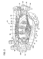
- FIG 2 is an internal perspective view of combustor 24 used in gas turbine engine 10, shown in Figure 1 .
- combustor 24 includes an annular combustion chamber 50 that is aligned substantially coaxially with engine longitudinal axis 15, and an inlet 52 and an outlet 54.
- Combustor 24 receives a stream of pressurized air discharged from compressor 22 (shown in Figure 1 ). A portion of the compressor discharge air flows into combustion chamber 50, wherein fuel injected from a fuel injector assembly 56 is mixed with the air to form a fuel-air mixture for combustion. Ignition of the fuel-air mixture is accomplished by a suitable igniter (not shown) and the resulting combustion gases are discharged towards an annular, first stage turbine inlet 58.
- Turbine inlet 58 defines an annular flow channel 59 that includes a plurality of circumferentially-spaced stator vanes 60 that channel the gas flow such that the flow impinges upon a plurality of first stage turbine blades 62 that are coupled to a first stage turbine disk 64.
- First stage turbine 26 rotates compressor 22, and one or more additional downstream stages (not shown) can be provided for driving booster 20 and fan rotor 36, as is shown in Figure 1 .
- combustion chamber 50 is housed within engine outer casing 66 and is defined by an annular combustor outer liner 68 and a radially-inwardly positioned annular combustor inner liner 70.
- a portion 72 of airflow channeled therethrough flows over an outermost surface of outer liner 68.
- a portion 74 of airflow channeled therein is directed into combustion chamber 50, wherein a portion 76 of the airflow is channeled over an innermost surface of inner liner 70.
- outer liner 68 and inner liner 70 include a plurality of annular step portions 80 that are defined by relatively short, inclined, outwardly-flaring annular panels 82 that include a plurality of circularly-spaced cooling air apertures 84 for use in allowing a portion of the air that flows along the outermost surfaces of outer and inner liners 68 and 70, respectively, to flow into the interior of combustion chamber 50.
- a plurality of axially-extending fuel injector assemblies 56 are positioned in a circular array at an upstream end of combustor 24 and extend into inlet 52 of annular combustion chamber 50. Upstream portions of outer and inner liners 68 and 70, respectively, are spaced radially from each other and define an outer cowl 86 and an inner cowl 88. The spacing between the forwardmost ends of cowls 86 and 88 define combustion chamber inlet 52 and provides an opening that enables compressor discharge air to enter combustion chamber 50.
- FIG 3 is an internal side view of an exemplary fuel nozzle assembly 89 used with combustion chamber 50 (shown in Figure 2 ).
- An annular combustion chamber 90 includes an annular combustor outer liner 92 and an annular combustor inner liner 94, and is positioned within an annular engine outer casing 96.
- Combustion chamber 90 is spaced inwardly from outer casing 96 such that outer liner 92 and outer casing 96 define a flow channel 98 for compressor discharge air to pass therethrough for cooling purposes.
- An upstream end 99 of combustion chamber 90 includes an annular dome 100 that includes a plurality of air entry holes (not shown) that channel compressor discharge air. Dome 100 extends inwardly and forwardly to a centerbody assembly 102.
- a cross-sectional area of combustion chamber 90 decreases to a smaller cross-sectional area at its downstream end 101 that is approximately the same size as a cross-sectional area of first stage turbine nozzle 104.
- An annular casing 106 is radially inward from inner liner 94 to cause air from compressor 22 (shown in Figure 1 ) to flow along combustor inner liner 94 to facilitate shielding other engine internal components, such as the engine drive shaft (not shown), from heat generated within combustion chamber 90.
- compressor discharge air flows to combustion chamber 90 through an annular duct 108 and into a diffuser section 110 having an enlarged cross-sectional area.
- Diffuser section 110 is immediately upstream from combustion chamber 90 and is in flow communication with outer flow channel 98, with an inner flow channel 112, and with centerbody assembly 102.
- approximately 60% of the compressor discharge air enters combustion chamber 90 through and around centerbody assembly 102, and the remaining compressor discharge air flows through outer flow channel 98 and through inner flow channel 112 and around combustion chamber 90 for use in cooling other combustor components.
- Centerbody assembly 102 is in flow communication with a source of pressurized fuel (not shown) via a fuel inlet 114.
- Centerbody assembly 102 is coupled to an engine outer casing 116.
- An igniter 118 is downstream from the centerbody assembly 102 and extends through outer casing 116 and into combustion chamber 90 to provide an initial ignition of the fuel-air mixture within combustion chamber 90.
- centerbody assembly 102 includes a central, primary combustion region 120 for ignition of fuel injected from a primary fuel injector 122, and an annular, secondary combustion region 124 for ignition of fuel injected from an annular, secondary fuel injector 126 that is spaced radially outward from primary fuel injector 122.
- twelve centerbody assemblies 102 are positioned in a circular array at an inlet 52 of the combustion chamber 90.
- any number of fuel nozzle assemblies may be positioned within combustion chamber 90 to enable gas turbine engine to function as described herein.
- Primary fuel injector 122 and secondary fuel injector 126 are received in a respective annular combustor dome 100 that extends from, and is coupled to, each of outer liner 92 and inner liner 94.
- An outer cowl 188 extends from a forward edge 95 of outer liner 92. Outer cowl 188 is extends arcuately towards fuel injector 122 and terminates at an outer cowl lip 188a. Similarly, an inner cowl 189 extends forwardly from a forward edge 97 of inner liner 94 and arcuately towards fuel injector 122. Inner cowl 189 terminates at an inner cowl lip 189a. Outer cowl lip 188a and inner cowl lip 189a are spaced radially from each other, relative to engine longitudinal axis 103, such that an annular opening 191 is defined through which compressor discharge air enters combustion chamber 90.
- FIG 4 is a schematic illustration of an exemplary centerbody assembly 102 that may be used in combustor 24 shown in Figure 2
- Figure 5 is a schematic illustration of centerbody assembly 102.
- Centerbody assembly 102 is received within combustor dome 100 and is positioned generally axisymmetrically about axis 103.
- centerbody assembly 102 includes a central, primary combustion region 120 and a surrounding, annular, secondary combustion region 124.
- Primary combustion region 120 includes primary fuel injector 122.
- Injector 122 is surrounded by a concentrically-aligned, primary annular member 130 such that an inner annular air conduit 132 is defined between member 130 and injector 122.
- Annular member 130 is radially outward from primary fuel injector 122 and is coupled thereto via a plurality of radially-extending inner swirl vanes 134.
- Swirl vanes 134 are inclined both radially and axially relative to axis 103 of centerbody assembly 102 to impart rotational movement to the compressor discharge air entering through inlet 138. More specifically, vanes 134 facilitate swirling air in a generally helical manner within conduit 132.
- Annular member 130 encloses primary fuel injector 122 and channels air around primary fuel injector 122 and through a first diffuser section 142 via an outwardly-flaring wall 144 of injector face 140.
- a second annular member 146 surrounds and is spaced radially outward from primary annular member 130.
- Member 146 includes an outer wall 148 and an inner wall 150.
- Inner wall 150 includes a first axially extending surface 152, an intermediate section 154, and an outwardly-diverging outer section 156 that terminates in a radially outwardly extending flange 158.
- Inner wall 150 and primary annular member 130 define an outer annular air conduit 160.
- Second annular member 146 is coupled to primary annular member 130 via a plurality of radially-extending outer swirl vanes 164 that are inclined both radially and axially relative to fuel nozzle assembly axis 103. Vanes 164 impart a rotational movement to compressor discharge air entering outer conduit 160 through inlet 166. More specifically, vanes 164 facilitate swirling the airflow in a generally helical manner as it flows through conduit 160.
- the rotational direction of the air stream within conduit 160 is the same as the rotational direction of the air stream within conduit 132.
- the rotational direction of the air streams may be in opposite rotational directions, depending on the fuel nozzle assembly size and configuration, as well as the operating conditions within a particular combustion chamber design.
- Annular member 146 defines an inner wall 150 of an annular housing 168 that includes a centerbody outer wall 170.
- Wall 170 includes an inner surface 172, and an outer surface 174, both of which extend to an end wall 176.
- air is channeled by annular conduit 178 to facilitate cooling inner surface 172. More specifically, and in the exemplary embodiment, air is channeled through a plurality of apertures 180 towards an air distribution region 182.
- a plurality of axially-extending apertures 184 are defined in end wall 176.
- apertures 184 have approximately the same diameter, and are staggered with respect to each other about end wall 176 such that a substantially uniform flow field is provided within gap 186 for use in cooling flange 158.
- apertures 184 may be positioned, sized and/or oriented to facilitate cooling centerbody assembly 102 as described herein. More specifically, in the exemplary embodiment, axially-extending apertures 184 are oriented to channel air directly towards an upstream surface 190 of flange 158.
- a plurality of inclined apertures 192 are defined in end wall 176.
- Apertures 192 are sized and oriented to channel air downstream and outwardly. More specifically, and in the exemplary embodiment, apertures 192 are oriented outwardly and rearwardly relative to fuel nozzle assembly axis 103 to channel air past flange 158 and towards an innermost portion of secondary combustion region 124 (shown in Figure 3 ). In the exemplary embodiment, apertures 192 are oriented relative to axis 103 at an angle of approximately 45°. Alternatively, apertures 192 may be oriented relative to axis 103 at an angle ranging from about 40° to about 50°.
- FIG 6 is a perspective view and Figure 7 is a side view of a baffle 200 used with centerbody assembly 102 (shown in Figure 5 ).
- baffle 200 is substantially arcuate and positioned adjacent to air distribution region 182 and radially inward from centerbody outer wall 170.
- Baffle 200 includes a plurality of air cooling apertures 202 for use in cooling the inner surface 172 with air channeled from conduit 178.
- Baffle 200 includes a first end 204 that has a first diameter D 1 and that extends from a body portion 205.
- Baffle 200 also includes an axially-opposite, outwardly-diverging second end 206 that has a second diameter D 2 .
- first diameter D 1 is smaller than second diameter D 2 .
- Baffle first end 204 is supported within air distribution region 182 by a flange 208 that extends inwardly from end wall 176 to provide additional support against flange 208 at a mating surface 213.
- mating surface 213 is a friction fit.
- mating surface 213 may be a bolted joint, a weld joint, and/or any joint arrangement that enables centerbody assembly 102 to function as described herein.
- baffle 200 includes an intermediate support 210 that extends radially inward to provide additional support against an internal support flange 212.
- air cooling apertures 202 have substantially the same diameter D 1 (as shown in Figure 5 ), and are circumferentially staggered with respect to each other about baffle 200 to provide a substantially uniform flow field within a gap 214 (shown in Figure 5 ).
- Apertures 202 facilitate cooling centerbody outer wall 170 and, more specifically inner surface 172.
- apertures 202 may be positioned, sized and/or oriented in any configuration that facilitates cooling centerbody assembly as described herein.
- a second plurality of apertures 220 are defined in baffle 200 and are positioned axially upstream from apertures 202.
- Apertures 220 are oriented outwardly and forwardly relative to fuel nozzle assembly axis 103 and channel air upstream and in an outward direction. More specifically, apertures 220 are sized and oriented to channel air into gap 214 for use in cooling centerbody outer wall 170 and more specifically inner surface 172, as described herein. Air is channeled from gap 214 via apertures 192, as described in more detail herein.
- FIG 8 is a schematic illustration of an alternative baffle 300 that may be used with the centerbody assembly 102 (shown in Figure 4 ).
- a centerbody outerwall 302 houses a substantially annular member 304 therein.
- Member 304 extends generally axially outward to an outwardly-diverging outer section 306 that terminates in a radially outwardly extending flange 308.
- air is channeled via an annular conduit 310 to facilitate cooling an inner surface 312 of centerbody outer wall 302 and flange 308.
- a plurality of generally axially-extending cooling air apertures 314 are defined in a baffle end wall 316.
- apertures 314 are sized and oriented to provide a substantially uniform flow field for use in cooling flange 308.
- Apertures 314 have approximately the same diameter D 3 , and are circumferentially staggered about end wall 316.
- An intermediate flange 318 is radially outward from apertures 314 and extends upstream from baffle end wall 316.
- a plurality of radially-extending air cooling apertures 320 are defined in flange 318.
- Apertures 320 have approximately the same diameter, and are circumferentially staggered about intermediate flange 318 to provide a substantially uniform flow field for use in cooling centerbody outer wall 302, and more specifically, for cooling inner surface 312.
- a plurality of outer cooling apertures 322 are defined in end wall 316.
- Apertures 322 are sized and oriented to channel air downstream and outwardly.
- apertures 322 are oriented outwardly and rearwardly relative to fuel nozzle assembly axis 103 to provide a plurality of air jets that channel air past flange 308 and towards an innermost portion of a combustion region (not shown). More specifically, apertures 322 are obliquely oriented relative to axis 103 of centerbody assembly 102 at an angle of approximately 45°. Alternatively, apertures 322 may be oriented at an angle of about 40° to about 50° relative to axis 103.
- Baffle 300 is coupled to centerbody outer wall 302 at a joint 326.
- joint 326 is a welded joint.
- baffle 300 is coupled to centerbody outer wall 302 in any configuration that enables combustor to function as described herein.
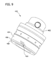
- FIG. 9 is a side elevation view of an alternative centerbody cooling system 400 that may be used with a centerbody 402.
- Centerbody 402 includes an annular outer wall 404 that extends to an end wall 406 and a flange 408.
- centerbody 402 includes an internal impingement cooling system (not shown) as described herein.
- centerbody 402 does not include the internal impingement cooling system.
- Centerbody 402 includes a plurality of generally radially-extending cooling air apertures 410 that extend through outer wall 404.
- apertures 410 are sized and oriented to provide a substantially uniform flow field from an internal area of centerbody 402, for example gap 214 (shown in Figure 5 ), towards a boundary layer (not shown) that is adjacent to centerbody outer wall 404. More specifically, apertures 410 are generally aligned with the direction of swirl of air flow about the centerbody 402. In the illustrated embodiment, apertures 410 are spaced to facilitate reducing local hot-spots or distressed regions of centerbody outer wall 404 during structural testing. Additionally, the quantity of apertures provided at each location is at least partially based on an amount of airflow within the centerbody 402 (as described herein) as well as local pressure constraints for the selected location on the centerbody outer wall 404. The illustrated embodiment facilitates substantially evacuating any residual fuel or flame that may linger adjacent to centerbody outer wall 404, such that the potential for flashback or auto-ignition is facilitated being substantially reduced.
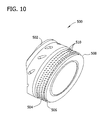
- FIG 10 is a perspective view of an alternative centerbody cooling system 500 that may be used with a centerbody 502.
- Centerbody 502 includes an annular outer wall 504 that extends to an end wall 506 and a flange 508.
- centerbody 502 includes an internal impingement cooling system (not shown).
- centerbody 502 does not include the internal impingement cooling system.
- Centerbody 502 includes a plurality of generally radially-extending cooling air apertures 510 that extend through outer wall 504.
- apertures 510 are sized and oriented to provide a substantially uniform flow field from an internal area of centerbody 502, for example, from gap 214 (shown in Figure 5 ), towards to a boundary layer (not shown) adjacent to centerbody outer wall 504.
- apertures 510 are generally aligned with the direction of swirl of air flow about centerbody 502. Such a flow pattern provides additional cooling to the centerbody outer wall 504 as well as evacuates any residual fuel or flame that may linger adjacent to centerbody outer wall 504. As such, apertures 510 thereby substantially reduce the potential for flashback or auto-ignition, while providing additional cooling to centerbody outer wall 504.
- centerbody cooling assemblies for use in gas turbine engines are described in detail above.
- the above-described cooling assemblies use impingement cooling methods to facilitate reducing the operating temperatures of centerbody walls and to facilitate evacuation of residual fuel from the vicinity of the centerbody by channeling a stream of air through apertures oriented and positioned to cool the internal surfaces of the combustor centerbody.
- Such results are accomplished without disrupting the aerodynamic features of the fuel-mixing system and without creating a substantial pressure change about the centerbody.
- a potential for auto-ignition or flashback exists in turbine engines where air and fuel are pre-mixed.
- the addition of fuel nozzle centerbodies in known engines increases the risk of auto-ignition, flashback or detonation is increased.
- the cooling assemblies described herein substantially reduce local heating resulting from a flashback or auto-ignition incident, and reduce centerbody surface temperatures away from these local hot-spots or distressed regions of the centerbody. Such a reduction in temperature substantially reduces the likelihood of flashback or auto-ignition occurrences. Additionally, the cooling assemblies described herein facilitate evacuating fuel from the proximity of the centerbody to further reduce the potential for auto-ignition and flashback.
Landscapes
- Engineering & Computer Science (AREA)
- Chemical & Material Sciences (AREA)
- Combustion & Propulsion (AREA)
- Mechanical Engineering (AREA)
- General Engineering & Computer Science (AREA)
- Turbine Rotor Nozzle Sealing (AREA)
Applications Claiming Priority (1)
| Application Number | Priority Date | Filing Date | Title |
|---|---|---|---|
| US12/176,898 US8555645B2 (en) | 2008-07-21 | 2008-07-21 | Fuel nozzle centerbody and method of assembling the same |
Publications (2)
| Publication Number | Publication Date |
|---|---|
| EP2148141A2 true EP2148141A2 (de) | 2010-01-27 |
| EP2148141A3 EP2148141A3 (de) | 2017-06-07 |
Family
ID=41210284
Family Applications (1)
| Application Number | Title | Priority Date | Filing Date |
|---|---|---|---|
| EP09165583.7A Withdrawn EP2148141A3 (de) | 2008-07-21 | 2009-07-15 | Brennstoffdüsenkegel und Verfahren zu dessen Montage |
Country Status (4)
| Country | Link |
|---|---|
| US (1) | US8555645B2 (de) |
| EP (1) | EP2148141A3 (de) |
| JP (1) | JP5507139B2 (de) |
| CA (1) | CA2672502C (de) |
Cited By (1)
| Publication number | Priority date | Publication date | Assignee | Title |
|---|---|---|---|---|
| EP3306194A1 (de) * | 2016-10-06 | 2018-04-11 | Ansaldo Energia IP UK Limited | Brennkammerwandelement und verfahren zur herstellung davon |
Families Citing this family (10)
| Publication number | Priority date | Publication date | Assignee | Title |
|---|---|---|---|---|
| DE102007050276A1 (de) * | 2007-10-18 | 2009-04-23 | Rolls-Royce Deutschland Ltd & Co Kg | Magervormischbrenner für ein Gasturbinentriebwerk |
| US20120151928A1 (en) * | 2010-12-17 | 2012-06-21 | Nayan Vinodbhai Patel | Cooling flowpath dirt deflector in fuel nozzle |
| JP5924618B2 (ja) * | 2012-06-07 | 2016-05-25 | 川崎重工業株式会社 | 燃料噴射装置 |
| US9453461B2 (en) * | 2014-12-23 | 2016-09-27 | General Electric Company | Fuel nozzle structure |
| US9803552B2 (en) | 2015-10-30 | 2017-10-31 | General Electric Company | Turbine engine fuel injection system and methods of assembling the same |
| US10724741B2 (en) | 2016-05-10 | 2020-07-28 | General Electric Company | Combustors and methods of assembling the same |
| US10775048B2 (en) | 2017-03-15 | 2020-09-15 | General Electric Company | Fuel nozzle for a gas turbine engine |
| US10739006B2 (en) | 2017-03-15 | 2020-08-11 | General Electric Company | Fuel nozzle for a gas turbine engine |
| US11371700B2 (en) * | 2020-07-15 | 2022-06-28 | Raytheon Technologies Corporation | Deflector for conduit inlet within a combustor section plenum |
| US11592177B2 (en) * | 2021-04-16 | 2023-02-28 | General Electric Company | Purging configuration for combustor mixing assembly |
Family Cites Families (14)
| Publication number | Priority date | Publication date | Assignee | Title |
|---|---|---|---|---|
| US5097666A (en) * | 1989-12-11 | 1992-03-24 | Sundstrand Corporation | Combustor fuel injection system |
| US5826423A (en) * | 1996-11-13 | 1998-10-27 | Solar Turbines Incorporated | Dual fuel injection method and apparatus with multiple air blast liquid fuel atomizers |
| US5908160A (en) | 1996-12-20 | 1999-06-01 | United Technologies Corporation | Centerbody for a two stream tangential entry nozzle |
| EP0986717A1 (de) | 1997-06-02 | 2000-03-22 | Solar Turbines Incorporated | Einspritzverfahren und vorrichtung für zwei brennstoffe |
| US6141967A (en) | 1998-01-09 | 2000-11-07 | General Electric Company | Air fuel mixer for gas turbine combustor |
| US6227798B1 (en) | 1999-11-30 | 2001-05-08 | General Electric Company | Turbine nozzle segment band cooling |
| US6389815B1 (en) | 2000-09-08 | 2002-05-21 | General Electric Company | Fuel nozzle assembly for reduced exhaust emissions |
| US7024861B2 (en) * | 2002-12-20 | 2006-04-11 | Martling Vincent C | Fully premixed pilotless secondary fuel nozzle with improved tip cooling |
| US7181915B2 (en) | 2002-12-31 | 2007-02-27 | General Electric Company | High temperature centerbody for temperature reduction by optical reflection and process for manufacturing |
| US6898938B2 (en) * | 2003-04-24 | 2005-05-31 | General Electric Company | Differential pressure induced purging fuel injector with asymmetric cyclone |
| US7007477B2 (en) | 2004-06-03 | 2006-03-07 | General Electric Company | Premixing burner with impingement cooled centerbody and method of cooling centerbody |
| US20070074518A1 (en) * | 2005-09-30 | 2007-04-05 | Solar Turbines Incorporated | Turbine engine having acoustically tuned fuel nozzle |
| FR2893390B1 (fr) * | 2005-11-15 | 2011-04-01 | Snecma | Fond de chambre de combustion avec ventilation |
| US20100251719A1 (en) * | 2006-12-29 | 2010-10-07 | Alfred Albert Mancini | Centerbody for mixer assembly of a gas turbine engine combustor |
-
2008
- 2008-07-21 US US12/176,898 patent/US8555645B2/en active Active
-
2009
- 2009-07-15 EP EP09165583.7A patent/EP2148141A3/de not_active Withdrawn
- 2009-07-16 CA CA2672502A patent/CA2672502C/en not_active Expired - Fee Related
- 2009-07-16 JP JP2009167339A patent/JP5507139B2/ja not_active Expired - Fee Related
Cited By (1)
| Publication number | Priority date | Publication date | Assignee | Title |
|---|---|---|---|---|
| EP3306194A1 (de) * | 2016-10-06 | 2018-04-11 | Ansaldo Energia IP UK Limited | Brennkammerwandelement und verfahren zur herstellung davon |
Also Published As
| Publication number | Publication date |
|---|---|
| JP2010025109A (ja) | 2010-02-04 |
| EP2148141A3 (de) | 2017-06-07 |
| CA2672502A1 (en) | 2010-01-21 |
| JP5507139B2 (ja) | 2014-05-28 |
| CA2672502C (en) | 2016-10-18 |
| US20100012750A1 (en) | 2010-01-21 |
| US8555645B2 (en) | 2013-10-15 |
Similar Documents
| Publication | Publication Date | Title |
|---|---|---|
| CA2672502C (en) | Fuel nozzle centerbody and method of assembling the same | |
| US8171735B2 (en) | Mixer assembly for gas turbine engine combustor | |
| EP2330350B1 (de) | Doppelwandige Flammrohre mit prallgekühlten Zündern | |
| EP1186832B1 (de) | Brennstoffeinspritzdüsenanordnung zur Verminderung von Abgasemissionen | |
| US7762073B2 (en) | Pilot mixer for mixer assembly of a gas turbine engine combustor having a primary fuel injector and a plurality of secondary fuel injection ports | |
| US20100251719A1 (en) | Centerbody for mixer assembly of a gas turbine engine combustor | |
| EP3220047B1 (de) | Gasturbinenstromhülsenhalterung | |
| EP3220055A1 (de) | Axial gestufte kraftstoffeinspritzanordnung | |
| KR101774630B1 (ko) | 가스 터빈 엔진에 사용되는 예비혼합된 연료와 공기를 가진 접선방향의 애뉼러형 연소실 | |
| EP2806217B1 (de) | Gasturbinenmotoren mit Einspritzanordnungen | |
| US11280495B2 (en) | Gas turbine combustor fuel injector flow device including vanes | |
| CN115388426B (zh) | 用于燃油喷嘴的隔热罩 | |
| US11994295B2 (en) | Multi pressure drop swirler ferrule plate | |
| EP3434980B1 (de) | Umlenkbrennkammer | |
| GB2451517A (en) | Pilot mixer for mixer assembly of a gas turbine engine combustor having a primary fuel injector and a plurality of secondary fuel injection ports | |
| EP2045527B1 (de) | Facettierte Kuppelanordnungen für Gasturbinen-Verbrennungsmotoren | |
| US12292194B2 (en) | Ignitor housing for a combustor of a gas turbine | |
| CA2597846A1 (en) | Pilot fuel injector for mixer assembly of a high pressure gas turbine engine | |
| US12286932B1 (en) | Turbine engine combustor including a heat shield | |
| US12270542B2 (en) | Combustor liner with shield holes | |
| CA2596789C (en) | Pilot mixer for mixer assembly of a gas turbine engine combustor having a primary fuel injector and a plurality of secondary fuel injection ports | |
| CA2572044A1 (en) | Combustor construction |
Legal Events
| Date | Code | Title | Description |
|---|---|---|---|
| PUAI | Public reference made under article 153(3) epc to a published international application that has entered the european phase |
Free format text: ORIGINAL CODE: 0009012 |
|
| AK | Designated contracting states |
Kind code of ref document: A2 Designated state(s): AT BE BG CH CY CZ DE DK EE ES FI FR GB GR HR HU IE IS IT LI LT LU LV MC MK MT NL NO PL PT RO SE SI SK SM TR |
|
| PUAL | Search report despatched |
Free format text: ORIGINAL CODE: 0009013 |
|
| AK | Designated contracting states |
Kind code of ref document: A3 Designated state(s): AT BE BG CH CY CZ DE DK EE ES FI FR GB GR HR HU IE IS IT LI LT LU LV MC MK MT NL NO PL PT RO SE SI SK SM TR |
|
| RIC1 | Information provided on ipc code assigned before grant |
Ipc: F23R 3/14 20060101AFI20170428BHEP Ipc: F23R 3/28 20060101ALI20170428BHEP |
|
| PUAL | Search report despatched |
Free format text: ORIGINAL CODE: 0009013 |
|
| STAA | Information on the status of an ep patent application or granted ep patent |
Free format text: STATUS: THE APPLICATION HAS BEEN PUBLISHED |
|
| STAA | Information on the status of an ep patent application or granted ep patent |
Free format text: STATUS: THE APPLICATION IS DEEMED TO BE WITHDRAWN |
|
| 18D | Application deemed to be withdrawn |
Effective date: 20171208 |