EP2148127A2 - Storage device for compressed media and method for filling the tank of vehicles - Google Patents
Storage device for compressed media and method for filling the tank of vehicles Download PDFInfo
- Publication number
- EP2148127A2 EP2148127A2 EP09006295A EP09006295A EP2148127A2 EP 2148127 A2 EP2148127 A2 EP 2148127A2 EP 09006295 A EP09006295 A EP 09006295A EP 09006295 A EP09006295 A EP 09006295A EP 2148127 A2 EP2148127 A2 EP 2148127A2
- Authority
- EP
- European Patent Office
- Prior art keywords
- container
- storage device
- storage
- hydrogen
- vehicle
- Prior art date
- Legal status (The legal status is an assumption and is not a legal conclusion. Google has not performed a legal analysis and makes no representation as to the accuracy of the status listed.)
- Withdrawn
Links
Images

Classifications
-
- F—MECHANICAL ENGINEERING; LIGHTING; HEATING; WEAPONS; BLASTING
- F17—STORING OR DISTRIBUTING GASES OR LIQUIDS
- F17C—VESSELS FOR CONTAINING OR STORING COMPRESSED, LIQUEFIED OR SOLIDIFIED GASES; FIXED-CAPACITY GAS-HOLDERS; FILLING VESSELS WITH, OR DISCHARGING FROM VESSELS, COMPRESSED, LIQUEFIED, OR SOLIDIFIED GASES
- F17C13/00—Details of vessels or of the filling or discharging of vessels
- F17C13/08—Mounting arrangements for vessels
- F17C13/083—Mounting arrangements for vessels for medium-sized mobile storage vessels, e.g. tank vehicles or railway tank vehicles
-
- F—MECHANICAL ENGINEERING; LIGHTING; HEATING; WEAPONS; BLASTING
- F17—STORING OR DISTRIBUTING GASES OR LIQUIDS
- F17C—VESSELS FOR CONTAINING OR STORING COMPRESSED, LIQUEFIED OR SOLIDIFIED GASES; FIXED-CAPACITY GAS-HOLDERS; FILLING VESSELS WITH, OR DISCHARGING FROM VESSELS, COMPRESSED, LIQUEFIED, OR SOLIDIFIED GASES
- F17C5/00—Methods or apparatus for filling containers with liquefied, solidified, or compressed gases under pressures
- F17C5/06—Methods or apparatus for filling containers with liquefied, solidified, or compressed gases under pressures for filling with compressed gases
-
- B—PERFORMING OPERATIONS; TRANSPORTING
- B60—VEHICLES IN GENERAL
- B60P—VEHICLES ADAPTED FOR LOAD TRANSPORTATION OR TO TRANSPORT, TO CARRY, OR TO COMPRISE SPECIAL LOADS OR OBJECTS
- B60P1/00—Vehicles predominantly for transporting loads and modified to facilitate loading, consolidating the load, or unloading
-
- F—MECHANICAL ENGINEERING; LIGHTING; HEATING; WEAPONS; BLASTING
- F17—STORING OR DISTRIBUTING GASES OR LIQUIDS
- F17C—VESSELS FOR CONTAINING OR STORING COMPRESSED, LIQUEFIED OR SOLIDIFIED GASES; FIXED-CAPACITY GAS-HOLDERS; FILLING VESSELS WITH, OR DISCHARGING FROM VESSELS, COMPRESSED, LIQUEFIED, OR SOLIDIFIED GASES
- F17C1/00—Pressure vessels, e.g. gas cylinder, gas tank, replaceable cartridge
-
- F—MECHANICAL ENGINEERING; LIGHTING; HEATING; WEAPONS; BLASTING
- F17—STORING OR DISTRIBUTING GASES OR LIQUIDS
- F17C—VESSELS FOR CONTAINING OR STORING COMPRESSED, LIQUEFIED OR SOLIDIFIED GASES; FIXED-CAPACITY GAS-HOLDERS; FILLING VESSELS WITH, OR DISCHARGING FROM VESSELS, COMPRESSED, LIQUEFIED, OR SOLIDIFIED GASES
- F17C2201/00—Vessel construction, in particular geometry, arrangement or size
- F17C2201/01—Shape
- F17C2201/0104—Shape cylindrical
-
- F—MECHANICAL ENGINEERING; LIGHTING; HEATING; WEAPONS; BLASTING
- F17—STORING OR DISTRIBUTING GASES OR LIQUIDS
- F17C—VESSELS FOR CONTAINING OR STORING COMPRESSED, LIQUEFIED OR SOLIDIFIED GASES; FIXED-CAPACITY GAS-HOLDERS; FILLING VESSELS WITH, OR DISCHARGING FROM VESSELS, COMPRESSED, LIQUEFIED, OR SOLIDIFIED GASES
- F17C2203/00—Vessel construction, in particular walls or details thereof
- F17C2203/06—Materials for walls or layers thereof; Properties or structures of walls or their materials
- F17C2203/0634—Materials for walls or layers thereof
- F17C2203/0658—Synthetics
- F17C2203/0663—Synthetics in form of fibers or filaments
-
- F—MECHANICAL ENGINEERING; LIGHTING; HEATING; WEAPONS; BLASTING
- F17—STORING OR DISTRIBUTING GASES OR LIQUIDS
- F17C—VESSELS FOR CONTAINING OR STORING COMPRESSED, LIQUEFIED OR SOLIDIFIED GASES; FIXED-CAPACITY GAS-HOLDERS; FILLING VESSELS WITH, OR DISCHARGING FROM VESSELS, COMPRESSED, LIQUEFIED, OR SOLIDIFIED GASES
- F17C2205/00—Vessel construction, in particular mounting arrangements, attachments or identifications means
- F17C2205/01—Mounting arrangements
- F17C2205/0103—Exterior arrangements
- F17C2205/0111—Boxes
-
- F—MECHANICAL ENGINEERING; LIGHTING; HEATING; WEAPONS; BLASTING
- F17—STORING OR DISTRIBUTING GASES OR LIQUIDS
- F17C—VESSELS FOR CONTAINING OR STORING COMPRESSED, LIQUEFIED OR SOLIDIFIED GASES; FIXED-CAPACITY GAS-HOLDERS; FILLING VESSELS WITH, OR DISCHARGING FROM VESSELS, COMPRESSED, LIQUEFIED, OR SOLIDIFIED GASES
- F17C2205/00—Vessel construction, in particular mounting arrangements, attachments or identifications means
- F17C2205/01—Mounting arrangements
- F17C2205/0123—Mounting arrangements characterised by number of vessels
- F17C2205/013—Two or more vessels
- F17C2205/0134—Two or more vessels characterised by the presence of fluid connection between vessels
- F17C2205/0146—Two or more vessels characterised by the presence of fluid connection between vessels with details of the manifold
-
- F—MECHANICAL ENGINEERING; LIGHTING; HEATING; WEAPONS; BLASTING
- F17—STORING OR DISTRIBUTING GASES OR LIQUIDS
- F17C—VESSELS FOR CONTAINING OR STORING COMPRESSED, LIQUEFIED OR SOLIDIFIED GASES; FIXED-CAPACITY GAS-HOLDERS; FILLING VESSELS WITH, OR DISCHARGING FROM VESSELS, COMPRESSED, LIQUEFIED, OR SOLIDIFIED GASES
- F17C2205/00—Vessel construction, in particular mounting arrangements, attachments or identifications means
- F17C2205/01—Mounting arrangements
- F17C2205/0153—Details of mounting arrangements
- F17C2205/0157—Details of mounting arrangements for transport
-
- F—MECHANICAL ENGINEERING; LIGHTING; HEATING; WEAPONS; BLASTING
- F17—STORING OR DISTRIBUTING GASES OR LIQUIDS
- F17C—VESSELS FOR CONTAINING OR STORING COMPRESSED, LIQUEFIED OR SOLIDIFIED GASES; FIXED-CAPACITY GAS-HOLDERS; FILLING VESSELS WITH, OR DISCHARGING FROM VESSELS, COMPRESSED, LIQUEFIED, OR SOLIDIFIED GASES
- F17C2205/00—Vessel construction, in particular mounting arrangements, attachments or identifications means
- F17C2205/01—Mounting arrangements
- F17C2205/0153—Details of mounting arrangements
- F17C2205/0176—Details of mounting arrangements with ventilation
-
- F—MECHANICAL ENGINEERING; LIGHTING; HEATING; WEAPONS; BLASTING
- F17—STORING OR DISTRIBUTING GASES OR LIQUIDS
- F17C—VESSELS FOR CONTAINING OR STORING COMPRESSED, LIQUEFIED OR SOLIDIFIED GASES; FIXED-CAPACITY GAS-HOLDERS; FILLING VESSELS WITH, OR DISCHARGING FROM VESSELS, COMPRESSED, LIQUEFIED, OR SOLIDIFIED GASES
- F17C2205/00—Vessel construction, in particular mounting arrangements, attachments or identifications means
- F17C2205/03—Fluid connections, filters, valves, closure means or other attachments
- F17C2205/0302—Fittings, valves, filters, or components in connection with the gas storage device
- F17C2205/0323—Valves
-
- F—MECHANICAL ENGINEERING; LIGHTING; HEATING; WEAPONS; BLASTING
- F17—STORING OR DISTRIBUTING GASES OR LIQUIDS
- F17C—VESSELS FOR CONTAINING OR STORING COMPRESSED, LIQUEFIED OR SOLIDIFIED GASES; FIXED-CAPACITY GAS-HOLDERS; FILLING VESSELS WITH, OR DISCHARGING FROM VESSELS, COMPRESSED, LIQUEFIED, OR SOLIDIFIED GASES
- F17C2221/00—Handled fluid, in particular type of fluid
- F17C2221/01—Pure fluids
- F17C2221/012—Hydrogen
-
- F—MECHANICAL ENGINEERING; LIGHTING; HEATING; WEAPONS; BLASTING
- F17—STORING OR DISTRIBUTING GASES OR LIQUIDS
- F17C—VESSELS FOR CONTAINING OR STORING COMPRESSED, LIQUEFIED OR SOLIDIFIED GASES; FIXED-CAPACITY GAS-HOLDERS; FILLING VESSELS WITH, OR DISCHARGING FROM VESSELS, COMPRESSED, LIQUEFIED, OR SOLIDIFIED GASES
- F17C2221/00—Handled fluid, in particular type of fluid
- F17C2221/01—Pure fluids
- F17C2221/014—Nitrogen
-
- F—MECHANICAL ENGINEERING; LIGHTING; HEATING; WEAPONS; BLASTING
- F17—STORING OR DISTRIBUTING GASES OR LIQUIDS
- F17C—VESSELS FOR CONTAINING OR STORING COMPRESSED, LIQUEFIED OR SOLIDIFIED GASES; FIXED-CAPACITY GAS-HOLDERS; FILLING VESSELS WITH, OR DISCHARGING FROM VESSELS, COMPRESSED, LIQUEFIED, OR SOLIDIFIED GASES
- F17C2223/00—Handled fluid before transfer, i.e. state of fluid when stored in the vessel or before transfer from the vessel
- F17C2223/01—Handled fluid before transfer, i.e. state of fluid when stored in the vessel or before transfer from the vessel characterised by the phase
- F17C2223/0107—Single phase
- F17C2223/0123—Single phase gaseous, e.g. CNG, GNC
-
- F—MECHANICAL ENGINEERING; LIGHTING; HEATING; WEAPONS; BLASTING
- F17—STORING OR DISTRIBUTING GASES OR LIQUIDS
- F17C—VESSELS FOR CONTAINING OR STORING COMPRESSED, LIQUEFIED OR SOLIDIFIED GASES; FIXED-CAPACITY GAS-HOLDERS; FILLING VESSELS WITH, OR DISCHARGING FROM VESSELS, COMPRESSED, LIQUEFIED, OR SOLIDIFIED GASES
- F17C2223/00—Handled fluid before transfer, i.e. state of fluid when stored in the vessel or before transfer from the vessel
- F17C2223/03—Handled fluid before transfer, i.e. state of fluid when stored in the vessel or before transfer from the vessel characterised by the pressure level
- F17C2223/036—Very high pressure (>80 bar)
-
- F—MECHANICAL ENGINEERING; LIGHTING; HEATING; WEAPONS; BLASTING
- F17—STORING OR DISTRIBUTING GASES OR LIQUIDS
- F17C—VESSELS FOR CONTAINING OR STORING COMPRESSED, LIQUEFIED OR SOLIDIFIED GASES; FIXED-CAPACITY GAS-HOLDERS; FILLING VESSELS WITH, OR DISCHARGING FROM VESSELS, COMPRESSED, LIQUEFIED, OR SOLIDIFIED GASES
- F17C2225/00—Handled fluid after transfer, i.e. state of fluid after transfer from the vessel
- F17C2225/01—Handled fluid after transfer, i.e. state of fluid after transfer from the vessel characterised by the phase
- F17C2225/0107—Single phase
- F17C2225/0123—Single phase gaseous, e.g. CNG, GNC
-
- F—MECHANICAL ENGINEERING; LIGHTING; HEATING; WEAPONS; BLASTING
- F17—STORING OR DISTRIBUTING GASES OR LIQUIDS
- F17C—VESSELS FOR CONTAINING OR STORING COMPRESSED, LIQUEFIED OR SOLIDIFIED GASES; FIXED-CAPACITY GAS-HOLDERS; FILLING VESSELS WITH, OR DISCHARGING FROM VESSELS, COMPRESSED, LIQUEFIED, OR SOLIDIFIED GASES
- F17C2225/00—Handled fluid after transfer, i.e. state of fluid after transfer from the vessel
- F17C2225/03—Handled fluid after transfer, i.e. state of fluid after transfer from the vessel characterised by the pressure level
- F17C2225/036—Very high pressure, i.e. above 80 bars
-
- F—MECHANICAL ENGINEERING; LIGHTING; HEATING; WEAPONS; BLASTING
- F17—STORING OR DISTRIBUTING GASES OR LIQUIDS
- F17C—VESSELS FOR CONTAINING OR STORING COMPRESSED, LIQUEFIED OR SOLIDIFIED GASES; FIXED-CAPACITY GAS-HOLDERS; FILLING VESSELS WITH, OR DISCHARGING FROM VESSELS, COMPRESSED, LIQUEFIED, OR SOLIDIFIED GASES
- F17C2227/00—Transfer of fluids, i.e. method or means for transferring the fluid; Heat exchange with the fluid
- F17C2227/01—Propulsion of the fluid
- F17C2227/0128—Propulsion of the fluid with pumps or compressors
- F17C2227/0171—Arrangement
- F17C2227/0185—Arrangement comprising several pumps or compressors
-
- F—MECHANICAL ENGINEERING; LIGHTING; HEATING; WEAPONS; BLASTING
- F17—STORING OR DISTRIBUTING GASES OR LIQUIDS
- F17C—VESSELS FOR CONTAINING OR STORING COMPRESSED, LIQUEFIED OR SOLIDIFIED GASES; FIXED-CAPACITY GAS-HOLDERS; FILLING VESSELS WITH, OR DISCHARGING FROM VESSELS, COMPRESSED, LIQUEFIED, OR SOLIDIFIED GASES
- F17C2227/00—Transfer of fluids, i.e. method or means for transferring the fluid; Heat exchange with the fluid
- F17C2227/03—Heat exchange with the fluid
- F17C2227/0337—Heat exchange with the fluid by cooling
- F17C2227/0341—Heat exchange with the fluid by cooling using another fluid
-
- F—MECHANICAL ENGINEERING; LIGHTING; HEATING; WEAPONS; BLASTING
- F17—STORING OR DISTRIBUTING GASES OR LIQUIDS
- F17C—VESSELS FOR CONTAINING OR STORING COMPRESSED, LIQUEFIED OR SOLIDIFIED GASES; FIXED-CAPACITY GAS-HOLDERS; FILLING VESSELS WITH, OR DISCHARGING FROM VESSELS, COMPRESSED, LIQUEFIED, OR SOLIDIFIED GASES
- F17C2227/00—Transfer of fluids, i.e. method or means for transferring the fluid; Heat exchange with the fluid
- F17C2227/04—Methods for emptying or filling
- F17C2227/043—Methods for emptying or filling by pressure cascade
-
- F—MECHANICAL ENGINEERING; LIGHTING; HEATING; WEAPONS; BLASTING
- F17—STORING OR DISTRIBUTING GASES OR LIQUIDS
- F17C—VESSELS FOR CONTAINING OR STORING COMPRESSED, LIQUEFIED OR SOLIDIFIED GASES; FIXED-CAPACITY GAS-HOLDERS; FILLING VESSELS WITH, OR DISCHARGING FROM VESSELS, COMPRESSED, LIQUEFIED, OR SOLIDIFIED GASES
- F17C2265/00—Effects achieved by gas storage or gas handling
- F17C2265/06—Fluid distribution
- F17C2265/065—Fluid distribution for refueling vehicle fuel tanks
-
- F—MECHANICAL ENGINEERING; LIGHTING; HEATING; WEAPONS; BLASTING
- F17—STORING OR DISTRIBUTING GASES OR LIQUIDS
- F17C—VESSELS FOR CONTAINING OR STORING COMPRESSED, LIQUEFIED OR SOLIDIFIED GASES; FIXED-CAPACITY GAS-HOLDERS; FILLING VESSELS WITH, OR DISCHARGING FROM VESSELS, COMPRESSED, LIQUEFIED, OR SOLIDIFIED GASES
- F17C2265/00—Effects achieved by gas storage or gas handling
- F17C2265/07—Generating electrical power as side effect
-
- F—MECHANICAL ENGINEERING; LIGHTING; HEATING; WEAPONS; BLASTING
- F17—STORING OR DISTRIBUTING GASES OR LIQUIDS
- F17C—VESSELS FOR CONTAINING OR STORING COMPRESSED, LIQUEFIED OR SOLIDIFIED GASES; FIXED-CAPACITY GAS-HOLDERS; FILLING VESSELS WITH, OR DISCHARGING FROM VESSELS, COMPRESSED, LIQUEFIED, OR SOLIDIFIED GASES
- F17C2270/00—Applications
- F17C2270/01—Applications for fluid transport or storage
- F17C2270/0165—Applications for fluid transport or storage on the road
- F17C2270/0168—Applications for fluid transport or storage on the road by vehicles
- F17C2270/0171—Trucks
-
- F—MECHANICAL ENGINEERING; LIGHTING; HEATING; WEAPONS; BLASTING
- F17—STORING OR DISTRIBUTING GASES OR LIQUIDS
- F17C—VESSELS FOR CONTAINING OR STORING COMPRESSED, LIQUEFIED OR SOLIDIFIED GASES; FIXED-CAPACITY GAS-HOLDERS; FILLING VESSELS WITH, OR DISCHARGING FROM VESSELS, COMPRESSED, LIQUEFIED, OR SOLIDIFIED GASES
- F17C2270/00—Applications
- F17C2270/01—Applications for fluid transport or storage
- F17C2270/0165—Applications for fluid transport or storage on the road
- F17C2270/0168—Applications for fluid transport or storage on the road by vehicles
- F17C2270/0173—Railways
-
- Y—GENERAL TAGGING OF NEW TECHNOLOGICAL DEVELOPMENTS; GENERAL TAGGING OF CROSS-SECTIONAL TECHNOLOGIES SPANNING OVER SEVERAL SECTIONS OF THE IPC; TECHNICAL SUBJECTS COVERED BY FORMER USPC CROSS-REFERENCE ART COLLECTIONS [XRACs] AND DIGESTS
- Y02—TECHNOLOGIES OR APPLICATIONS FOR MITIGATION OR ADAPTATION AGAINST CLIMATE CHANGE
- Y02E—REDUCTION OF GREENHOUSE GAS [GHG] EMISSIONS, RELATED TO ENERGY GENERATION, TRANSMISSION OR DISTRIBUTION
- Y02E60/00—Enabling technologies; Technologies with a potential or indirect contribution to GHG emissions mitigation
- Y02E60/30—Hydrogen technology
- Y02E60/32—Hydrogen storage
Definitions
- the invention relates to a storage device for storing a compressed medium, such as hydrogen.
- the invention relates to a method for refueling a vehicle with gaseous hydrogen by means of a variable mit step method.
- vehicle below all types of land, air and water vehicles are to be understood, in which a refueling with a compressed medium, in particular with hydrogen, can be realized.
- medium below u. a. To understand gases and gas mixtures.
- the supply of consumers or customers with compressed media such as the supply of hydrogen gas stations with compressed gaseous hydrogen, the supply of customers of various kinds with compressed, gaseous nitrogen, etc. is currently realized by the compressed media in Compressed gas cylinders, in liquid tanks or by means of so-called. High-pressure trailer to be delivered.
- the supply of hydrogen filling stations with compressed, gaseous hydrogen is relatively expensive. The reason for this is that the hydrogen is liquefied prior to transport, transported in the liquefied state from the liquefier to the hydrogen filling station and vaporized at the hydrogen filling station and then compressed.
- a transport of compressed, gaseous hydrogen by means of high-pressure trailer done.
- the hydrogen is transported in several cylindrical storage containers, which are preferably permanently mounted on a semi-trailer.
- the storage of hydrogen in these storage tanks takes place at a pressure between 200 and 300 bar.
- the storage volume of such high-pressure trailers is at the aforementioned pressures between 3000 and 5000 Nm 3 .
- a disadvantage of this type of hydrogen transport is that with a truck or trailer, which has a total weight of 40 tons, only a quantity of hydrogen between 300 and 500 kg can be transported.
- Object of the present invention is to provide a generic storage device for storing a compressed medium, such as hydrogen, for example, which avoids the aforementioned problems. Furthermore, the present invention has for its object to provide a generic method for refueling a vehicle with gaseous hydrogen by means of a variable mit step method.
- a generic storage device which is characterized in that it comprises a plurality of storage containers and a container in which the storage containers are arranged.
- the object is achieved in that the gaseous hydrogen from an inventively designed storage device, which is divided into at least two, preferably four or more than four sections, removed and fed to the vehicle to be refueled.
- the storage device now consists of a container in which a plurality of storage containers are arranged. These preferably have a cylindrical shape.
- the current carbon fiber technology now makes it possible to realize such storage containers with a very low weight. Due to the lower weight of the storage container (s) compared to the known prior art, the weight of the stored hydrogen increases from a total weight of 40 tons to 2100 kg.
- the gaseous hydrogen for refueling at a pressure of 700 bar and a temperature of 15 ° C
- the storage device according to the invention for storing a compressed medium, in particular hydrogen, as well as further advantageous embodiments thereof are described below with reference to FIGS Figures 1 and 2 illustrated embodiments explained in more detail.
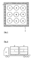
- FIG. 1 shows a not to scale sectional view through a possible embodiment of the storage device according to the invention.
- This consists of a container 2, which preferably has a fire protection insulation 3.
- a container 2 which preferably has a fire protection insulation 3.
- nine storage container 1 is arranged.
- the provision of fire protection insulation makes it possible to reduce the safety distance to a parked container - for example, at a hydrogen filling station - to a minimum.
- the nine storage containers 1 are now - according to an advantageous embodiment of the storage device according to the invention - in four sections divided.
- the term sequence "divided into four sections" is here to be understood to mean that the nine storage containers are connected to one another in terms of line in such a way that storage can take place at four different pressure levels within a container. Alternatively, fewer or more storage containers may be provided and / or fewer or more pressure levels may be realized.
- the individual sections or the affiliation of a single storage container to a section is indicated by the letters A, B, C and D.
- fire protection insulation 3 gas sensors and / or venting or ventilation for venting the container interior are possibly provided. These allow the setting up and operation of such a storage device without a protection zone must be complied with the storage device or the container 2.
- a container 2 preferably has a length of 5 m, a width of 2.5 m and a height of 2.5 m. If nine storage containers 1, which almost completely fill the interior of the container 2, are provided, such a container could absorb approximately 700 kg of hydrogen at a storage pressure of 900 bar.
- two or more storage devices or containers 2 are preferably arranged on a transport vehicle 4.
- the arranged in the containers 2 storage container 1 are shown in dashed lines.
- the individual memory devices or containers 2 are designed as so-called interchangeable containers.
- the storage devices or containers 2 have means for setting up, wherein these are preferably designed to be height-adjustable.
- the container 2 can be loaded and unloaded by the truck 4 itself, without the need for a crane would be required.
- the erection aid is therefore preferably designed such that it can be pulled on the two long sides of the container 2 so far out that the transport vehicle can drive out after lowering by means of its air suspension under the container 2 (change container principle).
- all filling and / or removal devices in the storage device according to the invention or the container 2 are present on both sides.
- the above-described subdivision of the arranged within the container 2 storage container 1 into several sections allows emptying of the storage container 1 and a filling of a vehicle to be refueled by means of a variable mit step method.
- Such methods have very low energy consumption compared to conventional refueling methods.
- the above-described memory device according to the invention is suitable not only for the transport and (intermediate) storage of compressed hydrogen but equally for any other (compressible) medium.
- FIG. 3 one is already shown on the basis of FIG. 1 explained storage device according to the invention comprising a container 2 and nine arranged in it storage container 1.
- the storage container 1 are, as already also with reference to the FIG. 1 explained, divided into four sections A to D.
- Each of the aforementioned four sections A to D can be connected via a separate line a to d with the network of the hydrogen filling station. This is preferably done by means of suitable quick couplings. 5
- the gaseous hydrogen can be stored in the storage containers 1 at a pressure of up to 900 bar.
- the refueling takes place a vehicle with hydrogen at a pressure of 700 bar and a temperature of 15 ° C. Due to the occurring during refueling process heating of the hydrogen in the storage tank of the vehicle to be refueled up to a temperature of max. 85 ° C, a permanent pressure of 875 bar in at least one of the storage container 1 and in at least one of the four sections A to D upright.
- a vehicle If a vehicle is to be refueled with hydrogen, its storage tank often has a very low internal pressure of only 50 bar. About the lines or line sections a, a ', 7, 11 and 13, the vehicle to be refueled is now connected to the three storage tanks 1 of section A. As soon as pressure equalization has been reached between section A and the vehicle tank, the system switches over to the next section B, C or D.
- the method according to the invention is therefore proposed to provide a cold storage in the form of a refrigeration cycle 14, which serves to store the cold obtained at the expansion machine 10.
- a refrigeration cycle 14 By means of this refrigeration cycle 14, the temperature of the hydrogen supplied to the vehicle tank during the refueling process can be averaged.
- the cold storage 14 thus ensures that at the outlet of the heat exchanger 12 during the entire refueling process, a hydrogen temperature of about -40 ° C can be maintained.
- shaft power and a cooling capacity of approximately 24 kJ / s are obtained by means of the expansion machine 10.
- the shaft power can in generator mode - this is a generator 17 provided - are fed back into the power grid.
- the energy obtained is used to drive the compressor 15.
- hydrogen is always removed from the section with the lowest pressure during the refueling process and compressed by means of the compressor 15 in the sections with the next higher pressure.
- the provision of only one compressor 15 considerably increases the energy efficiency of the refueling method according to the invention. Compared with a refueling process in which the hydrogen to be compressed is provided in liquid form, the refueling method according to the invention has only one tenth of the energy requirement.
- Expansion machine 10 and compressor 15 are preferably arranged on a common shaft in order to transmit the wave power obtained in the expansion machine 10 directly to the compressor 15 can. Both the expansion machine 10 and the compressor 15 are preferably provided with a freewheel valve, so that each strand can be temporarily short-circuited.
- the peak electric power is generated during the expansion operation. Since it may only be comparatively expensive to feed back into the power grid, it may be expedient to use the energy obtained to supply additional parts of the hydrogen filling station and / or to recharge the batteries of refueling fuel cell or electric vehicles.
- an additional high pressure accumulator 16 is provided. This serves as a buffer when changing a storage device unit or a container 2 and at the same time ensures that a vehicle to be refueled can be completely refueled even when the storage containers 1 of a storage device according to the invention are emptied.
Abstract
Description
Die Erfindung betrifft eine Speichervorrichtung zur Speicherung eines komprimierten Mediums, wie beispielsweise Wasserstoff.The invention relates to a storage device for storing a compressed medium, such as hydrogen.
Ferner betrifft die Erfindung ein Verfahren zum Betanken eines Fahrzeuges mit gasförmigem Wasserstoff mittels eines variablen Pilgerschrittverfahrens.Furthermore, the invention relates to a method for refueling a vehicle with gaseous hydrogen by means of a variable pilgrim step method.
Unter dem Begriff "Fahrzeug" seien nachfolgend alle Arten von Land-, Luft- und Wasser-Fahrzeugen zu verstehen, bei denen eine Betankung mit einem komprimierten Medium, insbesondere mit Wasserstoff, realisierbar ist. Unter dem Begriff "Medium" seien nachfolgend u. a. Gase und Gasgemische zu verstehen.The term "vehicle" below all types of land, air and water vehicles are to be understood, in which a refueling with a compressed medium, in particular with hydrogen, can be realized. The term "medium" below u. a. To understand gases and gas mixtures.
Die Versorgung von Verbrauchern bzw. Kunden mit komprimierten Medien, wie bspw. die Versorgung von Wasserstoff-Tankstellen mit komprimiertem, gasförmigem Wasserstoff, die Versorgung von Kunden unterschiedlichster Art mit komprimiertem, gasförmigem Stickstoff, etc. wird gegenwärtig dadurch realisiert, dass die komprimierten Medien in Druckgasflaschen, in Flüssigtanks oder mittels sog. Hochdruck-Trailer angeliefert werden. Insbesondere die Versorgung von Wasserstoff-Tankstellen mit komprimiertem, gasförmigem Wasserstoff ist vergleichsweise kostenintensiv. Die Ursache hierfür ist darin begründet, dass der Wasserstoff vor dem Transport verflüssigt, in verflüssigtem Zustand vom Verflüssiger zur Wasserstoff-Tankstelle transportiert und an der Wasserstoff-Tankstelle verdampft und anschließend verdichtet wird. Wünschenswert wäre zwar eine Wasserstoff-Erzeugung unmittelbar vor Ort, jedoch stehen hierfür noch keine in der Praxis mit vernünftigem Aufwand realisierbaren Verfahren zur Verfügung.The supply of consumers or customers with compressed media, such as the supply of hydrogen gas stations with compressed gaseous hydrogen, the supply of customers of various kinds with compressed, gaseous nitrogen, etc. is currently realized by the compressed media in Compressed gas cylinders, in liquid tanks or by means of so-called. High-pressure trailer to be delivered. In particular, the supply of hydrogen filling stations with compressed, gaseous hydrogen is relatively expensive. The reason for this is that the hydrogen is liquefied prior to transport, transported in the liquefied state from the liquefier to the hydrogen filling station and vaporized at the hydrogen filling station and then compressed. Although it would be desirable to produce hydrogen directly on site, there are still no available in practice with reasonable effort feasible method.
Der Transport des verflüssigten Wasserstoffs erfolgt üblicherweise in aufwendig isolierten Speicherbehältern, in denen jedoch aufgrund des unvermeidbaren Wärmeeinfalles aus der Umgebung Abdampfverluste in Kauf genommen werden müssen.The transport of the liquefied hydrogen is usually carried out in elaborately insulated storage tanks in which, however, due to the unavoidable incidence of heat from the environment Abdampfverluste must be taken into account.
Alternativ hierzu kann ein Transport von komprimiertem, gasförmigem Wasserstoff mittels Hochdruck-Trailer erfolgen. Dabei wird der Wasserstoff in mehreren, zylindrischen Speicherbehältern, die vorzugsweise dauerhaft auf einem Auflieger montiert sind, transportiert. Die Lagerung des Wasserstoffs in diesen Speicherbehältern erfolgt bei einem Druck zwischen 200 und 300 bar. Das Speichervolumen derartiger Hochdruck-Trailer beträgt bei den vorgenannten Drücken zwischen 3000 und 5000 Nm3. Von Nachteil bei dieser Art des Wasserstoffs-Transports ist jedoch, dass mit einem Lastwagen bzw. Trailer, der ein Gesamtgewicht von 40 Tonnen aufweist, lediglich eine Wasserstoffmenge zwischen 300 und 500 kg transportiert werden kann.Alternatively, a transport of compressed, gaseous hydrogen by means of high-pressure trailer done. The hydrogen is transported in several cylindrical storage containers, which are preferably permanently mounted on a semi-trailer. The storage of hydrogen in these storage tanks takes place at a pressure between 200 and 300 bar. The storage volume of such high-pressure trailers is at the aforementioned pressures between 3000 and 5000 Nm 3 . A disadvantage of this type of hydrogen transport, however, is that with a truck or trailer, which has a total weight of 40 tons, only a quantity of hydrogen between 300 and 500 kg can be transported.
Aufgabe der vorliegenden Erfindung ist es, eine gattungsgemäße Speichervorrichtung zur Speicherung eines komprimierten Mediums, wie beipielsweise Wasserstoff anzugeben, die die vorgenannten Probleme vermeidet. Ferner liegt der vorliegenden Erfindung die Aufgabe zugrunde, ein gattungsgemäßes Verfahren zum Betanken eines Fahrzeuges mit gasförmigem Wasserstoff mittels eines variablen Pilgerschrittverfahrens anzugeben.Object of the present invention is to provide a generic storage device for storing a compressed medium, such as hydrogen, for example, which avoids the aforementioned problems. Furthermore, the present invention has for its object to provide a generic method for refueling a vehicle with gaseous hydrogen by means of a variable pilgrim step method.
Zur Lösung dieser Aufgabe wird eine gattungsgemäße Speichervorrichtung vorgeschlagen, die dadurch gekennzeichnet ist, dass sie mehrere Speicherbehälter und einen Container, in dem die Speicherbehälter angeordnet sind, aufweist.To solve this problem, a generic storage device is proposed, which is characterized in that it comprises a plurality of storage containers and a container in which the storage containers are arranged.
Verfahrensseitig wird die gestellte Aufgabe dadurch gelöst, dass der gasförmige Wasserstoff aus einer erfindungsgemäß ausgelegten Speichervorrichtung, die wenigstens in zwei, vorzugsweise in vier oder mehr als vier Sektionen unterteilt ist, entnommen und dem zu betankenden Fahrzeug zugeführt wird.The method, the object is achieved in that the gaseous hydrogen from an inventively designed storage device, which is divided into at least two, preferably four or more than four sections, removed and fed to the vehicle to be refueled.
Weitere vorteilhafte Ausgestaltungen der erfindungsgemäßen Speichervorrichtung zur Speicherung eines komprimierten Mediums sowie des erfindungsgemäßen Verfahrens zum Betanken eines Fahrzeuges mit gasförmigem Wasserstoff mittels eines variablen Pilgerschrittverfahrens, die Gegenstände der abhängigen Patentansprüche darstellen, sind dadurch gekennzeichnet, dass
- innerhalb eines Containers wenigstens neun Speicherbehälter angeordnet sind, wobei die wenigstens neun Speicherbehälter vorzugsweise in vier Sektionen unterteilt sind - hierbei sie die Begriffsfolge "in vier Sektionen unterteilt" so zu verstehen, dass die wenigstens neun Speicherbehälter leitungsmäßig derart miteinander verbunden sind, dass innerhalb eines Containers eine Speicherung auf vier unterschiedlichen Druckniveaus erfolgen kann,
- der Container und/oder die Speicherbehälter eine Brandschutzisolierung aufweisen,
- die Speicherbehälter zumindest teilweise aus einem Kohlefasermaterial bestehen,
- die Speicherbehälter zur Aufnahme eines auf Drücke bis 1000 bar komprimierten Mediums ausgebildet sind,
- der Container wenigstens einen Gassensor und/oder Mittel zum Entlüften des Containerinnenraumes aufweist,
- der Container für den Transport auf einem Transportfahrzeug, insbesondere einem Lastwagen oder einem Eisenbahnwagon, ausgebildet ist.
- der Container Mittel zum Aufstellen, wobei diese vorzugsweise höhenverstellbar ausgebildet sind, aufweist, wobei die Aufstellhilfe vorzugsweise derart ausgeführt ist, dass sie auf den beiden Längsseiten des Containers so weit nach außen gezogen werden kann, dass das Transportfahrzeug nach einem Absenken mittels seiner Luftfederung unter dem Container herausfahren kann,
- der Container Mittel zum Erstellen einer leitenden Verbindung mit dem Potenzialausgleich seines Aufstellungsortes, beispielsweise einer Wasserstoff-Tankstelle, aufweist,
- der dem zu betankenden Fahrzeug zugeführte Wasserstoff vor der Zuführung in das zu betankende Fahrzeug entspannt wird,
- die bei der Entspannung des Wasserstoffs gewonnene Wellen- und Kälteleistung innerhalb des Betankungsverfahrens genutzt wird und
- eine Zwischenspeicherung des dem zu betankenden Fahrzeug zugeführten Wasserstoffs erfolgt.
- within a container at least nine storage containers are arranged, wherein the at least nine storage containers preferably in four sections are subdivided - in this case they understand the term sequence "divided into four sections" so that the at least nine storage containers are conductively connected to each other in such a way that can be done within a container storage at four different pressure levels,
- the container and / or the storage containers have fire protection insulation,
- the storage containers consist at least partially of a carbon fiber material,
- the storage containers are designed to receive a medium compressed to pressures of up to 1000 bar,
- the container has at least one gas sensor and / or means for venting the container interior,
- the container is designed for transport on a transport vehicle, in particular a truck or a railway wagon.
- the container means for setting up, wherein these are preferably designed to be height adjustable, wherein the positioning aid is preferably designed such that it can be pulled on the two longitudinal sides of the container so far out that the transport vehicle after lowering by means of its air suspension under the Can pull out container,
- the container comprises means for establishing a conductive connection with the equipotential bonding of its installation site, for example a hydrogen filling station,
- the hydrogen supplied to the vehicle to be refueled is released before being fed into the vehicle to be refueled,
- used in the relaxation of hydrogen wave and cooling capacity is used within the refueling process, and
- an intermediate storage of the vehicle to be refueled hydrogen is carried out.
Die erfindungsgemäße Speichervorrichtung besteht nunmehr aus einem Container, in dem mehrere Speicherbehälter angeordnet sind. Diese weisen vorzugsweise eine zylindrische Form auf. Die gegenwärtige Kohlefasertechnologie ermöglicht es nunmehr, derartige Speicherbehälter mit einem sehr geringen Gewicht zu realisieren. Aufgrund des im Vergleich zu dem bekannten Stand der Technik niedrigeren Gewichts des bzw. der Speicherbehälter erhöht sich das Gewicht des gespeicherten Wasserstoffs bei einem Fahrzeuggesamtgewicht von 40 Tonnen auf 2100 kg.The storage device according to the invention now consists of a container in which a plurality of storage containers are arranged. These preferably have a cylindrical shape. The current carbon fiber technology now makes it possible to realize such storage containers with a very low weight. Due to the lower weight of the storage container (s) compared to the known prior art, the weight of the stored hydrogen increases from a total weight of 40 tons to 2100 kg.
Ist beabsichtigt, den gasförmigen Wasserstoff für eine Betankung bei einem Druck von 700 bar und einer Temperatur von 15 °C zu nutzen, so ist es zweckmäßig, den Wasserstoff in der erfindungsgemäßen Speichervorrichtung bei einem Druck von ca. 900 bar zu speichern. Werden eine oder mehrere der erfindungsgemäßen Speichervorrichtungen auf einem Lastwagen bzw. Trailer angeordnet, so können bei diesem Druck und einem Gesamtgewicht des Lastwagens bzw. Trailers von 40 Tonnen ca. 2.100 kg Wasserstoff gespeichert und transportiert werden.If it is intended to use the gaseous hydrogen for refueling at a pressure of 700 bar and a temperature of 15 ° C, it is expedient to store the hydrogen in the storage device according to the invention at a pressure of about 900 bar. If one or more of the storage devices according to the invention are arranged on a truck or trailer, approximately 2,100 kg of hydrogen can be stored and transported at this pressure and a total weight of the truck or trailer of 40 tons.
Die erfindungsgemäße Speichervorrichtung zur Speicherung eines komprimierten Mediums, insbesondere von Wasserstoff, sowie weitere vorteilhafte Ausgestaltungen derselben seien nachfolgend anhand der in den
Die
Die neun Speicherbehälter 1 sind nunmehr - entsprechend einer vorteilhaften Ausgestaltung der erfindungsgemäßen Speichervorrichtung - in vier Sektionen unterteilt. Die Begriffsfolge "in vier Sektionen unterteilt" sei hierbei so zu verstehen, dass die neun Speicherbehälter leitungsmäßig derart miteinander verbunden sind, dass innerhalb eines Containers eine Speicherung auf vier unterschiedlichen Druckniveaus erfolgen kann. Alternativ hierzu können auch weniger oder mehr Speicherbehälter vorgesehen und/oder weniger oder mehr Druckniveaus realisiert werden. Die einzelnen Sektionen bzw. die Zugehörigkeit eines einzelnen Speicherbehälters zu einer Sektion sei durch die Buchstaben A, B, C und D gekennzeichnet.The nine
Zusätzlich zu der üblicherweise vorzusehenden Brandschutzisolierung 3 sind ggf. Gassensoren und/oder eine Entlüftungsmöglichkeit bzw. Ventilation zum Entlüften des Containerinnenraumes vorzusehen. Diese ermöglichen das Aufstellen und Betreiben einer derartigen Speichervorrichtung, ohne dass eine Schutzzone um die Speichervorrichtung bzw. den Container 2 eingehalten werden muss.In addition to the usually provided
Ein Container 2 weist vorzugsweise eine Länge von 5 m, eine Breite von 2,5 m und eine Höhe von 2,5 m auf. Werden neun Speicherbehälter 1, die den Innenraum des Containers 2 nahezu vollständig ausfüllen, vorgesehen, könnte ein derartiger Container bei einem Speicherdruck von 900 bar ca. 700 kg Wasserstoff aufnehmen.A
Wie anhand der
Die erfindungsgemäße Speichervorrichtung weiterbildend wird vorgeschlagen, dass die einzelnen Speichervorrichtungen bzw. Container 2 als sog. Wechselcontainer ausgeführt sind. Dies erfordert, dass die Speichervorrichtungen bzw. Container 2 Mittel zum Aufstellen aufweisen, wobei diese vorzugsweise höhenverstellbar ausgebildet sind. Mittels dieser Ausgestaltung können die Container 2 durch den Lastwagen 4 selbst be- und entladen werden, ohne dass hierzu ein Kran erforderlich wäre. Die Aufstellhilfe ist deshalb vorzugsweise derart ausgeführt, dass sie auf den beiden Längsseiten des Containers 2 so weit nach außen gezogen werden kann, dass das Transportfahrzeug nach einem Absenken mittels seiner Luftfederung unter dem Container 2 herausfahren kann (Wechselcontainerprinzip).Further developing the memory device according to the invention, it is proposed that the individual memory devices or
Vorteilhafterweise sind sämtliche Befüll- und/oder Entnahmeeinrichtungen bei der erfindungsgemäßen Speichervorrichtung bzw. dem Container 2 beidseitig vorhanden.Advantageously, all filling and / or removal devices in the storage device according to the invention or the
Insbesondere die vorbeschriebene Unterteilung der innerhalb des Containers 2 angeordneten Speicherbehälter 1 in mehrere Sektionen ermöglicht eine Entleerung der Speicherbehälter 1 und ein Befüllen eines zu betankenden Fahrzeuges mittels eines variablen Pilgerschrittverfahrens. Derartige Verfahren weisen, verglichen mit herkömmlichen Betankungsverfahren, einen sehr niedrigen Energieverbrauch auf.In particular, the above-described subdivision of the arranged within the
Es sei betont, dass die vorbeschriebene, erfindungsgemäße Speichervorrichtung nicht nur für den Transport sowie die (Zwischen)Speicherung von komprimiertem Wasserstoff geeignet ist, sondern gleichermaßen für jedes andere (komprimierbare) Medium.It should be emphasized that the above-described memory device according to the invention is suitable not only for the transport and (intermediate) storage of compressed hydrogen but equally for any other (compressible) medium.
Das erfindungsgemäße Verfahren zum Betanken eines Fahrzeuges mit verdichtetem, gasförmigem Wasserstoff sei nachfolgend anhand des in der
In der
Jede der vorgenannten vier Sektionen A bis D ist über eine separate Leitung a bis d mit dem Leitungsnetz der Wasserstoff-Tankstelle verbindbar. Dies geschieht vorzugsweise mittels geeigneter Schnellkupplungen 5.Each of the aforementioned four sections A to D can be connected via a separate line a to d with the network of the hydrogen filling station. This is preferably done by means of suitable quick couplings. 5
Tankstellenseitig setzen sich die vier vorgenannten Leitungen a bis d der erfindungsgemäßen Speichervorrichtung in den Leitungen a' bis d' fort. Jede dieser vier Leitungen a' bis d' teilt sich nunmehr in drei Leitungen auf, die zusammengeführt drei Hauptleitungen 7, 8 und 9 bilden. Aus offensichtlichen Gründen sind in den vorgenannten Leitungen bzw. Leitungsverzweigungen (Sperr)Ventile 6 vorzusehen.On the service station side, the four aforementioned lines a to d of the storage device according to the invention continue in the lines a 'to d'. Each of these four lines a 'to d' is now divided into three lines, which together form three
Wie bereits erwähnt, kann der gasförmige Wasserstoff in den Speicherbehältern 1 bei einem Druck bis zu 900 bar gespeichert werden. Üblicherweise erfolgt die Betankung eines Fahrzeuges mit Wasserstoff bei einem Druck von 700 bar und einer Temperatur von 15 °C. Aufgrund der während des Betankungsvorganges auftretenden Erhitzung des Wasserstoffs im Speichertank des zu betankenden Fahrzeuges bis auf eine Temperatur von max. 85 °C, ist ein permanenter Druck von 875 bar in wenigstens einem der Speicherbehälter 1 bzw. in wenigstens einer der vier Sektionen A bis D aufrecht zu halten.As already mentioned, the gaseous hydrogen can be stored in the
Soll nun ein Fahrzeug mit Wasserstoff betankt werden, weist dessen Speichertank oftmals einen sehr niedrigen Innendruck von nurmehr 50 bar auf. Über die Leitungen bzw. Leitungsabschnitte a, a', 7, 11 und 13 wird das zu betankende Fahrzeug nunmehr mit den drei Speicherbehältern 1 der Sektion A verbunden. Sobald zwischen der Sektion A und dem Fahrzeugstank ein Druckausgleich erreicht ist, wird auf die nächste Sektion B, C oder D umgeschaltet.If a vehicle is to be refueled with hydrogen, its storage tank often has a very low internal pressure of only 50 bar. About the lines or line sections a, a ', 7, 11 and 13, the vehicle to be refueled is now connected to the three
Da zu Beginn des Betankungsvorganges zwischen der Sektion A und dem Fahrzeugtank ein großer Druckunterschied besteht, kann an der Expansionsmaschine 10 vergleichsweise viel, zeitweilig sogar zu viel Kälte gewonnen werden. Das erfindungsgemäße Verfahren weiterbildend wird daher vorgeschlagen, einen Kältespeicher in Form eines Kältekreislaufes 14 vorzusehen, der der Speicherung der an der Expansionsmaschine 10 gewonnenen Kälte dient. Mittels dieses Kältekreislaufes 14 kann die Temperatur des während des Betankungsvorganges dem Fahrzeugtank zugeführten Wasserstoffs gemittelt werden. Der Kältespeicher 14 stellt damit sicher, dass am Austritt des Wärmetauschers 12 während des gesamten Betankungsvorganges eine Wasserstoff-Temperatur von ca. -40 °C eingehalten werden kann.Since there is a large difference in pressure between the section A and the vehicle tank at the beginning of the refueling process, comparatively much, at times even too much cold can be obtained at the
Bei einem durchschnittlichen Betankungsvorgang wird mittels der Expansionsmaschine 10 eine Wellenleistung sowie eine Kälteleistung von jeweils ca. 24 kJ/s gewonnen. Die Wellenleistung kann im Generatorbetrieb - hierzu ist ein Generator 17 vorgesehen - in das Energienetz zurückgespeist werden. In vorteilhafter Weise wird die gewonnene Energie jedoch für den Antrieb des Verdichters 15 genutzt.In an average refueling operation, shaft power and a cooling capacity of approximately 24 kJ / s are obtained by means of the
Der (zentrale) Verdichter 15 dient dazu, Wasserstoff, der beispielsweise aus der Sektion A entnommen und über die Leitungsabschnitte a, a' und 9 dem Verdichter 15 zugeführt wird, zu verdichten und über die Leitungsabschnitte 8, x' (wobei x' = b', c' und/oder d') und x (wobei x = b, c und/oder d) in wenigstens eine der drei anderen Sektionen B, C und/oder D zu führen. In vorteilhafter Weise wird während des Betankungsvorganges Wasserstoff immer aus der Sektion mit dem geringsten Druck entnommen und mittels des Verdichters 15 in die Sektionen mit dem nächst höheren Druck verdichtet. Das Vorsehen lediglich eines Verdichters 15 erhöht die Energieeffizienz des erfindungsgemäßen Betankungsverfahrens erheblich. Verglichen mit einem Betankungsverfahren, bei dem der zu komprimierende Wasserstoff in flüssiger Form bereitgestellt wird, weist das erfindungsgemäße Betankungsverfahren lediglich ein Zehntel des Energiebedarfes auf.The (central)
Expansionsmaschine 10 und Verdichter 15 sind vorzugsweise auf einer gemeinsamen Welle angeordnet, um die in der Expansionsmaschine 10 gewonnene Wellenleistung direkt auf den Verdichter 15 übertragen zu können. Sowohl die Expansionsmaschine 10 als auch der Verdichter 15 sind vorzugsweise mit einem Freilaufventil versehen, so dass jeder Strang zeitweise kurzgeschlossen werden kann.
Die elektrische Spitzenleistung wird während des Expansionsbetriebs erzeugt. Da sie unter Umständen nur vergleichsweise aufwendig in das Stromnetz zurückspeisbar ist, ist es ggf. zweckmäßig, die gewonnene Energie zur Versorgung weiterer Anlagenteilen der Wasserstoff-Tankstelle und/oder zum Wiederaufladen der Akkus von zu betankenden Brennstoffzellen- oder Elektro-Fahrzeugen zu nutzen.The peak electric power is generated during the expansion operation. Since it may only be comparatively expensive to feed back into the power grid, it may be expedient to use the energy obtained to supply additional parts of the hydrogen filling station and / or to recharge the batteries of refueling fuel cell or electric vehicles.
In vorteilhafter Weise ist ein zusätzlicher Hochdruckspeicher 16 vorgesehen. Dieser dient beim Wechsel einer Speichervorrichtungseinheit bzw. eines Containers 2 als Puffer und stellt gleichzeitig sicher, dass ein zu betankendes Fahrzeug auch dann vollständig betankt werden kann, wenn die Speicherbehälter 1 einer erfindungsgemäßen Speichervorrichtung entleert sind.Advantageously, an additional
Mittels des vorbeschriebenen, variablen Pilgerschrittverfahrens bzw. der vorbeschriebenen, variablen Pilgerschrittentleerung kann nun ein Betanken eines Fahrzeuges aus der erfindungsgemäßen Speichervorrichtung bzw. aus deren Speicherbehälter 1 mit einem vergleichsweise niedrigen Energieaufwand realisiert werden.By means of the above-described, variable pilgrim step method or the above-described, variable pilgrim step emptying, refueling of a vehicle from the storage device according to the invention or from its
Claims (14)
Applications Claiming Priority (1)
| Application Number | Priority Date | Filing Date | Title |
|---|---|---|---|
| DE102008034499A DE102008034499A1 (en) | 2008-07-24 | 2008-07-24 | Storage device for compressed media and method for refueling vehicles |
Publications (1)
| Publication Number | Publication Date |
|---|---|
| EP2148127A2 true EP2148127A2 (en) | 2010-01-27 |
Family
ID=40718983
Family Applications (1)
| Application Number | Title | Priority Date | Filing Date |
|---|---|---|---|
| EP09006295A Withdrawn EP2148127A2 (en) | 2008-07-24 | 2009-05-08 | Storage device for compressed media and method for filling the tank of vehicles |
Country Status (7)
| Country | Link |
|---|---|
| US (1) | US20100018603A1 (en) |
| EP (1) | EP2148127A2 (en) |
| JP (1) | JP2010032053A (en) |
| KR (1) | KR20100011932A (en) |
| CN (1) | CN101634397A (en) |
| CA (1) | CA2673156A1 (en) |
| DE (1) | DE102008034499A1 (en) |
Cited By (4)
| Publication number | Priority date | Publication date | Assignee | Title |
|---|---|---|---|---|
| WO2011018175A1 (en) * | 2009-08-11 | 2011-02-17 | Linde Aktiengesellschaft | Filling of a storage vessel with a compressed medium |
| WO2012123349A1 (en) * | 2011-03-11 | 2012-09-20 | Shell Internationale Research Maatschappij B.V. | Hydrogen dispensing process and system |
| EP2569571B1 (en) | 2010-05-12 | 2017-07-19 | Linde Aktiengesellschaft | Hydrogen infrastructure |
| EP3221634A4 (en) * | 2014-11-21 | 2018-07-25 | Washington State University Research Foundation | Hydrogen fueling systems and methods |
Families Citing this family (24)
| Publication number | Priority date | Publication date | Assignee | Title |
|---|---|---|---|---|
| DE102009019275A1 (en) | 2008-10-09 | 2010-04-15 | Linde Aktiengesellschaft | Refueling vehicles with pressurized gaseous media |
| EP2748512B1 (en) * | 2011-08-22 | 2018-12-19 | Tranzgaz Inc. | Method of fabricating type 4 cylinders and arranging in transportation housings for transport of gaseous fluids |
| JP2013148195A (en) * | 2012-01-23 | 2013-08-01 | Toshiba Corp | Hydrogen gas replenishment control system |
| JP6128874B2 (en) * | 2013-02-08 | 2017-05-17 | エア・ウォーター・プラントエンジニアリング株式会社 | Liquefied gas supply apparatus and method |
| DE102013002431A1 (en) * | 2013-02-12 | 2014-08-14 | Linde Aktiengesellschaft | Filling of storage containers with a gaseous, pressurized medium, in particular hydrogen |
| KR101537443B1 (en) * | 2013-07-24 | 2015-07-16 | 한국가스공사 | Liquefied natural gas charging stantion using lng tank container and liquefied natural gas charging method using the same |
| JP6289964B2 (en) * | 2014-03-27 | 2018-03-07 | Jxtgエネルギー株式会社 | Hydrogen station |
| WO2016140404A1 (en) * | 2015-03-03 | 2016-09-09 | 한국가스공사 | Lng tank container transport ship, and transport method using same |
| JP2016176592A (en) * | 2015-03-23 | 2016-10-06 | 株式会社日立プラントメカニクス | Hydrogen precool system |
| JP6440545B2 (en) * | 2015-03-25 | 2018-12-19 | Jxtgエネルギー株式会社 | Accumulator unit, hydrogen station, and hydrogen filling method |
| CN108700259B (en) * | 2016-02-23 | 2020-12-29 | 东奇柯系统解决方案株式会社 | Expansion turbine compressor type filling system for high-pressure hydrogen |
| JP2017150661A (en) * | 2016-02-23 | 2017-08-31 | 株式会社日立プラントメカニクス | Control method of high pressure hydrogen charging system with expansion turbine and compressor |
| JP6796505B2 (en) * | 2016-02-23 | 2020-12-09 | トキコシステムソリューションズ株式会社 | High-pressure hydrogen expansion turbine / compressor filling system |
| CN105966370B (en) * | 2016-05-11 | 2018-06-08 | 新兴能源装备股份有限公司 | A kind of integrated form aerating semitrailer |
| JP6708505B2 (en) * | 2016-07-14 | 2020-06-10 | 株式会社日立プラントメカニクス | High-pressure hydrogen expansion turbine filling system |
| DE102016214509A1 (en) * | 2016-08-05 | 2018-02-08 | Robert Bosch Gmbh | Fuel reservoir |
| US10267456B2 (en) * | 2016-09-22 | 2019-04-23 | Uchicago Argonne, Llc | Two-tier tube-trailer operation method and system to reduce hydrogen refueling cost |
| JP6231245B1 (en) * | 2017-08-24 | 2017-11-15 | 株式会社日立プラントメカニクス | High-pressure hydrogen expansion turbine filling system |
| CN108150824B (en) * | 2018-02-09 | 2024-04-05 | 中国人民解放军第四三二八工厂 | Gas cylinder group system and gas supply device comprising same |
| DE102019132546A1 (en) * | 2019-11-29 | 2021-06-02 | Deutsches Zentrum für Luft- und Raumfahrt e.V. | Energy supply system, vehicle and method for supplying energy |
| AU2021273192A1 (en) * | 2020-05-12 | 2023-02-02 | Universal Hydrogen Co. | Systems and methods for storing, transporting, and using hydrogen |
| JP7390972B2 (en) | 2020-05-18 | 2023-12-04 | Jfeコンテイナー株式会社 | Hydrogen supply system and hydrogen supply method to ships |
| DE102020207827A1 (en) | 2020-06-24 | 2021-12-30 | Argo Gmbh | Filling device for filling storage containers with compressed hydrogen, filling station having the same and method for filling a storage container |
| EP4237739A1 (en) | 2020-10-30 | 2023-09-06 | Universal Hydrogen Co. | Systems and methods for storing liquid hydrogen |
Family Cites Families (16)
| Publication number | Priority date | Publication date | Assignee | Title |
|---|---|---|---|---|
| US2761397A (en) * | 1951-12-21 | 1956-09-04 | Air Reduction | Trailer |
| US4542774A (en) * | 1982-09-09 | 1985-09-24 | Aga Ab | Delivery system and method for pressurized gas |
| US5040933A (en) * | 1990-05-08 | 1991-08-20 | Union Carbide Industrial Gases Technology Corporation | Trailer for cylindrical container modules |
| US5253682A (en) * | 1991-12-13 | 1993-10-19 | Haskett Carl E | Free piston gas delivery apparatus and method |
| JP3412176B2 (en) * | 1992-11-24 | 2003-06-03 | 株式会社タツノ・メカトロニクス | Gas filling equipment |
| US5603360A (en) * | 1995-05-30 | 1997-02-18 | Teel; James R. | Method and system for transporting natural gas from a pipeline to a compressed natural gas automotive re-fueling station |
| US5685350A (en) * | 1996-02-07 | 1997-11-11 | Air Products And Chemicals, Inc. | Method and apparatus for transporting, storing and delivering dangerous chemicals |
| US5884675A (en) * | 1997-04-24 | 1999-03-23 | Krasnov; Igor | Cascade system for fueling compressed natural gas |
| US6014995A (en) * | 1998-07-31 | 2000-01-18 | Agnew; A. Patrick | Onsite petrochemical storage and transport system |
| JP2004239362A (en) * | 2003-02-06 | 2004-08-26 | Tatsuno Corp | Mobile gas filling device |
| US6786245B1 (en) * | 2003-02-21 | 2004-09-07 | Air Products And Chemicals, Inc. | Self-contained mobile fueling station |
| JP4046624B2 (en) * | 2003-02-24 | 2008-02-13 | 東京瓦斯株式会社 | Compressed natural gas rapid filling vehicle |
| US7316859B2 (en) * | 2003-06-23 | 2008-01-08 | Praxair Technology, Inc. | Storage system and method for supplying hydrogen to a polymer membrane fuel cell |
| JP4424935B2 (en) * | 2003-07-02 | 2010-03-03 | エア・ウォーター株式会社 | Mobile hydrogen station and operation method thereof |
| JP4353002B2 (en) * | 2004-06-24 | 2009-10-28 | 株式会社タツノ・メカトロニクス | Gas filling device |
| JP2007278467A (en) * | 2006-04-11 | 2007-10-25 | Honda Motor Co Ltd | High pressure gas filling system |
-
2008
- 2008-07-24 DE DE102008034499A patent/DE102008034499A1/en not_active Withdrawn
-
2009
- 2009-05-08 EP EP09006295A patent/EP2148127A2/en not_active Withdrawn
- 2009-06-29 US US12/493,326 patent/US20100018603A1/en not_active Abandoned
- 2009-07-20 CA CA2673156A patent/CA2673156A1/en not_active Abandoned
- 2009-07-22 CN CN200910161604A patent/CN101634397A/en active Pending
- 2009-07-23 KR KR1020090067325A patent/KR20100011932A/en not_active Application Discontinuation
- 2009-07-24 JP JP2009173442A patent/JP2010032053A/en active Pending
Cited By (7)
| Publication number | Priority date | Publication date | Assignee | Title |
|---|---|---|---|---|
| WO2011018175A1 (en) * | 2009-08-11 | 2011-02-17 | Linde Aktiengesellschaft | Filling of a storage vessel with a compressed medium |
| EP2569571B1 (en) | 2010-05-12 | 2017-07-19 | Linde Aktiengesellschaft | Hydrogen infrastructure |
| WO2012123349A1 (en) * | 2011-03-11 | 2012-09-20 | Shell Internationale Research Maatschappij B.V. | Hydrogen dispensing process and system |
| US20140110017A1 (en) * | 2011-03-11 | 2014-04-24 | Nikunj Gupta | Hydrogen dispensing process and system |
| US9458968B2 (en) | 2011-03-11 | 2016-10-04 | Shell Oil Company | Hydrogen dispensing process and system |
| EP3221634A4 (en) * | 2014-11-21 | 2018-07-25 | Washington State University Research Foundation | Hydrogen fueling systems and methods |
| US10323794B2 (en) | 2014-11-21 | 2019-06-18 | Washington State University | Hydrogen fueling systems and methods |
Also Published As
| Publication number | Publication date |
|---|---|
| KR20100011932A (en) | 2010-02-03 |
| JP2010032053A (en) | 2010-02-12 |
| CN101634397A (en) | 2010-01-27 |
| US20100018603A1 (en) | 2010-01-28 |
| CA2673156A1 (en) | 2010-01-24 |
| DE102008034499A1 (en) | 2010-01-28 |
Similar Documents
| Publication | Publication Date | Title |
|---|---|---|
| EP2148127A2 (en) | Storage device for compressed media and method for filling the tank of vehicles | |
| EP1360084B1 (en) | Filling station for hydrogen | |
| DE102007011530A1 (en) | Method for filling a pressure accumulator provided for a cryogenic storage medium, in particular hydrogen | |
| DE102010044035B4 (en) | System for supplying a mobile device with a gaseous fuel | |
| EP3669113A1 (en) | Trailer comprising a high-pressure tank for transporting a gaseous and/or liquid fuel, system of trailer and traction vehicle, method for filling the high-pressure tank, and control device | |
| DE102008060127A1 (en) | Arrangement for refueling motor vehicles, has cold accumulator loaded by heat exchange with deep-frozen hydrogen, which removes large storage tank | |
| DE102007011742A1 (en) | Process to refuel pressurised automotive fuel tank with liquid hydrogen | |
| DE102017204746B4 (en) | HYDROGEN GAS STATION | |
| DE102014005290A1 (en) | Commercial vehicle with replaceable energy supply unit | |
| DE102017011032A1 (en) | Vehicle trailer | |
| DE102007023821A1 (en) | Method for filling cryogenic hydrogen tank on vehicle has residual gas tapped off to be conditioned at lower temperature before returning to cool the tank prior to filling with fresh gas | |
| EP2481969A1 (en) | Mobile compressed gas dispensing device | |
| DE102019000519A1 (en) | Transport vehicle and use of a liquid hydrogen container transported by a transport vehicle | |
| DE102018001298A1 (en) | Vehicle trailer | |
| DE202013101593U1 (en) | Device for gas supply | |
| EP1500864A2 (en) | Process for filling a vehicle tank | |
| DE102013210750A1 (en) | Device for gas supply | |
| DE102007057979A1 (en) | Cryogenic hydrogen filling method for storage container i.e. cryogenic tank, of motor vehicle, involves re-cooling hydrogen using suitable cooling potential, supplying residual gas and supplying large portion of gas into tank | |
| DE102015008563A1 (en) | Device for cooling a compressed gas container | |
| DE102010010108B4 (en) | Method of storing and storing natural gas | |
| DE102009040947A1 (en) | Container and method for storing gas | |
| WO2005003621A1 (en) | Storage system for cryogenic media | |
| DE102015221537A1 (en) | Motor vehicle with a pressure tank | |
| DE102019001868B4 (en) | Mobile system for supplying a customer with a fluid | |
| DE102017120256A1 (en) | Traction power hybrid charging arrangement |
Legal Events
| Date | Code | Title | Description |
|---|---|---|---|
| PUAI | Public reference made under article 153(3) epc to a published international application that has entered the european phase |
Free format text: ORIGINAL CODE: 0009012 |
|
| AK | Designated contracting states |
Kind code of ref document: A2 Designated state(s): AT BE BG CH CY CZ DE DK EE ES FI FR GB GR HR HU IE IS IT LI LT LU LV MC MK MT NL NO PL PT RO SE SI SK TR |
|
| AX | Request for extension of the european patent |
Extension state: AL BA RS |
|
| STAA | Information on the status of an ep patent application or granted ep patent |
Free format text: STATUS: THE APPLICATION IS DEEMED TO BE WITHDRAWN |
|
| 18D | Application deemed to be withdrawn |
Effective date: 20151201 |