EP2148071A1 - Particulate filter regenerating system - Google Patents
Particulate filter regenerating system Download PDFInfo
- Publication number
- EP2148071A1 EP2148071A1 EP09009110A EP09009110A EP2148071A1 EP 2148071 A1 EP2148071 A1 EP 2148071A1 EP 09009110 A EP09009110 A EP 09009110A EP 09009110 A EP09009110 A EP 09009110A EP 2148071 A1 EP2148071 A1 EP 2148071A1
- Authority
- EP
- European Patent Office
- Prior art keywords
- exhaust gas
- post
- regeneration process
- injection
- particulate filter
- Prior art date
- Legal status (The legal status is an assumption and is not a legal conclusion. Google has not performed a legal analysis and makes no representation as to the accuracy of the status listed.)
- Granted
Links
- 230000001172 regenerating effect Effects 0.000 title claims abstract description 25
- 239000013618 particulate matter Substances 0.000 claims abstract description 260
- 239000007924 injection Substances 0.000 claims abstract description 144
- 238000002347 injection Methods 0.000 claims abstract description 144
- 230000008929 regeneration Effects 0.000 claims abstract description 111
- 238000011069 regeneration method Methods 0.000 claims abstract description 111
- 238000000034 method Methods 0.000 claims abstract description 107
- 230000008569 process Effects 0.000 claims abstract description 99
- 239000000446 fuel Substances 0.000 claims abstract description 79
- 238000002485 combustion reaction Methods 0.000 claims abstract description 16
- 230000000977 initiatory effect Effects 0.000 claims abstract description 13
- 239000007789 gas Substances 0.000 claims description 79
- 230000009467 reduction Effects 0.000 claims description 36
- 230000008859 change Effects 0.000 claims description 22
- 238000001514 detection method Methods 0.000 claims description 15
- 230000002123 temporal effect Effects 0.000 claims description 15
- 238000011144 upstream manufacturing Methods 0.000 claims description 10
- 210000002421 cell wall Anatomy 0.000 description 82
- 239000011148 porous material Substances 0.000 description 37
- 238000007254 oxidation reaction Methods 0.000 description 22
- 230000008901 benefit Effects 0.000 description 18
- 239000003054 catalyst Substances 0.000 description 17
- 230000003647 oxidation Effects 0.000 description 16
- 238000012545 processing Methods 0.000 description 16
- 230000006866 deterioration Effects 0.000 description 9
- 238000013500 data storage Methods 0.000 description 8
- 210000004027 cell Anatomy 0.000 description 5
- 230000000694 effects Effects 0.000 description 4
- 230000006870 function Effects 0.000 description 4
- 238000010586 diagram Methods 0.000 description 3
- 239000003502 gasoline Substances 0.000 description 3
- BASFCYQUMIYNBI-UHFFFAOYSA-N platinum Substances [Pt] BASFCYQUMIYNBI-UHFFFAOYSA-N 0.000 description 3
- 239000000758 substrate Substances 0.000 description 3
- 238000004891 communication Methods 0.000 description 2
- 238000012986 modification Methods 0.000 description 2
- 230000004048 modification Effects 0.000 description 2
- 238000000746 purification Methods 0.000 description 2
- 230000004044 response Effects 0.000 description 2
- 230000003685 thermal hair damage Effects 0.000 description 2
- 239000004215 Carbon black (E152) Substances 0.000 description 1
- UGFAIRIUMAVXCW-UHFFFAOYSA-N Carbon monoxide Chemical compound [O+]#[C-] UGFAIRIUMAVXCW-UHFFFAOYSA-N 0.000 description 1
- 230000002411 adverse Effects 0.000 description 1
- PNEYBMLMFCGWSK-UHFFFAOYSA-N aluminium oxide Inorganic materials [O-2].[O-2].[O-2].[Al+3].[Al+3] PNEYBMLMFCGWSK-UHFFFAOYSA-N 0.000 description 1
- 238000013459 approach Methods 0.000 description 1
- 229910002091 carbon monoxide Inorganic materials 0.000 description 1
- 230000015556 catabolic process Effects 0.000 description 1
- 239000002131 composite material Substances 0.000 description 1
- 230000006835 compression Effects 0.000 description 1
- 238000007906 compression Methods 0.000 description 1
- 229910052878 cordierite Inorganic materials 0.000 description 1
- 238000006731 degradation reaction Methods 0.000 description 1
- JSKIRARMQDRGJZ-UHFFFAOYSA-N dimagnesium dioxido-bis[(1-oxido-3-oxo-2,4,6,8,9-pentaoxa-1,3-disila-5,7-dialuminabicyclo[3.3.1]nonan-7-yl)oxy]silane Chemical compound [Mg++].[Mg++].[O-][Si]([O-])(O[Al]1O[Al]2O[Si](=O)O[Si]([O-])(O1)O2)O[Al]1O[Al]2O[Si](=O)O[Si]([O-])(O1)O2 JSKIRARMQDRGJZ-UHFFFAOYSA-N 0.000 description 1
- 238000011156 evaluation Methods 0.000 description 1
- 239000002828 fuel tank Substances 0.000 description 1
- 229930195733 hydrocarbon Natural products 0.000 description 1
- 150000002430 hydrocarbons Chemical class 0.000 description 1
- 230000015654 memory Effects 0.000 description 1
- 239000000203 mixture Substances 0.000 description 1
- 229910000510 noble metal Inorganic materials 0.000 description 1
- 239000003921 oil Substances 0.000 description 1
- 229910052697 platinum Inorganic materials 0.000 description 1
- 238000007789 sealing Methods 0.000 description 1
- HBMJWWWQQXIZIP-UHFFFAOYSA-N silicon carbide Chemical compound [Si+]#[C-] HBMJWWWQQXIZIP-UHFFFAOYSA-N 0.000 description 1
- 229910010271 silicon carbide Inorganic materials 0.000 description 1
- 238000012360 testing method Methods 0.000 description 1
Images


Classifications
-
- F—MECHANICAL ENGINEERING; LIGHTING; HEATING; WEAPONS; BLASTING
- F02—COMBUSTION ENGINES; HOT-GAS OR COMBUSTION-PRODUCT ENGINE PLANTS
- F02D—CONTROLLING COMBUSTION ENGINES
- F02D41/00—Electrical control of supply of combustible mixture or its constituents
- F02D41/02—Circuit arrangements for generating control signals
- F02D41/021—Introducing corrections for particular conditions exterior to the engine
- F02D41/0235—Introducing corrections for particular conditions exterior to the engine in relation with the state of the exhaust gas treating apparatus
- F02D41/027—Introducing corrections for particular conditions exterior to the engine in relation with the state of the exhaust gas treating apparatus to purge or regenerate the exhaust gas treating apparatus
- F02D41/029—Introducing corrections for particular conditions exterior to the engine in relation with the state of the exhaust gas treating apparatus to purge or regenerate the exhaust gas treating apparatus the exhaust gas treating apparatus being a particulate filter
-
- B—PERFORMING OPERATIONS; TRANSPORTING
- B01—PHYSICAL OR CHEMICAL PROCESSES OR APPARATUS IN GENERAL
- B01D—SEPARATION
- B01D53/00—Separation of gases or vapours; Recovering vapours of volatile solvents from gases; Chemical or biological purification of waste gases, e.g. engine exhaust gases, smoke, fumes, flue gases, aerosols
- B01D53/34—Chemical or biological purification of waste gases
- B01D53/92—Chemical or biological purification of waste gases of engine exhaust gases
- B01D53/94—Chemical or biological purification of waste gases of engine exhaust gases by catalytic processes
- B01D53/944—Simultaneously removing carbon monoxide, hydrocarbons or carbon making use of oxidation catalysts
-
- B—PERFORMING OPERATIONS; TRANSPORTING
- B01—PHYSICAL OR CHEMICAL PROCESSES OR APPARATUS IN GENERAL
- B01D—SEPARATION
- B01D53/00—Separation of gases or vapours; Recovering vapours of volatile solvents from gases; Chemical or biological purification of waste gases, e.g. engine exhaust gases, smoke, fumes, flue gases, aerosols
- B01D53/34—Chemical or biological purification of waste gases
- B01D53/92—Chemical or biological purification of waste gases of engine exhaust gases
- B01D53/94—Chemical or biological purification of waste gases of engine exhaust gases by catalytic processes
- B01D53/9495—Controlling the catalytic process
-
- F—MECHANICAL ENGINEERING; LIGHTING; HEATING; WEAPONS; BLASTING
- F02—COMBUSTION ENGINES; HOT-GAS OR COMBUSTION-PRODUCT ENGINE PLANTS
- F02D—CONTROLLING COMBUSTION ENGINES
- F02D41/00—Electrical control of supply of combustible mixture or its constituents
- F02D41/02—Circuit arrangements for generating control signals
- F02D41/14—Introducing closed-loop corrections
- F02D41/1438—Introducing closed-loop corrections using means for determining characteristics of the combustion gases; Sensors therefor
- F02D41/1444—Introducing closed-loop corrections using means for determining characteristics of the combustion gases; Sensors therefor characterised by the characteristics of the combustion gases
- F02D41/1448—Introducing closed-loop corrections using means for determining characteristics of the combustion gases; Sensors therefor characterised by the characteristics of the combustion gases the characteristics being an exhaust gas pressure
-
- B—PERFORMING OPERATIONS; TRANSPORTING
- B01—PHYSICAL OR CHEMICAL PROCESSES OR APPARATUS IN GENERAL
- B01D—SEPARATION
- B01D2251/00—Reactants
- B01D2251/20—Reductants
- B01D2251/208—Hydrocarbons
-
- B—PERFORMING OPERATIONS; TRANSPORTING
- B01—PHYSICAL OR CHEMICAL PROCESSES OR APPARATUS IN GENERAL
- B01D—SEPARATION
- B01D2255/00—Catalysts
- B01D2255/10—Noble metals or compounds thereof
- B01D2255/102—Platinum group metals
- B01D2255/1021—Platinum
-
- B—PERFORMING OPERATIONS; TRANSPORTING
- B01—PHYSICAL OR CHEMICAL PROCESSES OR APPARATUS IN GENERAL
- B01D—SEPARATION
- B01D2255/00—Catalysts
- B01D2255/20—Metals or compounds thereof
- B01D2255/207—Transition metals
- B01D2255/20715—Zirconium
-
- B—PERFORMING OPERATIONS; TRANSPORTING
- B01—PHYSICAL OR CHEMICAL PROCESSES OR APPARATUS IN GENERAL
- B01D—SEPARATION
- B01D2255/00—Catalysts
- B01D2255/20—Metals or compounds thereof
- B01D2255/209—Other metals
- B01D2255/2092—Aluminium
-
- B—PERFORMING OPERATIONS; TRANSPORTING
- B01—PHYSICAL OR CHEMICAL PROCESSES OR APPARATUS IN GENERAL
- B01D—SEPARATION
- B01D2258/00—Sources of waste gases
- B01D2258/01—Engine exhaust gases
- B01D2258/012—Diesel engines and lean burn gasoline engines
-
- B—PERFORMING OPERATIONS; TRANSPORTING
- B01—PHYSICAL OR CHEMICAL PROCESSES OR APPARATUS IN GENERAL
- B01D—SEPARATION
- B01D2258/00—Sources of waste gases
- B01D2258/01—Engine exhaust gases
- B01D2258/014—Stoichiometric gasoline engines
-
- F—MECHANICAL ENGINEERING; LIGHTING; HEATING; WEAPONS; BLASTING
- F02—COMBUSTION ENGINES; HOT-GAS OR COMBUSTION-PRODUCT ENGINE PLANTS
- F02D—CONTROLLING COMBUSTION ENGINES
- F02D2200/00—Input parameters for engine control
- F02D2200/02—Input parameters for engine control the parameters being related to the engine
- F02D2200/08—Exhaust gas treatment apparatus parameters
- F02D2200/0812—Particle filter loading
-
- F—MECHANICAL ENGINEERING; LIGHTING; HEATING; WEAPONS; BLASTING
- F02—COMBUSTION ENGINES; HOT-GAS OR COMBUSTION-PRODUCT ENGINE PLANTS
- F02D—CONTROLLING COMBUSTION ENGINES
- F02D41/00—Electrical control of supply of combustible mixture or its constituents
- F02D41/02—Circuit arrangements for generating control signals
- F02D41/021—Introducing corrections for particular conditions exterior to the engine
- F02D41/0235—Introducing corrections for particular conditions exterior to the engine in relation with the state of the exhaust gas treating apparatus
- F02D41/024—Introducing corrections for particular conditions exterior to the engine in relation with the state of the exhaust gas treating apparatus to increase temperature of the exhaust gas treating apparatus
- F02D41/025—Introducing corrections for particular conditions exterior to the engine in relation with the state of the exhaust gas treating apparatus to increase temperature of the exhaust gas treating apparatus by changing the composition of the exhaust gas, e.g. for exothermic reaction on exhaust gas treating apparatus
-
- F—MECHANICAL ENGINEERING; LIGHTING; HEATING; WEAPONS; BLASTING
- F02—COMBUSTION ENGINES; HOT-GAS OR COMBUSTION-PRODUCT ENGINE PLANTS
- F02D—CONTROLLING COMBUSTION ENGINES
- F02D41/00—Electrical control of supply of combustible mixture or its constituents
- F02D41/02—Circuit arrangements for generating control signals
- F02D41/14—Introducing closed-loop corrections
- F02D41/1438—Introducing closed-loop corrections using means for determining characteristics of the combustion gases; Sensors therefor
- F02D41/1444—Introducing closed-loop corrections using means for determining characteristics of the combustion gases; Sensors therefor characterised by the characteristics of the combustion gases
- F02D41/1446—Introducing closed-loop corrections using means for determining characteristics of the combustion gases; Sensors therefor characterised by the characteristics of the combustion gases the characteristics being exhaust temperatures
-
- F—MECHANICAL ENGINEERING; LIGHTING; HEATING; WEAPONS; BLASTING
- F02—COMBUSTION ENGINES; HOT-GAS OR COMBUSTION-PRODUCT ENGINE PLANTS
- F02D—CONTROLLING COMBUSTION ENGINES
- F02D41/00—Electrical control of supply of combustible mixture or its constituents
- F02D41/30—Controlling fuel injection
- F02D41/38—Controlling fuel injection of the high pressure type
- F02D41/40—Controlling fuel injection of the high pressure type with means for controlling injection timing or duration
- F02D41/402—Multiple injections
- F02D41/405—Multiple injections with post injections
Definitions
- the present invention relates to a particulate filter regenerating system which comprises a fuel injection device adapted to inject fuel into a combustion chamber of an engine, and an exhaust gas temperature-adjusting device adapted, when a PM deposit amount which is an amount of particulate matter (PM) deposited in a particulate filter provided in an exhaust passage of the engine, reaches a predetermined value, to cause the fuel injection device to perform a post-injection for injecting fuel into the combustion chamber during an expansion stroke of the engine, so as to execute a filter regeneration process of raising a temperature of exhaust gas flowing into the particulate filter to bum the deposited PM.
- a fuel injection device adapted to inject fuel into a combustion chamber of an engine
- an exhaust gas temperature-adjusting device adapted, when a PM deposit amount which is an amount of particulate matter (PM) deposited in a particulate filter provided in an exhaust passage of the engine, reaches a predetermined value, to cause the fuel injection device to perform a post-injection for injecting fuel into the combustion chamber during an
- particulate (particulate matter: PM) consisting primarily of carbonaceous components is contained in exhaust gas at higher levels as compared with a normal gasoline engine configured to perform combustion of an air-fuel mixture around a stoichiometric air/fuel ratio.
- PM particulate matter
- the filter regeneration process is achieved by performing a so-called post-injection for injecting fuel into a combustion chamber during an expansion stroke of the engine. More specifically, through the post-injection, fuel components are added into exhaust gas, and burned in an oxidation catalyst or the like arranged upstream of the particulate filter, so that exhaust gas raised to high temperature flows into the particulate filter, and thereby the deposited PM is burned and removed based on functions of the high-temperature exhaust gas and a catalyst supported on the particulate filter.
- an exhaust gas purification system for an engine employing the above filter regeneration technique there has been known one type as disclosed, for example, in JP 2004-162633A .
- an exhaust gas purification system disclosed in this patent document is configured as follows. When it is determined that a difference between respective pressures detected by upstream and downstream pressure sensors provided across a particulate filter is equal to or greater than a predetermined value (i.e., the particulate filter is clogged), a post-injection (after-injection) is performed in an earlier-stage regeneration mode.
- a post-injection mode is shifted from the earlier-stage regeneration mode to a later-stage regeneration mode.
- a fuel injection amount for the post-injection (post-injection amount) is reduced, or a fuel injection timing during the post-injection (post-injection timing) is advanced, as compared with that in the earlier-stage regeneration mode, to suppress a rise in exhaust gas temperature.
- the present invention provides a particulate filter regenerating system which comprises a fuel injection device adapted to inject fuel into a combustion chamber of an engine, and an exhaust gas temperature-adjusting device adapted, when a PM deposit amount which is an amount of particulate matter (PM) deposited in a particulate filter provided in an exhaust passage of the engine, reaches a predetermined value, to cause the fuel injection device to perform a post-injection for injecting fuel into the combustion chamber during an expansion stroke of the engine, so as to execute a filter regeneration process of raising a temperature of exhaust gas flowing into the particulate filter to bum the deposited PM.
- a fuel injection device adapted to inject fuel into a combustion chamber of an engine
- an exhaust gas temperature-adjusting device adapted, when a PM deposit amount which is an amount of particulate matter (PM) deposited in a particulate filter provided in an exhaust passage of the engine, reaches a predetermined value, to cause the fuel injection device to perform a post-injection for injecting fuel into the combustion chamber during an expansion stroke
- the exhaust gas temperature-adjusting device is operable to cause the fuel injection device to stop performing the post-injection in a stage where a PM burning amount which is an amount of PM burned through the filter regeneration process is less than an initial PM deposit amount which is the PM deposit amount at a timing of initiation of the filter regeneration process, by a predetermined amount.
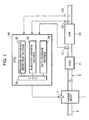
- FIG 1 is a schematic diagram showing a general configuration of an engine employing a particulate filter regenerating system according to one embodiment of the present invention.
- the engine illustrated in FIG. 1 comprises an engine body 1 having a piston and a cylinder, an intake passage 3 for supplying combustion air to the engine body 1 therethrough, and an exhaust passage 5 serving as a passage for exhaust gas discharged from the engine body 1.
- the engine body 1 is provided with an injector 7 (which corresponds to a fuel injection device set forth in the appended claims) adapted to inject fuel supplied from a fuel tank (not shown), directly into a combustion chamber of the engine body 1.
- an injector 7 which corresponds to a fuel injection device set forth in the appended claims
- This embodiment will be described on an assumption that the engine is a diesel engine, and thereby the injector 7 is adapted to inject light oil as fuel therefrom.
- a diesel oxidation catalyst (oxidation catalyst) 11 and a diesel particulate filter (particulate filter) 13 are interposed in the exhaust passage 5, in this order from an upstream side in a flow direction of exhaust gas.
- the diesel oxidation catalyst 11 will be referred to as "DOC 11 "
- the diesel particulate filter 13 will be referred to as "DPF 13”.
- the exhaust passage 5 has a first pressure sensor 21 which is provided between the DPF 13 and the DOC 11 located upstream of the DPF 13, and adapted to detect a pressure of exhaust gas flowing on an upstream side of the DPF 13, and a second pressure sensor 22 which is provided downstream of the DPF 13, and adapted to detect a pressure of exhaust gas after passing through the DPF 13.
- the DOC 11 is a type in which an oxidation catalyst is supported on a surface of a substrate composed, for example, of a honeycomb structural body made of cordierite and formed to have a large number of cells extending along an exhaust gas flow.
- the DOC 11 has a function of purifying HC (hydrocarbon) and CO (carbon monoxide) by an oxidation reaction.
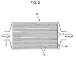
- the DPF 13 comprises a substrate composed of a honeycomb structural body made of silicon carbide and formed to have a large number of cells 17 defined by a porous cell wall 15 in such a manner as to extend along the exhaust gas flow, wherein an after-mentioned PM oxidation catalyst is supported on the cell wall 15 of the substrate 14.
- the cells 17 have a group of inlets and a group of outlets, which are alternately sealed by respective ones of a large number of sealing members (not shown).
- the DPF 13 configured as above has a function of purifying HC and CO while trapping particulate matter (hereinafter abbreviated as "PM") contained in exhaust gas.
- PM trapping particulate matter
- FIG. 3 is a sectional view enlargedly showing the cell wall 15 of the DPF 13.
- the cell wall 15 is made of a porous material having a large number of pores 15a, wherein a wall surface defining the pores 15a and an outer surface 15b of the cell wall 15 are coated with (supports) a PM oxidation catalyst layer 16 which is a layer of a PM oxidation catalyst comprising an oxide, such as alumina or Zr-based composite oxide, and a noble metal, such as Pt (platinum), loaded on the oxide.
- the pores 15a of the cell wall 15 will be referred to as "cell-wall pores 15a"
- the outer surface 15b of the cell wall 15 will be referred to as "cell-wall outer surface 15b”.
- Exhaust gas after flowing in each of the cells 17 of the DPF 15 passes through the cell-wall pores 15a in such a manner as to be distributed to two or more of the remaining cells 17. Through the distribution of exhaust gas, PM contained in the exhaust gas is trapped within the cell-wall pores 15a and on the cell-wall outer surface 15b.
- the engine is provided with an electronic control unit (ECU) 30 which is made up of conventionally well-known components, such as a central processing unit (CPU) and various memories to generally control an operation of the engine.
- the ECU 30 is adapted to receive state quantities detected by various sensors, such as the first and second pressure sensors 21, 22, an airflow sensor, and a throttle opening angle sensor, in the form of an electric signal, and execute various control operations, such as an operation of controlling an amount of fuel to be injected from the injector 7, based on various control information obtained from the received signals.
- the ECU 30 has, as primary functional elements, a pressure-difference detection section 32, an injector control section 33, a data storage section 34, and an input/output controller (IOC) 35.
- IOC input/output controller
- the pressure-difference detection section 32 is designed to calculate a difference between respective pressure detection values from the first and second pressure sensors 21, 22 to detect a difference between respective pressures of exhaust gases flowing on the upstream side and on the downstream side of the DPF 13.
- DPF pressure difference a difference between respective exhaust gas pressures on the upstream and downstream sides of (i.e., before and after) the DPF 13 will be referred to as "DPF pressure difference” or "pressure difference across the DPF 13".
- the injector control section 33 is designed to control an amount of fuel to be injected from the injector 7 (fuel injection amount) and a timing of the fuel injection (fuel injection timing). Particularly, in this embodiment, the injector control section 33 is adapted, when a DPF pressure difference detected by the pressure-difference detection section 32 reaches a predetermined value, to cause the injector 7 to perform a so-called post-injection for injecting fuel during an expansion stroke of the engine, in addition to execution of a normal fuel injection control for causing the injector 7 to inject fuel at a timing around a top dead center (TDC) of a compression stroke of the engine.
- TDC top dead center
- the post-injection is performed to raise an exhaust gas temperature to burn PM accumulated or deposited in the DPF 13. More specifically, when the DPF pressure difference reaches the predetermined value, and it is determined that the DPF 13 is getting clogged, the post-injection is performed to bum and remove PM deposited in the DPF 13 so as to regenerate the DPF 13.
- exhaust gas contains an increased amount of unburned fuel components, and the unburned fuel components undergo an oxidation reaction in the DOC (diesel oxidation catalyst) 11 in the exhaust passage 5, so that exhaust gas is raised to a high temperature. Then, based on functions of the resulting high-temperature exhaust gas and the PM oxidation catalyst layer 16 of the DPF 13, PM deposited in the DPF 13 is subjected to an oxidation reaction (burned), and removed (eliminated).
- DOC diesel oxidation catalyst
- an exhaust gas temperature-adjusting device set forth in the appended claims is made up of the injector control section 33 which is adapted, when an pressure difference across the DPF 13 reaches a predetermined value, to cause the injector 7 to perform the post-injection so as to raise an exhaust gas temperature to bum PM deposited in the DPF 13.
- the data storage section 34 stores therein threshold-value data for allowing the injector control section 33 to determine a timing of initiating or stopping the post-injection, and other data.
- the timing of initiating or stopping the post-injection is determined based on a DPF pressure difference detected by the pressure-difference detection section 32, as described in detail later.
- the data storage section 34 stores therein threshold-value data for determination on whether a value or a reduction rate of the DPF pressure difference reaches a threshold value at which the post-injection is to be initiated or stopped, and other data.
- the threshold value varies depending on an operating condition of the engine.
- the threshold-value data is stored in the data storage section 34 in the form of map data prepared on an operating condition-by-operating condition basis.
- the IOC 35 is designed to control data transmitting/receiving (data communication) between respective ones of the pressure-difference detection section 32, the injector control section 33 and the data storage section 34, and data communication between each of the sections 32 to 34 and each of the pressure sensors 21, 22 and the injector 7.
- FIG. 4 is a graph showing a change in each of a DPF pressure difference and a PM deposit amount, during a course where PM is deposited in the DPF 13, and the deposited PM is burned and removed by means of the post-injection.
- FIG. 5 is a graph showing a temporal change in state of the above DPF 13.
- the point a in FIGS. 4 and 5 indicates an initial state when no PM is deposited in the DPF 13.
- PM contained in the exhaust gas is gradually deposited in the DPF 13, and consequently a pressure difference across the DPF 13 (DPF pressure difference) is gradually increased (see the stage from the point a to the point b).
- an amount of the deposited PM (PM deposit amount) reaches a predetermined value X, and the DPF 13 is placed in a state indicated by the point b, the post-injection is initiated in response to a determination that it is necessary to bum and remove the deposited PM.
- the PM deposited in the DPF will be gradually burned and removed.
- PM deposited within the cell-wall pores 15a illustrated in FIG. 3 is primarily burned, whereas PM deposited on the cell-wall outer surface 15b is relatively hard to be burned.
- the reason is that, comparing between the cell-wall outer surface 15b and the cell-wall pores 15a, the latter has an overwhelmingly larger surface area, and a larger support amount of the PM oxidation catalyst layer 16, i.e., the latter has a larger contact area between the deposited PM and the oxidation catalyst.
- the stage from the point b to the point c in FIGS. 4 and 5 represents a step of primarily burning and removing the PM within the cell-wall pores 15a in the above manner.
- the stage from the point c to the point d in FIG. 4 represents a step of simultaneously burning and removing a small amount of PM remaining within the cell-wall pores 15a and a part of the PM deposited on the cell-wall outer surface 15b.
- the PM on the cell-wall outer surface 15b which is relatively hard to promote an oxidation reaction, is partly burned.
- a change in the DPF pressure difference during the stage c ⁇ d becomes moderate as compared with that during the stage b ⁇ c where the PM within the cell-wall pores 15a is primarily burned.
- the point d in FIGS. 4 and 5 indicates a state after the entire PM deposited within the cell-wall pores 15a is basically burned and removed. In this state, almost all the PM deposited in the DPF 13 exists on the cell-wall outer surface 15b. It is understood that, if the post-injection is continued from this state, PM remaining on the cell-wall outer surface 15b can be completely burned and removed during the stage from the point d to the point a, as indicated by the dashed line. However, in this embodiment, the post-injection is stopped at a timing corresponding to the point d.
- the reason for stopping the post-injection at the timing corresponding to the point d is that the PM on the cell-wall outer surface 15b where the DPF 13 is relatively hard to effectively bring out a burning performance thereof is left so as to suppress an increase in fuel consumption due to the post-injection, while maintaining a required performance of the DPF 13.
- a change in the PM deposit amount in the case of burning and removing the entire deposited PM including the PM on the cell-wall outer surface 15b is represented by the dashed line.
- a time T2 of the stage d ⁇ a for burning of the PM on the cell-wall outer surface 15b becomes greater than a time T1 of the stages b ⁇ c ⁇ d for burning of the PM within the cell-wall pores 15a, because the PM on the cell-wall outer surface 15b is relatively hard to be burned, as mentioned above.
- the post-injection is stopped in the state when the PM on the cell-wall outer surface 15b still remains, so as to suppress a fuel injection amount required for the post-injection, while maintaining a required performance of the DPF 13.
- the filter regeneration process is executed in such a manner that the state of the DPF 13 is cycled in order of point b ⁇ point c ⁇ point d ⁇ point b.
- a polygonal line on a rightmost side of FIG. 5 represents a change in the PM deposit amount during execution of the above process.
- the post-injection is continued until the point a where the PM deposit amount becomes approximately zero, i.e., until the entire deposited PM including PM remaining on the cell-wall outer surface 15b is substantially completely burned and removed.
- complete filter regeneration process the above process of substantially completely burning the entire PM deposited in the DPF 13 will be referred to as "complete filter regeneration process”.
- the process of burning primarily only the PM deposited within the cell-wall pores 15a by interrupting the post-injection in the state when a part of the deposited PM still remains will be referred to as "normal filter regeneration process”.
- a fuel injection amount for the post-injection is increased as compared with that in the normal filter regeneration process configured to interrupt the post-injection in the state when a part of the deposited PM still remains.
- an amount of unburned fuel components in exhaust gas is increased, so that an oxidation reaction of the unburned fuel components is positively promoted to raise an exhaust gas temperature to a higher value, and thereby a PM burning rate is increased.
- a time T1' + T2' required for completely burning the PM through the complete filter regeneration process is reduced as compared with a time T1 +T2 required for completely burning the PM through the normal filter regeneration process.
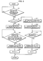
- the injector control section 33 Upon starting of a processing routine illustrated in the flowchart, the injector control section 33 first executes a processing of determining whether an amount of PM deposited in the DPF 13 (PM deposit amount) is less than the predetermined threshold value X (Step S1).
- the determination on whether the PM deposit amount is less than the predetermined threshold value X is performed by acquiring a pressure difference across the DPF 13 (DPF pressure difference) from the pressure-difference detection section 32, and checking a level of a value of the acquired DPF pressure difference.
- the determination on whether the PM deposit amount is less than the predetermined threshold value X can be made by determining whether the DPF pressure difference to be increased in proportion to the PM deposit amount is less than a predetermined threshold value (e.g., X') corresponding to the predetermined threshold value X.
- Step S1 is performed by acquiring the DPF pressure difference from the pressure-difference detection section 32 while acquiring state quantities (engine speed, engine load, etc.) indicative of a current operating condition, from various sensors, and comparing a value of the acquired DPF pressure difference with threshold-value data (i.e., data about the threshold value X') stored in the data storage section 34 in the form of a map classified on an operating condition-by-operating condition basis.
- state quantities engine speed, engine load, etc.
- a value of the acquired DPF pressure difference i.e., data about the threshold value X'
- Step S2 determines whether the number N of executions of the filter regeneration process (process of burning deposited PM by means of the post-injection) to be executed in after-mentioned Step S3 is less than a predetermined plural number Nt (e.g., about ten to several dozen) (Step S2).
- Step S2 determines whether the number N of executions of the filter regeneration process is less than the threshold value Nt. If the determination in Step S2 is YES, i.e., it is determined that the number N of executions of the filter regeneration process is less than the threshold value Nt, the injector control section 33 causes the injector 7 to perform the post-injection for injecting fuel during the expansion stroke of the engine, so as to initiate the filter regeneration process of raising a temperature of exhaust gas flowing into the DPF 13 to bum the PM deposited in the DPF 13 (Step S3).
- the injector control section 33 executes a processing of determining whether a reduction rate of the PM deposit amount in a course where the deposited PM is burned through the filter regeneration process, is less than a predetermined threshold value ⁇ , so as to determine whether the filter regeneration process should be stopped (Step S4).
- This determination processing is intended to determine whether the DPF 13 is placed in a state corresponding to the point d illustrated in FIGS. 4 and 5 , i.e., whether PM deposited within the cell-wall pores 15a (see FIG. 3 ) is substantially completely burned.
- the injector control section 33 determines that the DPF 13 is placed in the state corresponding to the point d where the filter regeneration process should be stopped.
- the threshold value ⁇ is set to a reduction rate having a gradient which is approximate intermediate between respective gradients in the stage c ⁇ d and the stage d ⁇ a.
- the above determination on whether the reduction rate of the PM deposit amount becomes less than the threshold value ⁇ can be made by acquiring the DPF pressure difference from the pressure-difference detection section 32, and checking a temporal change in the acquired DPF pressure difference. Specifically, a timing at which a reduction rate (temporal change rate) of the DPF pressure difference to be changed in response to a change in the PM deposit amount becomes less than a predetermined threshold value (e.g., ⁇ ') corresponding to the threshold value ⁇ , may be identified and set as a timing at which the reduction rate of the PM deposit amount becomes less than the threshold value ⁇ .
- a predetermined threshold value e.g., ⁇ '
- Step S4 the above determination in Step S4 is performed by acquiring the DPF pressure difference from the pressure-difference detection section 32 while acquiring state quantities indicative of a current operating state from various sensors, calculating the reduction rate (temporal change rate) of the acquired DPF pressure difference, and comparing the calculated value of the reduction rate with threshold-value data (i.e., data about the threshold value ⁇ ') stored in the data storage section 34 in the form of a map classified on an operating condition-by-operating condition basis.
- threshold-value data i.e., data about the threshold value ⁇ '
- Step S4 determines whether the reduction rate of the PM deposit amount is less than the threshold value ⁇ , or the PM within the cell-wall pores 15a is substantially completely burned. If the determination in Step S4 is YES, i.e., it is determined that the reduction rate of the PM deposit amount is less than the threshold value ⁇ , or the PM within the cell-wall pores 15a is substantially completely burned, the injector control section 33 executes a processing of causing the injector 7 to stop performing the post-injection so as to terminate the filter regeneration process (Step S5). Then, after the injector control section 33 executes a processing of incrementing the number N of executions of the filter regeneration process by one (Step S6), the routine returns to Step S1.
- Step S12 A control operation to be performed when the determination in Step S2 is NO, i.e., the number N of executions of the filter regeneration process reaches the threshold value Nt, will be described below.
- the routine shifts to Step S11, and the injector control section 33 executes a processing of setting an amount of fuel to be injected from the injector 7 during the filter regeneration process (post-injection amount), at a value which is greater than that during the normal filter regeneration process to be executed at Steps S3 to S5, by a predetermined amount. Then, the injector control section 33 controls the injector 7 to initiate the post-injection under a condition that the post-injection amount is set at the increased value, so as to bum and remove the PM deposited in the DPF 13 (Step S12).
- an exhaust gas temperature is further raised as compared with the normal filter regeneration process to be executed at Steps S3 to S5, and thereby the PM deposited in the DPF 13 is burned and removed at a relatively high PM burning rate.
- the injector control section 33 executes a processing of determining whether an amount of PM burned through the filter regeneration process (PM burning amount) becomes approximately equal to the PM deposit amount at a timing of initiation of the filter regeneration process (initial PM deposit amount) (Step S13).
- the determination in Step S13 is performed by adding a given error to a value of the DPF pressure difference in a state when the PM deposit amount is zero, to obtain a target DPF pressure difference, and determining whether the DPF pressure difference input from the pressure-difference detection section 32 becomes equal to or less than the target DPF pressure difference.
- the target DPF pressure is stored the data storage section 34 in the form of a map classified on an operating condition-by-operating condition basis.
- Step S13 determines whether the PM deposited in the DPF 13 is substantially completely burned and removed. If the determination in Step S13 is YES, i.e., it is determined that the PM deposited in the DPF 13 is substantially completely burned and removed, the injector control section 33 executes a processing of causing the injector 7 to stop performing the post-injection so as to terminate the filter regeneration process (Step S14). As above, in Steps S12 to S14, the injector control section 33 executes the complete filter regeneration process of causing the fuel injector 7 to continuously perform the post-injection until the PM burning amount becomes approximately equal to the initial PM deposit amount X, so as to substantially completely bum and remove the PM deposited in the DPF 13. Then, after termination of the complete filter regeneration process, the number N of executions of the filter regeneration process is reset to "0" (Step S15). Then, the routine returns to Step S1.
- the particulate filter regenerating system comprises an injector 7 (fuel injection device) adapted to inject fuel into a combustion chamber of an engine body 1, and an injector control section 33 (exhaust gas temperature-adjusting device) adapted, when a PM deposit amount, i.e., an amount of PM deposited in a DPF 13 (particulate filter) provided in an exhaust passage 5 of an engine, reaches a predetermined value X, to cause the injector 7 to perform a post-injection for injecting fuel into the combustion chamber during an expansion stroke of the engine, so as to execute a filter regeneration process of raising a temperature of exhaust gas flowing into the DPF 13 to bum the deposited PM.
- a PM deposit amount i.e., an amount of PM deposited in a DPF 13 (particulate filter) provided in an exhaust passage 5 of an engine
- the injector control section 33 is operable to cause the injector 7 to stop performing the post-injection in a stage where a PM burning amount, i.e., an amount of PM burned through the filter regeneration process, is less than an initial PM deposit amount, i.e., the PM deposit amount X at a timing of initiation of the filter regeneration process, by a predetermined amount (in the above embodiment, the post-injection is stopped at a timing corresponding to the point d in FIGS. 4 and 5 ).
- This particulate filter regenerating system has an advantage of being able to adequately bum and remove the PM deposited in the DPF 13, by means of the post-injection, while effectively suppressing a fuel consumption due to the post-injection.
- the post-injection is interrupted before the PM deposited in the DPF 13 is completely burned.
- This technique of stopping the post-injection intentionally in the state when the PM on the cell-wall outer surface 15b still remains provides an advantage of being able to efficiently burn and remove the deposited PM while adequately ensuring a PM burning effect based on the post-injection, and further reduce a time required for the post-injection to effectively suppress a post-injection amount (fuel consumption), differently, for example, from a technique of causing the injector 7 to continuously perform the post-injection for a longer period of time to completely bum the PM on the cell-wall outer surface 15b.
- the injector control section 33 is operable, when a reduction rate of the PM deposit amount during a course of burning of the deposited PM through the filter regeneration process becomes less than a predetermined value (threshold value ⁇ ), to cause the injector 7 to stop performing the post-injection.
- a timing at which the PM within the cell-wall pores 15a in the PM deposited in the DPF 13 is substantially completely burned and removed (a timing corresponding to the point d in FIGS. 4 and 5 ) can be adequately found out to stop the post-injection at this timing.
- This provides an advantage of being able to effectively prevent deterioration in fuel economy performance due to excessive fuel consumption for burning and removing the PM remaining on the cell-wall outer surface 15b, while efficiently burning and removing the PM within the cell-wall pores 15a which is relatively easy to be burned, to adequately regenerate the DPF 13.
- the injector control section 33 is operable to check a pressure difference across the DPF 13 (DPF pressure difference), based on detection values of pressure sensors 21, 22 adapted to detect respective pressures of exhaust gases flowing on an upstream side and on a downstream side of the DPF 13, and identify a timing at which the reduction rate of the PM deposit amount becomes less than the predetermined value (threshold value ⁇ ), based on a temporal change in the DPF pressure difference.
- DPF pressure difference pressure difference across the DPF 13
- the injector control section 33 is operable to check a pressure difference across the DPF 13 (DPF pressure difference), based on detection values of pressure sensors 21, 22 adapted to detect respective pressures of exhaust gases flowing on an upstream side and on a downstream side of the DPF 13, and identify a timing at which the reduction rate of the PM deposit amount becomes less than the predetermined value (threshold value ⁇ ), based on a temporal change in the DPF pressure difference.
- the injector control section 33 of the above embodiment is operable, in the next filter regeneration process after a normal filter regeneration process (processings in Steps S3 to S5) configured to interrupt the post-injection in the stage where the PM burning amount is less than the initial PM deposit amount by the predetermined amount, is repeated predetermined plural times (Nt times), to execute a complete filter regeneration process (processings in Steps S12 to S14) of causing the injector 7 to continuously perform the post-injection until the PM burning amount becomes approximately equal to the initial PM deposit amount.
- a normal filter regeneration process processings in Steps S3 to S5
- Nt times predetermined plural times
- This provides an advantage of being able to effectively prevent an excessive increase in PM left and deposited on the cell-wall outer surface 15b without being burned in each filter regeneration process, so as to avoid deterioration in regeneration efficiency of the DPF 13 to adequately maintain a required performance of the DPF 13 over a long period of time.
- the injector control section 33 is operable, upon execution of the complete filter regeneration process, to increase a post-injection amount from the injector 7 in such a manner that a temperature of exhaust gas flowing into the DPF 13 becomes greater than that during the normal filter regeneration process.
- This provides an advantage of being able to effectively reduce a time required for regeneration of the DPF 13 even in the complete filter regeneration process of substantially completely burning the entire PM deposited in the DPF 13.
- the exhaust gas temperature is set at a relatively low value. This provides an advantage of being able to effectively protect the DPF 13 from thermal damage or the like to enhance durability of the DPF 13.
- the injector control section 33 is operable, in the next filter regeneration process after the normal filter regeneration process (processings in Steps S3 to S5) is repeated the predetermined plural times (Nt times), to execute the complete filter regeneration process (processings in Steps S12 to S14) of causing the injector 7 to continuously perform the post-injection until the PM burning amount becomes approximately equal to the initial PM deposit amount, so as to prevent deterioration in regeneration efficiency of the DPF 13 due to an excessive increase in PM left and deposited during the normal filter regeneration process, as mentioned above.
- the following configuration may be employed.
- the injector control section 33 may be configured execute the complete filter regeneration process when the reduction rate of the PM deposit amount in the earlier stage of the filter regeneration process becomes less than a predetermined value.
- This provides an advantage of being able to adequately detect a deterioration in regeneration efficiency due to repetition of the normal filter regeneration process, based on a temporal change in the reduction rate of the PM deposit amount, and completely bum the PM deposited in the DPF 13 at the detected timing so as to effectively maintain the required performance of the DPF 13.
- the injector control section 33 is operable, during the normal filter regeneration process, to check the DPF pressure difference based on detection values of the pressure sensors 21, 22, and identify a timing at which the reduction rate of the PM deposit amount becomes less than the predetermined value (threshold value ⁇ ), based on a temporal change in the DPF pressure difference, to stop the post-injection at the identified timing, as mentioned above.
- the timing of stopping the post-injection may be identified in a different manner.
- a temperature sensor 23 may be provided on the downstream side of the DPF 13 to identify the timing of stopping the post-injection, based on a temporal change in exhaust gas temperature detected by the temperature sensor 23.
- the downstream-side exhaust gas temperature which is increased in proportion to the PM deposit amount (in other words, reduced along with a reduction in the PM deposit amount) can be checked to adequately find out a timing at which the reduction rate of the PM deposit amount becomes less than the predetermined value (e.g., a timing corresponding to the point d in FIGS. 4 and 5 ), based on a reduction rate (temporal change rate) of the downstream-side exhaust gas temperature, whereafter the post-injection can be stopped at the timing.
- the predetermined value e.g., a timing corresponding to the point d in FIGS. 4 and 5
- the injector control section 33 is operable to determine whether the reduction rate of the PM deposit amount becomes less than the threshold value ⁇ , so as to identify a timing corresponding to the point d in FIGS. 4 and 5 , i.e., a timing at which the PM within the cell-wall pores 15a in the PM deposited in the DPF 13 is substantially completely burned and removed, and stop the post-injection at this timing, as mentioned above.
- the threshold value ⁇ may be set at a different value in such a manner as to allow the injector control section 33 to identify a timing corresponding to the point c in FIGS.
- the reduction rate of the PM deposit amount at the point c i.e., a gradient in the stage c ⁇ d
- the reduction rate of the PM deposit amount at the point c does not have sufficiently large difference from that in the stage b ⁇ c where only PM within the cell-wall pores 15a is burned.
- the above approach is likely to have difficulty in identifying a timing corresponding to the point c with stable accuracy.
- the technique of identifying the timing corresponding to the point d at which the PM within the cell-wall pores 15a is substantially completely burned and stopping the post-injection at this timing is preferable in terms of an ability to determine the timing of stopping the post-injection, with stable accuracy.
- the present invention provides a particulate filter regenerating system which comprises a fuel injection device adapted to inject fuel into a combustion chamber of an engine, and an exhaust gas temperature-adjusting device adapted, when a PM deposit amount which is an amount of particulate matter (PM) deposited in a particulate filter provided in an exhaust passage of the engine, reaches a predetermined value, to cause the fuel injection device to perform a post-injection for injecting fuel into the combustion chamber during an expansion stroke of the engine, so as to execute a filter regeneration process of raising a temperature of exhaust gas flowing into the particulate filter to bum the deposited PM, wherein the exhaust gas temperature-adjusting device is operable to cause the fuel injection device to stop performing the post-injection in a stage where a PM burning amount which is an amount of PM burned through the filter regeneration process, is less than an initial PM deposit amount which is the PM deposit amount at a timing of initiation of the filter regeneration process, by a predetermined amount.
- a PM deposit amount which is an amount of particulate matter (PM)
- the post-injection is interrupted before the PM deposited in the particulate filter is completely burned.
- This technique of stopping the post-injection in the state when the PM on the cell-wall outer surface still remains provides an advantage of being able to efficiently bum and remove the deposited PM while adequately ensuring a PM burning effect based on the post-injection, and further reduce a time required for the post-injection to effectively suppress a post-injection amount (fuel consumption), differently, for example, from a technique of causing the fuel injection device to continuously perform the post-injection for a longer period of time to completely bum the PM on the cell-wall outer surface.
- the exhaust gas temperature-adjusting device is operable, when a reduction rate of the PM deposit amount during a course of burning of the deposited PM through the filter regeneration process becomes less than a predetermined value, to cause the fuel injection device to stop performing the post-injection.
- a timing at which a part of PM accumulated in the particulate filter, e.g., the PM within the cell-wall pores, is substantially completely burned and removed can be adequately found out to stop the post-injection at this timing.
- the particulate filter regenerating system comprises a pressure sensor adapted to detect respective pressures of exhaust gases flowing on an upstream side and on a downstream side of the particulate filter
- the exhaust gas temperature-adjusting device is operable to check a pressure difference across the particulate filter, based on detection values of the pressure sensor, and identify a timing at which the reduction rate of the PM deposit amount becomes less than the predetermined value, based on a temporal change in the pressure difference across the particulate filter.
- This feature provides an advantage of being able to adequately set a timing of stopping the post-injection, using a relatively simple scheme of checking only the pressure difference across the particulate filter to be reduced along with a reduction in the PM deposit amount.
- the particulate filter regenerating system comprises a temperature sensor adapted to detect a temperature of exhaust gas flowing on a downstream side of the particulate filter
- the exhaust gas temperature-adjusting device is operable to identify a timing at which the reduction rate of the PM deposit amount becomes less than the predetermined value, based on a temporal change in exhaust gas temperature detected by the temperature sensor.
- This feature also provides an advantage of being able to adequately set a timing of stopping the post-injection, using a relatively simple scheme of checking only the exhaust gas temperature on the downstream side of the particulate filter to be reduced along with a reduction in the PM deposit amount.
- the exhaust gas temperature-adjusting device is operable, in the next filter regeneration process after a normal filter regeneration process configured to interrupt the post-injection in the stage where the PM burning amount is less than the initial PM deposit amount by the predetermined amount, is repeated plural times, to execute a complete filter regeneration process of causing the fuel injection device to continuously perform the post-injection until the PM burning amount becomes approximately equal to the initial PM deposit amount.
- This feature provides an advantage of being able to bum and remove the PM on the cell-wall outer surface which is relatively hard to be burned, so as to adequately eliminate a factor causing a deterioration in regeneration efficiency to adequately maintain a required performance of the particulate filter over a long period of time.
- the exhaust gas temperature-adjusting device is operable, when a reduction rate of the PM deposit amount in an earlier stage of the filter regeneration process becomes less than a predetermined value, to execute the complete filter regeneration process.
- This feature provides an advantage of being able to adequately detect a deterioration in regeneration efficiency due to repetition of the normal filter regeneration process, based on a temporal change in the reduction rate of the PM deposit amount, and completely bum the PM deposited in the particulate filter at the detected timing so as to effectively maintain the required performance of the particulate filter.
- the exhaust gas temperature-adjusting device is operable, upon execution of the complete filter regeneration process, to control the fuel injection device in such a manner that a temperature of exhaust gas flowing into the particulate filter becomes greater than that during the normal filter regeneration process.
- This feature provides an advantage of being able to effectively reduce a time required for regeneration of the particulate filter even in the complete filter regeneration process of substantially completely burning the entire PM deposited in the particulate filter.
Landscapes
- Engineering & Computer Science (AREA)
- Chemical & Material Sciences (AREA)
- Combustion & Propulsion (AREA)
- Analytical Chemistry (AREA)
- General Engineering & Computer Science (AREA)
- Health & Medical Sciences (AREA)
- Biomedical Technology (AREA)
- Environmental & Geological Engineering (AREA)
- Mechanical Engineering (AREA)
- General Chemical & Material Sciences (AREA)
- Oil, Petroleum & Natural Gas (AREA)
- Chemical Kinetics & Catalysis (AREA)
- Processes For Solid Components From Exhaust (AREA)
- Exhaust Gas After Treatment (AREA)
- Electrical Control Of Air Or Fuel Supplied To Internal-Combustion Engine (AREA)
- Combined Controls Of Internal Combustion Engines (AREA)
Abstract
Description
- The present invention relates to a particulate filter regenerating system which comprises a fuel injection device adapted to inject fuel into a combustion chamber of an engine, and an exhaust gas temperature-adjusting device adapted, when a PM deposit amount which is an amount of particulate matter (PM) deposited in a particulate filter provided in an exhaust passage of the engine, reaches a predetermined value, to cause the fuel injection device to perform a post-injection for injecting fuel into the combustion chamber during an expansion stroke of the engine, so as to execute a filter regeneration process of raising a temperature of exhaust gas flowing into the particulate filter to bum the deposited PM.
- In a diesel engine and a lean-bum gasoline engine, particulate (particulate matter: PM) consisting primarily of carbonaceous components is contained in exhaust gas at higher levels as compared with a normal gasoline engine configured to perform combustion of an air-fuel mixture around a stoichiometric air/fuel ratio. For this reason, in the diesel engine or the lean-bum gasoline engine, there has heretofore been employed a technique of arranging a particulate filter in an exhaust passage of the engine to trap PM, and, when a predetermined amount of PM is accumulated or deposited in the particulate filter, executing a filter regeneration process for burning and removing the deposited PM.
- Generally, the filter regeneration process is achieved by performing a so-called post-injection for injecting fuel into a combustion chamber during an expansion stroke of the engine. More specifically, through the post-injection, fuel components are added into exhaust gas, and burned in an oxidation catalyst or the like arranged upstream of the particulate filter, so that exhaust gas raised to high temperature flows into the particulate filter, and thereby the deposited PM is burned and removed based on functions of the high-temperature exhaust gas and a catalyst supported on the particulate filter.
- As an exhaust gas purification system for an engine employing the above filter regeneration technique, there has been known one type as disclosed, for example, in
JP 2004-162633A - In the technique of the above patent document, when a difference between respective exhaust gas temperatures before and after the particulate filter becomes smaller to cause the shifting to the later-stage regeneration mode, a rise in exhaust gas temperature is suppressed by reducing the post-injection amount or advancing the post-injection timing. This provides an advantage of being able to prevent thermal damage of the particulate filter, and thermal degradation of oxidation catalyst supported on the particulate filter.
- However, in the later-stage regeneration mode where the post-injection amount is reduced (or the post-injection timing is advanced), although an excessive rise in exhaust gas temperature can be suppressed, a PM burning rate becomes lower along with a reduction in exhaust gas temperature, and thereby, if the later-stage regeneration mode is continued until PM deposited in the filter is completely burned and removed, a process time in the later-stage regeneration mode is increased to cause an increase in total fuel consumption due to the post-injection, which is likely to result in deterioration in fuel economy performance.
- In view of the above circumstances, it is an object of the present invention to provide a particulate filter regenerating system capable of adequately burning and removing PM deposited in a particulate filter, by means of a post-injection of fuel, while effectively suppressing a fuel consumption due to the post-injection.
- In order to achieve this object, the present invention provides a particulate filter regenerating system which comprises a fuel injection device adapted to inject fuel into a combustion chamber of an engine, and an exhaust gas temperature-adjusting device adapted, when a PM deposit amount which is an amount of particulate matter (PM) deposited in a particulate filter provided in an exhaust passage of the engine, reaches a predetermined value, to cause the fuel injection device to perform a post-injection for injecting fuel into the combustion chamber during an expansion stroke of the engine, so as to execute a filter regeneration process of raising a temperature of exhaust gas flowing into the particulate filter to bum the deposited PM. The exhaust gas temperature-adjusting device is operable to cause the fuel injection device to stop performing the post-injection in a stage where a PM burning amount which is an amount of PM burned through the filter regeneration process is less than an initial PM deposit amount which is the PM deposit amount at a timing of initiation of the filter regeneration process, by a predetermined amount.
-
-
FIG. 1 is a schematic diagram showing a general configuration of an engine employing a particulate filter regenerating system according to one embodiment of the present invention. -
FIG. 2 is an explanatory schematic diagram showing a structure of a DPF (diesel particulate filter). -
FIG. 3 is an enlarged sectional view specifically showing a structure of a cell wall of the DPF. -
FIG 4 is a graph showing a change in each of a DPF pressure difference and a PM deposit amount, along with a filter regeneration process. -
FIG 5 is a graph showing a temporal change in PM deposit amount, along with the filter regeneration process. -
FIG 6 is a flowchart showing a specific content of a control operation to be performed by the particulate filter regenerating system. -
FIG 1 is a schematic diagram showing a general configuration of an engine employing a particulate filter regenerating system according to one embodiment of the present invention. The engine illustrated inFIG. 1 comprises anengine body 1 having a piston and a cylinder, anintake passage 3 for supplying combustion air to theengine body 1 therethrough, and anexhaust passage 5 serving as a passage for exhaust gas discharged from theengine body 1. Theengine body 1 is provided with an injector 7 (which corresponds to a fuel injection device set forth in the appended claims) adapted to inject fuel supplied from a fuel tank (not shown), directly into a combustion chamber of theengine body 1. This embodiment will be described on an assumption that the engine is a diesel engine, and thereby the injector 7 is adapted to inject light oil as fuel therefrom. - A diesel oxidation catalyst (oxidation catalyst) 11 and a diesel particulate filter (particulate filter) 13 are interposed in the
exhaust passage 5, in this order from an upstream side in a flow direction of exhaust gas. In the following description, thediesel oxidation catalyst 11 will be referred to as "DOC 11 ", and thediesel particulate filter 13 will be referred to as "DPF 13". - Further, the
exhaust passage 5 has afirst pressure sensor 21 which is provided between theDPF 13 and theDOC 11 located upstream of theDPF 13, and adapted to detect a pressure of exhaust gas flowing on an upstream side of theDPF 13, and asecond pressure sensor 22 which is provided downstream of theDPF 13, and adapted to detect a pressure of exhaust gas after passing through theDPF 13. - Although not illustrated in detail, the
DOC 11 is a type in which an oxidation catalyst is supported on a surface of a substrate composed, for example, of a honeycomb structural body made of cordierite and formed to have a large number of cells extending along an exhaust gas flow. TheDOC 11 has a function of purifying HC (hydrocarbon) and CO (carbon monoxide) by an oxidation reaction. - For example, as shown in
FIG 2 , theDPF 13 comprises a substrate composed of a honeycomb structural body made of silicon carbide and formed to have a large number ofcells 17 defined by aporous cell wall 15 in such a manner as to extend along the exhaust gas flow, wherein an after-mentioned PM oxidation catalyst is supported on thecell wall 15 of thesubstrate 14. Thecells 17 have a group of inlets and a group of outlets, which are alternately sealed by respective ones of a large number of sealing members (not shown). TheDPF 13 configured as above has a function of purifying HC and CO while trapping particulate matter (hereinafter abbreviated as "PM") contained in exhaust gas. -
FIG. 3 is a sectional view enlargedly showing thecell wall 15 of theDPF 13. Thecell wall 15 is made of a porous material having a large number ofpores 15a, wherein a wall surface defining thepores 15a and anouter surface 15b of thecell wall 15 are coated with (supports) a PMoxidation catalyst layer 16 which is a layer of a PM oxidation catalyst comprising an oxide, such as alumina or Zr-based composite oxide, and a noble metal, such as Pt (platinum), loaded on the oxide. In the following description, thepores 15a of thecell wall 15 will be referred to as "cell-wall pores 15a", and theouter surface 15b of thecell wall 15 will be referred to as "cell-wallouter surface 15b". - Exhaust gas after flowing in each of the
cells 17 of theDPF 15 passes through the cell-wall pores 15a in such a manner as to be distributed to two or more of theremaining cells 17. Through the distribution of exhaust gas, PM contained in the exhaust gas is trapped within the cell-wall pores 15a and on the cell-wallouter surface 15b. - A control system of the engine will be described below. In this embodiment, the engine is provided with an electronic control unit (ECU) 30 which is made up of conventionally well-known components, such as a central processing unit (CPU) and various memories to generally control an operation of the engine. Specifically, the
ECU 30 is adapted to receive state quantities detected by various sensors, such as the first andsecond pressure sensors - The
ECU 30 has, as primary functional elements, a pressure-difference detection section 32, aninjector control section 33, adata storage section 34, and an input/output controller (IOC) 35. - The pressure-
difference detection section 32 is designed to calculate a difference between respective pressure detection values from the first andsecond pressure sensors DPF 13. In the following description, a difference between respective exhaust gas pressures on the upstream and downstream sides of (i.e., before and after) theDPF 13 will be referred to as "DPF pressure difference" or "pressure difference across theDPF 13". - The
injector control section 33 is designed to control an amount of fuel to be injected from the injector 7 (fuel injection amount) and a timing of the fuel injection (fuel injection timing). Particularly, in this embodiment, theinjector control section 33 is adapted, when a DPF pressure difference detected by the pressure-difference detection section 32 reaches a predetermined value, to cause the injector 7 to perform a so-called post-injection for injecting fuel during an expansion stroke of the engine, in addition to execution of a normal fuel injection control for causing the injector 7 to inject fuel at a timing around a top dead center (TDC) of a compression stroke of the engine. - The post-injection is performed to raise an exhaust gas temperature to burn PM accumulated or deposited in the
DPF 13. More specifically, when the DPF pressure difference reaches the predetermined value, and it is determined that theDPF 13 is getting clogged, the post-injection is performed to bum and remove PM deposited in theDPF 13 so as to regenerate theDPF 13. - In particular, as a result of the post-injection, exhaust gas contains an increased amount of unburned fuel components, and the unburned fuel components undergo an oxidation reaction in the DOC (diesel oxidation catalyst) 11 in the
exhaust passage 5, so that exhaust gas is raised to a high temperature. Then, based on functions of the resulting high-temperature exhaust gas and the PMoxidation catalyst layer 16 of theDPF 13, PM deposited in theDPF 13 is subjected to an oxidation reaction (burned), and removed (eliminated). As above, in this embodiment, an exhaust gas temperature-adjusting device set forth in the appended claims is made up of theinjector control section 33 which is adapted, when an pressure difference across theDPF 13 reaches a predetermined value, to cause the injector 7 to perform the post-injection so as to raise an exhaust gas temperature to bum PM deposited in theDPF 13. - The
data storage section 34 stores therein threshold-value data for allowing theinjector control section 33 to determine a timing of initiating or stopping the post-injection, and other data. The timing of initiating or stopping the post-injection is determined based on a DPF pressure difference detected by the pressure-difference detection section 32, as described in detail later. Thus, thedata storage section 34 stores therein threshold-value data for determination on whether a value or a reduction rate of the DPF pressure difference reaches a threshold value at which the post-injection is to be initiated or stopped, and other data. In this case, the threshold value varies depending on an operating condition of the engine. Thus, the threshold-value data is stored in thedata storage section 34 in the form of map data prepared on an operating condition-by-operating condition basis. - The
IOC 35 is designed to control data transmitting/receiving (data communication) between respective ones of the pressure-difference detection section 32, theinjector control section 33 and thedata storage section 34, and data communication between each of thesections 32 to 34 and each of thepressure sensors - With reference to the graphs in
FIGS. 4 and5 , how a regeneration process of the DPF 13 (hereinafter referred to as "filter regeneration process") based on the post-injection is executed will be specifically described.FIG. 4 is a graph showing a change in each of a DPF pressure difference and a PM deposit amount, during a course where PM is deposited in theDPF 13, and the deposited PM is burned and removed by means of the post-injection.FIG. 5 is a graph showing a temporal change in state of theabove DPF 13. - The point a in
FIGS. 4 and5 indicates an initial state when no PM is deposited in theDPF 13. When an operation of the engine is started in the initial state indicated by the point a, and exhaust gas discharged from theengine body 1 continuously passes through theDPF 13, PM contained in the exhaust gas is gradually deposited in theDPF 13, and consequently a pressure difference across the DPF 13 (DPF pressure difference) is gradually increased (see the stage from the point a to the point b). Then, when an amount of the deposited PM (PM deposit amount) reaches a predetermined value X, and theDPF 13 is placed in a state indicated by the point b, the post-injection is initiated in response to a determination that it is necessary to bum and remove the deposited PM. - After the initiation of the post-injection, the PM deposited in the DPF will be gradually burned and removed. However, it is considered that, in a certain period of time after the initiation of the post-injection, PM deposited within the cell-
wall pores 15a illustrated inFIG. 3 is primarily burned, whereas PM deposited on the cell-wallouter surface 15b is relatively hard to be burned. The reason is that, comparing between the cell-wallouter surface 15b and the cell-wall pores 15a, the latter has an overwhelmingly larger surface area, and a larger support amount of the PMoxidation catalyst layer 16, i.e., the latter has a larger contact area between the deposited PM and the oxidation catalyst. The stage from the point b to the point c inFIGS. 4 and5 represents a step of primarily burning and removing the PM within the cell-wall pores 15a in the above manner. - Then, after completion of burning of most of the PM within the cell-
wall pores 15a, the PM deposited on the cell-wallouter surface 15b starts burning. The stage from the point c to the point d inFIG. 4 represents a step of simultaneously burning and removing a small amount of PM remaining within the cell-wall pores 15a and a part of the PM deposited on the cell-wallouter surface 15b. In this stage c → d, the PM on the cell-wallouter surface 15b which is relatively hard to promote an oxidation reaction, is partly burned. Thus, a change in the DPF pressure difference during the stage c → d becomes moderate as compared with that during the stage b → c where the PM within the cell-wall pores 15a is primarily burned. - The point d in
FIGS. 4 and5 indicates a state after the entire PM deposited within the cell-wall pores 15a is basically burned and removed. In this state, almost all the PM deposited in theDPF 13 exists on the cell-wallouter surface 15b. It is understood that, if the post-injection is continued from this state, PM remaining on the cell-wallouter surface 15b can be completely burned and removed during the stage from the point d to the point a, as indicated by the dashed line. However, in this embodiment, the post-injection is stopped at a timing corresponding to the point d. The reason for stopping the post-injection at the timing corresponding to the point d is that the PM on the cell-wallouter surface 15b where theDPF 13 is relatively hard to effectively bring out a burning performance thereof is left so as to suppress an increase in fuel consumption due to the post-injection, while maintaining a required performance of theDPF 13. - Specifically, it is considered that, even if the PM deposited on the cell-wall
outer surface 15b still remains, an adverse effect of theDPF 13 on pressure loss and others is small, as compared with case where PM is deposited within the cell-wall pores 15a having an overwhelmingly narrow flow path and a relatively large surface area. In addition, the PM deposited on the cell-wallouter surface 15b is hard to promote an oxidation reaction (burning) as compared with the PM within the cell-wall pores 15a, as mentioned above. Thus, it is necessary to take much time for completely burning and removing the PM on the cell-wallouter surface 15b, as compared with a time required for burning the PM within the cell-wall pores 15a. InFIG. 5 , a change in the PM deposit amount in the case of burning and removing the entire deposited PM including the PM on the cell-wallouter surface 15b is represented by the dashed line. As seen inFIG 5 , a time T2 of the stage d → a for burning of the PM on the cell-wallouter surface 15b becomes greater than a time T1 of the stages b → c → d for burning of the PM within the cell-wall pores 15a, because the PM on the cell-wallouter surface 15b is relatively hard to be burned, as mentioned above. Thus, if it is attempted to bum the PM on the cell-wallouter surface 15b which is relatively hard to be burned, by means of the post-injection, a duration time of the post-injection will be significantly extended, resulting in an increase in a required fuel amount (fuel consumption) by just that much. Therefore, in this embodiment, the post-injection is stopped in the state when the PM on the cell-wallouter surface 15b still remains, so as to suppress a fuel injection amount required for the post-injection, while maintaining a required performance of theDPF 13. - The new knowledge that the PM deposited on the cell-wall
outer surface 15b is harder to be burned, than the PM deposited within the cell-wall pores 15a, has been actually verified by the inventor of this application. Specifically, a core sample for rig evaluation was cut out from theDPF 13 which was interposed in an exhaust system of an engine, and subjected to a rig test designed such that a temperature of the core sample is raised while supplying given simulated exhaust gas to pass through the core sample, to allow PM to start burning, and then the supply of the simulated exhaust gas and the raising of the core sample temperature are stopped (i.e., the burning of the PM is interrupted) before the PM is completely burned. Then, PM in the core sample was checked. As a result, it was proven that PM deposited within the cell-wall pores 15a is substantially completely burned, whereas PM deposited on the cell-wallouter surface 15b remains without being completely burned. This shows that, when PM deposited in a particulate filter is burned, PM within the cell-wall pores 15a having an overwhelmingly large contact surface with an oxidation catalyst is first burned (first stage), and subsequently PM on a cell-wallouter surface 15b is burned (second stage). Then, the inventor found a fact that respective characteristics in the first and second stages, for example, in terms of a reduction rate of the pressure difference across the DPF 13 (DPF pressure difference), are different from each other, and finally reached the present invention. - After the post-injection is stopped at the point d, PM starts to be deposited again, wherein the PM deposit amount is gradually increased during the stage d → b. Then, when the PM deposit amount reaches the predetermined value X, and the
DPF 13 is placed in a state indicated by the point b, the post-injection is performed again, so that PM deposited in theDPF 13 is burned and removed during the stages b → c → d. As above, in this embodiment, the filter regeneration process is executed in such a manner that the state of theDPF 13 is cycled in order of point b → point c → point d → point b. - In a course where the above filter regeneration process is repeatedly executed, when the control operation of stopping or interrupting the post-injection at the timing corresponding to the point d, i.e., the control operation of interrupting the post-injection in a stage where the amount of PM burned and removed through the filter regeneration process (i.e., PM burning amount) is less than the PM deposit amount at the timing of initiation of the filter regeneration process (i.e., initial PM deposit amount X), by a predetermined amount, is repeated plural times, a total amount of PM deposited on the cell-wall
outer surface 15b in theDPF 13 is gradually increased, which is likely to exert a negative effect on performance of theDPF 13. Therefore, in this embodiment, in the next filter regeneration process after the above control operation is repeated predetermined plural times, the post-injection is continued until PM deposited in the initial PM deposit amount X is substantially completely burned and removed. - A polygonal line on a rightmost side of
FIG. 5 represents a change in the PM deposit amount during execution of the above process. As seen in this polygonal line, the post-injection is continued until the point a where the PM deposit amount becomes approximately zero, i.e., until the entire deposited PM including PM remaining on the cell-wallouter surface 15b is substantially completely burned and removed. In the following description, the above process of substantially completely burning the entire PM deposited in theDPF 13 will be referred to as "complete filter regeneration process". Differently, as represented by the remaining polygonal line inFIG. 5 , the process of burning primarily only the PM deposited within the cell-wall pores 15a by interrupting the post-injection in the state when a part of the deposited PM still remains will be referred to as "normal filter regeneration process". - Further, in this embodiment, in the complete filter regeneration process, a fuel injection amount for the post-injection is increased as compared with that in the normal filter regeneration process configured to interrupt the post-injection in the state when a part of the deposited PM still remains. Thus, an amount of unburned fuel components in exhaust gas is increased, so that an oxidation reaction of the unburned fuel components is positively promoted to raise an exhaust gas temperature to a higher value, and thereby a PM burning rate is increased. This is a reason why, in
FIG 5 , a time T1' + T2' required for completely burning the PM through the complete filter regeneration process is reduced as compared with a time T1 +T2 required for completely burning the PM through the normal filter regeneration process. - Based on the flowchart in
FIG 6 , a specific content of a control operation to be performed by theinjector control section 33 for governing control of the above filter regeneration process will be described below. Upon starting of a processing routine illustrated in the flowchart, theinjector control section 33 first executes a processing of determining whether an amount of PM deposited in the DPF 13 (PM deposit amount) is less than the predetermined threshold value X (Step S1). - Specifically, the determination on whether the PM deposit amount is less than the predetermined threshold value X, is performed by acquiring a pressure difference across the DPF 13 (DPF pressure difference) from the pressure-
difference detection section 32, and checking a level of a value of the acquired DPF pressure difference. In this case, the determination on whether the PM deposit amount is less than the predetermined threshold value X, can be made by determining whether the DPF pressure difference to be increased in proportion to the PM deposit amount is less than a predetermined threshold value (e.g., X') corresponding to the predetermined threshold value X. - More specifically, the determination in Step S1 is performed by acquiring the DPF pressure difference from the pressure-
difference detection section 32 while acquiring state quantities (engine speed, engine load, etc.) indicative of a current operating condition, from various sensors, and comparing a value of the acquired DPF pressure difference with threshold-value data (i.e., data about the threshold value X') stored in thedata storage section 34 in the form of a map classified on an operating condition-by-operating condition basis. - If the determination in Step S1 is NO, i.e., it is determined that the PM deposit amount reaches the threshold value X, the
injector control section 33 executes a processing of determining whether the number N of executions of the filter regeneration process (process of burning deposited PM by means of the post-injection) to be executed in after-mentioned Step S3 is less than a predetermined plural number Nt (e.g., about ten to several dozen) (Step S2). - If the determination in Step S2 is YES, i.e., it is determined that the number N of executions of the filter regeneration process is less than the threshold value Nt, the
injector control section 33 causes the injector 7 to perform the post-injection for injecting fuel during the expansion stroke of the engine, so as to initiate the filter regeneration process of raising a temperature of exhaust gas flowing into theDPF 13 to bum the PM deposited in the DPF 13 (Step S3). - Then, the
injector control section 33 executes a processing of determining whether a reduction rate of the PM deposit amount in a course where the deposited PM is burned through the filter regeneration process, is less than a predetermined threshold value α, so as to determine whether the filter regeneration process should be stopped (Step S4). This determination processing is intended to determine whether theDPF 13 is placed in a state corresponding to the point d illustrated inFIGS. 4 and5 , i.e., whether PM deposited within the cell-wall pores 15a (seeFIG. 3 ) is substantially completely burned. - Specifically, in the state corresponding to the point d illustrated in
FIGS. 4 and5 , the PM deposited within the cell-wall pores 15a is substantially completely burned, and the deposited PM in theDPF 13 remains only on the cell-wallouter surface 15b, as mentioned above, so that the PM burning rate (reduction rate of the PM deposit amount) becomes relatively lower. Therefore, when the reduction rate of the PM deposit amount becomes less than the threshold value α, theinjector control section 33 determines that theDPF 13 is placed in the state corresponding to the point d where the filter regeneration process should be stopped. For example, the threshold value α is set to a reduction rate having a gradient which is approximate intermediate between respective gradients in the stage c → d and the stage d → a. - The above determination on whether the reduction rate of the PM deposit amount becomes less than the threshold value α, can be made by acquiring the DPF pressure difference from the pressure-
difference detection section 32, and checking a temporal change in the acquired DPF pressure difference. Specifically, a timing at which a reduction rate (temporal change rate) of the DPF pressure difference to be changed in response to a change in the PM deposit amount becomes less than a predetermined threshold value (e.g., α') corresponding to the threshold value α, may be identified and set as a timing at which the reduction rate of the PM deposit amount becomes less than the threshold value α. - Specifically, the above determination in Step S4 is performed by acquiring the DPF pressure difference from the pressure-
difference detection section 32 while acquiring state quantities indicative of a current operating state from various sensors, calculating the reduction rate (temporal change rate) of the acquired DPF pressure difference, and comparing the calculated value of the reduction rate with threshold-value data (i.e., data about the threshold value α') stored in thedata storage section 34 in the form of a map classified on an operating condition-by-operating condition basis. - If the determination in Step S4 is YES, i.e., it is determined that the reduction rate of the PM deposit amount is less than the threshold value α, or the PM within the cell-
wall pores 15a is substantially completely burned, theinjector control section 33 executes a processing of causing the injector 7 to stop performing the post-injection so as to terminate the filter regeneration process (Step S5). Then, after theinjector control section 33 executes a processing of incrementing the number N of executions of the filter regeneration process by one (Step S6), the routine returns to Step S1. - A control operation to be performed when the determination in Step S2 is NO, i.e., the number N of executions of the filter regeneration process reaches the threshold value Nt, will be described below. In this case, the routine shifts to Step S11, and the
injector control section 33 executes a processing of setting an amount of fuel to be injected from the injector 7 during the filter regeneration process (post-injection amount), at a value which is greater than that during the normal filter regeneration process to be executed at Steps S3 to S5, by a predetermined amount. Then, theinjector control section 33 controls the injector 7 to initiate the post-injection under a condition that the post-injection amount is set at the increased value, so as to bum and remove the PM deposited in the DPF 13 (Step S12). Based on the post-injection amount set at the increased amount, an exhaust gas temperature is further raised as compared with the normal filter regeneration process to be executed at Steps S3 to S5, and thereby the PM deposited in theDPF 13 is burned and removed at a relatively high PM burning rate. - Then, the
injector control section 33 executes a processing of determining whether an amount of PM burned through the filter regeneration process (PM burning amount) becomes approximately equal to the PM deposit amount at a timing of initiation of the filter regeneration process (initial PM deposit amount) (Step S13). The determination in Step S13 is performed by adding a given error to a value of the DPF pressure difference in a state when the PM deposit amount is zero, to obtain a target DPF pressure difference, and determining whether the DPF pressure difference input from the pressure-difference detection section 32 becomes equal to or less than the target DPF pressure difference. The target DPF pressure is stored thedata storage section 34 in the form of a map classified on an operating condition-by-operating condition basis. - If the determination in Step S13 is YES, i.e., it is determined that the PM deposited in the
DPF 13 is substantially completely burned and removed, theinjector control section 33 executes a processing of causing the injector 7 to stop performing the post-injection so as to terminate the filter regeneration process (Step S14). As above, in Steps S12 to S14, theinjector control section 33 executes the complete filter regeneration process of causing the fuel injector 7 to continuously perform the post-injection until the PM burning amount becomes approximately equal to the initial PM deposit amount X, so as to substantially completely bum and remove the PM deposited in theDPF 13. Then, after termination of the complete filter regeneration process, the number N of executions of the filter regeneration process is reset to "0" (Step S15). Then, the routine returns to Step S1. - As described above, the particulate filter regenerating system according to the above embodiment comprises an injector 7 (fuel injection device) adapted to inject fuel into a combustion chamber of an
engine body 1, and an injector control section 33 (exhaust gas temperature-adjusting device) adapted, when a PM deposit amount, i.e., an amount of PM deposited in a DPF 13 (particulate filter) provided in anexhaust passage 5 of an engine, reaches a predetermined value X, to cause the injector 7 to perform a post-injection for injecting fuel into the combustion chamber during an expansion stroke of the engine, so as to execute a filter regeneration process of raising a temperature of exhaust gas flowing into theDPF 13 to bum the deposited PM. Theinjector control section 33 is operable to cause the injector 7 to stop performing the post-injection in a stage where a PM burning amount, i.e., an amount of PM burned through the filter regeneration process, is less than an initial PM deposit amount, i.e., the PM deposit amount X at a timing of initiation of the filter regeneration process, by a predetermined amount (in the above embodiment, the post-injection is stopped at a timing corresponding to the point d inFIGS. 4 and5 ). This particulate filter regenerating system has an advantage of being able to adequately bum and remove the PM deposited in theDPF 13, by means of the post-injection, while effectively suppressing a fuel consumption due to the post-injection. - Specifically, in the above embodiment, the post-injection is interrupted before the PM deposited in the
DPF 13 is completely burned. This makes it possible to terminate the filter regeneration process, in a state when a part of the deposited PM consisting of PM deposited within cell-wall pores 15a and on a cell-wallouter surface 15b of theDPF 13, i.e., primarily only the PM on the cell-wallouter surface 15b which is relatively hard to be burned, for example, due to a relatively small contact area with an oxidation catalyst of theDPF 13, still remains. This technique of stopping the post-injection intentionally in the state when the PM on the cell-wallouter surface 15b still remains provides an advantage of being able to efficiently burn and remove the deposited PM while adequately ensuring a PM burning effect based on the post-injection, and further reduce a time required for the post-injection to effectively suppress a post-injection amount (fuel consumption), differently, for example, from a technique of causing the injector 7 to continuously perform the post-injection for a longer period of time to completely bum the PM on the cell-wallouter surface 15b. - In this case, although the number of executions of the filter regeneration process is inevitably increased, the number of executions of a process of approximately completely burning the entire deposited PM including the PM remaining on the cell-wall
outer surface 15b (complete filter regeneration process) can be drastically reduced to suppress the consumption of fuel required for the post-injection in totality. This provides an advantage of being able to efficiently burn and remove the PM deposited in theDPF 13, by means of the post-injection, while reducing a fuel consumption due to the post-injection to effectively improve fuel economy performance. - Particularly, in the above embodiment, the
injector control section 33 is operable, when a reduction rate of the PM deposit amount during a course of burning of the deposited PM through the filter regeneration process becomes less than a predetermined value (threshold value α), to cause the injector 7 to stop performing the post-injection. Thus, a timing at which the PM within the cell-wall pores 15a in the PM deposited in theDPF 13 is substantially completely burned and removed (a timing corresponding to the point d inFIGS. 4 and5 ) can be adequately found out to stop the post-injection at this timing. This provides an advantage of being able to effectively prevent deterioration in fuel economy performance due to excessive fuel consumption for burning and removing the PM remaining on the cell-wallouter surface 15b, while efficiently burning and removing the PM within the cell-wall pores 15a which is relatively easy to be burned, to adequately regenerate theDPF 13. - Further, in the above embodiment, the
injector control section 33 is operable to check a pressure difference across the DPF 13 (DPF pressure difference), based on detection values ofpressure sensors DPF 13, and identify a timing at which the reduction rate of the PM deposit amount becomes less than the predetermined value (threshold value α), based on a temporal change in the DPF pressure difference. This provides an advantage of being able to adequately set a timing of stopping the post-injection, using a relatively simple scheme of checking only the DPF pressure difference to be reduced along with a reduction in the PM deposit amount. - In the above particulate filter regenerating system, when a normal filter regeneration process (processing in Steps S3 to S5) configured to interrupt the post-injection in the stage where the PM burning amount is less than the initial PM deposit amount by the predetermined amount, is repeated plural times, PM deposited on the cell-wall
outer surface 15b will remain in a cake-like (sponge-like) form, which would prevent PM from entering the cell-wall pores 15a to cause deterioration in regenerating efficiency. - In view of this problem, the
injector control section 33 of the above embodiment is operable, in the next filter regeneration process after a normal filter regeneration process (processings in Steps S3 to S5) configured to interrupt the post-injection in the stage where the PM burning amount is less than the initial PM deposit amount by the predetermined amount, is repeated predetermined plural times (Nt times), to execute a complete filter regeneration process (processings in Steps S12 to S14) of causing the injector 7 to continuously perform the post-injection until the PM burning amount becomes approximately equal to the initial PM deposit amount. This provides an advantage of being able to effectively prevent an excessive increase in PM left and deposited on the cell-wallouter surface 15b without being burned in each filter regeneration process, so as to avoid deterioration in regeneration efficiency of theDPF 13 to adequately maintain a required performance of theDPF 13 over a long period of time. - Particularly, in the above embodiment, the
injector control section 33 is operable, upon execution of the complete filter regeneration process, to increase a post-injection amount from the injector 7 in such a manner that a temperature of exhaust gas flowing into theDPF 13 becomes greater than that during the normal filter regeneration process. This provides an advantage of being able to effectively reduce a time required for regeneration of theDPF 13 even in the complete filter regeneration process of substantially completely burning the entire PM deposited in theDPF 13. Further, in the normal filter regeneration process to be frequently executed, the exhaust gas temperature is set at a relatively low value. This provides an advantage of being able to effectively protect theDPF 13 from thermal damage or the like to enhance durability of theDPF 13. - In the above embodiment, the
injector control section 33 is operable, in the next filter regeneration process after the normal filter regeneration process (processings in Steps S3 to S5) is repeated the predetermined plural times (Nt times), to execute the complete filter regeneration process (processings in Steps S12 to S14) of causing the injector 7 to continuously perform the post-injection until the PM burning amount becomes approximately equal to the initial PM deposit amount, so as to prevent deterioration in regeneration efficiency of theDPF 13 due to an excessive increase in PM left and deposited during the normal filter regeneration process, as mentioned above. Alternatively, for the same purpose, the following configuration may be employed. - If PM left on the cell-wall
outer surface 15b of theDPF 13 is excessively deposited, the resulting PM will remain in a cake-like (sponge-like) form, which would prevent rapid burning of PM within the cell-wall pores 15a in an early stage of the filter regeneration process, so that a reduction rate of the PM deposit amount becomes relatively lower, as indicated by the two-dot chain line L inFIG 5 . Therefore, theinjector control section 33 may be configured execute the complete filter regeneration process when the reduction rate of the PM deposit amount in the earlier stage of the filter regeneration process becomes less than a predetermined value. This provides an advantage of being able to adequately detect a deterioration in regeneration efficiency due to repetition of the normal filter regeneration process, based on a temporal change in the reduction rate of the PM deposit amount, and completely bum the PM deposited in theDPF 13 at the detected timing so as to effectively maintain the required performance of theDPF 13. - Further, in the above embodiment, the
injector control section 33 is operable, during the normal filter regeneration process, to check the DPF pressure difference based on detection values of thepressure sensors FIG 1 , atemperature sensor 23 may be provided on the downstream side of theDPF 13 to identify the timing of stopping the post-injection, based on a temporal change in exhaust gas temperature detected by thetemperature sensor 23. - Specifically, as PM to be burned after initiation of the post-injection is deposited in the
DPF 13 in a larger amount, a temperature of exhaust gas flowing on the downstream side of theDPF 13 becomes higher. Thus, the downstream-side exhaust gas temperature which is increased in proportion to the PM deposit amount (in other words, reduced along with a reduction in the PM deposit amount) can be checked to adequately find out a timing at which the reduction rate of the PM deposit amount becomes less than the predetermined value (e.g., a timing corresponding to the point d inFIGS. 4 and5 ), based on a reduction rate (temporal change rate) of the downstream-side exhaust gas temperature, whereafter the post-injection can be stopped at the timing. This makes it possible efficiently regenerate theDPF 13 while allowing the PM on the cell-wallouter surface 15b to remain. - Further, in the above embodiment, the
injector control section 33 is operable to determine whether the reduction rate of the PM deposit amount becomes less than the threshold value α, so as to identify a timing corresponding to the point d inFIGS. 4 and5 , i.e., a timing at which the PM within the cell-wall pores 15a in the PM deposited in theDPF 13 is substantially completely burned and removed, and stop the post-injection at this timing, as mentioned above. Alternatively, the threshold value α may be set at a different value in such a manner as to allow theinjector control section 33 to identify a timing corresponding to the point c inFIGS. 4 and5 , i.e., a timing at which a small amount of PM remaining within the cell-wall pores 15a and a part of the PM deposited on the cell-wallouter surface 15b starts to be simultaneously burned, and stop the post-injection at this timing. - However, there is a possibility that the reduction rate of the PM deposit amount at the point c (i.e., a gradient in the stage c → d) does not have sufficiently large difference from that in the stage b → c where only PM within the cell-
wall pores 15a is burned. Thus, depending on a variation in the change rate and other factor, the above approach is likely to have difficulty in identifying a timing corresponding to the point c with stable accuracy. In view of such a risk, it can be said that the technique of identifying the timing corresponding to the point d at which the PM within the cell-wall pores 15a is substantially completely burned and stopping the post-injection at this timing, as in the above embodiment, is preferable in terms of an ability to determine the timing of stopping the post-injection, with stable accuracy. - In the last place, features and advantages of the present invention disclosed based on the above embodiment will be described in a summarized manner.
- The present invention provides a particulate filter regenerating system which comprises a fuel injection device adapted to inject fuel into a combustion chamber of an engine, and an exhaust gas temperature-adjusting device adapted, when a PM deposit amount which is an amount of particulate matter (PM) deposited in a particulate filter provided in an exhaust passage of the engine, reaches a predetermined value, to cause the fuel injection device to perform a post-injection for injecting fuel into the combustion chamber during an expansion stroke of the engine, so as to execute a filter regeneration process of raising a temperature of exhaust gas flowing into the particulate filter to bum the deposited PM, wherein the exhaust gas temperature-adjusting device is operable to cause the fuel injection device to stop performing the post-injection in a stage where a PM burning amount which is an amount of PM burned through the filter regeneration process, is less than an initial PM deposit amount which is the PM deposit amount at a timing of initiation of the filter regeneration process, by a predetermined amount.
- In the particulate filter regenerating system of the present invention, the post-injection is interrupted before the PM deposited in the particulate filter is completely burned. This makes it possible to terminate the filter regeneration process, in a state when a part of the deposited PM consisting of PM deposited within cell-wall pores and on a cell-wall outer surface of the particulate filter, i.e., primarily only the PM on the cell-wall outer surface which is relatively hard to be burned, for example, due to a relatively small contact area with an oxidation catalyst of the particulate filter, still remains. This technique of stopping the post-injection in the state when the PM on the cell-wall outer surface still remains provides an advantage of being able to efficiently bum and remove the deposited PM while adequately ensuring a PM burning effect based on the post-injection, and further reduce a time required for the post-injection to effectively suppress a post-injection amount (fuel consumption), differently, for example, from a technique of causing the fuel injection device to continuously perform the post-injection for a longer period of time to completely bum the PM on the cell-wall outer surface.
- Preferably, the exhaust gas temperature-adjusting device is operable, when a reduction rate of the PM deposit amount during a course of burning of the deposited PM through the filter regeneration process becomes less than a predetermined value, to cause the fuel injection device to stop performing the post-injection.
- According to this feature, a timing at which a part of PM accumulated in the particulate filter, e.g., the PM within the cell-wall pores, is substantially completely burned and removed can be adequately found out to stop the post-injection at this timing. This provides an advantage of being able to effectively prevent deterioration in fuel economy performance due to excessive fuel consumption for burning and removing the PM remaining on the cell-wall outer surface, while efficiently burning and removing the PM within the cell-wall pores which is relatively easy to be burned, to adequately regenerate the particulate filter.
- When the particulate filter regenerating system comprises a pressure sensor adapted to detect respective pressures of exhaust gases flowing on an upstream side and on a downstream side of the particulate filter, it is preferable that the exhaust gas temperature-adjusting device is operable to check a pressure difference across the particulate filter, based on detection values of the pressure sensor, and identify a timing at which the reduction rate of the PM deposit amount becomes less than the predetermined value, based on a temporal change in the pressure difference across the particulate filter.
- This feature provides an advantage of being able to adequately set a timing of stopping the post-injection, using a relatively simple scheme of checking only the pressure difference across the particulate filter to be reduced along with a reduction in the PM deposit amount.
- Alternatively, when the particulate filter regenerating system comprises a temperature sensor adapted to detect a temperature of exhaust gas flowing on a downstream side of the particulate filter, it is preferable that the exhaust gas temperature-adjusting device is operable to identify a timing at which the reduction rate of the PM deposit amount becomes less than the predetermined value, based on a temporal change in exhaust gas temperature detected by the temperature sensor.
- This feature also provides an advantage of being able to adequately set a timing of stopping the post-injection, using a relatively simple scheme of checking only the exhaust gas temperature on the downstream side of the particulate filter to be reduced along with a reduction in the PM deposit amount.
- In the prevent invention, it is preferably that the exhaust gas temperature-adjusting device is operable, in the next filter regeneration process after a normal filter regeneration process configured to interrupt the post-injection in the stage where the PM burning amount is less than the initial PM deposit amount by the predetermined amount, is repeated plural times, to execute a complete filter regeneration process of causing the fuel injection device to continuously perform the post-injection until the PM burning amount becomes approximately equal to the initial PM deposit amount.
- This feature provides an advantage of being able to bum and remove the PM on the cell-wall outer surface which is relatively hard to be burned, so as to adequately eliminate a factor causing a deterioration in regeneration efficiency to adequately maintain a required performance of the particulate filter over a long period of time.
- More preferably, the exhaust gas temperature-adjusting device is operable, when a reduction rate of the PM deposit amount in an earlier stage of the filter regeneration process becomes less than a predetermined value, to execute the complete filter regeneration process.
- This feature provides an advantage of being able to adequately detect a deterioration in regeneration efficiency due to repetition of the normal filter regeneration process, based on a temporal change in the reduction rate of the PM deposit amount, and completely bum the PM deposited in the particulate filter at the detected timing so as to effectively maintain the required performance of the particulate filter.
- Preferably, in the above particulate filter regenerating system, the exhaust gas temperature-adjusting device is operable, upon execution of the complete filter regeneration process, to control the fuel injection device in such a manner that a temperature of exhaust gas flowing into the particulate filter becomes greater than that during the normal filter regeneration process.
- This feature provides an advantage of being able to effectively reduce a time required for regeneration of the particulate filter even in the complete filter regeneration process of substantially completely burning the entire PM deposited in the particulate filter.
- This application is based on the Japanese Patent Application Serial No.
2008-189533 - Although the present invention has been fully described by way of example with reference to the accompanying drawings, it is to be understood that various changes and modifications will be apparent to those skilled in the art. Therefore, unless otherwise such changes and modifications depart from the scope of the present invention hereinafter defined, they should be construed as being included therein.
Claims (7)
- A particulate filter regenerating system comprising:a fuel injection device (7) adapted to inject fuel into a combustion chamber of an engine; andan exhaust gas temperature-adjusting device (33) adapted, when a PM deposit amount which is an amount of particulate matter (PM) deposited in a particulate filter (13) provided in an exhaust passage (5) of the engine, reaches a predetermined value (X), to cause the fuel injection device (7) to perform a post-injection for injecting fuel into the combustion chamber during an expansion stroke of the engine, so as to execute a filter regeneration process of raising a temperature of exhaust gas flowing into the particulate filter (13) to bum the deposited PM,the exhaust gas temperature-adjusting device (33) being operable to cause the fuel injection device (7) to stop performing the post-injection in a stage where a PM burning amount which is an amount of PM burned through the filter regeneration process, is less than an initial PM deposit amount which is the PM deposit amount (X) at a timing of initiation of the filter regeneration process, by a predetermined amount.
- The particulate filter regenerating system as defined in claim 1, wherein the exhaust gas temperature-adjusting device (33) is operable, when a reduction rate of the PM deposit amount during a course of burning of the deposited PM through the filter regeneration process becomes less than a predetermined value (α), to cause the fuel injection device (7) to stop performing the post-injection.
- The particulate filter regenerating system as defined in claim 2, further comprising a pressure sensor (21, 22) adapted to detect respective pressures of exhaust gases flowing on an upstream side and on a downstream side of the particulate filter (13), wherein the exhaust gas temperature-adjusting device (33) is operable to check a pressure difference across the particulate filter (13), based on detection values of the pressure sensor (21, 22), and identify a timing at which the reduction rate of the PM deposit amount becomes less than the predetermined value (α), based on a temporal change in the pressure difference across the particulate filter (13).
- The particulate filter regenerating system as defined in claim 2, further comprising a temperature sensor (23) adapted to detect a temperature of exhaust gas flowing on a downstream side of the particulate filter (13), wherein the exhaust gas temperature-adjusting device (33) is operable to identify a timing at which the reduction rate of the PM deposit amount becomes less than the predetermined value (α), based on a temporal change in exhaust gas temperature detected by the temperature sensor (23).
- The particulate filter regenerating system as defined in any one of claims 1 to 4, wherein the exhaust gas temperature-adjusting device (33) is operable, in the next filter regeneration process after a normal filter regeneration process (S3 to S5) configured to interrupt the post-injection in the stage where the PM burning amount is less than the initial PM deposit amount by the predetermined amount, is repeated plural times, to execute a complete filter regeneration process (S12 to S14) of causing the fuel injection device (7) to continuously perform the post-injection until the PM burning amount becomes approximately equal to the initial PM deposit amount.
- The particulate filter regenerating system as defined in claim 5, wherein the exhaust gas temperature-adjusting device (33) is operable, when a reduction rate of the PM deposit amount in an earlier stage of the filter regeneration process becomes less than a predetermined value, to execute the complete filter regeneration process (S12 to S14).
- The particulate filter regenerating system as defined in claim 5 or 6, wherein the exhaust gas temperature-adjusting device (33) is operable, upon execution of the complete filter regeneration process (S12 to S14), to control (S11) the fuel injection device (7) in such a manner that a temperature of exhaust gas flowing into the particulate filter (13) becomes greater than that during the normal filter regeneration process.
Applications Claiming Priority (1)
| Application Number | Priority Date | Filing Date | Title |
|---|---|---|---|
| JP2008189533A JP4631942B2 (en) | 2008-07-23 | 2008-07-23 | Particulate filter regeneration device |
Publications (2)
| Publication Number | Publication Date |
|---|---|
| EP2148071A1 true EP2148071A1 (en) | 2010-01-27 |
| EP2148071B1 EP2148071B1 (en) | 2019-01-23 |
Family
ID=41129214
Family Applications (1)
| Application Number | Title | Priority Date | Filing Date |
|---|---|---|---|
| EP09009110.9A Not-in-force EP2148071B1 (en) | 2008-07-23 | 2009-07-13 | Particulate filter regenerating system |
Country Status (3)
| Country | Link |
|---|---|
| US (1) | US8051646B2 (en) |
| EP (1) | EP2148071B1 (en) |
| JP (1) | JP4631942B2 (en) |
Cited By (2)
| Publication number | Priority date | Publication date | Assignee | Title |
|---|---|---|---|---|
| GB2496876A (en) * | 2011-11-24 | 2013-05-29 | Ford Global Tech Llc | Controlling soot burn in a diesel particulate filter (DPF) of a vehicle |
| GB2540898A (en) * | 2015-11-17 | 2017-02-01 | Motodan Ltd | Internal combustion engine |
Families Citing this family (9)
| Publication number | Priority date | Publication date | Assignee | Title |
|---|---|---|---|---|
| JP5721346B2 (en) * | 2010-05-25 | 2015-05-20 | 本田技研工業株式会社 | Exhaust gas purification system for internal combustion engine |
| DE102011015061A1 (en) * | 2011-03-24 | 2012-09-27 | Mann + Hummel Gmbh | Method and device for metering the additive for regeneration of a diesel particulate filter |
| EP2873816B1 (en) * | 2012-07-12 | 2018-01-17 | Toyota Jidosha Kabushiki Kaisha | Exhaust purification device for internal combustion engine |
| DE102014205685B4 (en) * | 2014-03-26 | 2019-02-07 | Mtu Friedrichshafen Gmbh | Method for operating an internal combustion engine, control unit and internal combustion engine |
| JP6132803B2 (en) * | 2014-04-07 | 2017-05-24 | 本田技研工業株式会社 | Exhaust gas purification device for internal combustion engine |
| JP7264111B2 (en) * | 2020-05-19 | 2023-04-25 | トヨタ自動車株式会社 | Exhaust purification device |
| JP7439782B2 (en) * | 2021-03-11 | 2024-02-28 | いすゞ自動車株式会社 | Monitoring equipment and vehicles |
| US12359636B2 (en) | 2021-07-08 | 2025-07-15 | Hitachi Astemo, Ltd. | Internal-combustion engine control device and filter regeneration method |
| CN114776419B (en) * | 2022-05-10 | 2023-11-17 | 潍柴动力股份有限公司 | DPF regeneration control method, system, vehicle and storage medium |
Citations (9)
| Publication number | Priority date | Publication date | Assignee | Title |
|---|---|---|---|---|
| US5319930A (en) * | 1989-12-27 | 1994-06-14 | Nissan Motor Co., Ltd. | Exhaust gas purifying device for an internal combustion engine |
| FR2801636B1 (en) * | 1999-11-29 | 2002-03-01 | Renault | PROCESS FOR REGENERATING A PARTICLE FILTER |
| US20030131592A1 (en) | 2002-01-11 | 2003-07-17 | Makoto Saito | Exhaust gas filter regenerating apparatus effectively burning particulate material |
| EP1437486A1 (en) * | 2003-01-10 | 2004-07-14 | Nissan Motor Company, Limited | Exhaust gas purifying system of internal combustion engine |
| EP1455070A2 (en) | 2003-03-03 | 2004-09-08 | Nissan Motor Co., Ltd. | Regeneration of particulate filter |
| US20040172933A1 (en) | 2003-03-03 | 2004-09-09 | Denso Corporation | Internal combustion engine exhaust gas purification system |
| US20070056273A1 (en) * | 2005-09-15 | 2007-03-15 | Wills J S | Apparatus, system, and method for estimating particulate consumption |
| EP1840348A1 (en) * | 2006-03-31 | 2007-10-03 | Mazda Motor Corporation | EGR System for Engine |
| FR2923531A1 (en) * | 2007-11-08 | 2009-05-15 | Renault Sas | OPTIMIZED MANAGEMENT OF A PARTICLE FILTER. |
Family Cites Families (12)
| Publication number | Priority date | Publication date | Assignee | Title |
|---|---|---|---|---|
| JPH05240026A (en) * | 1992-02-28 | 1993-09-17 | Tonen Corp | Exhaust gas purification device for diesel engine |
| JP3622624B2 (en) | 2000-03-13 | 2005-02-23 | トヨタ自動車株式会社 | Exhaust gas purification device for internal combustion engine |
| JP2001303980A (en) | 2000-04-27 | 2001-10-31 | Toyota Motor Corp | Exhaust gas purification device for internal combustion engine |
| JP3915671B2 (en) | 2002-11-14 | 2007-05-16 | マツダ株式会社 | Engine exhaust purification system |
| JP4103748B2 (en) | 2003-09-18 | 2008-06-18 | 日産自動車株式会社 | Exhaust gas purification device for internal combustion engine |
| JP4403961B2 (en) | 2004-03-12 | 2010-01-27 | 株式会社デンソー | Exhaust gas purification device for internal combustion engine |
| DE102005042764A1 (en) | 2004-09-09 | 2006-04-27 | Denso Corp., Kariya | Emission control system for an internal combustion engine |
| JP4363289B2 (en) * | 2004-09-21 | 2009-11-11 | 株式会社デンソー | Exhaust gas purification device for internal combustion engine |
| JP4371045B2 (en) | 2004-11-19 | 2009-11-25 | 三菱自動車工業株式会社 | Exhaust gas purification device for internal combustion engine |
| JP2007154729A (en) * | 2005-12-02 | 2007-06-21 | Fuji Heavy Ind Ltd | Exhaust gas purification device for internal combustion engine |
| JP2008014181A (en) | 2006-07-04 | 2008-01-24 | Hino Motors Ltd | Exhaust purification device |
| JP4867573B2 (en) | 2006-10-23 | 2012-02-01 | トヨタ自動車株式会社 | Exhaust gas purification device for internal combustion engine |
-
2008
- 2008-07-23 JP JP2008189533A patent/JP4631942B2/en not_active Expired - Fee Related
-
2009
- 2009-07-13 EP EP09009110.9A patent/EP2148071B1/en not_active Not-in-force
- 2009-07-14 US US12/502,728 patent/US8051646B2/en not_active Expired - Fee Related
Patent Citations (9)
| Publication number | Priority date | Publication date | Assignee | Title |
|---|---|---|---|---|
| US5319930A (en) * | 1989-12-27 | 1994-06-14 | Nissan Motor Co., Ltd. | Exhaust gas purifying device for an internal combustion engine |
| FR2801636B1 (en) * | 1999-11-29 | 2002-03-01 | Renault | PROCESS FOR REGENERATING A PARTICLE FILTER |
| US20030131592A1 (en) | 2002-01-11 | 2003-07-17 | Makoto Saito | Exhaust gas filter regenerating apparatus effectively burning particulate material |
| EP1437486A1 (en) * | 2003-01-10 | 2004-07-14 | Nissan Motor Company, Limited | Exhaust gas purifying system of internal combustion engine |
| EP1455070A2 (en) | 2003-03-03 | 2004-09-08 | Nissan Motor Co., Ltd. | Regeneration of particulate filter |
| US20040172933A1 (en) | 2003-03-03 | 2004-09-09 | Denso Corporation | Internal combustion engine exhaust gas purification system |
| US20070056273A1 (en) * | 2005-09-15 | 2007-03-15 | Wills J S | Apparatus, system, and method for estimating particulate consumption |
| EP1840348A1 (en) * | 2006-03-31 | 2007-10-03 | Mazda Motor Corporation | EGR System for Engine |
| FR2923531A1 (en) * | 2007-11-08 | 2009-05-15 | Renault Sas | OPTIMIZED MANAGEMENT OF A PARTICLE FILTER. |
Cited By (4)
| Publication number | Priority date | Publication date | Assignee | Title |
|---|---|---|---|---|
| GB2496876A (en) * | 2011-11-24 | 2013-05-29 | Ford Global Tech Llc | Controlling soot burn in a diesel particulate filter (DPF) of a vehicle |
| GB2496876B (en) * | 2011-11-24 | 2017-12-06 | Ford Global Tech Llc | Detection of soot burn in a vehicle |
| GB2540898A (en) * | 2015-11-17 | 2017-02-01 | Motodan Ltd | Internal combustion engine |
| GB2540898B (en) * | 2015-11-17 | 2018-07-18 | Motodan Ltd | Internal combustion engine |
Also Published As
| Publication number | Publication date |
|---|---|
| JP4631942B2 (en) | 2011-02-16 |
| US8051646B2 (en) | 2011-11-08 |
| EP2148071B1 (en) | 2019-01-23 |
| US20100018190A1 (en) | 2010-01-28 |
| JP2010025043A (en) | 2010-02-04 |
Similar Documents
| Publication | Publication Date | Title |
|---|---|---|
| US8051646B2 (en) | Particulate filter regenerating system | |
| EP1905991B1 (en) | Control method of exhaust gas purification system and exhaust gas purification system | |
| CN101646855B (en) | Abnormality diagnosis device of NOX sensor | |
| CN108301900B (en) | Exhaust gas purification device for internal combustion engine and exhaust gas purification method for internal combustion engine | |
| US20080264037A1 (en) | Apparatus for deterioration diagnosis of an oxidizing catalyst | |
| US20040211159A1 (en) | Exhaust gas cleaner | |
| EP2559876B1 (en) | Exhaust gas purification device, and control method for exhaust gas purification device | |
| EP1403479A1 (en) | Exhaust gas purifying catalyst for internal combustion engine | |
| EP3199776B1 (en) | Exhaust gas control system for internal combustion engine | |
| US8745972B2 (en) | Exhaust purification system of internal combustion engine | |
| JP4341456B2 (en) | Method and apparatus for determining deterioration of exhaust gas purification catalyst for internal combustion engine | |
| US8256207B2 (en) | Exhaust emission control device for internal combustion engine | |
| EP1876334B1 (en) | An exhaust gas temperature sensor inspecting apparatus | |
| JP4463726B2 (en) | Particulate deposition amount calculation device | |
| JP4973355B2 (en) | Exhaust gas purification system for internal combustion engine | |
| US7784275B2 (en) | Optimization of hydrocarbon injection during diesel particulate filter (DPF) regeneration | |
| JP2003155913A (en) | Exhaust gas purification method and device | |
| JP6729473B2 (en) | Filter regeneration control device and filter regeneration control method | |
| JP5227149B2 (en) | Engine exhaust purification system | |
| JP2003214145A (en) | Regeneration method of particulate filter | |
| JP2005163652A (en) | Exhaust purification equipment | |
| JP4081419B2 (en) | Exhaust purification device | |
| JP4779563B2 (en) | Catalyst deterioration diagnosis device for internal combustion engine | |
| JP2004346877A (en) | Exhaust purification device for internal combustion engine | |
| JP2004308509A (en) | Exhaust gas purification device for diesel engine |
Legal Events
| Date | Code | Title | Description |
|---|---|---|---|
| PUAI | Public reference made under article 153(3) epc to a published international application that has entered the european phase |
Free format text: ORIGINAL CODE: 0009012 |
|
| AK | Designated contracting states |
Kind code of ref document: A1 Designated state(s): AT BE BG CH CY CZ DE DK EE ES FI FR GB GR HR HU IE IS IT LI LT LU LV MC MK MT NL NO PL PT RO SE SI SK SM TR |
|
| AX | Request for extension of the european patent |
Extension state: AL BA RS |
|
| 17P | Request for examination filed |
Effective date: 20100225 |
|
| 17Q | First examination report despatched |
Effective date: 20100423 |
|
| RIC1 | Information provided on ipc code assigned before grant |
Ipc: F01N 9/00 20060101ALI20180621BHEP Ipc: F02D 41/02 20060101ALI20180621BHEP Ipc: F02D 41/14 20060101ALN20180621BHEP Ipc: F02D 41/40 20060101ALI20180621BHEP Ipc: F02D 41/30 20060101AFI20180621BHEP Ipc: B01D 53/94 20060101ALI20180621BHEP |
|
| GRAP | Despatch of communication of intention to grant a patent |
Free format text: ORIGINAL CODE: EPIDOSNIGR1 |
|
| STAA | Information on the status of an ep patent application or granted ep patent |
Free format text: STATUS: GRANT OF PATENT IS INTENDED |
|
| RIC1 | Information provided on ipc code assigned before grant |
Ipc: F02D 41/14 20060101ALN20180723BHEP Ipc: F01N 9/00 20060101ALI20180723BHEP Ipc: F02D 41/40 20060101ALI20180723BHEP Ipc: B01D 53/94 20060101ALI20180723BHEP Ipc: F02D 41/02 20060101ALI20180723BHEP Ipc: F02D 41/30 20060101AFI20180723BHEP |
|
| INTG | Intention to grant announced |
Effective date: 20180810 |
|
| RIN1 | Information on inventor provided before grant (corrected) |
Inventor name: YAMADA, HIROSHI Inventor name: TAKAMI, AKIHIDE Inventor name: HARADA, KOICHIRO |
|
| GRAS | Grant fee paid |
Free format text: ORIGINAL CODE: EPIDOSNIGR3 |
|
| GRAA | (expected) grant |
Free format text: ORIGINAL CODE: 0009210 |
|
| STAA | Information on the status of an ep patent application or granted ep patent |
Free format text: STATUS: THE PATENT HAS BEEN GRANTED |
|
| AK | Designated contracting states |
Kind code of ref document: B1 Designated state(s): AT BE BG CH CY CZ DE DK EE ES FI FR GB GR HR HU IE IS IT LI LT LU LV MC MK MT NL NO PL PT RO SE SI SK SM TR |
|
| REG | Reference to a national code |
Ref country code: GB Ref legal event code: FG4D |
|
| REG | Reference to a national code |
Ref country code: CH Ref legal event code: EP |
|
| REG | Reference to a national code |
Ref country code: AT Ref legal event code: REF Ref document number: 1091641 Country of ref document: AT Kind code of ref document: T Effective date: 20190215 |
|
| REG | Reference to a national code |
Ref country code: IE Ref legal event code: FG4D |
|
| REG | Reference to a national code |
Ref country code: DE Ref legal event code: R096 Ref document number: 602009056792 Country of ref document: DE |
|
| REG | Reference to a national code |
Ref country code: NL Ref legal event code: MP Effective date: 20190123 |
|
| PG25 | Lapsed in a contracting state [announced via postgrant information from national office to epo] |
Ref country code: NL Free format text: LAPSE BECAUSE OF FAILURE TO SUBMIT A TRANSLATION OF THE DESCRIPTION OR TO PAY THE FEE WITHIN THE PRESCRIBED TIME-LIMIT Effective date: 20190123 |
|
| PG25 | Lapsed in a contracting state [announced via postgrant information from national office to epo] |
Ref country code: NO Free format text: LAPSE BECAUSE OF FAILURE TO SUBMIT A TRANSLATION OF THE DESCRIPTION OR TO PAY THE FEE WITHIN THE PRESCRIBED TIME-LIMIT Effective date: 20190423 Ref country code: FI Free format text: LAPSE BECAUSE OF FAILURE TO SUBMIT A TRANSLATION OF THE DESCRIPTION OR TO PAY THE FEE WITHIN THE PRESCRIBED TIME-LIMIT Effective date: 20190123 Ref country code: PL Free format text: LAPSE BECAUSE OF FAILURE TO SUBMIT A TRANSLATION OF THE DESCRIPTION OR TO PAY THE FEE WITHIN THE PRESCRIBED TIME-LIMIT Effective date: 20190123 Ref country code: SE Free format text: LAPSE BECAUSE OF FAILURE TO SUBMIT A TRANSLATION OF THE DESCRIPTION OR TO PAY THE FEE WITHIN THE PRESCRIBED TIME-LIMIT Effective date: 20190123 Ref country code: ES Free format text: LAPSE BECAUSE OF FAILURE TO SUBMIT A TRANSLATION OF THE DESCRIPTION OR TO PAY THE FEE WITHIN THE PRESCRIBED TIME-LIMIT Effective date: 20190123 Ref country code: PT Free format text: LAPSE BECAUSE OF FAILURE TO SUBMIT A TRANSLATION OF THE DESCRIPTION OR TO PAY THE FEE WITHIN THE PRESCRIBED TIME-LIMIT Effective date: 20190523 Ref country code: LT Free format text: LAPSE BECAUSE OF FAILURE TO SUBMIT A TRANSLATION OF THE DESCRIPTION OR TO PAY THE FEE WITHIN THE PRESCRIBED TIME-LIMIT Effective date: 20190123 |
|
| REG | Reference to a national code |
Ref country code: AT Ref legal event code: MK05 Ref document number: 1091641 Country of ref document: AT Kind code of ref document: T Effective date: 20190123 |
|
| PG25 | Lapsed in a contracting state [announced via postgrant information from national office to epo] |
Ref country code: LV Free format text: LAPSE BECAUSE OF FAILURE TO SUBMIT A TRANSLATION OF THE DESCRIPTION OR TO PAY THE FEE WITHIN THE PRESCRIBED TIME-LIMIT Effective date: 20190123 Ref country code: HR Free format text: LAPSE BECAUSE OF FAILURE TO SUBMIT A TRANSLATION OF THE DESCRIPTION OR TO PAY THE FEE WITHIN THE PRESCRIBED TIME-LIMIT Effective date: 20190123 Ref country code: BG Free format text: LAPSE BECAUSE OF FAILURE TO SUBMIT A TRANSLATION OF THE DESCRIPTION OR TO PAY THE FEE WITHIN THE PRESCRIBED TIME-LIMIT Effective date: 20190423 Ref country code: GR Free format text: LAPSE BECAUSE OF FAILURE TO SUBMIT A TRANSLATION OF THE DESCRIPTION OR TO PAY THE FEE WITHIN THE PRESCRIBED TIME-LIMIT Effective date: 20190424 Ref country code: IS Free format text: LAPSE BECAUSE OF FAILURE TO SUBMIT A TRANSLATION OF THE DESCRIPTION OR TO PAY THE FEE WITHIN THE PRESCRIBED TIME-LIMIT Effective date: 20190523 |
|
| REG | Reference to a national code |
Ref country code: DE Ref legal event code: R097 Ref document number: 602009056792 Country of ref document: DE |
|
| PG25 | Lapsed in a contracting state [announced via postgrant information from national office to epo] |
Ref country code: DK Free format text: LAPSE BECAUSE OF FAILURE TO SUBMIT A TRANSLATION OF THE DESCRIPTION OR TO PAY THE FEE WITHIN THE PRESCRIBED TIME-LIMIT Effective date: 20190123 Ref country code: EE Free format text: LAPSE BECAUSE OF FAILURE TO SUBMIT A TRANSLATION OF THE DESCRIPTION OR TO PAY THE FEE WITHIN THE PRESCRIBED TIME-LIMIT Effective date: 20190123 Ref country code: IT Free format text: LAPSE BECAUSE OF FAILURE TO SUBMIT A TRANSLATION OF THE DESCRIPTION OR TO PAY THE FEE WITHIN THE PRESCRIBED TIME-LIMIT Effective date: 20190123 Ref country code: SK Free format text: LAPSE BECAUSE OF FAILURE TO SUBMIT A TRANSLATION OF THE DESCRIPTION OR TO PAY THE FEE WITHIN THE PRESCRIBED TIME-LIMIT Effective date: 20190123 Ref country code: CZ Free format text: LAPSE BECAUSE OF FAILURE TO SUBMIT A TRANSLATION OF THE DESCRIPTION OR TO PAY THE FEE WITHIN THE PRESCRIBED TIME-LIMIT Effective date: 20190123 Ref country code: RO Free format text: LAPSE BECAUSE OF FAILURE TO SUBMIT A TRANSLATION OF THE DESCRIPTION OR TO PAY THE FEE WITHIN THE PRESCRIBED TIME-LIMIT Effective date: 20190123 |
|
| PG25 | Lapsed in a contracting state [announced via postgrant information from national office to epo] |
Ref country code: SM Free format text: LAPSE BECAUSE OF FAILURE TO SUBMIT A TRANSLATION OF THE DESCRIPTION OR TO PAY THE FEE WITHIN THE PRESCRIBED TIME-LIMIT Effective date: 20190123 |
|
| PLBE | No opposition filed within time limit |
Free format text: ORIGINAL CODE: 0009261 |
|
| STAA | Information on the status of an ep patent application or granted ep patent |
Free format text: STATUS: NO OPPOSITION FILED WITHIN TIME LIMIT |
|
| PG25 | Lapsed in a contracting state [announced via postgrant information from national office to epo] |
Ref country code: AT Free format text: LAPSE BECAUSE OF FAILURE TO SUBMIT A TRANSLATION OF THE DESCRIPTION OR TO PAY THE FEE WITHIN THE PRESCRIBED TIME-LIMIT Effective date: 20190123 |
|
| 26N | No opposition filed |
Effective date: 20191024 |
|
| REG | Reference to a national code |
Ref country code: DE Ref legal event code: R119 Ref document number: 602009056792 Country of ref document: DE |
|
| PG25 | Lapsed in a contracting state [announced via postgrant information from national office to epo] |
Ref country code: SI Free format text: LAPSE BECAUSE OF FAILURE TO SUBMIT A TRANSLATION OF THE DESCRIPTION OR TO PAY THE FEE WITHIN THE PRESCRIBED TIME-LIMIT Effective date: 20190123 Ref country code: MC Free format text: LAPSE BECAUSE OF FAILURE TO SUBMIT A TRANSLATION OF THE DESCRIPTION OR TO PAY THE FEE WITHIN THE PRESCRIBED TIME-LIMIT Effective date: 20190123 |
|
| REG | Reference to a national code |
Ref country code: CH Ref legal event code: PL |
|
| GBPC | Gb: european patent ceased through non-payment of renewal fee |
Effective date: 20190713 |
|
| PG25 | Lapsed in a contracting state [announced via postgrant information from national office to epo] |
Ref country code: TR Free format text: LAPSE BECAUSE OF FAILURE TO SUBMIT A TRANSLATION OF THE DESCRIPTION OR TO PAY THE FEE WITHIN THE PRESCRIBED TIME-LIMIT Effective date: 20190123 |
|
| REG | Reference to a national code |
Ref country code: BE Ref legal event code: MM Effective date: 20190731 |
|
| PG25 | Lapsed in a contracting state [announced via postgrant information from national office to epo] |
Ref country code: DE Free format text: LAPSE BECAUSE OF NON-PAYMENT OF DUE FEES Effective date: 20200201 Ref country code: GB Free format text: LAPSE BECAUSE OF NON-PAYMENT OF DUE FEES Effective date: 20190713 |
|
| PG25 | Lapsed in a contracting state [announced via postgrant information from national office to epo] |
Ref country code: LU Free format text: LAPSE BECAUSE OF NON-PAYMENT OF DUE FEES Effective date: 20190713 Ref country code: CH Free format text: LAPSE BECAUSE OF NON-PAYMENT OF DUE FEES Effective date: 20190731 Ref country code: BE Free format text: LAPSE BECAUSE OF NON-PAYMENT OF DUE FEES Effective date: 20190731 Ref country code: LI Free format text: LAPSE BECAUSE OF NON-PAYMENT OF DUE FEES Effective date: 20190731 |
|
| PG25 | Lapsed in a contracting state [announced via postgrant information from national office to epo] |
Ref country code: FR Free format text: LAPSE BECAUSE OF NON-PAYMENT OF DUE FEES Effective date: 20190731 |
|
| PG25 | Lapsed in a contracting state [announced via postgrant information from national office to epo] |
Ref country code: IE Free format text: LAPSE BECAUSE OF NON-PAYMENT OF DUE FEES Effective date: 20190713 |
|
| PG25 | Lapsed in a contracting state [announced via postgrant information from national office to epo] |
Ref country code: CY Free format text: LAPSE BECAUSE OF FAILURE TO SUBMIT A TRANSLATION OF THE DESCRIPTION OR TO PAY THE FEE WITHIN THE PRESCRIBED TIME-LIMIT Effective date: 20190123 |
|
| PG25 | Lapsed in a contracting state [announced via postgrant information from national office to epo] |
Ref country code: MT Free format text: LAPSE BECAUSE OF FAILURE TO SUBMIT A TRANSLATION OF THE DESCRIPTION OR TO PAY THE FEE WITHIN THE PRESCRIBED TIME-LIMIT Effective date: 20190123 Ref country code: HU Free format text: LAPSE BECAUSE OF FAILURE TO SUBMIT A TRANSLATION OF THE DESCRIPTION OR TO PAY THE FEE WITHIN THE PRESCRIBED TIME-LIMIT; INVALID AB INITIO Effective date: 20090713 |
|
| PG25 | Lapsed in a contracting state [announced via postgrant information from national office to epo] |
Ref country code: MK Free format text: LAPSE BECAUSE OF FAILURE TO SUBMIT A TRANSLATION OF THE DESCRIPTION OR TO PAY THE FEE WITHIN THE PRESCRIBED TIME-LIMIT Effective date: 20190123 |