EP2147775A2 - Machine and method for gluing porous material slabs - Google Patents
Machine and method for gluing porous material slabs Download PDFInfo
- Publication number
- EP2147775A2 EP2147775A2 EP09166279A EP09166279A EP2147775A2 EP 2147775 A2 EP2147775 A2 EP 2147775A2 EP 09166279 A EP09166279 A EP 09166279A EP 09166279 A EP09166279 A EP 09166279A EP 2147775 A2 EP2147775 A2 EP 2147775A2
- Authority
- EP
- European Patent Office
- Prior art keywords
- slab
- glue
- slabs
- porous material
- needle
- Prior art date
- Legal status (The legal status is an assumption and is not a legal conclusion. Google has not performed a legal analysis and makes no representation as to the accuracy of the status listed.)
- Withdrawn
Links
Images






Classifications
-
- B—PERFORMING OPERATIONS; TRANSPORTING
- B29—WORKING OF PLASTICS; WORKING OF SUBSTANCES IN A PLASTIC STATE IN GENERAL
- B29C—SHAPING OR JOINING OF PLASTICS; SHAPING OF MATERIAL IN A PLASTIC STATE, NOT OTHERWISE PROVIDED FOR; AFTER-TREATMENT OF THE SHAPED PRODUCTS, e.g. REPAIRING
- B29C66/00—General aspects of processes or apparatus for joining preformed parts
- B29C66/40—General aspects of joining substantially flat articles, e.g. plates, sheets or web-like materials; Making flat seams in tubular or hollow articles; Joining single elements to substantially flat surfaces
- B29C66/41—Joining substantially flat articles ; Making flat seams in tubular or hollow articles
- B29C66/45—Joining of substantially the whole surface of the articles
-
- B—PERFORMING OPERATIONS; TRANSPORTING
- B29—WORKING OF PLASTICS; WORKING OF SUBSTANCES IN A PLASTIC STATE IN GENERAL
- B29C—SHAPING OR JOINING OF PLASTICS; SHAPING OF MATERIAL IN A PLASTIC STATE, NOT OTHERWISE PROVIDED FOR; AFTER-TREATMENT OF THE SHAPED PRODUCTS, e.g. REPAIRING
- B29C65/00—Joining or sealing of preformed parts, e.g. welding of plastics materials; Apparatus therefor
- B29C65/48—Joining or sealing of preformed parts, e.g. welding of plastics materials; Apparatus therefor using adhesives, i.e. using supplementary joining material; solvent bonding
- B29C65/52—Joining or sealing of preformed parts, e.g. welding of plastics materials; Apparatus therefor using adhesives, i.e. using supplementary joining material; solvent bonding characterised by the way of applying the adhesive
-
- B—PERFORMING OPERATIONS; TRANSPORTING
- B29—WORKING OF PLASTICS; WORKING OF SUBSTANCES IN A PLASTIC STATE IN GENERAL
- B29C—SHAPING OR JOINING OF PLASTICS; SHAPING OF MATERIAL IN A PLASTIC STATE, NOT OTHERWISE PROVIDED FOR; AFTER-TREATMENT OF THE SHAPED PRODUCTS, e.g. REPAIRING
- B29C65/00—Joining or sealing of preformed parts, e.g. welding of plastics materials; Apparatus therefor
- B29C65/48—Joining or sealing of preformed parts, e.g. welding of plastics materials; Apparatus therefor using adhesives, i.e. using supplementary joining material; solvent bonding
- B29C65/52—Joining or sealing of preformed parts, e.g. welding of plastics materials; Apparatus therefor using adhesives, i.e. using supplementary joining material; solvent bonding characterised by the way of applying the adhesive
- B29C65/54—Joining or sealing of preformed parts, e.g. welding of plastics materials; Apparatus therefor using adhesives, i.e. using supplementary joining material; solvent bonding characterised by the way of applying the adhesive between pre-assembled parts
- B29C65/546—Joining or sealing of preformed parts, e.g. welding of plastics materials; Apparatus therefor using adhesives, i.e. using supplementary joining material; solvent bonding characterised by the way of applying the adhesive between pre-assembled parts by gravity, e.g. by pouring
-
- B—PERFORMING OPERATIONS; TRANSPORTING
- B29—WORKING OF PLASTICS; WORKING OF SUBSTANCES IN A PLASTIC STATE IN GENERAL
- B29C—SHAPING OR JOINING OF PLASTICS; SHAPING OF MATERIAL IN A PLASTIC STATE, NOT OTHERWISE PROVIDED FOR; AFTER-TREATMENT OF THE SHAPED PRODUCTS, e.g. REPAIRING
- B29C65/00—Joining or sealing of preformed parts, e.g. welding of plastics materials; Apparatus therefor
- B29C65/78—Means for handling the parts to be joined, e.g. for making containers or hollow articles, e.g. means for handling sheets, plates, web-like materials, tubular articles, hollow articles or elements to be joined therewith; Means for discharging the joined articles from the joining apparatus
- B29C65/7841—Holding or clamping means for handling purposes
-
- B—PERFORMING OPERATIONS; TRANSPORTING
- B29—WORKING OF PLASTICS; WORKING OF SUBSTANCES IN A PLASTIC STATE IN GENERAL
- B29C—SHAPING OR JOINING OF PLASTICS; SHAPING OF MATERIAL IN A PLASTIC STATE, NOT OTHERWISE PROVIDED FOR; AFTER-TREATMENT OF THE SHAPED PRODUCTS, e.g. REPAIRING
- B29C66/00—General aspects of processes or apparatus for joining preformed parts
- B29C66/01—General aspects dealing with the joint area or with the area to be joined
- B29C66/05—Particular design of joint configurations
- B29C66/10—Particular design of joint configurations particular design of the joint cross-sections
- B29C66/11—Joint cross-sections comprising a single joint-segment, i.e. one of the parts to be joined comprising a single joint-segment in the joint cross-section
- B29C66/112—Single lapped joints
- B29C66/1122—Single lap to lap joints, i.e. overlap joints
-
- B—PERFORMING OPERATIONS; TRANSPORTING
- B29—WORKING OF PLASTICS; WORKING OF SUBSTANCES IN A PLASTIC STATE IN GENERAL
- B29C—SHAPING OR JOINING OF PLASTICS; SHAPING OF MATERIAL IN A PLASTIC STATE, NOT OTHERWISE PROVIDED FOR; AFTER-TREATMENT OF THE SHAPED PRODUCTS, e.g. REPAIRING
- B29C66/00—General aspects of processes or apparatus for joining preformed parts
- B29C66/01—General aspects dealing with the joint area or with the area to be joined
- B29C66/341—Measures for intermixing the material of the joint interlayer
-
- B—PERFORMING OPERATIONS; TRANSPORTING
- B29—WORKING OF PLASTICS; WORKING OF SUBSTANCES IN A PLASTIC STATE IN GENERAL
- B29C—SHAPING OR JOINING OF PLASTICS; SHAPING OF MATERIAL IN A PLASTIC STATE, NOT OTHERWISE PROVIDED FOR; AFTER-TREATMENT OF THE SHAPED PRODUCTS, e.g. REPAIRING
- B29C66/00—General aspects of processes or apparatus for joining preformed parts
- B29C66/70—General aspects of processes or apparatus for joining preformed parts characterised by the composition, physical properties or the structure of the material of the parts to be joined; Joining with non-plastics material
- B29C66/72—General aspects of processes or apparatus for joining preformed parts characterised by the composition, physical properties or the structure of the material of the parts to be joined; Joining with non-plastics material characterised by the structure of the material of the parts to be joined
- B29C66/727—General aspects of processes or apparatus for joining preformed parts characterised by the composition, physical properties or the structure of the material of the parts to be joined; Joining with non-plastics material characterised by the structure of the material of the parts to be joined being porous, e.g. foam
-
- B—PERFORMING OPERATIONS; TRANSPORTING
- B29—WORKING OF PLASTICS; WORKING OF SUBSTANCES IN A PLASTIC STATE IN GENERAL
- B29C—SHAPING OR JOINING OF PLASTICS; SHAPING OF MATERIAL IN A PLASTIC STATE, NOT OTHERWISE PROVIDED FOR; AFTER-TREATMENT OF THE SHAPED PRODUCTS, e.g. REPAIRING
- B29C66/00—General aspects of processes or apparatus for joining preformed parts
- B29C66/80—General aspects of machine operations or constructions and parts thereof
- B29C66/82—Pressure application arrangements, e.g. transmission or actuating mechanisms for joining tools or clamps
- B29C66/824—Actuating mechanisms
- B29C66/8242—Pneumatic or hydraulic drives
-
- B—PERFORMING OPERATIONS; TRANSPORTING
- B29—WORKING OF PLASTICS; WORKING OF SUBSTANCES IN A PLASTIC STATE IN GENERAL
- B29C—SHAPING OR JOINING OF PLASTICS; SHAPING OF MATERIAL IN A PLASTIC STATE, NOT OTHERWISE PROVIDED FOR; AFTER-TREATMENT OF THE SHAPED PRODUCTS, e.g. REPAIRING
- B29C66/00—General aspects of processes or apparatus for joining preformed parts
- B29C66/80—General aspects of machine operations or constructions and parts thereof
- B29C66/83—General aspects of machine operations or constructions and parts thereof characterised by the movement of the joining or pressing tools
- B29C66/832—Reciprocating joining or pressing tools
- B29C66/8322—Joining or pressing tools reciprocating along one axis
-
- B—PERFORMING OPERATIONS; TRANSPORTING
- B29—WORKING OF PLASTICS; WORKING OF SUBSTANCES IN A PLASTIC STATE IN GENERAL
- B29C—SHAPING OR JOINING OF PLASTICS; SHAPING OF MATERIAL IN A PLASTIC STATE, NOT OTHERWISE PROVIDED FOR; AFTER-TREATMENT OF THE SHAPED PRODUCTS, e.g. REPAIRING
- B29C65/00—Joining or sealing of preformed parts, e.g. welding of plastics materials; Apparatus therefor
- B29C65/48—Joining or sealing of preformed parts, e.g. welding of plastics materials; Apparatus therefor using adhesives, i.e. using supplementary joining material; solvent bonding
- B29C65/4805—Joining or sealing of preformed parts, e.g. welding of plastics materials; Apparatus therefor using adhesives, i.e. using supplementary joining material; solvent bonding characterised by the type of adhesives
- B29C65/481—Non-reactive adhesives, e.g. physically hardening adhesives
- B29C65/482—Drying adhesives, e.g. solvent based adhesives
-
- B—PERFORMING OPERATIONS; TRANSPORTING
- B29—WORKING OF PLASTICS; WORKING OF SUBSTANCES IN A PLASTIC STATE IN GENERAL
- B29C—SHAPING OR JOINING OF PLASTICS; SHAPING OF MATERIAL IN A PLASTIC STATE, NOT OTHERWISE PROVIDED FOR; AFTER-TREATMENT OF THE SHAPED PRODUCTS, e.g. REPAIRING
- B29C65/00—Joining or sealing of preformed parts, e.g. welding of plastics materials; Apparatus therefor
- B29C65/48—Joining or sealing of preformed parts, e.g. welding of plastics materials; Apparatus therefor using adhesives, i.e. using supplementary joining material; solvent bonding
- B29C65/4805—Joining or sealing of preformed parts, e.g. welding of plastics materials; Apparatus therefor using adhesives, i.e. using supplementary joining material; solvent bonding characterised by the type of adhesives
- B29C65/483—Reactive adhesives, e.g. chemically curing adhesives
- B29C65/485—Multi-component adhesives, i.e. chemically curing as a result of the mixing of said multi-components
-
- B—PERFORMING OPERATIONS; TRANSPORTING
- B29—WORKING OF PLASTICS; WORKING OF SUBSTANCES IN A PLASTIC STATE IN GENERAL
- B29C—SHAPING OR JOINING OF PLASTICS; SHAPING OF MATERIAL IN A PLASTIC STATE, NOT OTHERWISE PROVIDED FOR; AFTER-TREATMENT OF THE SHAPED PRODUCTS, e.g. REPAIRING
- B29C65/00—Joining or sealing of preformed parts, e.g. welding of plastics materials; Apparatus therefor
- B29C65/48—Joining or sealing of preformed parts, e.g. welding of plastics materials; Apparatus therefor using adhesives, i.e. using supplementary joining material; solvent bonding
- B29C65/52—Joining or sealing of preformed parts, e.g. welding of plastics materials; Apparatus therefor using adhesives, i.e. using supplementary joining material; solvent bonding characterised by the way of applying the adhesive
- B29C65/522—Joining or sealing of preformed parts, e.g. welding of plastics materials; Apparatus therefor using adhesives, i.e. using supplementary joining material; solvent bonding characterised by the way of applying the adhesive by spraying, e.g. by flame spraying
-
- B—PERFORMING OPERATIONS; TRANSPORTING
- B29—WORKING OF PLASTICS; WORKING OF SUBSTANCES IN A PLASTIC STATE IN GENERAL
- B29C—SHAPING OR JOINING OF PLASTICS; SHAPING OF MATERIAL IN A PLASTIC STATE, NOT OTHERWISE PROVIDED FOR; AFTER-TREATMENT OF THE SHAPED PRODUCTS, e.g. REPAIRING
- B29C65/00—Joining or sealing of preformed parts, e.g. welding of plastics materials; Apparatus therefor
- B29C65/48—Joining or sealing of preformed parts, e.g. welding of plastics materials; Apparatus therefor using adhesives, i.e. using supplementary joining material; solvent bonding
- B29C65/52—Joining or sealing of preformed parts, e.g. welding of plastics materials; Apparatus therefor using adhesives, i.e. using supplementary joining material; solvent bonding characterised by the way of applying the adhesive
- B29C65/527—Joining or sealing of preformed parts, e.g. welding of plastics materials; Apparatus therefor using adhesives, i.e. using supplementary joining material; solvent bonding characterised by the way of applying the adhesive by gravity only, e.g. by pouring
-
- B—PERFORMING OPERATIONS; TRANSPORTING
- B29—WORKING OF PLASTICS; WORKING OF SUBSTANCES IN A PLASTIC STATE IN GENERAL
- B29C—SHAPING OR JOINING OF PLASTICS; SHAPING OF MATERIAL IN A PLASTIC STATE, NOT OTHERWISE PROVIDED FOR; AFTER-TREATMENT OF THE SHAPED PRODUCTS, e.g. REPAIRING
- B29C65/00—Joining or sealing of preformed parts, e.g. welding of plastics materials; Apparatus therefor
- B29C65/78—Means for handling the parts to be joined, e.g. for making containers or hollow articles, e.g. means for handling sheets, plates, web-like materials, tubular articles, hollow articles or elements to be joined therewith; Means for discharging the joined articles from the joining apparatus
- B29C65/7841—Holding or clamping means for handling purposes
- B29C65/7847—Holding or clamping means for handling purposes using vacuum to hold at least one of the parts to be joined
-
- B—PERFORMING OPERATIONS; TRANSPORTING
- B29—WORKING OF PLASTICS; WORKING OF SUBSTANCES IN A PLASTIC STATE IN GENERAL
- B29K—INDEXING SCHEME ASSOCIATED WITH SUBCLASSES B29B, B29C OR B29D, RELATING TO MOULDING MATERIALS OR TO MATERIALS FOR MOULDS, REINFORCEMENTS, FILLERS OR PREFORMED PARTS, e.g. INSERTS
- B29K2105/00—Condition, form or state of moulded material or of the material to be shaped
- B29K2105/04—Condition, form or state of moulded material or of the material to be shaped cellular or porous
-
- B—PERFORMING OPERATIONS; TRANSPORTING
- B29—WORKING OF PLASTICS; WORKING OF SUBSTANCES IN A PLASTIC STATE IN GENERAL
- B29L—INDEXING SCHEME ASSOCIATED WITH SUBCLASS B29C, RELATING TO PARTICULAR ARTICLES
- B29L2009/00—Layered products
-
- B—PERFORMING OPERATIONS; TRANSPORTING
- B29—WORKING OF PLASTICS; WORKING OF SUBSTANCES IN A PLASTIC STATE IN GENERAL
- B29L—INDEXING SCHEME ASSOCIATED WITH SUBCLASS B29C, RELATING TO PARTICULAR ARTICLES
- B29L2031/00—Other particular articles
- B29L2031/751—Mattresses, cushions
Definitions
- the invention relates to a machine and a method for gluing porous material slabs.
- the invention relates to a machine and a method for gluing slabs, for example made of latex foam or of polyurethane, for forming mattresses, or also, for example, insulating elements.
- Mattresses consist of a first slab and of a second slab made of latex foam or polyurethane.
- the first slab and the second slab respectively comprise a first flat surface and a second flat surface arranged for forming, once the mattress has been assembled, the external surfaces of the mattress.
- first slab and the second slab respectively comprise a first coupling surface and a second coupling surface respectively opposite the first and the second flat surface.
- first coupling surface and the second coupling surface are shaped and couplable in a shapingly coupled manner.
- first slab and the second slab In order to assemble a mattress or an insulating element, it is known to position, by one or more operators, the first slab and the second slab on respective supporting surfaces so that the first flat surface and the second flat surface face, and rest, on the respective supporting surfaces.
- first coupling surface and the second coupling surface face upwards and are accessible to the operator.
- the operator distributes a layer of glue on the first coupling surface and/or on the second coupling surface. Still subsequently, the operator lifts the first slab from the respective supporting surface and superimposes the first slab on the second slab by rotating the first slab such that the first coupling surface contacts and adheres to the second coupling surface.
- the operator distributes the layer of glue in a non-homogenous manner on the first and/or on the second coupling surface, or that this layer of glue is absent from some points that are hardly reachable by the operator.
- the glue enables maximum efficacy to be obtained if the glue is distributed at points of the coupling surfaces that are intended for coming into mutual contact, something that is very difficult to obtain if the operation of distributing the glue is carried out manually.
- first slab is not effectively glued to the second slab, which, in use and in time, may cause problems due to the detachment, even partial, of the first slab from the second slab.
- needle gripping devices For handling, in particular gripping or releasing, objects made of perforable material, for example food or the like, needle gripping devices are provided.
- Such devices comprise curved needles, that cannot, however, be used to lift porous material slabs, in particular made of latex foam or of polyurethane, of medium and large dimensions.
- the needles due to the curved shape of the needles, when the needles penetrate the material they determine a very great concentration of force that is generated in the lifting of the slab in a very reduced zone, even punctual, this being able to cause a partial and localised removal and/or rip of the material in this zone, such as to compromise the aesthetic appearance of the element.
- An object of the invention is to make a machine for gluing porous material slabs, in particular for gluing slabs, for example made of latex foam or of polyurethane, to make mattresses, or also, for example, insulating elements.
- Another object is to provide a machine for gluing porous material slabs provided with gripping means that enable the slabs to be moved to lift the slabs and lower the slabs in an effective manner without spoiling the material with which the slabs are made and without compromising the aesthetic appearance of the finished product that is obtainable from such slabs.
- a further object is to provide a machine for gluing porous material slabs that enables mattresses to be formed in a rapid and automatic manner, i.e. without the need for direct interventions by one or more operators.
- a still further object is to provide a method for lifting and gluing porous material slabs that enables a finished product, in particular a mattress, of better quality to be obtained.
- the machine according to the invention owing to the gripping means comprising needle elements that penetrate the porous material, enables said slabs to be moved, i.e. enables said slabs to be lifted and lowered in a firm and effective manner, preventing, for example, the slabs from sliding or detaching.
- the particular divergent arrangement of the needle elements and the flat and straight conformation enables the slabs to be pierced without tearing or ripping locally the porous material with which said slabs are made.
- the needle elements prevent tears or rips remaining on the slabs after the slabs have been pierced and lifted. It should be noted that the needle elements also enable even very thin porous material slabs to be lifted.
- said machine by said glue-distributing means, enables said first slab to be glued in a substantially automatic manner to said second slab so as significantly to reduce, and even to eliminate, the operations that had to be carried out manually by the operator.
- the glue-distributing means comprising for example dispensing nozzles, enables glue to be distributed evenly on the internal surfaces of the slabs for better subsequent adhesion.
- first slab 3 and the second slab 4 respectively comprise a first coupling surface 7 and a second coupling surface 13 respectively opposite the first flat surface 77 and the second flat surface 78.
- first coupling surface 7 and the second coupling surface 13 each comprise respective recesses 66 and projections 65 shaped so as to be couplable in a shapingly coupled manner.
- the aforesaid machine 1 comprises a tubular base 15, of substantially rectangular shape, supported by a plurality of foot elements 16, the height of each one of which is adjustable.
- an upright 11 projects, which for example is made of sheet metal and has a parallelepipedon shape, extending substantially parallelly to a first axis Z that is substantially vertical.
- the machine 1 comprises supporting means 18, 22 that is suitable for supporting and moving gripping means 12 of the slabs 3, 4.
- the supporting means 18, 22 comprises a pneumatic cylinder 22 housed in the upright 11, and a slide 18 moved by the pneumatic cylinder 22 along the upright 11.
- the upright 11 which is internally hollow, comprises first guides 25 extending substantially parallelly to the first axis Z.
- the first guides 25 are arranged for engaging with respective first sliding blocks 21 fixed to an end portion 20 of the slide 18, the slide 18 projecting from the upright 11 substantially parallelly to a second axis X, which is substantially horizontal and perpendicular to the first axis Z.
- the machine 1 comprises a gearmotor housed in the upright 11 and arranged for moving the slide 18 along the upright 11.
- the machine 1 further comprises positioning guides 38, shown in detail in Figure 4 , supported by the slide 18.
- the positioning guides 38 comprise a first guide element 42 and a second guide element 47, that are substantially parallel to one another, extending substantially parallelly to the second axis X.
- first guide element 42 and the second guide element 47 are mounted cantilevered on the slide 18.
- the positioning guides 38 further comprise a third guide element 39, a fourth guide element 40 and a fifth guide element 41 that are substantially parallel to one another and extend substantially parallelly to a third axis Y, which is substantially horizontal and perpendicular to the first axis Z, the first axis Z, the second axis X and the third axis Y forming a triad of Cartesian axes.
- the third guide element 39, the fourth guide element 40 and the fifth guide element 41 are slidably supported by the first guide element 42 and by the second guide element 47 substantially parallelly to the second axis X.
- the machine 1 further comprises movement means 46 for moving the third guide element 39, the fourth guide element 40 and the fifth guide element 41 along the second axis X towards or away from one another, in function of a transverse dimension of the first slab 3.
- the movement means 46 comprises crank means 146 acting on ballscrews 147.
- the third guide element 39, the fourth guide element 40 and the fifth guide element 41 are moved manually by an operator along the second axis X and locked by the operator in a desired position.
- the third guide element 39, the fourth guide element 40 and the fifth guide element 41 are automatically moved and locked along the second axis X by a servomechanism acting on the ballscrews 147.
- the third guide element 39, the fourth guide element 40 and the fifth guide element 41 each support the gripping means 12 for grasping, in use, the first slab 3.
- the gripping means comprises a plurality of gripping units 12, in particular nine in the embodiment shown in the Figures, each of which comprises a pair of needle elements 48, 49.
- each guide element 39, 40, 41 supports three gripping units 12.
- the third guide element 39, the fourth guide element 40 and the fifth guide element 41 each support a number of gripping units 12 that is less or more than three.
- the third guide element 39, the fourth guide element 40 and the fifth guide element 41 are not provided and the gripping units 12 are slidably supported substantially parallelly to the second axis X by the first guide element 42 and by the second guide element 47.
- first guide element 42 and the second guide element 47 are not provided, whilst the third guide element 39, the fourth guide element 40 and the fifth guide element 41 are mounted in a cantilevered manner on the slide 18 and slidably support the gripping units 12 that are substantially parallelly to the third axis Y.
- the needle elements comprise an elongated and substantially flat body 49, and a plurality of straight and flat needles 48 that are suitably spaced apart from one another, in particular at a reciprocal distance of 50 mm.
- the needles 48 aligned along a row, project from the body 49, and viewed laterally, have an end portion shaped as a tip with an oblique side to enable better inside penetration of the porous material to be pierced.
- each needle 48 comprises an upper wall 48a, a lower wall 48b that are substantially flat, parallel, opposite and connected by a first side wall 48c and by a second side wall 48d, which are also flat and opposite, as better shown in Figures 8 and 9 .
- the first side wall 48c and the second side wall 48d, at the first ends thereof, are connected to the body 49 by substantially equal connections R.
- Each needle 48 further comprises a first oblique wall 48e, extending from the first side wall 48c, and a second oblique wall 48f, extending from the second side wall 48d.
- the first oblique wall 48e and the second oblique wall 48f which are respectively connected to the first side wall 48c and to the second side wall 48d at the second ends thereof opposite the first ends, join together to form a vertex V of the needle 48.
- first side wall 48c and the second side wall 48d are separated by a first distance L1 measured substantially at the first ends thereof and by a second distance L2 measured substantially at the second ends thereof, the second distance L2 being less than the first distance L1.
- the upper wall 48a and the lower wall 48b which are substantially parallel to one another, are substantially respectively parallel to two opposite faces of the body 49.
- the upper wall 48a extends as far as the vertex V, whilst the lower wall 48b is connected to the vertex V by the oblique walls 48e, 48f.
- the needle elements 48, 49 are moved by respective actuators 120 between an extended position D ( Figure 19 ), in which the needles 48 are arranged for penetrating the first slab 3, and a retracted position E ( Figure 18 ), in which the needles 48 are contained inside the gripping unit so as not to interact with the first slab 3.
- the needle elements 48, 49 are in fact housed in a supporting element 36 comprising an abutting wall 37 provided with a plurality of holes, which are not shown, arranged for being traversed by the needles 48.
- the abutting wall 37 is arranged for abutting on the first surface 77 of the first slab 3 so as to exert pressure thereupon.
- the supporting element 36 comprises a further wall 23, opposite the wall 37, and connectable to the third guide element 39, to the fourth guide element 40 and to the fifth guide element 41 by means of a sliding block-guide connection.
- the supporting element 36, and the needle elements 48, 49 therewith are slidably supported by the third guide element 39, by the fourth guide element 40 and by the fifth guide element 41 substantially parallelly to the third axis Y and to the second axis X, inasmuch as, as said above, the third guide element 39, the fourth guide element 40 and the fifth guide element 41 are slidably supported substantially parallelly to the second axis X by the first guide element 42 and by the second guide element 47.
- the machine 1 further comprises, as shown in Figure 4 , further movement means 43 for moving the supporting elements 36, and the gripping units 12 therewith, along the third axis Y towards or away from one another, in function of a longitudinal dimension of the first slab 3.
- the further movement means 43 comprises further crank means 143 acting on further ballscrews 144.
- the supporting elements 36, and the gripping units 12 therewith are moved manually by an operator along the third axis Y and locked by the operator in a desired position.
- the supporting elements 36, and the gripping units 12 therewith are moved, and locked, automatically along the third axis Y by a further servomechanism acting on the further ballscrews 144.
- the machine 1 further comprises a crosspiece element 9, shown in Figures 1 , 2 , 3 and 6 , fixed to the upright 11 by means of a supporting arm 50 and a further supporting arm 51.
- the further crosspiece element 8 extending substantially parallelly to the second axis X, slidably supports a carriage 54, shown in greater detail in Figure 10 .
- the carriage 54 is movable substantially parallelly to the second axis X by a further gearmotor 56 and supports glue-distributing means 14 by a rod element 60.
- the glue-distributing means 14, shown in Figures 10 and 11 comprise a first dispensing nozzle 58 and a second dispensing nozzle 59 each arranged for spraying glue respectively on the first coupling surface 7 and on the second coupling surface 13.
- first dispensing nozzle 58 and the second dispensing nozzle 59 which are of known type and are substantially structurally and functionally the same as one another, are mounted on the rod element 60 rotated substantially by 180°, one facing upwards and the other facing downwards, so as to spray, in use, respectively a layer of glue on the first coupling surface 7 and on the second coupling surface 13.
- the glue can be supplied to the first dispensing nozzle 58 and to the second dispensing nozzle 59 by gravity if a tank containing glue, which is not shown, is positioned above the glue-distributing means 14.
- the glue can be pressurized by two pneumatic pumps, which are not shown in the Figures, supplied by pressurized air from a solenoid valve, which is not shown.
- the choice of supplying the glue to the first dispensing nozzle 58 and to the second dispensing nozzle 59 by gravity or by pressurization is a function of the type of glue used.
- the glue-distributing means 14 comprises only one between the first dispensing nozzle 58 and the second dispensing nozzle 59.
- the glue-distributing means 14 comprises further dispensing nozzles in addition to the first dispensing nozzle 58 and to the second dispensing nozzle 59.
- the glue-distributing means 14 comprises a brush 69 connected to the carriage 54 by a support 74.
- a first gearmotor 61 acting on the support 74 for moving the brush 69 substantially parallelly to the first axis Z, and a second gearmotor, which is not shown, for rotating the brush 69 around an axis V that in use is substantially parallel to the first axis Z.
- the glue is supplied to the brush 69 by a pump, which is not shown, that pressurizes the glue by providing the glue with the thrust necessary for reaching the brush 69.
- the glue-distributing means 14 comprises a plurality of bristles 72 projecting radially from a supporting shaft 71 connected by a further support 73 to the carriage 54.
- the machine 1 further comprises conveying means 5 for supporting and moving the first slab 3 and the second slab 4, provided with a plurality of further foot elements 63, the height of which is adjustable ( Figures 1 , 2 , 5 and 6 ).
- the conveying means 5 comprises a conveyor belt 62 defining a working plane 64 that is substantially parallel to the second axis X and to the third axis Y.
- the conveyor belt 62 is movable along an advance direction C, indicated by an arrow in Figures 1 and 17 .
- the machine 1 further comprises a supply system, which is not shown, provided with a further conveyor belt for conveying the first slab 3 and the second slab 4 to the conveyor belt 62.
- the machine 1 comprises an unloading system, which is not shown, provided with a still further conveyor belt for moving the mattresses 2 away from the conveyor belt 62.
- the movement of the conveyor belt 62, of the further conveyor belt and of the still further conveyor belt is controlled by a plurality of photocells, which are not shown.
- the machine 1 further comprises a plurality of position sensors and of position transducers, so-called “encoders”, to control the supporting means, i.e. the slide 18 and the pneumatic cylinder 22. Further sensors can be provided to control the other servomechanisms and gearmotors comprised in the machine 1.
- the first slab 3 is transferred from the further conveyor belt onto the conveyor belt 62, the first coupling surface 7 facing, and resting on, the working plane 64.
- the slide 18 is lowered until the abutting walls 37 of the supporting elements 36 contact the first flat surface 77 of the first slab 3, the gripping means 12 having the needles 48 in a retracted position E so that they do not protrude outside the abutting walls 37.
- the needle elements 48, 49 are positioned in an extended position D in which the needles 48 protrude outside the abutting wall 37 such as to pierce the first flat surface 77.
- moving the slide 18 away from the working plane 64 is provided so as to lift the first slab 3 from the working plane 64.
- a film made of plastics which is not shown, is provided, the film made of plastics being arranged, in a subsequent gluing step, for preventing the glue from falling onto the working plane 64.
- the further crosspiece 8 and the carriage 54 are driven to enable the glue-distributing means 14, suitably moved, to move along the entire extent of the first slab 3 and of the second slab 4 and to distribute the glue on the first coupling surface 7 and/or on the second coupling surface 13.
- the further crosspiece element 8 is substantially positioned at an end 79 of the crosspiece element 9.
- the slide 18 is moved along the first axis Z towards the working plane 64 until so as to superimpose and press the first slab 3 onto the second slab 4, i.e. the first coupling surface 7 against the second coupling surface 13 ( Figures 5 and 6 ).
- the gripping units 12 exert pressure on the first flat surface 77 so as to enable the glue to be activated.
- the slide 18 is vibrated by the pneumatic cylinder 22 such as to promote gluing between the first slab 3 and the second slab 4.
- the needles 48 are taken to the retracted position E and the slide 18 is subsequently moved away from the working plane 64.
- the thus formed mattress 2 is transferred to the still further conveyor belt, which moves the mattress 2 away from the conveyor belt 62.
- the machine 100 comprises gripping means 112 arranged for grasping the slabs 3, 4, the gripping means comprising, in the shown embodiment, four gripping units 112.
- Each gripping unit 112 shown in greater detail in Figures 18 to 21 , comprises a longitudinal member 101 extending substantially parallelly to the third axis Y that has a length that is substantially equal to or greater than the extent of the slabs 3, 4, i.e. of the mattress 2, along the third axis Y.
- the gripping units 112 are fixed by threaded connections to supporting means 102 that comprises a frame comprising in turn two bars 103, 104 arranged such as to form an "X".
- the frame 102 is movable by guiding wheel 105 that engages respective guiding elements along a movement direction K substantially parallel to the first axis Z.
- the frame 102 can be moved by a chain, or a belt, driven, for example, by gearmotors. This combined system of guiding wheels 105 and chain enables the gripping units 112 to be moved almost always parallelly to the working plane 64.
- the longitudinal members 101 have a cross section that is substantially triangular with the base side of the triangle formed by an abutting wall 106 that is substantially parallel to the working plane 64, i.e. substantially horizontal.
- the abutting wall 106 is provided with openings 107 aligned on two rows 108, 109 that are spaced apart and are substantially parallel.
- the rows 108, 109 can be substantially symmetrical with respect to the vertex of the triangle.
- the openings 107 can be substantially mutually equidistant in the same row, in particular by a distance equal to 50 mm.
- Each opening 107 is arranged for being traversed by one of the needles 48, thus it should be noted that the distance between two consecutive openings 107 is substantially the same as the distance between two consecutive needles 48.
- the diameter of an opening 107 is slightly greater than the diameter of the needle 48.
- the gripping units 112 further comprise two tilted walls 110, 111 that form the other two sides of the longitudinal member 101.
- the tilted walls 110, 111 comprise zones 116 in which material is removed in order to lighten the longitudinal members 101.
- Each gripping unit 112 is arranged for housing a pair of needle elements 48, 49 positioned in a mutually divergent manner with reference to the abutting wall 106.
- the needle elements 48, 49 are arranged divergently so as to form an internal angle ⁇ ( Figure 19 ) comprised between 60° and 120°, in particular comprised between 70° and 90°.
- the machine 100 is shown in Figure 14 in a first raised operating configuration in which the slabs 3, 4 are mutually spaced apart and in Figure 15 in a second lowered operating configuration in which the slabs 3, 4 are superimposed to form the mattress 2 (shown with a dashed line in Figure 16 ).
- the machine 100 comprises the first dispensing nozzle 58 and the second dispensing nozzle 59 that are slidably supported by a bridge element 117.
- the bridge element 117 which is movable substantially parallelly to the third axis Y, comprises guides extending along the second axis X obtained on a crosspiece element 118 of the bridge element 117 and arranged for enabling the dispensing nozzles 58, 59 to move along the second axis X.
- the first dispensing nozzle 58 and the second dispensing nozzle 59 are mounted on the bridge element 117 aligned substantially vertically, i.e. rotated substantially by 180°, one facing upwards and the other facing downwards so as to distribute, in use, glue respectively on the first coupling surface 7 and on the second coupling surface 13.
- the machine 100 comprises a control panel 114 and a protection structure 115 shown in Figures 14 and 15 .
- the protection structure 115 is arranged for ensuring operation of the machine 100 in security by preventing access to the working plane 64 by operators whilst the machine 100 is operating.
- the gripping means 12 is helped by suction-cup means to move the porous material slabs 3, 4.
- the gripping means may comprise a number of gripping units 112 other than four, in particular greater or less than four.
- the longitudinal members 101 may have a cross section having any polygonal shape other than the triangular shape, or a circular or elliptical shape.
- the operation of the machine 100 provides initially that the frame 102 and the gripping units 112 are arranged in a raised position and, after the first slab 3 is transferred onto the working plane 64 by conveyor belts, the gearmotor that moves the chains is driven so as to lower the gripping units 112 until the abutting walls 106 thereof contact the first flat surface 77 of the first slab 3, the needles 48 housed in the supporting-bar elements 101 being in a retracted position E so as not to protrude outside the abutting walls 106.
- the actuators 120 arrange the needle elements 48 in an extended position D in which the needles 48 protrude outside the first walls 106 piercing the first flat surface 77 and thus the first slab 3.
- the gripping units 112 are moved away from the working plane 64, so as to lift the first slab 3 from the working plane 64. It should be noted that the gripping units 112 enable the first slab 3 to be lifted along the movement direction K so that the first slab 3 always remains planar, i.e. parallel to the working plane 64. In other words, despite the peculiarity of flexibility of the porous material, it is in this manner possible to raise the porous material as if it acted as a stiff body.
- the bridge element 117 is moved along the advance direction C to enable the glue-distributing means 14, which is suitably moved along the guides obtained on the crosspiece element 118, to move along the entire extent of the first slab 3 and of the second slab 4 and to distribute glue on the first coupling surface 7 and on the second coupling surface 13, in particular in corresponding points of the two slabs 3, 4.
- the gripping units 112 is lowered along the first axis Z towards the working plane 64 until the first slab 3 is superimposed on the second slab 4 ( Figure 15 ).
- the first coupling surface 7 is pressed against the second coupling surface 13 so as to enable the glue to be activated and thus to obtain an effective mutual gluing of the slabs 3, 4.
- the needles 48 are retracted and subsequently the gripping units 112 are moved away from the working plane 64 so as to return the gripping units 112 to the raised position.
- the mattress 2 thus formed is transferred by the conveyor belt 62 onto an outlet conveyor belt that moves the thus formed mattress 2 away from the working plane 64.
- the invention illustrates a machine 1, 100, and a corresponding operating method, for moving and gluing porous material slabs 3, 4 that enables the slabs 3, 4 to be glued in a rapid and effective manner.
- the machine according to the invention owing to the needle elements 48, 49 that pierce the porous material, enables said slabs 3, 4, to be moved, i.e. enables the slabs 3, 4 to be raised and lowered, preventing the slab from sliding.
- the particular divergent configuration of the needle elements 48, 49 enables said slabs 3, 4 to be pierced without tearing or ripping the porous material with which said slabs are made.
- the needle elements 48, 49 according to the invention prevent scratches or holes remaining on the slabs 3, 4 after this slab has been pierced and raised by the needles 48. It should be noted that the needles 48 enable even very thin porous material slabs 3, 4 to be raised.
- the machine 1 enables the operations that are usually performed manually by one or more operators to be significantly reduced and even eliminated.
- the glue-distributing means 14 comprising for example the dispensing nozzles 58, 59, enables the glue to be distributed evenly on at least the first coupling surface 7 and/or the second coupling surface 13, which enables the first slab 3 to be glued effectively to the second slab 4.
- the gripping units 12, 112 exert a pressure that is almost homogenous and is distributed on the slabs 3, 4 that enables the glue to be activated to obtain more effective and resistant gluing of the slabs.
Landscapes
- Engineering & Computer Science (AREA)
- Mechanical Engineering (AREA)
- Physics & Mathematics (AREA)
- Fluid Mechanics (AREA)
- Folding Of Thin Sheet-Like Materials, Special Discharging Devices, And Others (AREA)
- Wire Processing (AREA)
Abstract
Description
- The invention relates to a machine and a method for gluing porous material slabs.
- In particular, the invention relates to a machine and a method for gluing slabs, for example made of latex foam or of polyurethane, for forming mattresses, or also, for example, insulating elements.
- Mattresses are known that consist of a first slab and of a second slab made of latex foam or polyurethane.
- The first slab and the second slab respectively comprise a first flat surface and a second flat surface arranged for forming, once the mattress has been assembled, the external surfaces of the mattress.
- Further, the first slab and the second slab respectively comprise a first coupling surface and a second coupling surface respectively opposite the first and the second flat surface.
- In particular, the first coupling surface and the second coupling surface are shaped and couplable in a shapingly coupled manner.
- In order to assemble a mattress or an insulating element, it is known to position, by one or more operators, the first slab and the second slab on respective supporting surfaces so that the first flat surface and the second flat surface face, and rest, on the respective supporting surfaces.
- In this manner, the first coupling surface and the second coupling surface face upwards and are accessible to the operator.
- Subsequently, the operator distributes a layer of glue on the first coupling surface and/or on the second coupling surface. Still subsequently, the operator lifts the first slab from the respective supporting surface and superimposes the first slab on the second slab by rotating the first slab such that the first coupling surface contacts and adheres to the second coupling surface.
- It should be noted how the aforesaid operations, necessary for gluing porous material slabs intended for forming a mattress, do not enable high productivity to be obtained.
- In fact, such operations, which are particularly slow and uncomfortable, are carried out manually by one or more operators. The operation of lifting the slabs by the operator is tiring and uncomfortable due to the dimensions and the characteristic of the material. The slabs made of a porous material are in fact heavy and flexible, which are characteristic that make it difficult to lift the slabs in a stiff manner, i.e. maintaining the slabs substantially planar and horizontal.
- It is further possible that the operator distributes the layer of glue in a non-homogenous manner on the first and/or on the second coupling surface, or that this layer of glue is absent from some points that are hardly reachable by the operator. In addition, the glue enables maximum efficacy to be obtained if the glue is distributed at points of the coupling surfaces that are intended for coming into mutual contact, something that is very difficult to obtain if the operation of distributing the glue is carried out manually. Further, in order for the layer of glue to adhere correctly, it is advisable to exert an appropriate pressure in a substantially vertical direction once the slabs have been coupled, this pressure being exerted by the operator, which, however, is not able to reach easily each area of the slabs.
- This means that the first slab is not effectively glued to the second slab, which, in use and in time, may cause problems due to the detachment, even partial, of the first slab from the second slab.
- For handling, in particular gripping or releasing, objects made of perforable material, for example food or the like, needle gripping devices are provided. Such devices comprise curved needles, that cannot, however, be used to lift porous material slabs, in particular made of latex foam or of polyurethane, of medium and large dimensions. In fact, due to the curved shape of the needles, when the needles penetrate the material they determine a very great concentration of force that is generated in the lifting of the slab in a very reduced zone, even punctual, this being able to cause a partial and localised removal and/or rip of the material in this zone, such as to compromise the aesthetic appearance of the element.
- An object of the invention is to make a machine for gluing porous material slabs, in particular for gluing slabs, for example made of latex foam or of polyurethane, to make mattresses, or also, for example, insulating elements.
- Another object is to provide a machine for gluing porous material slabs provided with gripping means that enable the slabs to be moved to lift the slabs and lower the slabs in an effective manner without spoiling the material with which the slabs are made and without compromising the aesthetic appearance of the finished product that is obtainable from such slabs.
- A further object is to provide a machine for gluing porous material slabs that enables mattresses to be formed in a rapid and automatic manner, i.e. without the need for direct interventions by one or more operators.
- A still further object is to provide a method for lifting and gluing porous material slabs that enables a finished product, in particular a mattress, of better quality to be obtained.
- Such aims and still others are all achieved by a machine and by a method provided according to one or more of the claims below.
- Owing to the invention it is possible to obtain a machine for moving and gluing porous material slabs that enables such slabs to be glued in a rapid and effective manner.
- The machine according to the invention, owing to the gripping means comprising needle elements that penetrate the porous material, enables said slabs to be moved, i.e. enables said slabs to be lifted and lowered in a firm and effective manner, preventing, for example, the slabs from sliding or detaching. The particular divergent arrangement of the needle elements and the flat and straight conformation enables the slabs to be pierced without tearing or ripping locally the porous material with which said slabs are made. In other words, the needle elements prevent tears or rips remaining on the slabs after the slabs have been pierced and lifted. It should be noted that the needle elements also enable even very thin porous material slabs to be lifted.
- Owing to the machine of the invention and to the operating method thereof, it is further possible, by the same gripping means, to exert pressure that is almost even and distributed on the slabs. This enables the previously distributed glue to be activated so that the slabs are glued together in a more effective and resistant manner.
- Further, said machine, by said glue-distributing means, enables said first slab to be glued in a substantially automatic manner to said second slab so as significantly to reduce, and even to eliminate, the operations that had to be carried out manually by the operator.
- Further, the glue-distributing means, comprising for example dispensing nozzles, enables glue to be distributed evenly on the internal surfaces of the slabs for better subsequent adhesion.
- The invention can be better understood and implemented with reference to the attached drawings which illustrate some embodiments thereof by way of non-limiting example, in which:
-
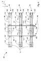
Figure 1 is a schematic front view of a machine for gluing porous material slabs in a first operating configuration; -
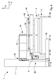
Figure 2 is a schematic side view of the machine inFigure 1 in the first operating configuration, in which some elements have been removed to better show others elements; -
Figure 3 is a schematic top view of the machine inFigure 1 in which some elements have been removed to better show others elements; -
Figure 4 is a top view of positioning guides included in the machine inFigure 1 ; -
Figure 5 is a schematic front view of the machine inFigure 1 in a second operating configuration; -
Figure 6 is a schematic side view of the machine inFigure 1 in the second operating configuration in which some elements have been removed to better show others elements; -
Figure 7 is a front view of a needle element; -
Figure 8 is an enlarged view ofFigure 7 ; -
Figure 9 is a side view of a needle of said needle element; -
Figure 10 is a enlarged schematic front view of a first embodiment of a glue-distributing means included in the machine inFigure 1 ; -
Figure 11 is an enlarged detail ofFigure 10 ; -
Figure 12 is a schematic front view of a second embodiment of glue-distributing means included in the machine inFigure 1 ; -
Figure 13 is a schematic front view of a third embodiment of glue-distributing means included in the machine inFigure 1 . -
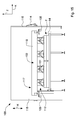
Figure 14 is a schematic side view of another embodiment of a machine for gluing porous material slabs in a first operating configuration, in which some elements have been removed to better show others elements; -
Figure 15 is a schematic side view of the machine inFigure 14 in a second operating configuration; -
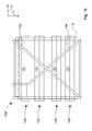
Figure 16 is a schematic plan view of the machine inFigure 14 ; -
Figure 17 is a schematic front view of the machine inFigure 14 ; -
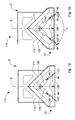
Figure 18 is a schematic front view of a gripping unit comprising a pair of needle elements in a retracted position; -
Figure 19 is a view like that ofFigure 18 in which the needle elements are in an extended position; -
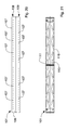
Figure 20 is a schematic bottom plan view of the gripping unit inFigure 18 ; -
Figure 21 is a schematic top plan view of the gripping unit inFigure 18 . - With reference to
Figures 1 to 3 , there is shown amachine 1 for gluing afirst slab 3 to asecond slab 4, both made of a porous material, for example latex rubber or polyurethane, for making a mattress 2 (Figure 5 ), or also, for example, insulating elements. In particular, thefirst slab 3 and thesecond slab 4, having a substantially equal width and length, respectively comprise a firstflat surface 77 and a secondflat surface 78 arranged for forming, once themattress 2 has been assembled, the external surfaces of the mattress. - Further, the
first slab 3 and thesecond slab 4 respectively comprise afirst coupling surface 7 and asecond coupling surface 13 respectively opposite the firstflat surface 77 and the secondflat surface 78. - In particular, the
first coupling surface 7 and thesecond coupling surface 13 each compriserespective recesses 66 andprojections 65 shaped so as to be couplable in a shapingly coupled manner. - The
aforesaid machine 1 comprises atubular base 15, of substantially rectangular shape, supported by a plurality offoot elements 16, the height of each one of which is adjustable. - From the
base 15 an upright 11 projects, which for example is made of sheet metal and has a parallelepipedon shape, extending substantially parallelly to a first axis Z that is substantially vertical. - The
machine 1 comprises supporting means 18, 22 that is suitable for supporting and moving gripping means 12 of theslabs - The supporting
means pneumatic cylinder 22 housed in the upright 11, and aslide 18 moved by thepneumatic cylinder 22 along the upright 11. - The
upright 11, which is internally hollow, comprises first guides 25 extending substantially parallelly to the first axis Z. - The first guides 25 are arranged for engaging with respective first sliding
blocks 21 fixed to anend portion 20 of theslide 18, theslide 18 projecting from the upright 11 substantially parallelly to a second axis X, which is substantially horizontal and perpendicular to the first axis Z. - In an embodiment of the invention that is not shown the
machine 1 comprises a gearmotor housed in theupright 11 and arranged for moving theslide 18 along theupright 11. - The
machine 1 further comprises positioning guides 38, shown in detail inFigure 4 , supported by theslide 18. - The positioning guides 38 comprise a
first guide element 42 and asecond guide element 47, that are substantially parallel to one another, extending substantially parallelly to the second axis X. - In particular, the
first guide element 42 and thesecond guide element 47 are mounted cantilevered on theslide 18. - The positioning guides 38 further comprise a
third guide element 39, afourth guide element 40 and afifth guide element 41 that are substantially parallel to one another and extend substantially parallelly to a third axis Y, which is substantially horizontal and perpendicular to the first axis Z, the first axis Z, the second axis X and the third axis Y forming a triad of Cartesian axes. - In particular, the
third guide element 39, thefourth guide element 40 and thefifth guide element 41 are slidably supported by thefirst guide element 42 and by thesecond guide element 47 substantially parallelly to the second axis X. - The
machine 1 further comprises movement means 46 for moving thethird guide element 39, thefourth guide element 40 and thefifth guide element 41 along the second axis X towards or away from one another, in function of a transverse dimension of thefirst slab 3. - In particular, the movement means 46 comprises crank means 146 acting on
ballscrews 147. - In an embodiment of the invention that is not shown the
third guide element 39, thefourth guide element 40 and thefifth guide element 41 are moved manually by an operator along the second axis X and locked by the operator in a desired position. - In a further embodiment of the invention, which is not shown, the
third guide element 39, thefourth guide element 40 and thefifth guide element 41 are automatically moved and locked along the second axis X by a servomechanism acting on theballscrews 147. - The
third guide element 39, thefourth guide element 40 and thefifth guide element 41 each support the gripping means 12 for grasping, in use, thefirst slab 3. - The gripping means comprises a plurality of
gripping units 12, in particular nine in the embodiment shown in the Figures, each of which comprises a pair ofneedle elements guide element gripping units 12. - In a further embodiment of the invention, which is not shown, it is provided that the
third guide element 39, thefourth guide element 40 and thefifth guide element 41 each support a number ofgripping units 12 that is less or more than three. - In a still further embodiment of the invention, which is not shown, the
third guide element 39, thefourth guide element 40 and thefifth guide element 41 are not provided and thegripping units 12 are slidably supported substantially parallelly to the second axis X by thefirst guide element 42 and by thesecond guide element 47. - In another embodiment of the invention, which is not shown, the
first guide element 42 and thesecond guide element 47 are not provided, whilst thethird guide element 39, thefourth guide element 40 and thefifth guide element 41 are mounted in a cantilevered manner on theslide 18 and slidably support the grippingunits 12 that are substantially parallelly to the third axis Y. - With reference to
Figures 7 to 9 , the needle elements comprise an elongated and substantiallyflat body 49, and a plurality of straight andflat needles 48 that are suitably spaced apart from one another, in particular at a reciprocal distance of 50 mm. Theneedles 48, aligned along a row, project from thebody 49, and viewed laterally, have an end portion shaped as a tip with an oblique side to enable better inside penetration of the porous material to be pierced. - In particular, each
needle 48 comprises anupper wall 48a, alower wall 48b that are substantially flat, parallel, opposite and connected by afirst side wall 48c and by asecond side wall 48d, which are also flat and opposite, as better shown inFigures 8 and 9 . Thefirst side wall 48c and thesecond side wall 48d, at the first ends thereof, are connected to thebody 49 by substantially equal connections R. Eachneedle 48 further comprises afirst oblique wall 48e, extending from thefirst side wall 48c, and asecond oblique wall 48f, extending from thesecond side wall 48d. Thefirst oblique wall 48e and thesecond oblique wall 48f, which are respectively connected to thefirst side wall 48c and to thesecond side wall 48d at the second ends thereof opposite the first ends, join together to form a vertex V of theneedle 48. It should be noted that thefirst side wall 48c and thesecond side wall 48d are separated by a first distance L1 measured substantially at the first ends thereof and by a second distance L2 measured substantially at the second ends thereof, the second distance L2 being less than the first distance L1. This confers a tapered shape to theneedle 48 that makes the needle particularly suitable for piercing material without damaging or spoiling the material. Theupper wall 48a and thelower wall 48b, which are substantially parallel to one another, are substantially respectively parallel to two opposite faces of thebody 49. Theupper wall 48a extends as far as the vertex V, whilst thelower wall 48b is connected to the vertex V by theoblique walls - In use, the
needle elements respective actuators 120 between an extended position D (Figure 19 ), in which theneedles 48 are arranged for penetrating thefirst slab 3, and a retracted position E (Figure 18 ), in which theneedles 48 are contained inside the gripping unit so as not to interact with thefirst slab 3. - The
needle elements element 36 comprising an abuttingwall 37 provided with a plurality of holes, which are not shown, arranged for being traversed by theneedles 48. In use, the abuttingwall 37 is arranged for abutting on thefirst surface 77 of thefirst slab 3 so as to exert pressure thereupon. - The supporting
element 36 comprises afurther wall 23, opposite thewall 37, and connectable to thethird guide element 39, to thefourth guide element 40 and to thefifth guide element 41 by means of a sliding block-guide connection. - In this manner, the supporting
element 36, and theneedle elements third guide element 39, by thefourth guide element 40 and by thefifth guide element 41 substantially parallelly to the third axis Y and to the second axis X, inasmuch as, as said above, thethird guide element 39, thefourth guide element 40 and thefifth guide element 41 are slidably supported substantially parallelly to the second axis X by thefirst guide element 42 and by thesecond guide element 47. - The
machine 1 further comprises, as shown inFigure 4 , further movement means 43 for moving the supportingelements 36, and thegripping units 12 therewith, along the third axis Y towards or away from one another, in function of a longitudinal dimension of thefirst slab 3. - In particular, the further movement means 43 comprises further crank means 143 acting on
further ballscrews 144. - In an embodiment of the invention, which is not shown, the supporting
elements 36, and thegripping units 12 therewith, are moved manually by an operator along the third axis Y and locked by the operator in a desired position. - In a further embodiment of the invention, which is not shown, the supporting
elements 36, and thegripping units 12 therewith, are moved, and locked, automatically along the third axis Y by a further servomechanism acting on thefurther ballscrews 144. - The
machine 1 further comprises acrosspiece element 9, shown inFigures 1 ,2 ,3 and6 , fixed to theupright 11 by means of a supportingarm 50 and a further supportingarm 51. - The
crosspiece element 9, extending substantially parallelly to the third axis Y, slidably supports afurther crosspiece element 8 that is movable substantially parallelly to the third axis Y by agearmotor 53. - The
further crosspiece element 8, extending substantially parallelly to the second axis X, slidably supports acarriage 54, shown in greater detail inFigure 10 . - The
carriage 54 is movable substantially parallelly to the second axis X by afurther gearmotor 56 and supports glue-distributingmeans 14 by arod element 60. - The glue-distributing
means 14, shown inFigures 10 and 11 , comprise afirst dispensing nozzle 58 and asecond dispensing nozzle 59 each arranged for spraying glue respectively on thefirst coupling surface 7 and on thesecond coupling surface 13. - In particular, the
first dispensing nozzle 58 and thesecond dispensing nozzle 59, which are of known type and are substantially structurally and functionally the same as one another, are mounted on therod element 60 rotated substantially by 180°, one facing upwards and the other facing downwards, so as to spray, in use, respectively a layer of glue on thefirst coupling surface 7 and on thesecond coupling surface 13. - The glue can be supplied to the
first dispensing nozzle 58 and to thesecond dispensing nozzle 59 by gravity if a tank containing glue, which is not shown, is positioned above the glue-distributingmeans 14. Alternatively, the glue can be pressurized by two pneumatic pumps, which are not shown in the Figures, supplied by pressurized air from a solenoid valve, which is not shown. The choice of supplying the glue to thefirst dispensing nozzle 58 and to thesecond dispensing nozzle 59 by gravity or by pressurization is a function of the type of glue used. In particular, in the case of glue with a water base with a single component it is possible to supply the glue by gravity, otherwise, in the case of glue with a solvent base or a water base with two components, it is opportune to pressurize the glue to supply the glue to thefirst dispensing nozzle 58 and to thesecond dispensing nozzle 59. - In an embodiment of the invention, which is not shown, the glue-distributing
means 14 comprises only one between thefirst dispensing nozzle 58 and thesecond dispensing nozzle 59. - In a further embodiment of the invention, which is not shown, the glue-distributing
means 14 comprises further dispensing nozzles in addition to thefirst dispensing nozzle 58 and to thesecond dispensing nozzle 59. - In a further embodiment of the invention, shown in
Figure 12 , the glue-distributingmeans 14 comprises abrush 69 connected to thecarriage 54 by asupport 74. - In this embodiment, a
first gearmotor 61 is provided acting on thesupport 74 for moving thebrush 69 substantially parallelly to the first axis Z, and a second gearmotor, which is not shown, for rotating thebrush 69 around an axis V that in use is substantially parallel to the first axis Z. - In this manner, it is possible to vary, in use, the distance between the
brush 69 and theslabs brush 69 to distribute the glue on theprojections 65 and in therecesses 66. - Further, in this still further embodiment, the glue is supplied to the
brush 69 by a pump, which is not shown, that pressurizes the glue by providing the glue with the thrust necessary for reaching thebrush 69. - In another embodiment of the invention, shown in
Figure 13 , the glue-distributingmeans 14 comprises a plurality ofbristles 72 projecting radially from a supportingshaft 71 connected by afurther support 73 to thecarriage 54. - In this embodiment, there is provided a
third gearmotor 75 acting on thefurther support 73 for moving the supportingshaft 71, and thebristles 72 therewith, substantially parallelly to the first axis Z, and afourth gearmotor 76, for rotating the supportingshaft 71, and thebristles 72 therewith, around a further axis T, substantially parallel, in use, to the third axis Y. - In this manner, it is possible to vary, in use, the distance between the
bristles 72 and theslabs bristles 72 to distribute the glue on theprojections 65 and in therecesses 66. - The
machine 1 further comprises conveyingmeans 5 for supporting and moving thefirst slab 3 and thesecond slab 4, provided with a plurality offurther foot elements 63, the height of which is adjustable (Figures 1 ,2 ,5 and6 ). - The conveying means 5 comprises a
conveyor belt 62 defining a workingplane 64 that is substantially parallel to the second axis X and to the third axis Y. - The
conveyor belt 62 is movable along an advance direction C, indicated by an arrow inFigures 1 and17 . - The
machine 1 further comprises a supply system, which is not shown, provided with a further conveyor belt for conveying thefirst slab 3 and thesecond slab 4 to theconveyor belt 62. - Also, the
machine 1 comprises an unloading system, which is not shown, provided with a still further conveyor belt for moving themattresses 2 away from theconveyor belt 62. - The movement of the
conveyor belt 62, of the further conveyor belt and of the still further conveyor belt is controlled by a plurality of photocells, which are not shown. - The
machine 1 further comprises a plurality of position sensors and of position transducers, so-called "encoders", to control the supporting means, i.e. theslide 18 and thepneumatic cylinder 22. Further sensors can be provided to control the other servomechanisms and gearmotors comprised in themachine 1. - The operation of the
machine 1 is disclosed below with particular reference toFigures 1 ,2 ,5 and6 . - Initially, the
first slab 3 is transferred from the further conveyor belt onto theconveyor belt 62, thefirst coupling surface 7 facing, and resting on, the workingplane 64. - Subsequently, the
slide 18 is lowered until the abuttingwalls 37 of the supportingelements 36 contact the firstflat surface 77 of thefirst slab 3, the gripping means 12 having theneedles 48 in a retracted position E so that they do not protrude outside the abuttingwalls 37. - Subsequently, the
needle elements needles 48 protrude outside the abuttingwall 37 such as to pierce the firstflat surface 77. - Still subsequently, as shown in
Figures 1 and2 , moving theslide 18 away from the workingplane 64 is provided so as to lift thefirst slab 3 from the workingplane 64. - Subsequently, positioning on the further conveyor belt a film made of plastics, which is not shown, is provided, the film made of plastics being arranged, in a subsequent gluing step, for preventing the glue from falling onto the working
plane 64. - Still subsequently, positioning the
second slab 4 on the film made of plastics and transferring thesecond slab 4 and the film made of plastics on the workingplane 64 is provided, thesecond slab 4 being positioned on theconveyor belt 62 such that the secondflat surface 78 faces and rests on the film made of plastics and thesecond coupling surface 13 faces thefirst coupling surface 7. - Subsequently, the
further crosspiece 8 and thecarriage 54 are driven to enable the glue-distributingmeans 14, suitably moved, to move along the entire extent of thefirst slab 3 and of thesecond slab 4 and to distribute the glue on thefirst coupling surface 7 and/or on thesecond coupling surface 13. - Still subsequently, the
further crosspiece element 8 is substantially positioned at anend 79 of thecrosspiece element 9. - Subsequently, the
slide 18 is moved along the first axis Z towards the workingplane 64 until so as to superimpose and press thefirst slab 3 onto thesecond slab 4, i.e. thefirst coupling surface 7 against the second coupling surface 13 (Figures 5 and6 ). In this step, the grippingunits 12 exert pressure on the firstflat surface 77 so as to enable the glue to be activated. - In addition, in this step, the
slide 18 is vibrated by thepneumatic cylinder 22 such as to promote gluing between thefirst slab 3 and thesecond slab 4. - Still subsequently, the
needles 48 are taken to the retracted position E and theslide 18 is subsequently moved away from the workingplane 64. - Subsequently, by the
conveyor belt 62, the thus formedmattress 2 is transferred to the still further conveyor belt, which moves themattress 2 away from theconveyor belt 62. - With reference to
Figures 14 to 17 , there is shown another embodiment of themachine 100 for gluingporous material slabs - The elements of this embodiment of the
machine 100 that are structurally and functionally similar to the corresponding elements of the previously disclosed embodiment will be indicated below by the same reference numbers. - The
machine 100 comprises gripping means 112 arranged for grasping theslabs gripping units 112. - Each
gripping unit 112, shown in greater detail inFigures 18 to 21 , comprises alongitudinal member 101 extending substantially parallelly to the third axis Y that has a length that is substantially equal to or greater than the extent of theslabs mattress 2, along the third axis Y. The grippingunits 112 are fixed by threaded connections to supportingmeans 102 that comprises a frame comprising in turn twobars frame 102 is movable by guidingwheel 105 that engages respective guiding elements along a movement direction K substantially parallel to the first axis Z. Theframe 102 can be moved by a chain, or a belt, driven, for example, by gearmotors. This combined system of guidingwheels 105 and chain enables thegripping units 112 to be moved almost always parallelly to the workingplane 64. - With reference to
Figures 18 to 21 , thelongitudinal members 101 have a cross section that is substantially triangular with the base side of the triangle formed by an abuttingwall 106 that is substantially parallel to the workingplane 64, i.e. substantially horizontal. The abuttingwall 106 is provided withopenings 107 aligned on tworows rows - The
openings 107 can be substantially mutually equidistant in the same row, in particular by a distance equal to 50 mm. Eachopening 107 is arranged for being traversed by one of theneedles 48, thus it should be noted that the distance between twoconsecutive openings 107 is substantially the same as the distance between twoconsecutive needles 48. The diameter of anopening 107 is slightly greater than the diameter of theneedle 48. - The gripping
units 112 further comprise two tiltedwalls longitudinal member 101. The tiltedwalls zones 116 in which material is removed in order to lighten thelongitudinal members 101. - Each
gripping unit 112 is arranged for housing a pair ofneedle elements abutting wall 106. - The
needle elements Figure 19 ) comprised between 60° and 120°, in particular comprised between 70° and 90°. - Further, they are arranged, for example, in a symmetrical and specular manner with respect to a longitudinal plane S that is substantially orthogonal to the supporting
plane 64 and parallel to the third axis Y. - The
machine 100 is shown inFigure 14 in a first raised operating configuration in which theslabs Figure 15 in a second lowered operating configuration in which theslabs Figure 16 ). - The
machine 100 comprises thefirst dispensing nozzle 58 and thesecond dispensing nozzle 59 that are slidably supported by abridge element 117. Thebridge element 117, which is movable substantially parallelly to the third axis Y, comprises guides extending along the second axis X obtained on acrosspiece element 118 of thebridge element 117 and arranged for enabling the dispensingnozzles first dispensing nozzle 58 and thesecond dispensing nozzle 59 are mounted on thebridge element 117 aligned substantially vertically, i.e. rotated substantially by 180°, one facing upwards and the other facing downwards so as to distribute, in use, glue respectively on thefirst coupling surface 7 and on thesecond coupling surface 13. - The
machine 100 comprises acontrol panel 114 and aprotection structure 115 shown inFigures 14 and15 . Theprotection structure 115 is arranged for ensuring operation of themachine 100 in security by preventing access to the workingplane 64 by operators whilst themachine 100 is operating. - In a further embodiment of the invention, which is not shown, the gripping
means 12 is helped by suction-cup means to move theporous material slabs - In a still another embodiment of the invention, which is not shown, the gripping means may comprise a number of
gripping units 112 other than four, in particular greater or less than four. - In a further embodiment of the invention, which is not shown, the
longitudinal members 101 may have a cross section having any polygonal shape other than the triangular shape, or a circular or elliptical shape. - The operation of the
machine 100 provides initially that theframe 102 and thegripping units 112 are arranged in a raised position and, after thefirst slab 3 is transferred onto the workingplane 64 by conveyor belts, the gearmotor that moves the chains is driven so as to lower the grippingunits 112 until the abuttingwalls 106 thereof contact the firstflat surface 77 of thefirst slab 3, theneedles 48 housed in the supporting-bar elements 101 being in a retracted position E so as not to protrude outside the abuttingwalls 106. - Subsequently, the
actuators 120 arrange theneedle elements 48 in an extended position D in which theneedles 48 protrude outside thefirst walls 106 piercing the firstflat surface 77 and thus thefirst slab 3. - Still subsequently, as shown in
Figures 14 and17 , the grippingunits 112 are moved away from the workingplane 64, so as to lift thefirst slab 3 from the workingplane 64. It should be noted that the grippingunits 112 enable thefirst slab 3 to be lifted along the movement direction K so that thefirst slab 3 always remains planar, i.e. parallel to the workingplane 64. In other words, despite the peculiarity of flexibility of the porous material, it is in this manner possible to raise the porous material as if it acted as a stiff body. - Subsequently, after positioning the
second slab 4 on the workingplane 64, thebridge element 117 is moved along the advance direction C to enable the glue-distributingmeans 14, which is suitably moved along the guides obtained on thecrosspiece element 118, to move along the entire extent of thefirst slab 3 and of thesecond slab 4 and to distribute glue on thefirst coupling surface 7 and on thesecond coupling surface 13, in particular in corresponding points of the twoslabs - Subsequently, the gripping
units 112 is lowered along the first axis Z towards the workingplane 64 until thefirst slab 3 is superimposed on the second slab 4 (Figure 15 ). In this manner, owing to the substantially uniform pressure exerted vertically by the abuttingwalls 106 on the firstflat surface 77, thefirst coupling surface 7 is pressed against thesecond coupling surface 13 so as to enable the glue to be activated and thus to obtain an effective mutual gluing of theslabs - Still subsequently, the
needles 48 are retracted and subsequently thegripping units 112 are moved away from the workingplane 64 so as to return thegripping units 112 to the raised position. - Subsequently, the
mattress 2 thus formed is transferred by theconveyor belt 62 onto an outlet conveyor belt that moves the thus formedmattress 2 away from the workingplane 64. - It should be noted how the
machine mattresses 2 to be formed rapidly and effectively. - In fact, the invention illustrates a
machine porous material slabs slabs - The machine according to the invention, owing to the
needle elements slabs slabs needle elements slabs needle elements slabs needles 48. It should be noted that theneedles 48 enable even very thinporous material slabs - In other words, the
machine 1 enables the operations that are usually performed manually by one or more operators to be significantly reduced and even eliminated. - Further, the glue-distributing
means 14, comprising for example the dispensingnozzles first coupling surface 7 and/or thesecond coupling surface 13, which enables thefirst slab 3 to be glued effectively to thesecond slab 4. - It should be noted that the gripping
units slabs - Variants and/or additions to what has been disclosed above and/or to what has been shown in the attached drawings are also possible.
Claims (15)
- Machine for gluing porous material slabs (3, 4), in particular for making a mattress (2) or an insulating element, comprising a working plane (64) for supporting a first porous material slab (3) and a porous material second slab (4), glue-distributing means (14) that is movable for distributing glue on said first slab (3) and/or on said second slab (4), and gripping means (12; 112) for grasping and moving said first slab (3) and/or said second slab (4), characterised in that said gripping means comprises at least a gripping unit (12; 112) provided with a pair of needle elements (49, 48) arranged alongside and divergent, said needle elements being movable linearly between an extended position (D) in which said needle elements interact with, in particular pierce, said slabs (3, 4) and a retracted position (E) in which said needle elements do not interact with said slabs (3, 4).
- Machine according to claim 1, wherein each needle element comprises an elongated, in particular substantially flat, body (49), provided with at least a needle (48) of almost flat shape.
- Machine according to claim 2, wherein said needle element comprises a plurality of needles (48) fixed to said body (49) spaced apart and aligned along at least a row (108, 109).
- Machine according to any preceding claim, in which said needle elements (48, 49) are arranged divergently so as to form an angle (α) comprised between 60° and 120°, in particular comprised between 70° and 90°.
- Machine according to any one of claims 2 to 4, wherein said needle (48) is substantially straight.
- Machine according to any preceding claim, wherein said gripping unit (12) comprises actuating means (120) for driving said needle elements (48, 49) between said extended position (D) and said retracted position (E).
- Machine according to any preceding claim, wherein said gripping unit (12; 112) comprises an abutting wall (37; 106) substantially parallel to said working plane (64) and arranged for abutting on and pressing said slabs (3, 4) such as to enable the applied glue to be activated so as to glue said first slab (3) to said second slab (4).
- Machine according to claim 7, wherein said abutting wall (37; 106) comprises openings (107) for the passage of said needle elements (48, 49).
- Machine according to any preceding claim, wherein said gripping means comprises a plurality of gripping units (12, 112) arranged parallel and spaced apart from one another.
- Machine according to any preceding claim, comprising supporting means (18, 22; 102) for supporting and moving said gripping means (12; 112) with respect to said working plane (64).
- Machine according to any preceding claim, wherein said glue-distributing means (14) is movable parallelly to said working plane (64) and comprises means (58, 59; 69; 72) for distributing glue on a first surface (7) of said first slab (3) and on a second surface (13) of said second slab (4).
- Method for gluing porous material slabs (3, 4), in particular for making a mattress (2) or an insulating element, comprising grasping a first porous material slab (3) and lifting the first porous material slab above a second porous material slab (4), distributing glue at least on a first surface (7) of said first slab (3) and/or a second surface (13) of said second slab (4), lowering said first slab (3) and superimposing the first slab on said second slab (4), characterised in that the method further comprises pressing together said first slab (3) and said second slab (4) with a set pressure to enable said glue to be activated so as to glue said slabs (3, 4).
- Method according to claim 12, wherein said pressing comprises exerting a pressure that is uniform and distributed over the entire extent of said first slab (3).
- Method according to claim 12 or 13, wherein said grasping comprises piercing said first slab (3) by needle elements (48, 49) arranged mutually alongside and divergent.
- Method according to any preceding claim, wherein said grasping, lifting and lowering comprises maintaining said first slab (3) substantially planar and parallel to said second slab (4).
Applications Claiming Priority (1)
| Application Number | Priority Date | Filing Date | Title |
|---|---|---|---|
| IT000200A ITMO20080200A1 (en) | 2008-07-23 | 2008-07-23 | MACHINE FOR GLUE SHEETS IN POROUS MATERIAL |
Publications (2)
| Publication Number | Publication Date |
|---|---|
| EP2147775A2 true EP2147775A2 (en) | 2010-01-27 |
| EP2147775A3 EP2147775A3 (en) | 2011-03-23 |
Family
ID=40673645
Family Applications (1)
| Application Number | Title | Priority Date | Filing Date |
|---|---|---|---|
| EP09166279A Withdrawn EP2147775A3 (en) | 2008-07-23 | 2009-07-23 | Machine and method for gluing porous material slabs |
Country Status (2)
| Country | Link |
|---|---|
| EP (1) | EP2147775A3 (en) |
| IT (1) | ITMO20080200A1 (en) |
Cited By (14)
| Publication number | Priority date | Publication date | Assignee | Title |
|---|---|---|---|---|
| CN102909815A (en) * | 2012-08-20 | 2013-02-06 | 青岛鸿铭机械有限责任公司 | Curing mechanism of foam board curing machine |
| EP2957350A1 (en) | 2014-06-17 | 2015-12-23 | Aper S.r.l. | Gluing method and apparatus |
| US20160213161A1 (en) * | 2015-01-23 | 2016-07-28 | Dreamwell, Ltd. | Mattress manufacturing process and apparatus |
| CN106904434A (en) * | 2017-04-14 | 2017-06-30 | 浙江工业大学 | The viscose glue grabbing device that hinge stent drives |
| CN107009636A (en) * | 2017-05-26 | 2017-08-04 | 合肥福映光电有限公司 | Openning sticker adsorption device |
| US9839301B2 (en) | 2015-01-23 | 2017-12-12 | Dreamwell, Ltd. | Mattress manufacturing process and apparatus |
| US9862553B2 (en) | 2015-01-23 | 2018-01-09 | Dreamwell, Ltd. | Mattress manufacturing process and apparatus |
| CN107651416A (en) * | 2017-09-15 | 2018-02-02 | 严传玉 | A kind of spot gluing equipment assembles charging & discharging machine |
| WO2018200679A1 (en) * | 2017-04-28 | 2018-11-01 | Sealy Technology, Llc | Assembly for and method of automated manufacture of multi-layer foam laminate mattresses |
| US10272611B2 (en) | 2015-01-23 | 2019-04-30 | Dreamwell, Ltd. | Mattress manufacturing process and apparatus |
| US10365638B2 (en) | 2015-01-23 | 2019-07-30 | Dreamwell, Ltd. | Scheduling process for automated mattress manufacturing |
| US10455950B2 (en) | 2015-01-23 | 2019-10-29 | Dreamwell, Ltd. | Mattress manufacturing process and apparatus |
| US10525557B2 (en) | 2015-01-23 | 2020-01-07 | Dreamwell, Ltd. | Automated mattress manufacturing process and apparatus |
| US10696540B2 (en) | 2015-04-15 | 2020-06-30 | Dreamwell, Ltd. | Coil string staging area apparatus and method |
Family Cites Families (15)
| Publication number | Priority date | Publication date | Assignee | Title |
|---|---|---|---|---|
| JPS6032575B2 (en) * | 1979-02-20 | 1985-07-29 | 三菱化学株式会社 | Welding equipment for large synthetic resin molded products |
| US4397898A (en) * | 1980-10-20 | 1983-08-09 | Manville Service Corporation | Thick batt of fibrous insulation |
| JPH064178B2 (en) * | 1985-01-21 | 1994-01-19 | トヨタ自動車株式会社 | Mold used for bonding disappearing model for casting |
| US4595446A (en) * | 1985-04-24 | 1986-06-17 | Tape, Inc. | Solvent bonding process utilizing spray-mist |
| DD258407A1 (en) * | 1987-03-12 | 1988-07-20 | Karl Marx Stadt Tech Hochschul | DEVICE FOR ASSOCIATING AND DISCONNECTING A DOUBLE LAYER |
| US4805949A (en) * | 1987-10-19 | 1989-02-21 | Prab Robots, Inc. | Material-handling apparatus |
| DE8811030U1 (en) * | 1988-09-01 | 1988-10-20 | Spühl (Deutschland) GmbH, 6800 Mannheim | Needle gripper |
| DE3907104A1 (en) * | 1989-03-04 | 1990-09-06 | Joachim Neuberg | Device for conveying samples to a gluing station |
| DE4107003A1 (en) * | 1991-03-05 | 1992-09-10 | Kuenkel Wagner & Co | TWO OR MULTI-PIECE MODEL MADE OF FOAMED PLASTIC FOR USE IN THE FULL MOLDING METHOD AND METHOD FOR THE PRODUCTION THEREOF |
| JPH06298437A (en) * | 1993-04-16 | 1994-10-25 | Ngk Insulators Ltd | Gripping device for softened plate-shaped body and stacking device using it |
| FR2710864B1 (en) * | 1993-10-06 | 1995-12-08 | Pont A Mousson | Method and installation for assembling parts of gasifiable models used in foundries. |
| FR2714036B1 (en) * | 1993-12-22 | 1996-03-08 | Saint Gobain Isover | Gripper for fibrous materials. |
| US6254716B1 (en) * | 1999-10-25 | 2001-07-03 | Sony Corporation | Apparatus and method for use in the manufacture of multiple layer optical disc |
| KR100493384B1 (en) * | 2002-11-07 | 2005-06-07 | 엘지.필립스 엘시디 주식회사 | structure for loading of substrate in substrate bonding device for manucturing a liquid crystal display device |
| NO324032B1 (en) * | 2005-10-21 | 2007-07-30 | Sinvent As | Arrangement and method for gripping, holding and releasing penetrable objects |
-
2008
- 2008-07-23 IT IT000200A patent/ITMO20080200A1/en unknown
-
2009
- 2009-07-23 EP EP09166279A patent/EP2147775A3/en not_active Withdrawn
Cited By (19)
| Publication number | Priority date | Publication date | Assignee | Title |
|---|---|---|---|---|
| CN102909815A (en) * | 2012-08-20 | 2013-02-06 | 青岛鸿铭机械有限责任公司 | Curing mechanism of foam board curing machine |
| CN102909815B (en) * | 2012-08-20 | 2015-01-21 | 青岛鸿铭机械有限责任公司 | Curing mechanism of foam board curing machine |
| EP2957350A1 (en) | 2014-06-17 | 2015-12-23 | Aper S.r.l. | Gluing method and apparatus |
| CN107207239A (en) * | 2015-01-23 | 2017-09-26 | 美梦有限公司 | Mattress manufacture method and apparatus |
| US20160213161A1 (en) * | 2015-01-23 | 2016-07-28 | Dreamwell, Ltd. | Mattress manufacturing process and apparatus |
| CN107207239B (en) * | 2015-01-23 | 2020-10-23 | 美梦有限公司 | Mattress manufacturing method and apparatus |
| US10365638B2 (en) | 2015-01-23 | 2019-07-30 | Dreamwell, Ltd. | Scheduling process for automated mattress manufacturing |
| US9839301B2 (en) | 2015-01-23 | 2017-12-12 | Dreamwell, Ltd. | Mattress manufacturing process and apparatus |
| US9862553B2 (en) | 2015-01-23 | 2018-01-09 | Dreamwell, Ltd. | Mattress manufacturing process and apparatus |
| US10525557B2 (en) | 2015-01-23 | 2020-01-07 | Dreamwell, Ltd. | Automated mattress manufacturing process and apparatus |
| US10172474B2 (en) * | 2015-01-23 | 2019-01-08 | Dreamwell, Ltd. | Mattress manufacturing process and apparatus |
| US10455950B2 (en) | 2015-01-23 | 2019-10-29 | Dreamwell, Ltd. | Mattress manufacturing process and apparatus |
| US10272611B2 (en) | 2015-01-23 | 2019-04-30 | Dreamwell, Ltd. | Mattress manufacturing process and apparatus |
| US10696540B2 (en) | 2015-04-15 | 2020-06-30 | Dreamwell, Ltd. | Coil string staging area apparatus and method |
| CN106904434A (en) * | 2017-04-14 | 2017-06-30 | 浙江工业大学 | The viscose glue grabbing device that hinge stent drives |
| WO2018200679A1 (en) * | 2017-04-28 | 2018-11-01 | Sealy Technology, Llc | Assembly for and method of automated manufacture of multi-layer foam laminate mattresses |
| CN107009636A (en) * | 2017-05-26 | 2017-08-04 | 合肥福映光电有限公司 | Openning sticker adsorption device |
| CN107651416B (en) * | 2017-09-15 | 2019-02-12 | 南昌明高科技有限公司 | A kind of spot gluing equipment assembling charging & discharging machine |
| CN107651416A (en) * | 2017-09-15 | 2018-02-02 | 严传玉 | A kind of spot gluing equipment assembles charging & discharging machine |
Also Published As
| Publication number | Publication date |
|---|---|
| ITMO20080200A1 (en) | 2010-01-24 |
| EP2147775A3 (en) | 2011-03-23 |
Similar Documents
| Publication | Publication Date | Title |
|---|---|---|
| ITMO20080200A1 (en) | MACHINE FOR GLUE SHEETS IN POROUS MATERIAL | |
| EP0111206B1 (en) | Method and apparatus for panel wiping or coating operation | |
| EP3863470B1 (en) | A lifting table and a method of operating and cleaning a lifting table | |
| EP2401217B1 (en) | Apparatus for handling layers of palletised goods | |
| EP3812320B1 (en) | Stacking device | |
| EP2289826B1 (en) | Manually controlled depalletizing machine | |
| KR102542589B1 (en) | Automatic devices for harvesting mushroom in a bottle | |
| KR20100033273A (en) | Apparatus and method for automatically suctioning stacked box and transfering it | |
| KR20180128960A (en) | Transfer device, manufacturing line using same, and method of changing manufacturing line | |
| WO2008138947A2 (en) | Method and device for packing large drinks packs | |
| KR20080079240A (en) | Peeling method of a plate-shaped object and its apparatus | |
| CN113979117B (en) | Seat frame automatic parcel system | |
| WO2005105353A1 (en) | Wire saw processing machine | |
| CN102497937B (en) | Operating device | |
| JP2005270740A (en) | Adhesive coating apparatus and adhesive coating method | |
| KR20100112703A (en) | Food container moving device | |
| KR200467365Y1 (en) | Apparatus for eliminating foreign substance in cosmetic container | |
| KR101691506B1 (en) | Four polystyle lift type stone automatic adsorption conveying and stacking apparatus | |
| KR101485986B1 (en) | flow coating apparatus | |
| KR101022610B1 (en) | Pipe automatic washing device | |
| KR101720699B1 (en) | Apparatus and method attaching for nature wood-pattern | |
| KR102248817B1 (en) | Transfer system for laser cutting object | |
| JP2013255889A (en) | Device for applying liquid | |
| AU2014221295A1 (en) | A pallet washing machine | |
| US6022439A (en) | Method for assembling a pair of members |
Legal Events
| Date | Code | Title | Description |
|---|---|---|---|
| PUAI | Public reference made under article 153(3) epc to a published international application that has entered the european phase |
Free format text: ORIGINAL CODE: 0009012 |
|
| AK | Designated contracting states |
Kind code of ref document: A2 Designated state(s): AT BE BG CH CY CZ DE DK EE ES FI FR GB GR HR HU IE IS IT LI LT LU LV MC MK MT NL NO PL PT RO SE SI SK SM TR |
|
| AX | Request for extension of the european patent |
Extension state: AL BA RS |
|
| PUAL | Search report despatched |
Free format text: ORIGINAL CODE: 0009013 |
|
| AK | Designated contracting states |
Kind code of ref document: A3 Designated state(s): AT BE BG CH CY CZ DE DK EE ES FI FR GB GR HR HU IE IS IT LI LT LU LV MC MK MT NL NO PL PT RO SE SI SK SM TR |
|
| AX | Request for extension of the european patent |
Extension state: AL BA RS |
|
| 17P | Request for examination filed |
Effective date: 20110923 |
|
| RAP1 | Party data changed (applicant data changed or rights of an application transferred) |
Owner name: APER S.R.L. |
|
| 17Q | First examination report despatched |
Effective date: 20120223 |
|
| STAA | Information on the status of an ep patent application or granted ep patent |
Free format text: STATUS: THE APPLICATION IS DEEMED TO BE WITHDRAWN |
|
| 18D | Application deemed to be withdrawn |
Effective date: 20120905 |