EP2147646A2 - Instrument médical doté d'un système d'étanchéité flexible - Google Patents
Instrument médical doté d'un système d'étanchéité flexible Download PDFInfo
- Publication number
- EP2147646A2 EP2147646A2 EP09166106A EP09166106A EP2147646A2 EP 2147646 A2 EP2147646 A2 EP 2147646A2 EP 09166106 A EP09166106 A EP 09166106A EP 09166106 A EP09166106 A EP 09166106A EP 2147646 A2 EP2147646 A2 EP 2147646A2
- Authority
- EP
- European Patent Office
- Prior art keywords
- medical instrument
- seal
- instrument according
- lamellae
- expansion cone
- Prior art date
- Legal status (The legal status is an assumption and is not a legal conclusion. Google has not performed a legal analysis and makes no representation as to the accuracy of the status listed.)
- Granted
Links
Images





Classifications
-
- A—HUMAN NECESSITIES
- A61—MEDICAL OR VETERINARY SCIENCE; HYGIENE
- A61B—DIAGNOSIS; SURGERY; IDENTIFICATION
- A61B17/00—Surgical instruments, devices or methods
- A61B17/34—Trocars; Puncturing needles
- A61B17/3462—Trocars; Puncturing needles with means for changing the diameter or the orientation of the entrance port of the cannula, e.g. for use with different-sized instruments, reduction ports, adapter seals
-
- A—HUMAN NECESSITIES
- A61—MEDICAL OR VETERINARY SCIENCE; HYGIENE
- A61B—DIAGNOSIS; SURGERY; IDENTIFICATION
- A61B17/00—Surgical instruments, devices or methods
- A61B17/34—Trocars; Puncturing needles
- A61B17/3462—Trocars; Puncturing needles with means for changing the diameter or the orientation of the entrance port of the cannula, e.g. for use with different-sized instruments, reduction ports, adapter seals
- A61B2017/3464—Trocars; Puncturing needles with means for changing the diameter or the orientation of the entrance port of the cannula, e.g. for use with different-sized instruments, reduction ports, adapter seals with means acting on inner surface of valve or seal for expanding or protecting, e.g. inner pivoting fingers
Definitions
- the present invention relates to a medical instrument with a cannula through which shafts of other instruments with different shaft diameters can be passed, with a seal having an opening with a variable opening cross section, through which the shafts with different shaft diameters are tightly passed, with a spreading device for Spreading the opening of the gasket, the spreading device having an expansion cone having a plurality of blades which are pivotally mounted on a ring body and form a proximally distally tapered expansion body, which communicates with the seal in the region of the opening.
- Such a medical instrument is from the EP 0 696 459 B1 known.
- This medical instrument is a trocar used in minimally invasive surgery.
- the corresponding trocar is passed through a small opening, e.g. can be induced by a small incision, introduced into the body of the patient by means of a trocar.
- shafts from other instruments used for the surgical procedure are then inserted through this trocar.
- These instruments include e.g. Gripping tools, coagulation instruments, endoscopes and the like. These have different diameters.
- an elastic conical seal is arranged in the trocar, which tapers from proximal to distal.
- the expansion cone is arranged proximally of this seal. An instrument inserted into the expansion cone expands it radially and expands the opening in the seal.
- the expansion cone also prevents damage to the seal when inserting sharp-edged instruments, because it can be made of a hard material. In this way, the seal is protected by the expansion cone.
- the slats are pivotally mounted on a ring, resulting in the conical body of the expansion cone and the slats can be pivoted radially.
- they have at one end axle pins with which the slats must be hinged in corresponding recesses in the ring body.
- each lamella thus requires exactly shaped sections with axle pins.
- the ring body must have correspondingly accurately shaped suspension devices, wherein in addition a precisely shaped cover must be placed on the device so that the slats do not fall off the ring.
- the design therefore requires several precisely manufactured items with relatively complex details. This is particularly difficult due to the small size of the components, which is in the millimeter range and therefore makes the construction consuming. The same applies to the assembly, in which the very small axle pins must be hung in the corresponding recesses in the ring body.
- the object is achieved on the one hand, that the lamellae are connected via film hinges with the annular body.
- the movable connection between lamellae and ring body by means of film hinges allows the production of the expansion cone as a single workpiece by an injection molding process. As a result, the necessary effort for producing the expansion cone is greatly reduced, since only a single part must be produced and no assembly of individual parts is necessary. This saves time and costs.
- the object is achieved by the fact that the lamellae have ball heads, via which they can be suspended in corresponding openings in the ring body.
- the expansion cone consists of several parts, the provision of ball heads, which must be inserted into the corresponding openings of the annular body, but represents a simple constructional measure.
- the ball heads are inserted without special attention in the openings of the ring body, whereby the assembly is easy.
- the ball heads of the slats are held by a cover ring in the ring body.
- cover ring prevents accidental dropping of the ball joint-mounted blades from the ring body. It also supports the concept of simple construction, as the cover ring provides a secure support for the ball joint-mounted blades.
- the seal extends distally away from the distal end of the expansion cone.
- this structural arrangement has the advantage that on the one hand, the joining of expansion cone and seal is easy, since both components are connected to each other via easily accessible outer sides.
- the present arrangement of the seal supports the removal of tissue samples, as it represents in this way a funnel-like shape, which tapers from distal to proximal. If e.g. taken with a gripping tool such a sample and then guided by the trocar sleeve to the proximal end, so this finally reaches the sealing system. There, it is guided due to the gradually decreasing diameter of the seal to the proximal narrow opening of the seal and possibly adapted in the form. An unwanted snagging due to an abrupt change in diameter in the course of extraction of the sample is thus avoided.
- the seal surrounds the expansion cone.
- This embodiment leads to a compact sealing system. Due to its small size, it is compatible with many known trocar systems. Because it Because of its compact design, it can also be easily inserted into the trocar system.
- the distal end of the fins of the expansion cone is positively connected to a socket at the edge of the opening in the seal.
- connection of the distal end of the slats with the socket at the edge of the opening of the seal slipping of the slats during spreading of the seal is prevented.
- a possible release of the slats is counteracted by the edge and ensures a uniform spreading.
- the connection causes the lamellae to move back together with the seal opening due to the restoring force of the spread elastic seal after removal of a shaft from the trocar back to the starting position.
- the distal end of the fins of the expansion cone is glued to the seal.
- Adhesion between the fins and the opening of the seal ensures permanent permanent contact between the components. As a result, an unwanted separation of the components is prevented, so that the lamellae are always arranged at the opening of the seal.
- Gluing is conceivable as a single measure, but also in combination with the positive connection.
- the seal is arranged together with the expansion cone in an enveloping body.
- the use of an envelope gives the system of expansion cone and seal increased stability.
- the assembly of the expansion cone of rigid material and the seal of elastic material is a relatively unstable in the lateral direction structure. This is particularly pronounced in the embodiment in which expand cone and seal starting from the joint with each other diametrically away from each other. A laterally offset or obliquely inserted into the expansion cone instrument would cause a lateral deflection or a lateral offset of the assembly.
- the enveloping body counteracts, but allows a degree of flexibility.
- the enveloping body consists of a double ball joint, which preferably consists of a seal holder, a central portion having ball sections and a proximal ball socket.
- the design of the enveloping body in the form of a somewhat movable double ball joint allows the expansion cone and associated with this seal to perform certain tilting or offset movements. This is especially useful for instruments whose shanks have a small diameter. For instruments with thin shafts, there may be an offset from the central passageway through the opening of the seal. Furthermore, in particular in the case of thin bendable shanks, a crooked course of the shank in the trocar can occur. Both result in that the seal does not come evenly on the entire circumference of the shaft with this in contact. The result would be unwanted leaks.
- the sealing system can shift so that the shaft again runs centrally through the opening of the seal. As a result, the desired tightness of the trocar system is obtained.
- the enveloping body consists of a flexible cladding tube.
- the flexible cladding tube consists of a substantially parallel juxtaposition of ring elements, wherein preferably two adjacent ring elements are connected to each other at two radially opposite locations and further the connection points of a ring element to the distal next ring element in each case by 90 ° relative to the Connection points are arranged offset in a circle to the proximal next ring element.
- the alternately offset by 90 ° arranged connecting points between the ring elements allow flexibility of the cladding tube in all lateral directions, since due to the radially opposite arrangement of the connection points, the associated ring elements have a tilting axis. By this they can be tilted from the mutually parallel arrangement at circumferentially lying between the connection points points to each other.
- the offset by 90 ° from one to the next pair of ring elements ensures in the overall arrangement of the ring elements that a tilting in two directions perpendicular to each other is possible. That is, the enveloping body thus produced can be moved at its free proximal end in two independent directions and thus in the plane given by these directions.
- the offset by 90 ° to each other arranged joints simultaneously good axial stability, as in the case of load, an equal distribution of the forces acting.
- Another advantage of using ring elements is that they are less demanding to manufacture, which makes manufacturing easy.
- the compounds are flexible webs.
- the advantage of this embodiment is that the narrow and therefore flexible webs are arranged directly without multi-part joints to the respective elements.
- the flexible cladding thus constructed can be formed as a single workpiece, e.g. made of plastic by an injection molding process. Since this eliminates a subsequent mounting of the ring elements, the production is very quick and easy.
- the compounds are Kippgelenke.
- the length of the flexible cladding tube is variable. It can thus be adapted in the construction of a sealing system to the length of the expansion cone and to the length of the seal. With a ring element type thus different lengths of ducts can be constructed, which makes this embodiment very variable.
- the ring elements at the locations of a Kippgelenk are at the locations of a Kippgelenk raised than those of a Kippgelenkconses.
- the position of the Kippgesch charged in the ring element must, in order to accommodate the complete Kippgelenkenkffy can have a certain height. This height is lower at the remaining points of the ring element. As a result, the area in which the ring elements can be tilted relative to one another is increased, since the distance between the ring elements is greater at the points lying circumferentially between the tilting joints. In this way, the greatest possible angle of inclination is achieved, which increases the flexibility of the cladding tube. This allows the sealing system to better adapt to any misalignment of a shaft in the opening of the seal.
- the flexible cladding tube widens conically from proximal to distal.
- the enveloping body is adapted to the average difference between the annular body of the expansion cone and the generally larger-diameter distal end of the seal.
- a good grip on the distal end of the seal and the trocar housing on which it is arranged and on the other hand ensures the expansion cone. This leads to the desired stability.
- the expansion cone consists of eight to twelve, preferably ten lamellae.
- the individual lamellae taper from proximal to distal.
- the expansion cone should have a surface that is as closed as possible in order to avoid any free spaces when inserting a shaft offer, through which the shaft can reach the seal and thus possibly damaged. Since there is a conical body, the circumference of the ring body is significantly greater than at the level of the opening of the seal. In the case of lamellae which constantly have the same width in the course and in which a closed surface should already be present on the ring body, this leads to the fact that the lamellae overlap at the distal end of the expansion cone. This in turn can cause the slats tilt and thus hinder the operation of the expansion cone.
- the lamellae, the annular body and the enveloping body are made of hard plastic.
- the seal is made of an elastic material.
- a resilient material for the seal allows on the one hand a suitable expansion of the opening of the seal by the expansion cone during insertion of the shank of an instrument and on the other hand a simultaneous optimal seal on the shaft of such an instrument due to the tight contact between the elastic material and shaft. This is achieved in particular by that the spread opening of the seal is pressed circumferentially against the inserted shaft due to the restoring force of the elastic material.
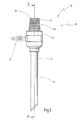
- a medical instrument shown in the figures is designated in its entirety by the reference numeral 10.
- the medical instrument 10 shown is a trocar and has distally a trocar sleeve 11, which is formed here by a cannula 12, a trocar housing 27 in the middle and a sealing system 18 arranged proximal thereto.
- Fig. 1 further shows a arranged on Trokargeophuse 28 valve 17, which can serve as a supply line for gases, for example. These are used to insufflate the surgical site to thereby obtain better access to the organs, vessels, tissues or the like on which the operation is to be performed.
- a self-closing closure 29 is arranged distally of the sealing system 18 (FIG. Fig. 2 ). This closes the proximal opening as soon as no shaft is inserted into the medical instrument 10.
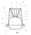
- the sealing system 18 a seal 14. This is fastened with a sealing edge 37 by a fastening ring 36 to a seal holder 28, with which the sealing system 18 is attached to the trocar housing 27. It extends proximally away from the seal holder 28 and thereby tapers.
- the seal 14 has an opening 16 and a socket 30 surrounding this opening 16 (FIG. Fig. 5 and 7 ). Attached to the socket 30 and extending proximally away from the seal 14 is an expansion cone 20 ( Fig. 5 ).
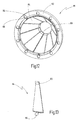
- this expansion cone 20 of an annular body 24, are arranged on the slats 22 by means of film hinges 34 pivotally aligned annular distally constructed.
- These lamellae 22 have at the distal end terminations 32, which can be positively connected to the socket 30 of the seal 14. Due to the cross-sectional difference between the annular body 24 and the socket 30 of the expansion cone 20 receives its conical shape.
- the lamellae 22 taper from proximal to distal in such a way that a uniform, almost closed inner surface of the expansion cone 20 results in the unexpanded state.
- the lamellae 22 are initially pressed radially outward upon insertion of a shank thereby simultaneously expanding the opening 16 of the seal 14, without, however, being splayed directly through the shaft itself.
- the structure of the seal 14 and the expansion cone 20 is enveloped by a cladding tube 26.
- this cladding tube 26 is connected distally to the seal holder 28 and proximally to the annular body 24 ( Fig. 5 ).
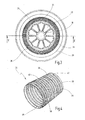
- the cladding tube 26 consists of individual ring elements 38, which are connected to each other via radially opposite webs 40 ( Fig. 4 ). In order to obtain a flexibility of the cladding tube, this is made on the one hand from a sufficiently elastic material, so that a flexibility of the webs 40 is given and the webs 40 also arranged offset from one another to the next pair of ring elements each by 90 ° to each other.
- an additional cap which has a continuous outer surface. As a result, the permeable cladding tube 26 is closed, so that no impurities can penetrate into the intermediate space between cladding tube 26 and expander cone 20 and seal 14 and settle.
- the seal 66 is arranged so that it tapers from proximal to distal, thereby surrounding the expansion cone 20.
- it is arranged with a fastening ring 68 on a Trokargecher 64, to which also proximal of the annular body 24 of the expansion cone 20 is attached.
- the distal end of the seal 66 forms an opening 70 which is surrounded by a socket 72.
- the terminations 32 of the slats 22 are arranged positively.
- FIG. 9 Another embodiment of a flexible cladding tube is in Fig. 9 shown.
- cladding tube 73 which is constructed of separate ring elements 74.
- These ring elements 74 have two different sides. While one side has two Kippgelenk conducteden 80, the other side has two Kippgelenkein accounts 78.
- the Kippgelenkein accounts 78 and the Kippgelenk drawnen 80 are each arranged radially opposite each other. To each other, the tilting joint socket 80 and the tilting pivot insert 78 are arranged on a ring member 74 offset by 90 ° in a circle.
- a plurality of ring members 74 are connected to each other by connection of the tilting pivot inserts 78 of one ring to the tilting joint sockets 80 of another ring.
- the tilting pivot insert 78 and the tilting joint socket 80 thus form a tilting joint 76, which is responsible for the flexibility of the cladding tube 73.
- the ring element 74 is higher at the tilting joint sockets 80 than at the points of the tilting joint insert 78 (FIG. Fig. 9 ).
- the ring element 74 can thus be further pivoted about the axis which forms by the mutually radially opposite tilting joints 76.
- a first ring element 74 can thus be further pivoted at the location of the Kippgelenk charged 80 to a second ring member 74 ', as if the latter would have the same height at the location of the Kippgelenknices 78' as at the location of the tilting joint 76th
- FIG. 10 Another embodiment of an enveloping body is in Fig. 10 shown.
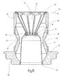
- This enveloping body is a double ball joint 41 and is formed from a seal holder 50, a Mitteilteil 52 and a ball socket 54.
- the seal holder 50 has a spherical recess 56 into which the middle part 52 is inserted.
- the middle part 52 in turn has for this purpose two ball inserts 60 and 62.
- the ball insert 60 is arranged in the spherical bulge 56 and movable in this. Proximal on the ball insert 62, the ball socket 54 is movably arranged with a spherical bulge 58 ( Fig. 10 and 11 ).
- This device forms the envelope body for an arrangement of expansion cone 20 and a seal 42 comparable to the sealing system 18 of Fig. 5 ,
- the seal 42 is fastened with a sealing edge 48 on the seal holder 50.
- the seal 42 has a socket 46, in which the terminations 34 of the slats 22 are arranged in a form-fitting manner.
- the seal 42 has an opening 44 at the proximal end and a sealing lip 45 between the opening 44 and the surrounding socket 46.
- the proximal end of the ball socket 54 is connected to the annular body 24 of the expansion cone 20.
- connection between the fins 22 and the socket 46 in such a movement of the expansion cone 20 for a corresponding deformation of the seal 48.
- the result is that the shaft despite the offset has a central position in the opening 44 of the seal 48 and no tilting in the opening 44 and no resulting leakage occurs. Due to the double ball joint 41, the sealing system thus adapts to any displacement of a shaft in the medical instrument.
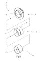
- FIG. 13 Another embodiment for slats is in Fig. 13 shown.
- a lamella 84 shown there has a termination 89 at the distal end and a ball head 86 at the proximal end.
- This ball head 86 serves for the movable connection of the lamella 84 with an annular body 82.
- the annular body 82 has openings 88 into which the ball heads 86 can be inserted.
- the insertion of the slats is conceivable both as a latching mechanism and as a simple insertion mechanism.
- a cover ring (not shown here) would then be necessary which prevents unintentional falling off of the lamellae 84 from the annular body 82 ( Fig. 12 ).
- a shaft 90 is inserted from the proximal end through the annular body 24 into the sealing system ( Fig. 14 ).
- this shaft 90 abuts with its distal end against the fins 22 of the expansion cone 20. Of these, it is guided in the direction of the arrow 92 in the direction of the opening 44 with continuous movement.
Landscapes
- Health & Medical Sciences (AREA)
- Surgery (AREA)
- Life Sciences & Earth Sciences (AREA)
- Biomedical Technology (AREA)
- Nuclear Medicine, Radiotherapy & Molecular Imaging (AREA)
- Engineering & Computer Science (AREA)
- Pathology (AREA)
- Heart & Thoracic Surgery (AREA)
- Medical Informatics (AREA)
- Molecular Biology (AREA)
- Animal Behavior & Ethology (AREA)
- General Health & Medical Sciences (AREA)
- Public Health (AREA)
- Veterinary Medicine (AREA)
- Surgical Instruments (AREA)
Applications Claiming Priority (1)
| Application Number | Priority Date | Filing Date | Title |
|---|---|---|---|
| DE102008035310A DE102008035310A1 (de) | 2008-07-23 | 2008-07-23 | Medizinisches Instrument mit einem flexiblen Dichtungssystem |
Publications (3)
| Publication Number | Publication Date |
|---|---|
| EP2147646A2 true EP2147646A2 (fr) | 2010-01-27 |
| EP2147646A3 EP2147646A3 (fr) | 2010-06-02 |
| EP2147646B1 EP2147646B1 (fr) | 2015-01-28 |
Family
ID=41227278
Family Applications (1)
| Application Number | Title | Priority Date | Filing Date |
|---|---|---|---|
| EP09166106.6A Not-in-force EP2147646B1 (fr) | 2008-07-23 | 2009-07-22 | Instrument médical doté d'un système d'étanchéité flexible |
Country Status (3)
| Country | Link |
|---|---|
| US (2) | US8475485B2 (fr) |
| EP (1) | EP2147646B1 (fr) |
| DE (1) | DE102008035310A1 (fr) |
Families Citing this family (9)
| Publication number | Priority date | Publication date | Assignee | Title |
|---|---|---|---|---|
| DE102008035311A1 (de) * | 2008-07-23 | 2010-01-28 | Karl Storz Gmbh & Co. Kg | Medizinisches Instrument mit seitlich versetzbarer Dichtung |
| WO2013167717A1 (fr) * | 2012-05-09 | 2013-11-14 | EON Surgical Ltd. | Orifice laparoscopique |
| CN102764150B (zh) * | 2012-06-27 | 2014-11-05 | 佛山特种医用导管有限责任公司 | 一种密封圈及具有该密封圈的穿刺套管 |
| USD724199S1 (en) * | 2012-08-30 | 2015-03-10 | Guided Therapeutics, Inc. | Medical diagnostic stand off tube |
| EP2900740B1 (fr) | 2012-09-28 | 2017-08-23 | Sophion Bioscience A/S | Procédé pour appliquer un revêtement sur un substrat polymère |
| CN106037898B (zh) * | 2016-08-02 | 2017-08-25 | 成都五义医疗科技有限公司 | 一种可整体内翻的穿刺器密封系统 |
| WO2018023149A1 (fr) * | 2016-08-04 | 2018-02-08 | Macquarie University | Guide de laparoscopie. |
| US10939937B2 (en) | 2017-06-29 | 2021-03-09 | Ethicon Llc | Trocar with oblique needle insertion port and perpendicular seal latch |
| US10639068B2 (en) | 2017-06-29 | 2020-05-05 | Ethicon Llc | Trocar with oblique needle insertion port and perpendicular seal latch |
Citations (1)
| Publication number | Priority date | Publication date | Assignee | Title |
|---|---|---|---|---|
| EP0696459B1 (fr) | 1994-08-08 | 1998-11-04 | United States Surgical Corporation | Système de vanne pour ensemble à canule |
Family Cites Families (6)
| Publication number | Priority date | Publication date | Assignee | Title |
|---|---|---|---|---|
| US5308336A (en) * | 1982-09-28 | 1994-05-03 | Applied Medical Resources | Seal protection mechanism |
| DE4306205C1 (de) * | 1993-02-27 | 1994-10-20 | Aesculap Ag | Trokarhülse zur Aufnahme eines chirurgischen Instruments |
| DE69624816T2 (de) * | 1995-06-08 | 2003-09-11 | Engineers & Doctors A/S, Kvistgaard | Katheter mit öffnungs und schliessmechanismus |
| US5628732A (en) | 1996-01-19 | 1997-05-13 | Ethicon Endo-Surgery, Inc. | Trocar with improved universal seal |
| US7789861B2 (en) * | 2006-04-18 | 2010-09-07 | Ethicon Endo-Surgery, Inc. | Pleated trocar seal |
| US7648519B2 (en) * | 2006-09-13 | 2010-01-19 | Cambridge Endoscopic Devices, Inc. | Surgical instrument |
-
2008
- 2008-07-23 DE DE102008035310A patent/DE102008035310A1/de not_active Withdrawn
-
2009
- 2009-07-22 US US12/507,476 patent/US8475485B2/en not_active Expired - Fee Related
- 2009-07-22 EP EP09166106.6A patent/EP2147646B1/fr not_active Not-in-force
-
2013
- 2013-06-03 US US13/908,685 patent/US8668711B2/en not_active Expired - Fee Related
Patent Citations (1)
| Publication number | Priority date | Publication date | Assignee | Title |
|---|---|---|---|---|
| EP0696459B1 (fr) | 1994-08-08 | 1998-11-04 | United States Surgical Corporation | Système de vanne pour ensemble à canule |
Also Published As
| Publication number | Publication date |
|---|---|
| EP2147646B1 (fr) | 2015-01-28 |
| US20130267900A1 (en) | 2013-10-10 |
| EP2147646A3 (fr) | 2010-06-02 |
| US20100049145A1 (en) | 2010-02-25 |
| US8668711B2 (en) | 2014-03-11 |
| US8475485B2 (en) | 2013-07-02 |
| DE102008035310A1 (de) | 2010-01-28 |
Similar Documents
| Publication | Publication Date | Title |
|---|---|---|
| EP2147646B1 (fr) | Instrument médical doté d'un système d'étanchéité flexible | |
| DE69323750T2 (de) | Ventil | |
| DE69204958T2 (de) | Universelle Abdichtung für Trokarbesteck. | |
| DE69827193T2 (de) | Arthroskopie-Kanüle mit Flüssigkeitsdichtungen | |
| EP2143393B1 (fr) | Dispositif de protection chirurgical pour un élément d'étanchéité chirurgical et système d'étanchéification chirurgical | |
| DE69818710T2 (de) | Universelle dichtung zur verwendung mit einer endoskopkanüle | |
| EP1350476B1 (fr) | Manchon de trocart | |
| DE69531908T2 (de) | Trokar mit einer Mehrzahl von Zugängen | |
| DE69521995T2 (de) | Trokarventileinheit | |
| DE69431883T2 (de) | Dichtung für alle durchmesserbereiche chirurgischer instrumente | |
| EP1998692B1 (fr) | Element chirgurgical d'etancheite, joint chirurgical et systeme chirurgical d'etancheite | |
| EP1977677B1 (fr) | Instrument endoscopique | |
| EP2604203B1 (fr) | Dispositif d'étanchéité pour étanchéifier un passage pour un instrument médical | |
| EP2143392B1 (fr) | Fixation d'élément étanche chirurgical pour maintenir un élément étanche chirurgical et système d'étanchéification chirurgical | |
| EP2103265A1 (fr) | Joint pour un trocart | |
| DE202008009527U1 (de) | Chirurgische Schutzvorrichtung für ein chirurgisches Dichtelement und chirurgisches Abdichtungssystem | |
| EP2241275A1 (fr) | Instrument médical destiné à créer un accès pour une intervention mini-invasive | |
| EP1852074B1 (fr) | Joint pour une gaine de trocart tout comme gaine de trocart de ce type | |
| EP2725962B1 (fr) | Système de trocart | |
| WO1999049794A1 (fr) | Instrument chirurgical muni d'un canal creux continu pour un autre instrument | |
| EP2147645B1 (fr) | Instrument médical doté d'un joint déplaçable latéralement | |
| EP1083834B1 (fr) | Dispositif permettant de pratiquer un acces transcutane a un organe interne creux | |
| WO1996008204A1 (fr) | Instrument chirurgical | |
| EP2762094A1 (fr) | Dispositif d'étanchéité pour étanchéifier un passage pour un instrument médical | |
| EP3518837B1 (fr) | Écarteur à assemblage de type puzzle |
Legal Events
| Date | Code | Title | Description |
|---|---|---|---|
| PUAI | Public reference made under article 153(3) epc to a published international application that has entered the european phase |
Free format text: ORIGINAL CODE: 0009012 |
|
| AK | Designated contracting states |
Kind code of ref document: A2 Designated state(s): AT BE BG CH CY CZ DE DK EE ES FI FR GB GR HR HU IE IS IT LI LT LU LV MC MK MT NL NO PL PT RO SE SI SK SM TR |
|
| AX | Request for extension of the european patent |
Extension state: AL BA RS |
|
| PUAL | Search report despatched |
Free format text: ORIGINAL CODE: 0009013 |
|
| AK | Designated contracting states |
Kind code of ref document: A3 Designated state(s): AT BE BG CH CY CZ DE DK EE ES FI FR GB GR HR HU IE IS IT LI LT LU LV MC MK MT NL NO PL PT RO SE SI SK SM TR |
|
| AX | Request for extension of the european patent |
Extension state: AL BA RS |
|
| 17P | Request for examination filed |
Effective date: 20101129 |
|
| GRAP | Despatch of communication of intention to grant a patent |
Free format text: ORIGINAL CODE: EPIDOSNIGR1 |
|
| INTG | Intention to grant announced |
Effective date: 20140912 |
|
| GRAS | Grant fee paid |
Free format text: ORIGINAL CODE: EPIDOSNIGR3 |
|
| GRAA | (expected) grant |
Free format text: ORIGINAL CODE: 0009210 |
|
| AK | Designated contracting states |
Kind code of ref document: B1 Designated state(s): AT BE BG CH CY CZ DE DK EE ES FI FR GB GR HR HU IE IS IT LI LT LU LV MC MK MT NL NO PL PT RO SE SI SK SM TR |
|
| REG | Reference to a national code |
Ref country code: GB Ref legal event code: FG4D Free format text: NOT ENGLISH |
|
| REG | Reference to a national code |
Ref country code: CH Ref legal event code: EP |
|
| REG | Reference to a national code |
Ref country code: IE Ref legal event code: FG4D Free format text: LANGUAGE OF EP DOCUMENT: GERMAN |
|
| REG | Reference to a national code |
Ref country code: DE Ref legal event code: R096 Ref document number: 502009010560 Country of ref document: DE Effective date: 20150312 |
|
| REG | Reference to a national code |
Ref country code: AT Ref legal event code: REF Ref document number: 707891 Country of ref document: AT Kind code of ref document: T Effective date: 20150315 |
|
| REG | Reference to a national code |
Ref country code: NL Ref legal event code: VDEP Effective date: 20150128 |
|
| REG | Reference to a national code |
Ref country code: LT Ref legal event code: MG4D |
|
| PG25 | Lapsed in a contracting state [announced via postgrant information from national office to epo] |
Ref country code: NO Free format text: LAPSE BECAUSE OF FAILURE TO SUBMIT A TRANSLATION OF THE DESCRIPTION OR TO PAY THE FEE WITHIN THE PRESCRIBED TIME-LIMIT Effective date: 20150428 Ref country code: HR Free format text: LAPSE BECAUSE OF FAILURE TO SUBMIT A TRANSLATION OF THE DESCRIPTION OR TO PAY THE FEE WITHIN THE PRESCRIBED TIME-LIMIT Effective date: 20150128 Ref country code: ES Free format text: LAPSE BECAUSE OF FAILURE TO SUBMIT A TRANSLATION OF THE DESCRIPTION OR TO PAY THE FEE WITHIN THE PRESCRIBED TIME-LIMIT Effective date: 20150128 Ref country code: BG Free format text: LAPSE BECAUSE OF FAILURE TO SUBMIT A TRANSLATION OF THE DESCRIPTION OR TO PAY THE FEE WITHIN THE PRESCRIBED TIME-LIMIT Effective date: 20150428 Ref country code: SE Free format text: LAPSE BECAUSE OF FAILURE TO SUBMIT A TRANSLATION OF THE DESCRIPTION OR TO PAY THE FEE WITHIN THE PRESCRIBED TIME-LIMIT Effective date: 20150128 Ref country code: LT Free format text: LAPSE BECAUSE OF FAILURE TO SUBMIT A TRANSLATION OF THE DESCRIPTION OR TO PAY THE FEE WITHIN THE PRESCRIBED TIME-LIMIT Effective date: 20150128 Ref country code: FI Free format text: LAPSE BECAUSE OF FAILURE TO SUBMIT A TRANSLATION OF THE DESCRIPTION OR TO PAY THE FEE WITHIN THE PRESCRIBED TIME-LIMIT Effective date: 20150128 |
|
| PG25 | Lapsed in a contracting state [announced via postgrant information from national office to epo] |
Ref country code: LV Free format text: LAPSE BECAUSE OF FAILURE TO SUBMIT A TRANSLATION OF THE DESCRIPTION OR TO PAY THE FEE WITHIN THE PRESCRIBED TIME-LIMIT Effective date: 20150128 Ref country code: NL Free format text: LAPSE BECAUSE OF FAILURE TO SUBMIT A TRANSLATION OF THE DESCRIPTION OR TO PAY THE FEE WITHIN THE PRESCRIBED TIME-LIMIT Effective date: 20150128 Ref country code: GR Free format text: LAPSE BECAUSE OF FAILURE TO SUBMIT A TRANSLATION OF THE DESCRIPTION OR TO PAY THE FEE WITHIN THE PRESCRIBED TIME-LIMIT Effective date: 20150429 Ref country code: IS Free format text: LAPSE BECAUSE OF FAILURE TO SUBMIT A TRANSLATION OF THE DESCRIPTION OR TO PAY THE FEE WITHIN THE PRESCRIBED TIME-LIMIT Effective date: 20150528 Ref country code: PL Free format text: LAPSE BECAUSE OF FAILURE TO SUBMIT A TRANSLATION OF THE DESCRIPTION OR TO PAY THE FEE WITHIN THE PRESCRIBED TIME-LIMIT Effective date: 20150128 |
|
| REG | Reference to a national code |
Ref country code: DE Ref legal event code: R097 Ref document number: 502009010560 Country of ref document: DE |
|
| PG25 | Lapsed in a contracting state [announced via postgrant information from national office to epo] |
Ref country code: CZ Free format text: LAPSE BECAUSE OF FAILURE TO SUBMIT A TRANSLATION OF THE DESCRIPTION OR TO PAY THE FEE WITHIN THE PRESCRIBED TIME-LIMIT Effective date: 20150128 Ref country code: RO Free format text: LAPSE BECAUSE OF FAILURE TO SUBMIT A TRANSLATION OF THE DESCRIPTION OR TO PAY THE FEE WITHIN THE PRESCRIBED TIME-LIMIT Effective date: 20150128 Ref country code: EE Free format text: LAPSE BECAUSE OF FAILURE TO SUBMIT A TRANSLATION OF THE DESCRIPTION OR TO PAY THE FEE WITHIN THE PRESCRIBED TIME-LIMIT Effective date: 20150128 Ref country code: DK Free format text: LAPSE BECAUSE OF FAILURE TO SUBMIT A TRANSLATION OF THE DESCRIPTION OR TO PAY THE FEE WITHIN THE PRESCRIBED TIME-LIMIT Effective date: 20150128 Ref country code: SK Free format text: LAPSE BECAUSE OF FAILURE TO SUBMIT A TRANSLATION OF THE DESCRIPTION OR TO PAY THE FEE WITHIN THE PRESCRIBED TIME-LIMIT Effective date: 20150128 |
|
| PLBE | No opposition filed within time limit |
Free format text: ORIGINAL CODE: 0009261 |
|
| STAA | Information on the status of an ep patent application or granted ep patent |
Free format text: STATUS: NO OPPOSITION FILED WITHIN TIME LIMIT |
|
| 26N | No opposition filed |
Effective date: 20151029 |
|
| PG25 | Lapsed in a contracting state [announced via postgrant information from national office to epo] |
Ref country code: SI Free format text: LAPSE BECAUSE OF FAILURE TO SUBMIT A TRANSLATION OF THE DESCRIPTION OR TO PAY THE FEE WITHIN THE PRESCRIBED TIME-LIMIT Effective date: 20150128 Ref country code: MC Free format text: LAPSE BECAUSE OF FAILURE TO SUBMIT A TRANSLATION OF THE DESCRIPTION OR TO PAY THE FEE WITHIN THE PRESCRIBED TIME-LIMIT Effective date: 20150128 |
|
| REG | Reference to a national code |
Ref country code: CH Ref legal event code: PL |
|
| PG25 | Lapsed in a contracting state [announced via postgrant information from national office to epo] |
Ref country code: LU Free format text: LAPSE BECAUSE OF FAILURE TO SUBMIT A TRANSLATION OF THE DESCRIPTION OR TO PAY THE FEE WITHIN THE PRESCRIBED TIME-LIMIT Effective date: 20150722 |
|
| REG | Reference to a national code |
Ref country code: IE Ref legal event code: MM4A |
|
| PG25 | Lapsed in a contracting state [announced via postgrant information from national office to epo] |
Ref country code: LI Free format text: LAPSE BECAUSE OF NON-PAYMENT OF DUE FEES Effective date: 20150731 Ref country code: CH Free format text: LAPSE BECAUSE OF NON-PAYMENT OF DUE FEES Effective date: 20150731 |
|
| REG | Reference to a national code |
Ref country code: FR Ref legal event code: PLFP Year of fee payment: 8 |
|
| PG25 | Lapsed in a contracting state [announced via postgrant information from national office to epo] |
Ref country code: IE Free format text: LAPSE BECAUSE OF NON-PAYMENT OF DUE FEES Effective date: 20150722 |
|
| PGFP | Annual fee paid to national office [announced via postgrant information from national office to epo] |
Ref country code: GB Payment date: 20160627 Year of fee payment: 8 |
|
| PGFP | Annual fee paid to national office [announced via postgrant information from national office to epo] |
Ref country code: FR Payment date: 20160622 Year of fee payment: 8 |
|
| REG | Reference to a national code |
Ref country code: AT Ref legal event code: MM01 Ref document number: 707891 Country of ref document: AT Kind code of ref document: T Effective date: 20150722 |
|
| PGFP | Annual fee paid to national office [announced via postgrant information from national office to epo] |
Ref country code: IT Payment date: 20160627 Year of fee payment: 8 |
|
| PG25 | Lapsed in a contracting state [announced via postgrant information from national office to epo] |
Ref country code: AT Free format text: LAPSE BECAUSE OF NON-PAYMENT OF DUE FEES Effective date: 20150722 |
|
| PG25 | Lapsed in a contracting state [announced via postgrant information from national office to epo] |
Ref country code: MT Free format text: LAPSE BECAUSE OF FAILURE TO SUBMIT A TRANSLATION OF THE DESCRIPTION OR TO PAY THE FEE WITHIN THE PRESCRIBED TIME-LIMIT Effective date: 20150128 |
|
| PG25 | Lapsed in a contracting state [announced via postgrant information from national office to epo] |
Ref country code: SM Free format text: LAPSE BECAUSE OF FAILURE TO SUBMIT A TRANSLATION OF THE DESCRIPTION OR TO PAY THE FEE WITHIN THE PRESCRIBED TIME-LIMIT Effective date: 20150128 Ref country code: HU Free format text: LAPSE BECAUSE OF FAILURE TO SUBMIT A TRANSLATION OF THE DESCRIPTION OR TO PAY THE FEE WITHIN THE PRESCRIBED TIME-LIMIT; INVALID AB INITIO Effective date: 20090722 |
|
| PG25 | Lapsed in a contracting state [announced via postgrant information from national office to epo] |
Ref country code: CY Free format text: LAPSE BECAUSE OF FAILURE TO SUBMIT A TRANSLATION OF THE DESCRIPTION OR TO PAY THE FEE WITHIN THE PRESCRIBED TIME-LIMIT Effective date: 20150128 |
|
| PG25 | Lapsed in a contracting state [announced via postgrant information from national office to epo] |
Ref country code: BE Free format text: LAPSE BECAUSE OF NON-PAYMENT OF DUE FEES Effective date: 20150731 |
|
| PG25 | Lapsed in a contracting state [announced via postgrant information from national office to epo] |
Ref country code: TR Free format text: LAPSE BECAUSE OF FAILURE TO SUBMIT A TRANSLATION OF THE DESCRIPTION OR TO PAY THE FEE WITHIN THE PRESCRIBED TIME-LIMIT Effective date: 20150128 |
|
| REG | Reference to a national code |
Ref country code: DE Ref legal event code: R081 Ref document number: 502009010560 Country of ref document: DE Owner name: KARL STORZ SE & CO. KG INTELLECTUAL PROPERTY, DE Free format text: FORMER OWNER: KARL STORZ GMBH & CO. KG, 78532 TUTTLINGEN, DE Ref country code: DE Ref legal event code: R082 Ref document number: 502009010560 Country of ref document: DE Representative=s name: WITTE, WELLER & PARTNER PATENTANWAELTE MBB, DE Ref country code: DE Ref legal event code: R081 Ref document number: 502009010560 Country of ref document: DE Owner name: KARL STORZ SE & CO. KG, DE Free format text: FORMER OWNER: KARL STORZ GMBH & CO. KG, 78532 TUTTLINGEN, DE |
|
| GBPC | Gb: european patent ceased through non-payment of renewal fee |
Effective date: 20170722 |
|
| REG | Reference to a national code |
Ref country code: FR Ref legal event code: ST Effective date: 20180330 |
|
| PG25 | Lapsed in a contracting state [announced via postgrant information from national office to epo] |
Ref country code: GB Free format text: LAPSE BECAUSE OF NON-PAYMENT OF DUE FEES Effective date: 20170722 |
|
| PG25 | Lapsed in a contracting state [announced via postgrant information from national office to epo] |
Ref country code: FR Free format text: LAPSE BECAUSE OF NON-PAYMENT OF DUE FEES Effective date: 20170731 |
|
| PG25 | Lapsed in a contracting state [announced via postgrant information from national office to epo] |
Ref country code: MK Free format text: LAPSE BECAUSE OF FAILURE TO SUBMIT A TRANSLATION OF THE DESCRIPTION OR TO PAY THE FEE WITHIN THE PRESCRIBED TIME-LIMIT Effective date: 20150128 Ref country code: PT Free format text: LAPSE BECAUSE OF FAILURE TO SUBMIT A TRANSLATION OF THE DESCRIPTION OR TO PAY THE FEE WITHIN THE PRESCRIBED TIME-LIMIT Effective date: 20150128 |
|
| PG25 | Lapsed in a contracting state [announced via postgrant information from national office to epo] |
Ref country code: IT Free format text: LAPSE BECAUSE OF NON-PAYMENT OF DUE FEES Effective date: 20170722 |
|
| P01 | Opt-out of the competence of the unified patent court (upc) registered |
Effective date: 20230527 |
|
| PGFP | Annual fee paid to national office [announced via postgrant information from national office to epo] |
Ref country code: DE Payment date: 20240730 Year of fee payment: 16 |
|
| REG | Reference to a national code |
Ref country code: DE Ref legal event code: R119 Ref document number: 502009010560 Country of ref document: DE |
|
| PG25 | Lapsed in a contracting state [announced via postgrant information from national office to epo] |
Ref country code: DE Free format text: LAPSE BECAUSE OF NON-PAYMENT OF DUE FEES Effective date: 20260203 |