EP2147641A1 - Staple for use in surgical procedures - Google Patents
Staple for use in surgical procedures Download PDFInfo
- Publication number
- EP2147641A1 EP2147641A1 EP09251793A EP09251793A EP2147641A1 EP 2147641 A1 EP2147641 A1 EP 2147641A1 EP 09251793 A EP09251793 A EP 09251793A EP 09251793 A EP09251793 A EP 09251793A EP 2147641 A1 EP2147641 A1 EP 2147641A1
- Authority
- EP
- European Patent Office
- Prior art keywords
- staple
- backspan
- leg
- tissue
- clenching
- Prior art date
- Legal status (The legal status is an assumption and is not a legal conclusion. Google has not performed a legal analysis and makes no representation as to the accuracy of the status listed.)
- Granted
Links
- 238000001356 surgical procedure Methods 0.000 title description 3
- 230000015572 biosynthetic process Effects 0.000 description 13
- 239000000463 material Substances 0.000 description 10
- 238000000034 method Methods 0.000 description 8
- 230000000149 penetrating effect Effects 0.000 description 7
- 230000006835 compression Effects 0.000 description 3
- 238000007906 compression Methods 0.000 description 3
- 230000003116 impacting effect Effects 0.000 description 3
- RTAQQCXQSZGOHL-UHFFFAOYSA-N Titanium Chemical compound [Ti] RTAQQCXQSZGOHL-UHFFFAOYSA-N 0.000 description 2
- 230000006870 function Effects 0.000 description 2
- 239000007769 metal material Substances 0.000 description 2
- 238000012986 modification Methods 0.000 description 2
- 230000004048 modification Effects 0.000 description 2
- 238000004513 sizing Methods 0.000 description 2
- 239000010935 stainless steel Substances 0.000 description 2
- 229910001220 stainless steel Inorganic materials 0.000 description 2
- 229910052719 titanium Inorganic materials 0.000 description 2
- 239000010936 titanium Substances 0.000 description 2
- 230000007704 transition Effects 0.000 description 2
- 230000003466 anti-cipated effect Effects 0.000 description 1
- 239000000560 biocompatible material Substances 0.000 description 1
- 238000002788 crimping Methods 0.000 description 1
- -1 for example Substances 0.000 description 1
- 238000001746 injection moulding Methods 0.000 description 1
- 230000035515 penetration Effects 0.000 description 1
- 229910001285 shape-memory alloy Inorganic materials 0.000 description 1
Images




Classifications
-
- A—HUMAN NECESSITIES
- A61—MEDICAL OR VETERINARY SCIENCE; HYGIENE
- A61B—DIAGNOSIS; SURGERY; IDENTIFICATION
- A61B17/00—Surgical instruments, devices or methods
- A61B17/064—Surgical staples, i.e. penetrating the tissue
- A61B17/0644—Surgical staples, i.e. penetrating the tissue penetrating the tissue, deformable to closed position
-
- A—HUMAN NECESSITIES
- A61—MEDICAL OR VETERINARY SCIENCE; HYGIENE
- A61B—DIAGNOSIS; SURGERY; IDENTIFICATION
- A61B17/00—Surgical instruments, devices or methods
- A61B17/064—Surgical staples, i.e. penetrating the tissue
- A61B17/0643—Surgical staples, i.e. penetrating the tissue with separate closing member, e.g. for interlocking with staple
-
- A—HUMAN NECESSITIES
- A61—MEDICAL OR VETERINARY SCIENCE; HYGIENE
- A61B—DIAGNOSIS; SURGERY; IDENTIFICATION
- A61B17/00—Surgical instruments, devices or methods
- A61B2017/00831—Material properties
- A61B2017/00867—Material properties shape memory effect
-
- A—HUMAN NECESSITIES
- A61—MEDICAL OR VETERINARY SCIENCE; HYGIENE
- A61B—DIAGNOSIS; SURGERY; IDENTIFICATION
- A61B17/00—Surgical instruments, devices or methods
- A61B17/04—Surgical instruments, devices or methods for suturing wounds; Holders or packages for needles or suture materials
- A61B17/0401—Suture anchors, buttons or pledgets, i.e. means for attaching sutures to bone, cartilage or soft tissue; Instruments for applying or removing suture anchors
- A61B2017/0406—Pledgets
Definitions
- the present disclosure relates to a surgical staple for use in surgical procedures. More particularly, the present disclosure relates to a surgical staple and a staple assembly configured to accommodate various thicknesses of tissue by assuming a substantially box-shaped configuration upon formation through tissue. The present disclosure also relates to a method of stapling tissues of various thicknesses with a single, uniform size staple.
- auxiliary structures such as, for example, mesh, buttress material, etc.
- tissue sections During various surgical procedures it is often necessary to secure one or more tissue sections together or to secure auxiliary structures such as, for example, mesh, buttress material, etc. to tissue.
- This is typically accomplished by driving a conventional staple, having a backspan and a pair of legs extending from the backspan, through the tissue and/or through the auxiliary structure.
- the conventional staple Once the conventional staple has been driven through the tissue, the ends of the legs are engaged with an anvil of the type typically having a pair of arcuate anvil pockets. This engagement causes the ends of the legs to be bent or recurved back towards the tissue to secure the tissue sections together and/or to secure the auxiliary material to the tissue.
- These bent or recurved portions of the staple legs are the tissue clenching portions of the legs.
- the sizing of the conventional staple is selected to ensure sufficient leg lengths to traverse the tissue. Insufficient leg lengths will result in incomplete stapling of the tissue.
- the sizing of the conventional staple is selected to ensure that there is not an excess of leg length. Excess leg length may result in the clenching portions of the legs projecting substantially away from the tissue as well as causing the ends of the leg to recurve back into and penetrate the tissue.
- the first leg is divided into a first traversing leg portion and a first substantially linear clenching leg portion by a first bend.
- a second leg extends from the backspan and is divided into a second traversing leg portion and a second substantially linear clenching leg portion by a second bend.
- At least one of the first and second substantially linear clenching leg portions is oriented substantially parallel to the backspan. In one embodiment, both the first and second substantially linear clenching leg portions are oriented substantially parallel to the backspan.
- At least one of the first and second traversing leg portions is oriented substantially perpendicular to the backspan. In one embodiment, both the first and second traversing leg portions are oriented substantially perpendicular to the backspan.
- a combined length of the first and second clenching leg portions is less than an overall length of the backspan. In an alternative embodiment, the combined length of the first and second clenching leg portions is equal to an overall length of the backspan. In another alternative embodiment, the combined length of the first and second clenching leg portions is greater than an overall length of the backspan.
- a staple assembly for use in tissue which generally includes a substantially box-shaped staple having a backspan and first and second legs extending from the backspan.
- the first leg is divided into a first traversing leg portion and a first substantially linear clenching leg portion by a first bend.
- the second leg is also divided into a second traversing leg portion and a second substantially linear clenching leg portion by a second bend.
- a staple plate is positioned on the first and second legs between the backspan and the first and second linear clenching leg portions. At least one of the first and second substantially linear clenching leg portions is oriented substantially parallel to the staple plate.
- the staple plate preferably has first and second holes to receive the first and second traversing leg portions, respectively.
- an overall length of the staple plate is greater than an overall length of the backspan and the distance between the first and second holes is substantially equal to the overall length of the backspan.
- a method of forming a substantially box-shaped staple through tissue including the step of providing a substantially box-shaped staple having a backspan, a first leg extending from the backspan and including a first bend zone located between the backspan and a first end of the first leg, and a second leg extending from the backspan and including a second bend zone located between the backspan and a second end of the second leg.
- the first and second ends of the first and second legs are driven through a tissue section.
- the first leg is impacted in the first bend zone with a first angled portion of a first anvil to form a first bend within the first bend zone to form a first traversing leg portion and a first substantially linear clenching leg portion.
- the method may further include the step of impacting the first clenching leg portion with a first finishing surface of the first anvil to orient the first clenching leg portion substantially parallel to the backspan.
- the method may further include the step of impacting the second leg in the second bend zone with a second angled portion of a second anvil to form a second bend within the second bend zone and dividing the second bend zone into a second traversing leg portion and a second substantially linear clenching leg portion.
- the second clenching leg portion may be impacted with a second finishing surface of the second anvil to orient the second clenching leg portion substantially parallel to the backspan.
- the first and second ends are driven through tissue such that the backspan engages an upper surface of the tissue.
- a staple plate is positioned over the first and second legs and engages an underside of the tissue prior to the step of impacting the first leg in the first bend zone.
- a universal staple 10 for use in various thickness of tissues.
- Staple 10 is substantially box-shaped and has the further advantage of providing uniform pressure against the underside of the tissues stapled as described in more detail hereinbelow.
- Substantially box-shaped staple 10 generally includes a backspan 12 and first and second legs 14 and 16, respectively, extending from backspan 12. Specifically, a first end 18 of first leg 14 extends downwardly (as viewed in Fig.1 ) from a first end 20 of backspan 12 and a second end 22 of second leg 16 extends downwardly from a second end 24 of backspan 12.
- First leg 14 terminates in a tissue penetrating tip 26 and second leg 16 terminates in a tissue penetrating tip 28.
- the legs 14 and 16 are shown extending substantially perpendicular to the backspan, although it is also contemplated that the legs 14, 16 can extend from other angles.
- Substantially box staple 10 is preferably formed from a length of material having a generally rectangular cross-section, although other cross sections are also contemplated.
- Staple 10 can be formed from any number of biocompatible materials such as, for example, stainless steel, titanium, various malleable plastic materials, various bio-absorbable materials etc.
- staple 10 can be formed by drawing and cutting a length of metallic wire, stamping box staple 10 from a sheet of metallic material, etc.
- staple 10 can be formed by injection molding, carving staple 10 from a block of plastic material, etc.
- first leg 14 has a first bend zone 30 which extends substantially between first end 18 and tissue penetrating tip 26 of first leg 14.
- first leg 14 can be bent at any location within bend zone 30 to accommodate those tissues. This is facilitated by the use of a pair of anvils as described in more detail herein below.
- Second leg 16 also includes a second bend zone 32 which extends substantially between second end 22 and tissue penetrating tip 28 of second leg 16 and can be bent at any location within bend zone 32.
- first leg 14 is formed with a first bend 34 in first transition zone 30 such that first leg 14 is divided into a first, substantially linear traversing leg portion 36 extending through relatively thick tissues A and B ( FIG. 1 ) and a first substantially linear clenching leg portion 38 lying substantially flush with an underside D of relatively thick tissue section B ( FIGS.1 and 4 ).
- first bend 34 formed between first traversing leg portion 36 and first clenching leg portion 38 is preferably a substantially sharp or abrupt 90° bend in contrast to the relatively gradually curving bends typically associated with prior art staples.
- second leg 16 is formed with a second bend 40 in second bend zone 32 which divides second leg 16 into a second substantially linear traversing leg portion 42 extending through relatively thick tissue sections A and B ( FIGS. 1 and 2 ) and a second substantially linear clenching leg portion 44 lying substantially flush with underside D of relatively thick tissue section B. ( FIGS. 1 and 4 ).
- Second bend 40 also preferably forms a relatively sharp or abrupt 90° transition between second traversing leg portion 42 and second clenching like portion 44.
- first and second clenching leg portions 38 and 44 By maintaining first and second clenching leg portions 38 and 44 in a relatively linear or straight configuration against underside D of relatively thick tissue section B, first clenching leg portion 38 and second clenching leg portion 44 maintain a uniform compression against underside D without the associated pinching or tip penetration of underside D.
- the length L1 of backspan 12 is preferably greater than or equal to the combined lengths L2 and L3 of first and second linear clenching leg portions 38 and 44, respectively.
- staple 10 With relatively thick tissue sections A and B will now be described.
- the dimensions of staple 10 are preferably chosen such that legs 14 and 16 have overall lengths L4 and L5 which are substantially greater than the anticipated combined thicknesses of any tissues to be encountered.
- each of the overall lengths L4 and L5 of first and second legs 14 and 16, respectively is preferably greater than half the overall length L1 of backspan 12. This ensures sufficient leg length to traverse and secure both relatively thick and thin tissue sections.
- Staple 10 is initially driven through relatively thick tissue sections A and B by engaging backspan 12 with a staple driver (not shown) thereby driving first and second tissue penetrating tips 26 and 28, respectively, through tissue sections A and B.
- First and second driven anvils 50 and 52 are driven laterally against first and second staple legs 14 and 16 to form staple 10 through relatively thick tissue sections A and B.
- First and second driven anvils 50 and 52 generally include respective first and second angled surfaces 54 and 56 and respective first and second finishing surfaces 58 and 60.
- First and second angled surfaces 54 and 56 are provided to initially impact or impinge against first and second legs 14 and 16 within the respective first and second bend zones 30 and 32 to initially create first and second bends 34 and 40. This divides first bend zone 30 of first leg 14 into first traversing leg portion 36 and first linear clenching leg portion 38. Similarly, this divides second bend zone 32 into second traversing leg portion 42 and second linear clenching leg portion 44.
- first and second linear clenching leg portions 38 and 44 are engaged by relatively linear finishing surfaces 58 and 60 of driven anvils 50 and 52, respectively, such that first and second linear clenching leg portions 38 and 44 are brought substantially flush into engagement with underside D of relatively thick tissue section B.
- first and second linear clenching leg portions 38 and 44 are substantially less than or equal to the overall length L1 of backspan 12.
- substantially box staple 10 is illustrated in the configuration it assumes when used through a pair of relatively thin tissue sections. Specifically, when staple 10 is formed through relatively thin tissue sections, each of the lengths L2 and L3 of respective first and second linear clenching leg portions 38 and 44 are almost equal to or greater than the overall length L1 of backspan 12.
- first and second traversing leg portions 36 and 42 pass through thin tissue sections E and F.
- First and second linear clenching leg portions 38 and 44 preferably lie substantially parallel to and substantially flush with tissue section F.
- backspan 12 engages an upper surface G of tissue section E while first and second linear clenching leg portions 38 and 44 engage an underside surface H of tissue G.
- staple 10 functions as a universal staple suitable for use with both thick and thin tissue sections without risk of penetrating the tissue sections with first and second tissue penetrating tips 26 and 28 of respective first and second legs 14 and 16.
- staple 10 is initially driven through tissue sections E and F. Thereafter, driven anvils 50 and 52 impact staple legs 14 and 16 to initially begin to bend staple legs 14 and 16. As shown in Figure 14 , angled faces 54 and 56 of driven staples 50 and 52 initially form bends 34 and 40 to create respective first and second traversing leg portions 36 and 42 and first and second linear clenching leg portions 38 and 44. Thereafter, with reference to FIG. 15 , finishing surfaces 58 and 60 of driven anvils 50 and 52 engage first and second linear clenching leg portions 38 and 44 to form first and second linear clenching leg portions 38 and 44 against underside H of tissue F and, substantially parallel to backspan 12.
- staple 10 is particularly suited for use with relatively thin tissue sections such that first and second linear clenching leg portions 38 and 44 lie substantially flush against the tissue to be stapled.
- FIGS. 16-20 and initially with regard to FIG. 16 there is disclosed an alternate embodiment having a staple assembly 70 including a substantially box-shaped staple 10 and a pledget or staple plate 72.
- Staple plate 72 increases the surface area engaging a tissue being stapled as well as protecting the tissue from engagement with staple legs 14 and 16 upon crimping of staple 10 about tissue.
- Staple 10 is as described herein above including backspan 12 and legs 14 and 16 extending from backspan 12.
- Staple plate 72 is substantially rectangular as shown (although other shapes are also contemplated) having first and second holes 74 and 76 adjacent first and second ends 78 and 80, respectively. First and second holes 74 and 76 are configured and dimensioned to receive first and second legs 14 and 16 of staple 10 therethrough. Staple plate 72 has an overall length L7 which is preferably greater than the length L1 of backspan 12 ( FIG. 1 ). Additionally, the spacing or length L6 between holes 74 and 76 is preferably substantially identical to the length L1 of backspan 12 as the legs 14 and 16 are preferably substantially perpendicular thereto. Other lengths are also contemplated.
- staple assembly 70 is provided to secure a pair of tissue sections, such as, for example, tissue sections I and J.
- Backspan 12 engages an upper surface K of tissue section I ( FIG. 19 ) while an upper surface 82 of staple plate 72 engages a lower surface L of tissue section J ( FIG. 20 ).
- staple plate 72 protects tissue section J from engagement with first and second clenching leg portions 38 and 44 of first and second legs 14 and 16, respectively. Specifically, upon formation of staple 10 through tissue sections I and J, staple plate 72 is interposed between tissue section J and first and second clenching leg portions 38 and 44.
- staple 10 is driven by a staple driver (not shown) toward tissue sections I and J such that first and second legs 14 and 16 penetrate tissue sections I and J until backspan 12 engages upper surface K of tissue section I.
- Staple plate 72 is positioned against undersurface K of tissue section J and legs 14 and 16 are extended through holes 74 and 76 of staple plate 72. This brings upper surface 82 of staple plate 72 into engagement with undersurface K of tissue section J.
- first and second driven anvils 50 and 52 are moved inwardly toward first and second legs 14 and 16.
- first and second legs 14 and 16 are initially bent within respective bend zones 30 and 32 to form first and second bends 34 and 40 within first and second legs 14 and 16.
- first bend 34 divides first leg 14 into first traversing leg portion 36 and first linear clenching leg portion 38
- second bend 40 divides second leg 16 into second traversing leg portion 42 and second linear clenching leg portion 44.
- the extension of first and second legs 14 and 16 through first and second holes 74 and 76 in staple plate 72 facilitate forming bends 74 and 76 at substantially right angles relative to first and second traversing leg portions 36 and 38 of first and second legs 14 and 16, respectively.
- first and second finishing surfaces 58 and 60 of the first and second driven anvils 50 and 52 with first and second linear clenching leg portions 38 and 44 serve to secure first and second linear clenching leg portions 38 and 44 against underside 84 of staple plate 72 thereby securing staple plate 84 against underside L of tissue section J.
- staple 10 is driven by a staple driver (not shown) such that first and second legs 14 and 16 are driven through tissue sections M and N until backspan 12 engages an upper surface O of tissue section M ( FIG. 25 ). Further movement of the staple driver drives first and second legs 14 and 16 through holes 74 and 76 of staple plate 72. Thereafter, first and second driven anvils 50 and 52 ( FIGS. 21-23 ) are moved toward each other as described above to form first and second linear clenching leg portions 38 and 44 against underside 84 of staple plate 72 ( FIG. 26 ).
- first and second linear clenching leg portions 38 and 44 are in a side-by-side and overlapping relation with respect to each other due to the excess lengths of legs 14 and 16 when used through relatively thin tissue sections M and N.
- the provision of substantially box staple 10 having first and second legs 14 and 16 with overall lengths almost equal to or greater then at least the overall length of backspan 12 allows staple 10 to function as a universal staple suitable for use with various thicknesses of tissue.
- the provision of staple plate 72 provides additional surface bearing area against the tissue section while facilitating forming an abrupt 90° bend within first and second legs 14 and 16.
- staple plate 72 may be formed of a material which allows staple plate 72 to be used with a staple 90 similar to staple 10 in situations wherein staple 90 is formed with conventional anvils.
- conventional anvils refers to those anvils having arcuate anvil pockets resulting in arcuate rather than linear clenching leg portions in the formed staple.
- staple 90 includes a backspan 92 having first and second legs 94 and 96 extending from backspan 92.
- staple 90 is driven through relatively thick tissue sections Q and R resulting in first and second traversing leg portions 98 and 100 extending through tissue sections Q and R while backspan 92 engages an upper surface S of tissue section Q.
- First and second legs 94 and 96 are extended through holes 74 and 76 in staple plate 72 and are clenched against staple plate 72 by arcuate anvil pockets formed in an anvil associated with a conventional stapler (not shown).
- first and second clenching leg portions 102 and 104 of first and second legs 94 and 96 are formed into a roughly arcuate overlapping relation due to the excess length of legs 94 and 96.
- staple plate 104 is preferably curved, thereby an arcuate top surface of the plate abuts the bottom surface of the tissue section R or V.
- the legs of the disclosed substantially box staple may be heat treated at specific points to facilitate the formation of the abrupt 90° bend between the traversing portion of the leg and the linear clenching portion of the leg.
- alternative embodiments of anvils may be provided to form the substantially right angle within their respective legs.
- the disclosed staple may be formed from a shape memory alloy such that the substantially right angle between the traversing leg portion and the substantially linear clenching leg portion is formed at a predetermined location along the length of the leg.
- curved or planar plates can be used with the embodiments of the staple disclosed herein. Therefore, the above description should not be construed as limiting, but merely as exemplifications of particular embodiments. Those skilled in the art will envision other modifications within the scope and spirit of the claims appended hereto.
Landscapes
- Health & Medical Sciences (AREA)
- Life Sciences & Earth Sciences (AREA)
- Surgery (AREA)
- Heart & Thoracic Surgery (AREA)
- Engineering & Computer Science (AREA)
- Biomedical Technology (AREA)
- Nuclear Medicine, Radiotherapy & Molecular Imaging (AREA)
- Medical Informatics (AREA)
- Molecular Biology (AREA)
- Animal Behavior & Ethology (AREA)
- General Health & Medical Sciences (AREA)
- Public Health (AREA)
- Veterinary Medicine (AREA)
- Surgical Instruments (AREA)
- Dental Tools And Instruments Or Auxiliary Dental Instruments (AREA)
Abstract
Description
- This application claims priority to provisional application no.
61/082,852, file July 23, 2008 - The present disclosure relates to a surgical staple for use in surgical procedures. More particularly, the present disclosure relates to a surgical staple and a staple assembly configured to accommodate various thicknesses of tissue by assuming a substantially box-shaped configuration upon formation through tissue. The present disclosure also relates to a method of stapling tissues of various thicknesses with a single, uniform size staple.
- During various surgical procedures it is often necessary to secure one or more tissue sections together or to secure auxiliary structures such as, for example, mesh, buttress material, etc. to tissue. This is typically accomplished by driving a conventional staple, having a backspan and a pair of legs extending from the backspan, through the tissue and/or through the auxiliary structure. Once the conventional staple has been driven through the tissue, the ends of the legs are engaged with an anvil of the type typically having a pair of arcuate anvil pockets. This engagement causes the ends of the legs to be bent or recurved back towards the tissue to secure the tissue sections together and/or to secure the auxiliary material to the tissue. These bent or recurved portions of the staple legs are the tissue clenching portions of the legs.
- When attempting to secure relatively thick sections of tissue together or auxiliary material to a relatively thick tissue section, the sizing of the conventional staple is selected to ensure sufficient leg lengths to traverse the tissue. Insufficient leg lengths will result in incomplete stapling of the tissue.
- Further, when attempting to secure relatively thin sections of tissue together, or auxiliary material to the relatively thin tissue section, the sizing of the conventional staple is selected to ensure that there is not an excess of leg length. Excess leg length may result in the clenching portions of the legs projecting substantially away from the tissue as well as causing the ends of the leg to recurve back into and penetrate the tissue.
- Therefore, it would be desirable to provide a staple having a leg length sufficient for various tissue thicknesses expected to be encountered.
- There is disclosed a staple substantially box-shaped and including a backspan and a first leg extending from the backspan. The first leg is divided into a first traversing leg portion and a first substantially linear clenching leg portion by a first bend. A second leg extends from the backspan and is divided into a second traversing leg portion and a second substantially linear clenching leg portion by a second bend. At least one of the first and second substantially linear clenching leg portions is oriented substantially parallel to the backspan. In one embodiment, both the first and second substantially linear clenching leg portions are oriented substantially parallel to the backspan.
- Preferably, at least one of the first and second traversing leg portions is oriented substantially perpendicular to the backspan. In one embodiment, both the first and second traversing leg portions are oriented substantially perpendicular to the backspan.
- In one embodiment, a combined length of the first and second clenching leg portions is less than an overall length of the backspan. In an alternative embodiment, the combined length of the first and second clenching leg portions is equal to an overall length of the backspan. In another alternative embodiment, the combined length of the first and second clenching leg portions is greater than an overall length of the backspan.
- There is also disclosed a staple assembly for use in tissue which generally includes a substantially box-shaped staple having a backspan and first and second legs extending from the backspan. The first leg is divided into a first traversing leg portion and a first substantially linear clenching leg portion by a first bend. The second leg is also divided into a second traversing leg portion and a second substantially linear clenching leg portion by a second bend. A staple plate is positioned on the first and second legs between the backspan and the first and second linear clenching leg portions. At least one of the first and second substantially linear clenching leg portions is oriented substantially parallel to the staple plate.
- The staple plate preferably has first and second holes to receive the first and second traversing leg portions, respectively. In a preferred embodiment, an overall length of the staple plate is greater than an overall length of the backspan and the distance between the first and second holes is substantially equal to the overall length of the backspan.
- There is also disclosed a method of forming a substantially box-shaped staple through tissue including the step of providing a substantially box-shaped staple having a backspan, a first leg extending from the backspan and including a first bend zone located between the backspan and a first end of the first leg, and a second leg extending from the backspan and including a second bend zone located between the backspan and a second end of the second leg. The first and second ends of the first and second legs are driven through a tissue section. The first leg is impacted in the first bend zone with a first angled portion of a first anvil to form a first bend within the first bend zone to form a first traversing leg portion and a first substantially linear clenching leg portion.
- The method may further include the step of impacting the first clenching leg portion with a first finishing surface of the first anvil to orient the first clenching leg portion substantially parallel to the backspan.
- The method may further include the step of impacting the second leg in the second bend zone with a second angled portion of a second anvil to form a second bend within the second bend zone and dividing the second bend zone into a second traversing leg portion and a second substantially linear clenching leg portion.
- The second clenching leg portion may be impacted with a second finishing surface of the second anvil to orient the second clenching leg portion substantially parallel to the backspan.
- In one embodiment of the disclosed method, the first and second ends are driven through tissue such that the backspan engages an upper surface of the tissue.
- In one embodiment of the disclosed method, a staple plate is positioned over the first and second legs and engages an underside of the tissue prior to the step of impacting the first leg in the first bend zone.
- Embodiments of the presently disclosed staple and staple assembly are disclosed herein with reference to the drawings, wherein:
-
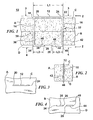
FIG. 1 is a side view, partially shown in section, of one embodiment of a disclosed substantially box staple formed through a pair of tissue sections; -
FIG. 2 is an end view taken along line 2-2 ofFIG. 1 ; -
FIG. 3 is a top view taken along line 3-3 ofFIG. 1 ; -
FIG. 4 is a bottom view taken along line 4-4 ofFIG. 1 ; -
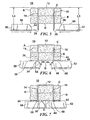
FIG. 5 is a side view, partially shown in section, of the staple ofFIG. 1 , inserted through the pair of relatively thick tissue sections, immediately prior to formation; -
FIG. 6 is a side view similar toFIG. 5 during formation of the staple through the pair of relatively thick tissue sections; -
FIG. 7 is a side view similar toFIG. 6 after formation of the staple through the pair of relatively thick tissue sections; -
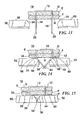
FIG. 8 is perspective view of the fully formed substantially box staple (when formed in relatively thin tissue sections); -
FIG. 9 is a side view, partially shown in section, of the staple ofFigure 8 formed through a pair of relatively thin tissue sections; -
FIG. 10 is a top view taken along line 10-10 ofFIG. 9 ; -
FIG. 11 is an end view taken along line 11-11 ofFIG. 9 ; -
FIG. 12 is a bottom view taken along line 12-12 ofFIG. 9 ; -
FIG. 13 is a side view, partially shown in section, of the staple immediately prior to formation through the pair of relatively thin tissue sections; -
FIG. 14 is a side view similar toFIG. 13 during formation of the staple through the pair of relatively thin tissue sections; -
FIG. 15 is similar toFIG. 14 after formation of the staple through the pair of relatively thin tissue sections; -
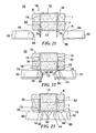
FIG. 16 is a perspective view of a staple assembly including a substantially box staple and a staple plate; -
FIG. 17 is a side view, partially shown in section, of the staple assembly formed through a pair of relatively thick tissue sections; -
FIG. 18 is an end view taken along line 18-18 ofFIG. 17 ; -
FIG. 19 is a top view taken along line 19-19 ofFIG. 17 ; -
FIG. 20 is a bottom view taken along line 20-20 ofFIG. 17 ; -
FIG. 21 is a side view, partially shown in section, of the staple assembly ofFig. 16 immediately prior to formation through the pair of relatively thick tissue sections; -
FIG. 22 is a side view, similar toFIG. 21 , during formation of the staple assembly through the pair of relatively thick tissue sections; -
FIG. 23 is a side view, similar toFIG. 22 , after formation of the staple assembly through the pair of relatively thick tissue sections; -
FIG. 24 is side view, partially shown in section, of the staple assembly formed through a pair of relatively thin tissue sections; -
FIG. 25 is a top view taken along line 25-25 ofFIG. 24 ; -
FIG. 26 is a bottom view taken along line 26-26 ofFIG. 24 ; -
FIG. 27 is an end view taken along line 27-27 ofFIG. 24 ; -
FIG. 28 is a side view, partially shown in section, of an alternate embodiment of a staple assembly including a staple and an arcuate staple plate shown formed through a pair of relatively thick tissue sections; and -
FIG. 29 is a side view, partially shown in section, of the staple assembly ofFIG. 28 formed through a pair of relatively thin tissue sections. - Embodiments of the presently disclosed staple and staple assembly will now be described in detail with reference to the drawings wherein like numerals designate identical or corresponding elements in each of the several views. As is common in the art, the term 'proximal" refers to that part or component closer to the user or operator, i.e. surgeon or physician, while the term "distal" refers to that part or component further away from the user.
- Referring to
FIG. 1-4 , and initially toFIG. 1 , there is disclosed an embodiment of auniversal staple 10 for use in various thickness of tissues.Staple 10 is substantially box-shaped and has the further advantage of providing uniform pressure against the underside of the tissues stapled as described in more detail hereinbelow. Substantially box-shapedstaple 10 generally includes abackspan 12 and first andsecond legs backspan 12. Specifically, afirst end 18 offirst leg 14 extends downwardly (as viewed inFig.1 ) from afirst end 20 ofbackspan 12 and asecond end 22 ofsecond leg 16 extends downwardly from asecond end 24 ofbackspan 12.First leg 14 terminates in atissue penetrating tip 26 andsecond leg 16 terminates in atissue penetrating tip 28. Thelegs legs - Substantially
box staple 10 is preferably formed from a length of material having a generally rectangular cross-section, although other cross sections are also contemplated.Staple 10 can be formed from any number of biocompatible materials such as, for example, stainless steel, titanium, various malleable plastic materials, various bio-absorbable materials etc. When formed from metallic materials such as stainless steel or titanium,staple 10 can be formed by drawing and cutting a length of metallic wire, stampingbox staple 10 from a sheet of metallic material, etc. Whenstaple 10 is formed from a plastic or bio-absorbable material,staple 10 can be formed by injection molding, carvingstaple 10 from a block of plastic material, etc. - As noted above,
staple 10 is designed for use in tissues of various thicknesses, such as, for example, relatively thick tissues A and B. In order to accommodate the various thickness tissues without excessive or insufficient compression of tissues A and B,first leg 14 has afirst bend zone 30 which extends substantially betweenfirst end 18 andtissue penetrating tip 26 offirst leg 14. Depending upon the thickness of the tissues encountered,first leg 14 can be bent at any location withinbend zone 30 to accommodate those tissues. This is facilitated by the use of a pair of anvils as described in more detail herein below.Second leg 16 also includes asecond bend zone 32 which extends substantially betweensecond end 22 andtissue penetrating tip 28 ofsecond leg 16 and can be bent at any location withinbend zone 32. - When
staple 10 is fully formed through relatively thick tissues A and B, backspan 12 provides uniform compression on an upper surface C of relatively thick tissue section A (FIGS. 1 and 3 ).First leg 14 is formed with afirst bend 34 infirst transition zone 30 such thatfirst leg 14 is divided into a first, substantially lineartraversing leg portion 36 extending through relatively thick tissues A and B (FIG. 1 ) and a first substantially linearclenching leg portion 38 lying substantially flush with an underside D of relatively thick tissue section B (FIGS.1 and 4 ). It should be noted thatfirst bend 34 formed between first traversingleg portion 36 and first clenchingleg portion 38 is preferably a substantially sharp or abrupt 90° bend in contrast to the relatively gradually curving bends typically associated with prior art staples. Likewise,second leg 16 is formed with asecond bend 40 insecond bend zone 32 which dividessecond leg 16 into a second substantially lineartraversing leg portion 42 extending through relatively thick tissue sections A and B (FIGS. 1 and 2 ) and a second substantially linearclenching leg portion 44 lying substantially flush with underside D of relatively thick tissue section B. (FIGS. 1 and 4 ).Second bend 40 also preferably forms a relatively sharp or abrupt 90° transition between second traversingleg portion 42 and second clenching likeportion 44. By maintaining first and secondclenching leg portions leg portion 38 and secondclenching leg portion 44 maintain a uniform compression against underside D without the associated pinching or tip penetration of underside D. - As best shown in
FIG. 1 , whenstaple 10 is formed through relatively thick tissue sections A and B, the length L1 ofbackspan 12 is preferably greater than or equal to the combined lengths L2 and L3 of first and second linear clenchingleg portions - Referring now to
FIGS. 5-7 , and initially with respect toFIG. 5 , the use and formation ofstaple 10 with relatively thick tissue sections A and B will now be described. Initially, the dimensions ofstaple 10 are preferably chosen such thatlegs second legs backspan 12. This ensures sufficient leg length to traverse and secure both relatively thick and thin tissue sections.Staple 10 is initially driven through relatively thick tissue sections A and B by engagingbackspan 12 with a staple driver (not shown) thereby driving first and secondtissue penetrating tips - Referring to
FIG. 6 , thereafter, a pair of anvils, such as, for example, first and second drivenanvils staple legs anvils angled surfaces angled surfaces second legs second bend zones second bends first bend zone 30 offirst leg 14 into first traversingleg portion 36 and first linearclenching leg portion 38. Similarly, this dividessecond bend zone 32 into secondtraversing leg portion 42 and second linear clenchingleg portion 44. - Referring to
FIG. 7 , as first andsecond anvils leg portions anvils leg portions staple 10 is used in relatively thin tissue sections, the combined lengths L2 and L3 of first and secondclenching leg portions backspan 12. - Referring now to
FIGS. 8-12 , and initially with regard toFIG. 8 , substantially boxstaple 10 is illustrated in the configuration it assumes when used through a pair of relatively thin tissue sections. Specifically, whenstaple 10 is formed through relatively thin tissue sections, each of the lengths L2 and L3 of respective first and second linear clenchingleg portions backspan 12. - As shown in
Figure 9 , first and secondtraversing leg portions leg portions FIG. 10 ,backspan 12 engages an upper surface G of tissue section E while first and second linear clenchingleg portions - As best shown in
FIGS. 8, 11 and 12 , the excess lengths of first and secondclenching leg portions tissue penetrating tips second legs - Referring now to
FIGS. 13-15 , in order to form staple 10 through pair of relatively thin tissue sections E and F,staple 10 is initially driven through tissue sections E and F. Thereafter, drivenanvils impact staple legs staple legs Figure 14 , angled faces 54 and 56 of drivenstaples traversing leg portions leg portions FIG. 15 , finishingsurfaces anvils leg portions leg portions backspan 12. Thus,staple 10 is particularly suited for use with relatively thin tissue sections such that first and second linear clenchingleg portions - Referring now to
FIGS. 16-20 , and initially with regard toFIG. 16 there is disclosed an alternate embodiment having astaple assembly 70 including a substantially box-shapedstaple 10 and a pledget orstaple plate 72.Staple plate 72 increases the surface area engaging a tissue being stapled as well as protecting the tissue from engagement withstaple legs staple 10 about tissue.Staple 10 is as described herein above includingbackspan 12 andlegs backspan 12. -
Staple plate 72 is substantially rectangular as shown (although other shapes are also contemplated) having first andsecond holes second holes second legs staple 10 therethrough.Staple plate 72 has an overall length L7 which is preferably greater than the length L1 of backspan 12 (FIG. 1 ). Additionally, the spacing or length L6 betweenholes backspan 12 as thelegs - As best shown in
FIGS. 17 and 18 ,staple assembly 70 is provided to secure a pair of tissue sections, such as, for example, tissue sections I andJ. Backspan 12 engages an upper surface K of tissue section I (FIG. 19 ) while anupper surface 82 ofstaple plate 72 engages a lower surface L of tissue section J (FIG. 20 ). - Referring to
FIG. 20 , as noted above,staple plate 72 protects tissue section J from engagement with first and secondclenching leg portions second legs staple 10 through tissue sections I and J,staple plate 72 is interposed between tissue section J and first and secondclenching leg portions - Referring to
FIGS. 21-23 , the use ofstaple assembly 70 to secure a pair of relatively thick tissue sections I and J together will now be described. With reference toFIG. 21 , initially,staple 10 is driven by a staple driver (not shown) toward tissue sections I and J such that first andsecond legs backspan 12 engages upper surface K of tissue sectionI. Staple plate 72 is positioned against undersurface K of tissue section J andlegs holes staple plate 72. This bringsupper surface 82 ofstaple plate 72 into engagement with undersurface K of tissue section J. - With reference to
FIGS. 21 and 22 , thereafter, first and second drivenanvils second legs angled surfaces second legs second legs respective bend zones second bends second legs first bend 34 dividesfirst leg 14 into first traversingleg portion 36 and first linearclenching leg portion 38 whilesecond bend 40 dividessecond leg 16 into secondtraversing leg portion 42 and second linear clenchingleg portion 44. Notably, the extension of first andsecond legs second holes staple plate 72 facilitate formingbends traversing leg portions second legs - Finally, with reference to
FIG. 23 , engagement of first and second finishing surfaces 58 and 60 of the first and second drivenanvils leg portions leg portions underside 84 ofstaple plate 72 thereby securingstaple plate 84 against underside L of tissue section J. - Referring now to
FIGS. 24-27 , the use ofstaple assembly 70 to secure a pair of relatively thin tissue sections, such as, for example, tissue sections M and N will now be described. The method disclosed herein with respect to relatively thin tissue sections M and N is substantially identical to the method disclosed herein above with respect to relatively thick tissue sections I and J. Initially, with reference toFIG. 24 ,staple 10 is driven by a staple driver (not shown) such that first andsecond legs backspan 12 engages an upper surface O of tissue section M (FIG. 25 ). Further movement of the staple driver drives first andsecond legs holes staple plate 72. Thereafter, first and second drivenanvils 50 and 52 (FIGS. 21-23 ) are moved toward each other as described above to form first and second linear clenchingleg portions underside 84 of staple plate 72 (FIG. 26 ). - As best shown in
FIGS. 26 and 27 , similar to that disclosed hereinabove with respect to staple 10 inFIGS. 11 and 12 , first and second linear clenchingleg portions legs box staple 10 having first andsecond legs backspan 12 allowsstaple 10 to function as a universal staple suitable for use with various thicknesses of tissue. As noted hereinabove, the provision ofstaple plate 72 provides additional surface bearing area against the tissue section while facilitating forming an abrupt 90° bend within first andsecond legs - Referring now to
FIGS. 28 and 29 , whilestaple plate 72 has been disclosed for use withstaple 10,staple plate 72 may be formed of a material which allowsstaple plate 72 to be used with a staple 90 similar tostaple 10 in situations whereinstaple 90 is formed with conventional anvils. As used herein, the term "conventional anvils" refers to those anvils having arcuate anvil pockets resulting in arcuate rather than linear clenching leg portions in the formed staple. - For example, with reference to
FIG. 28 ,staple 90 includes a backspan 92 having first andsecond legs backspan 92. In use,staple 90 is driven through relatively thick tissue sections Q and R resulting in first and secondtraversing leg portions backspan 92 engages an upper surface S of tissue section Q. First andsecond legs holes staple plate 72 and are clenched againststaple plate 72 by arcuate anvil pockets formed in an anvil associated with a conventional stapler (not shown). - Similarly, with reference to
FIG. 29 , when used in conjunction with relatively thin tissue sections U and V, backspan 92 engages an upper surface W of tissue section U while traversingleg portions V. Staple plate 72 bears against an undersurface X of tissue section V. First and secondclenching leg portions second legs legs - As shown in
Figures 28 and 29 ,staple plate 104 is preferably curved, thereby an arcuate top surface of the plate abuts the bottom surface of the tissue section R or V. - It will be understood that various modifications may be made to the embodiments disclosed herein. For example, the legs of the disclosed substantially box staple may be heat treated at specific points to facilitate the formation of the abrupt 90° bend between the traversing portion of the leg and the linear clenching portion of the leg. Further, alternative embodiments of anvils may be provided to form the substantially right angle within their respective legs. Additionally, the disclosed staple may be formed from a shape memory alloy such that the substantially right angle between the traversing leg portion and the substantially linear clenching leg portion is formed at a predetermined location along the length of the leg. Also curved or planar plates can be used with the embodiments of the staple disclosed herein. Therefore, the above description should not be construed as limiting, but merely as exemplifications of particular embodiments. Those skilled in the art will envision other modifications within the scope and spirit of the claims appended hereto.
Claims (11)
- A substantially box-shaped staple for use in tissue comprising:a backspan;a first leg extending from the backspan, the first leg being divided into a first traversing leg portion and a first substantially linear clenching leg portion by a first bend; anda second leg extending from the backspan, the second leg being divided into a second traversing leg portion and a second substantially linear clenching leg portion by a second bend, wherein at least one of the first and second substantially linear clenching leg portions is oriented substantially parallel to the backspan.
- The staple as recited in claim 1, wherein both the first and second linear clenching leg portions are oriented substantially parallel to the backspan.
- The staple as recited in claim 1, wherein at least one of the first and second traversing leg portions is oriented substantially perpendicular to the backspan.
- The staple as recited in claim 3, wherein both the first and second traversing leg portions are oriented substantially perpendicular to the backspan.
- The staple as recited in claim 1, wherein a combined length of the first and second clenching leg portions is less than an overall length of the backspan.
- The staple as recited in claim 1, wherein a combined length of the first and second clenching leg portions is equal to an overall length of the backspan.
- The staple as recited in claim 1, wherein a combined length of the first and second clenching leg portions is greater than an overall length of the backspan.
- A substantially box-shaped staple assembly for use in tissue comprising:a backspan;a first leg extending from the backspan, the first leg being divided into a first traversing leg portion and a first substantially linear clenching leg portion by a first bend;a second leg extending from the backspan, the second leg being divided into a second traversing leg portion and a second substantially linear clenching leg portion by a second bend; anda staple plate positioned on the first and second legs between the backspan and the first and second clenching leg portions, wherein at least one of the first and second substantially linear clenching leg portions is oriented substantially parallel to the staple plate.
- The staple assembly as recited in claim 8, wherein the staple plate has first and second holes to receive the first and second traversing leg portions respectively.
- The staple assembly as recited in claim 8, wherein an overall length of the staple plate is greater than an overall length of the backspan.
- The staple assembly as recited in claim 9, wherein the distance between the first and second holes is substantially equal to an overall length of the backspan.
Applications Claiming Priority (2)
| Application Number | Priority Date | Filing Date | Title |
|---|---|---|---|
| US8285208P | 2008-07-23 | 2008-07-23 | |
| US12/486,819 US20100023052A1 (en) | 2008-07-23 | 2009-06-18 | Staple for use in surgical procedures |
Publications (2)
| Publication Number | Publication Date |
|---|---|
| EP2147641A1 true EP2147641A1 (en) | 2010-01-27 |
| EP2147641B1 EP2147641B1 (en) | 2013-04-10 |
Family
ID=41057571
Family Applications (1)
| Application Number | Title | Priority Date | Filing Date |
|---|---|---|---|
| EP09251793.7A Ceased EP2147641B1 (en) | 2008-07-23 | 2009-07-15 | Staple for use in surgical procedures |
Country Status (3)
| Country | Link |
|---|---|
| US (3) | US20100023052A1 (en) |
| EP (1) | EP2147641B1 (en) |
| CA (1) | CA2671072C (en) |
Cited By (3)
| Publication number | Priority date | Publication date | Assignee | Title |
|---|---|---|---|---|
| EP2572653A1 (en) * | 2011-09-20 | 2013-03-27 | implantcast GmbH | Wound clamp |
| EP3260057A1 (en) * | 2016-06-24 | 2017-12-27 | Ethicon LLC | Stapling system for use with wire staples and stamped staples |
| US10405958B2 (en) | 2014-04-04 | 2019-09-10 | Boston Scientific Scimed, Inc. | Devices and methods for fixation of bodily implants |
Families Citing this family (35)
| Publication number | Priority date | Publication date | Assignee | Title |
|---|---|---|---|---|
| US11957334B2 (en) | 2012-07-30 | 2024-04-16 | Conextions, Inc. | Devices, systems, and methods for repairing soft tissue and attaching soft tissue to bone |
| US11253252B2 (en) | 2012-07-30 | 2022-02-22 | Conextions, Inc. | Devices, systems, and methods for repairing soft tissue and attaching soft tissue to bone |
| US10219804B2 (en) | 2012-07-30 | 2019-03-05 | Conextions, Inc. | Devices, systems, and methods for repairing soft tissue and attaching soft tissue to bone |
| US11944531B2 (en) | 2012-07-30 | 2024-04-02 | Conextions, Inc. | Devices, systems, and methods for repairing soft tissue and attaching soft tissue to bone |
| US10390935B2 (en) | 2012-07-30 | 2019-08-27 | Conextions, Inc. | Soft tissue to bone repair devices, systems, and methods |
| US9289207B2 (en) * | 2012-11-29 | 2016-03-22 | Ethicon Endo-Surgery, Llc | Surgical staple with integral pledget for tip deflection |
| US9968354B2 (en) | 2013-12-23 | 2018-05-15 | Ethicon Llc | Surgical staples and methods for making the same |
| US9839428B2 (en) | 2013-12-23 | 2017-12-12 | Ethicon Llc | Surgical cutting and stapling instruments with independent jaw control features |
| US9724092B2 (en) | 2013-12-23 | 2017-08-08 | Ethicon Llc | Modular surgical instruments |
| US20150173756A1 (en) | 2013-12-23 | 2015-06-25 | Ethicon Endo-Surgery, Inc. | Surgical cutting and stapling methods |
| US12508019B2 (en) | 2014-03-12 | 2025-12-30 | Conextions, Inc. | Devices, systems, and methods for repairing soft tissue and attaching soft tissue to bone |
| US11583384B2 (en) | 2014-03-12 | 2023-02-21 | Conextions, Inc. | Devices, systems, and methods for repairing soft tissue and attaching soft tissue to bone |
| CN108348239B (en) | 2015-08-26 | 2021-03-09 | 伊西康有限责任公司 | Staple cartridge assembly including various tissue compression gaps and staple forming gaps |
| US10433845B2 (en) | 2015-08-26 | 2019-10-08 | Ethicon Llc | Surgical staple strips for permitting varying staple properties and enabling easy cartridge loading |
| RU2725081C2 (en) | 2015-08-26 | 2020-06-29 | ЭТИКОН ЭлЭлСи | Strips with surgical staples allowing the presence of staples with variable properties and providing simple loading of the cartridge |
| MX2022009705A (en) | 2015-08-26 | 2022-11-07 | Ethicon Llc | Surgical staples comprising hardness variations for improved fastening of tissue. |
| US10314587B2 (en) | 2015-09-02 | 2019-06-11 | Ethicon Llc | Surgical staple cartridge with improved staple driver configurations |
| MX2022006192A (en) | 2015-09-02 | 2022-06-16 | Ethicon Llc | Surgical staple configurations with camming surfaces located between portions supporting surgical staples. |
| USD826405S1 (en) | 2016-06-24 | 2018-08-21 | Ethicon Llc | Surgical fastener |
| CN109310431B (en) | 2016-06-24 | 2022-03-04 | 伊西康有限责任公司 | Staple cartridge comprising wire staples and punch staples |
| USD850617S1 (en) | 2016-06-24 | 2019-06-04 | Ethicon Llc | Surgical fastener cartridge |
| JP6980705B2 (en) | 2016-06-24 | 2021-12-15 | エシコン エルエルシーEthicon LLC | Stapling system for use with wire staples and punched staples |
| USD847989S1 (en) | 2016-06-24 | 2019-05-07 | Ethicon Llc | Surgical fastener cartridge |
| US11696822B2 (en) | 2016-09-28 | 2023-07-11 | Conextions, Inc. | Devices, systems, and methods for repairing soft tissue and attaching soft tissue to bone |
| US10945727B2 (en) | 2016-12-21 | 2021-03-16 | Ethicon Llc | Staple cartridge with deformable driver retention features |
| US10687810B2 (en) | 2016-12-21 | 2020-06-23 | Ethicon Llc | Stepped staple cartridge with tissue retention and gap setting features |
| US10993715B2 (en) | 2016-12-21 | 2021-05-04 | Ethicon Llc | Staple cartridge comprising staples with different clamping breadths |
| US11684367B2 (en) | 2016-12-21 | 2023-06-27 | Cilag Gmbh International | Stepped assembly having and end-of-life indicator |
| US20180168650A1 (en) | 2016-12-21 | 2018-06-21 | Ethicon Endo-Surgery, Llc | Connection portions for disposable loading units for surgical stapling instruments |
| US11517325B2 (en) | 2017-06-20 | 2022-12-06 | Cilag Gmbh International | Closed loop feedback control of motor velocity of a surgical stapling and cutting instrument based on measured displacement distance traveled over a specified time interval |
| US11547397B2 (en) | 2017-12-20 | 2023-01-10 | Conextions, Inc. | Devices, systems, and methods for repairing soft tissue and attaching soft tissue to bone |
| US12102317B2 (en) | 2017-12-20 | 2024-10-01 | Conextions, Inc. | Devices, systems, and methods for repairing soft tissue and attaching soft tissue to bone |
| US11331130B1 (en) * | 2020-12-10 | 2022-05-17 | DePuy Synthes Products, Inc. | Sternal closure systems and methods of use thereof |
| US12446938B2 (en) | 2023-01-12 | 2025-10-21 | DePuy Synthes Products, Inc. | Orthopedic fixation system |
| US12539151B2 (en) | 2024-07-18 | 2026-02-03 | DePuy Synthes Products, Inc. | Orthopedic fixation system |
Citations (7)
| Publication number | Priority date | Publication date | Assignee | Title |
|---|---|---|---|---|
| US3837555A (en) | 1970-12-14 | 1974-09-24 | Surgical Corp | Powering instrument for stapling skin and fascia |
| US4014492A (en) * | 1975-06-11 | 1977-03-29 | Senco Products, Inc. | Surgical staple |
| GB2019296A (en) * | 1978-04-24 | 1979-10-31 | Smith L M | Surgical stapler and staple |
| GB2051287A (en) * | 1979-05-14 | 1981-01-14 | Senco Products | Surgical staple |
| EP0588081A2 (en) * | 1992-08-18 | 1994-03-23 | United States Surgical Corporation | Surgical fastening device |
| US5470010A (en) | 1991-04-04 | 1995-11-28 | Ethicon, Inc. | Multiple fire endoscopic stapling mechanism |
| EP1728473A1 (en) | 2005-06-02 | 2006-12-06 | Tyco Healthcare Group Lp | Expandable backspan staple |
Family Cites Families (121)
| Publication number | Priority date | Publication date | Assignee | Title |
|---|---|---|---|---|
| US352410A (en) * | 1886-11-09 | Device for attaching tags | ||
| US3643851A (en) * | 1969-08-25 | 1972-02-22 | United States Surgical Corp | Skin stapler |
| US3598299A (en) * | 1970-01-02 | 1971-08-10 | Mark S Johnson | Stapling tool for cattle |
| SU405234A1 (en) | 1970-09-02 | 1975-09-05 | Всесоюзный Научно-Исследовательский Институт Хирургической Аппаратуры И Инструментов | Matrix for suturing surgical apparatus |
| US3771526A (en) * | 1972-02-07 | 1973-11-13 | P Rudie | Anastomosis clamp |
| CH635505A5 (en) | 1978-08-28 | 1983-04-15 | Vnii Ispytatel Med Tech | Surgical suturing device for suturing organs with metal clips |
| US4391401A (en) * | 1979-04-03 | 1983-07-05 | Lawrence M. Smith | Surgical staplers and staple |
| US4319576A (en) * | 1980-02-26 | 1982-03-16 | Senco Products, Inc. | Intralumenal anastomosis surgical stapling instrument |
| US4809695A (en) * | 1981-10-21 | 1989-03-07 | Owen M. Gwathmey | Suturing assembly and method |
| US4610383A (en) * | 1983-10-14 | 1986-09-09 | Senmed, Inc. | Disposable linear surgical stapler |
| US4741336A (en) * | 1984-07-16 | 1988-05-03 | Ethicon, Inc. | Shaped staples and slotted receivers (case VII) |
| US4605001A (en) * | 1984-10-19 | 1986-08-12 | Senmed, Inc. | Surgical stapling instrument with dual staple height mechanism |
| US4608981A (en) * | 1984-10-19 | 1986-09-02 | Senmed, Inc. | Surgical stapling instrument with staple height adjusting mechanism |
| US4767044A (en) * | 1984-10-19 | 1988-08-30 | United States Surgical Corporation | Surgical fastener applying apparatus |
| SU1333319A2 (en) | 1985-12-10 | 1987-08-30 | Петрозаводский государственный университет им.О.В.Куусинена | Suture appliance for hollow organs |
| SU1459659A1 (en) | 1986-09-29 | 1989-02-23 | Всесоюзный научно-исследовательский и испытательный институт медицинской техники | Surgical suturing apparatus for applying line sutures |
| SU1442191A1 (en) | 1987-01-19 | 1988-12-07 | Петрозаводский государственный университет им.О.В.Куусинена | Surgical suturing apparatus |
| US4747531A (en) * | 1987-03-23 | 1988-05-31 | Ethicon, Inc. | Anvil and driver assembly for a surgical skin stapling instrument |
| US4941623A (en) * | 1987-05-12 | 1990-07-17 | United States Surgical Corporation | Stapling process and device for use on the mesentery of the abdomen |
| US4930503A (en) * | 1987-06-11 | 1990-06-05 | Pruitt J Crayton | Stapling process and device for use on the mesenteries of the abdomen |
| US4848637A (en) * | 1987-06-11 | 1989-07-18 | Pruitt J Crayton | Staple device for use on the mesenteries of the abdomen |
| US5027834A (en) * | 1987-06-11 | 1991-07-02 | United States Surgical Corporation | Stapling process for use on the mesenteries of the abdomen |
| JPH02121645A (en) * | 1988-10-31 | 1990-05-09 | Matsutani Seisakusho Co Ltd | Medical staples and their manufacturing method |
| AU4633589A (en) | 1988-11-18 | 1990-06-12 | Immuno Sweden Ab | Instrument for anastomosis |
| US4881545A (en) * | 1988-12-08 | 1989-11-21 | United States Surgical Corporation | Surgical fastener cartridge with improved body tissue cutting knife assembly |
| US4978049A (en) * | 1989-05-26 | 1990-12-18 | United States Surgical Corporation | Three staple drive member |
| GB9020379D0 (en) * | 1990-09-18 | 1990-10-31 | Femcare Ltd | Suture apparatus |
| US5108422A (en) * | 1990-10-22 | 1992-04-28 | United States Surgical Corporation | Skin fastener |
| US5425489A (en) * | 1990-12-20 | 1995-06-20 | United States Surgical Corporation | Fascia clip and instrument |
| US5571285A (en) * | 1991-02-19 | 1996-11-05 | Ethicon, Inc. | Surgical staple for insertion into tissue |
| US5282829A (en) * | 1991-08-15 | 1994-02-01 | United States Surgical Corporation | Hollow body implants |
| US5201746A (en) * | 1991-10-16 | 1993-04-13 | United States Surgical Corporation | Surgical hemostatic clip |
| US5443198A (en) * | 1991-10-18 | 1995-08-22 | United States Surgical Corporation | Surgical fastener applying apparatus |
| US5350400A (en) * | 1991-10-30 | 1994-09-27 | American Cyanamid Company | Malleable, bioabsorbable, plastic staple; and method and apparatus for deforming such staple |
| US5240163A (en) * | 1991-10-30 | 1993-08-31 | American Cyanamid Company | Linear surgical stapling instrument |
| US5180092A (en) * | 1992-02-05 | 1993-01-19 | Lawrence Crainich | Linear surgical stapling instrument |
| US5219353A (en) * | 1992-02-28 | 1993-06-15 | Garvey Iii Thomas Q | Surgical endoclip |
| US5484095A (en) * | 1992-03-31 | 1996-01-16 | United States Surgical Corporation | Apparatus for endoscopically applying staples individually to body tissue |
| JPH0675830B2 (en) * | 1992-08-24 | 1994-09-28 | 丸善株式会社 | Stepper |
| US5342396A (en) * | 1993-03-02 | 1994-08-30 | Cook Melvin S | Staples |
| CA2120828C (en) * | 1993-04-16 | 1999-11-02 | Paul J. Phillips | Surgical hemostatic clip |
| US5415334A (en) * | 1993-05-05 | 1995-05-16 | Ethicon Endo-Surgery | Surgical stapler and staple cartridge |
| GR940100335A (en) | 1993-07-22 | 1996-05-22 | Ethicon Inc. | Electrosurgical device for placing staples. |
| US5709680A (en) * | 1993-07-22 | 1998-01-20 | Ethicon Endo-Surgery, Inc. | Electrosurgical hemostatic device |
| US5452837A (en) * | 1994-01-21 | 1995-09-26 | Ethicon Endo-Surgery, Inc. | Surgical stapler with tissue gripping ridge |
| US5452836A (en) * | 1994-02-07 | 1995-09-26 | Ethicon Endo-Surgery, Inc. | Surgical stapling instrument with improved jaw closure and staple firing actuator mechanism |
| FR2719211B1 (en) * | 1994-04-27 | 1996-07-19 | Mortier Jean Pierre | Equipment for correcting foot deformities. |
| US5501693A (en) * | 1994-07-06 | 1996-03-26 | United States Surgical Corporation | Surgical hemostatic clip |
| US5571116A (en) * | 1994-10-02 | 1996-11-05 | United States Surgical Corporation | Non-invasive treatment of gastroesophageal reflux disease |
| DE19509966A1 (en) * | 1995-03-18 | 1996-09-19 | Frank Ullrich Schuetz | Stapler and nail for surgery |
| US5634926A (en) * | 1995-04-25 | 1997-06-03 | Jobe; Richard P. | Surgical bone fixation apparatus |
| US5667526A (en) | 1995-09-07 | 1997-09-16 | Levin; John M. | Tissue retaining clamp |
| US5697542A (en) * | 1995-10-19 | 1997-12-16 | Ethicon Endo-Surgery, Inc. | Endoscopic surgical stapler with compact profile |
| US5941442A (en) * | 1995-10-27 | 1999-08-24 | United States Surgical | Surgical stapler |
| US20020068949A1 (en) * | 1996-02-23 | 2002-06-06 | Williamson Warren P. | Extremely long wire fasteners for use in minimally invasive surgery and means and method for handling those fasteners |
| US5810240A (en) * | 1996-03-15 | 1998-09-22 | United States Surgical Corporation | Surgical fastener applying device |
| IL117607A0 (en) | 1996-03-21 | 1996-07-23 | Dev Of Advanced Medical Produc | Surgical stapler and method of surgical fastening |
| USH2037H1 (en) | 1997-05-14 | 2002-07-02 | David C. Yates | Electrosurgical hemostatic device including an anvil |
| US5865361A (en) * | 1997-09-23 | 1999-02-02 | United States Surgical Corporation | Surgical stapling apparatus |
| US6083242A (en) * | 1999-02-17 | 2000-07-04 | Holobeam, Inc. | Surgical staples with deformation zones of non-uniform cross section |
| US6059787A (en) * | 1999-04-26 | 2000-05-09 | Allen; Drew | Compression bone staple apparatus and method |
| US8025199B2 (en) * | 2004-02-23 | 2011-09-27 | Tyco Healthcare Group Lp | Surgical cutting and stapling device |
| US6325810B1 (en) * | 1999-06-30 | 2001-12-04 | Ethicon, Inc. | Foam buttress for stapling apparatus |
| CA2322061A1 (en) | 1999-10-05 | 2001-04-05 | Anil K. Nalagatla | Stapling instrument having two staple forming surfaces |
| SE522763C2 (en) * | 1999-11-19 | 2004-03-02 | Isaberg Rapid Ab | Stapler driver intended for mounting in a stapler |
| BR0109404A (en) | 2000-03-20 | 2003-06-03 | By Pass Inc | Medical graft delivery system, removable graft guide for a graft delivery system, and pot puller |
| EP1330189B1 (en) * | 2000-06-23 | 2007-12-19 | Viacor Incorporated | Automated annular plication for mitral valve repair |
| US6817508B1 (en) | 2000-10-13 | 2004-11-16 | Tyco Healthcare Group, Lp | Surgical stapling device |
| US20040267310A1 (en) * | 2000-10-20 | 2004-12-30 | Racenet David C | Directionally biased staple and anvil assembly for forming the staple |
| JP2002159500A (en) * | 2000-11-28 | 2002-06-04 | Koseki Ika Kk | Ligament fixing system |
| EP2397080B1 (en) * | 2001-04-03 | 2018-08-01 | Covidien LP | Surgical stapling device |
| IES20010547A2 (en) * | 2001-06-07 | 2002-12-11 | Christy Cummins | Surgical Staple |
| DE10158246C1 (en) | 2001-11-28 | 2003-08-21 | Ethicon Endo Surgery Europe | Surgical stapling instrument |
| WO2003086206A1 (en) * | 2002-04-11 | 2003-10-23 | Tyco Healthcare Group, Lp | Surgical stapling apparatus including an anvil and cartridge each having cooperating mating surfaces |
| FR2838952A1 (en) | 2002-04-26 | 2003-10-31 | Franck Marie Houe Zinzindohoue | Anvil device for setting of clips used as mechanical sutures in surgical applications includes a level structure on which are grooves for setting of the clips |
| AU2003239408B2 (en) | 2002-05-10 | 2008-09-04 | Covidien Lp | Wound closure material applicator and stapler |
| AU2003234551A1 (en) | 2002-05-13 | 2003-11-11 | Tyco Healthcare Group, Lp | Surgical stapler and disposable loading unit having different size staples |
| US7004950B1 (en) * | 2002-06-21 | 2006-02-28 | Collins James R | Tissue aligning surgical stapler and method of use |
| US7112273B2 (en) * | 2002-09-27 | 2006-09-26 | Nxstage Medical, Inc. | Volumetric fluid balance control for extracorporeal blood treatment |
| AU2003277294A1 (en) * | 2002-10-04 | 2004-05-04 | Tyco Healthcare Group, Lp | Angled surgical fastener apparatus |
| US7309342B2 (en) | 2003-01-16 | 2007-12-18 | Mark Genovesi | Heatless blood vessel harvesting device |
| US7044352B2 (en) * | 2003-05-20 | 2006-05-16 | Ethicon Endo-Surgery, Inc. | Surgical stapling instrument having a single lockout mechanism for prevention of firing |
| US7140528B2 (en) * | 2003-05-20 | 2006-11-28 | Ethicon Endo-Surgery, Inc. | Surgical stapling instrument having an electroactive polymer actuated single lockout mechanism for prevention of firing |
| US7380696B2 (en) * | 2003-05-20 | 2008-06-03 | Ethicon Endo-Surgery, Inc. | Articulating surgical stapling instrument incorporating a two-piece E-beam firing mechanism |
| US20070010838A1 (en) * | 2003-05-20 | 2007-01-11 | Shelton Frederick E Iv | Surgical stapling instrument having a firing lockout for an unclosed anvil |
| US7143923B2 (en) * | 2003-05-20 | 2006-12-05 | Ethicon Endo-Surgery, Inc. | Surgical stapling instrument having a firing lockout for an unclosed anvil |
| US7380695B2 (en) * | 2003-05-20 | 2008-06-03 | Ethicon Endo-Surgery, Inc. | Surgical stapling instrument having a single lockout mechanism for prevention of firing |
| US6988649B2 (en) * | 2003-05-20 | 2006-01-24 | Ethicon Endo-Surgery, Inc. | Surgical stapling instrument having a spent cartridge lockout |
| US7000818B2 (en) * | 2003-05-20 | 2006-02-21 | Ethicon, Endo-Surger, Inc. | Surgical stapling instrument having separate distinct closing and firing systems |
| US20040247415A1 (en) * | 2003-06-04 | 2004-12-09 | Mangone Peter G. | Slotted fastener and fastening method |
| US6981628B2 (en) * | 2003-07-09 | 2006-01-03 | Ethicon Endo-Surgery, Inc. | Surgical instrument with a lateral-moving articulation control |
| US6786382B1 (en) * | 2003-07-09 | 2004-09-07 | Ethicon Endo-Surgery, Inc. | Surgical stapling instrument incorporating an articulation joint for a firing bar track |
| US7055731B2 (en) * | 2003-07-09 | 2006-06-06 | Ethicon Endo-Surgery Inc. | Surgical stapling instrument incorporating a tapered firing bar for increased flexibility around the articulation joint |
| US7111769B2 (en) * | 2003-07-09 | 2006-09-26 | Ethicon Endo-Surgery, Inc. | Surgical instrument incorporating an articulation mechanism having rotation about the longitudinal axis |
| US6964363B2 (en) * | 2003-07-09 | 2005-11-15 | Ethicon Endo-Surgery, Inc. | Surgical stapling instrument having articulation joint support plates for supporting a firing bar |
| US7000819B2 (en) * | 2003-09-29 | 2006-02-21 | Ethicon Endo-Surgery, Inc. | Surgical stapling instrument having multistroke firing incorporating a traction-biased ratcheting mechanism |
| US7083075B2 (en) * | 2003-09-29 | 2006-08-01 | Ethicon Endo-Surgery, Inc. | Multi-stroke mechanism with automatic end of stroke retraction |
| US7303108B2 (en) * | 2003-09-29 | 2007-12-04 | Ethicon Endo-Surgery, Inc. | Surgical stapling instrument incorporating a multi-stroke firing mechanism with a flexible rack |
| US6959852B2 (en) * | 2003-09-29 | 2005-11-01 | Ethicon Endo-Surgery, Inc. | Surgical stapling instrument with multistroke firing incorporating an anti-backup mechanism |
| US6905057B2 (en) * | 2003-09-29 | 2005-06-14 | Ethicon Endo-Surgery, Inc. | Surgical stapling instrument incorporating a firing mechanism having a linked rack transmission |
| US7364061B2 (en) * | 2003-09-29 | 2008-04-29 | Ethicon Endo-Surgery, Inc. | Surgical stapling instrument incorporating a multistroke firing position indicator and retraction mechanism |
| US7434715B2 (en) * | 2003-09-29 | 2008-10-14 | Ethicon Endo-Surgery, Inc. | Surgical stapling instrument having multistroke firing with opening lockout |
| US20050283190A1 (en) * | 2004-06-16 | 2005-12-22 | Huitema Thomas W | Surgical fastener |
| US7367485B2 (en) | 2004-06-30 | 2008-05-06 | Ethicon Endo-Surgery, Inc. | Surgical stapling instrument incorporating a multistroke firing mechanism having a rotary transmission |
| US7059508B2 (en) * | 2004-06-30 | 2006-06-13 | Ethicon Endo-Surgery, Inc. | Surgical stapling instrument incorporating an uneven multistroke firing mechanism having a rotary transmission |
| US20060015144A1 (en) * | 2004-07-19 | 2006-01-19 | Vascular Control Systems, Inc. | Uterine artery occlusion staple |
| US8905977B2 (en) * | 2004-07-28 | 2014-12-09 | Ethicon Endo-Surgery, Inc. | Surgical stapling instrument having an electroactive polymer actuated medical substance dispenser |
| US7404509B2 (en) * | 2004-07-28 | 2008-07-29 | Ethicon Endo-Surgery, Inc. | Electroactive polymer-based articulation mechanism for linear stapler |
| US20060025812A1 (en) * | 2004-07-28 | 2006-02-02 | Ethicon Endo-Surgery, Inc. | Surgical instrument incorporating an electrically actuated pivoting articulation mechanism |
| US7857183B2 (en) * | 2004-07-28 | 2010-12-28 | Ethicon Endo-Surgery, Inc. | Surgical instrument incorporating an electrically actuated articulation mechanism |
| US20060039779A1 (en) * | 2004-07-28 | 2006-02-23 | Ringl Edward A | Snap staples |
| US7143925B2 (en) * | 2004-07-28 | 2006-12-05 | Ethicon Endo-Surgery, Inc. | Surgical instrument incorporating EAP blocking lockout mechanism |
| US8057508B2 (en) * | 2004-07-28 | 2011-11-15 | Ethicon Endo-Surgery, Inc. | Surgical instrument incorporating an electrically actuated articulation locking mechanism |
| US7487899B2 (en) * | 2004-07-28 | 2009-02-10 | Ethicon Endo-Surgery, Inc. | Surgical instrument incorporating EAP complete firing system lockout mechanism |
| US7506790B2 (en) * | 2004-07-28 | 2009-03-24 | Ethicon Endo-Surgery, Inc. | Surgical instrument incorporating an electrically actuated articulation mechanism |
| US7147138B2 (en) * | 2004-07-28 | 2006-12-12 | Ethicon Endo-Surgery, Inc. | Surgical stapling instrument having an electroactive polymer actuated buttress deployment mechanism |
| US7128254B2 (en) * | 2004-09-07 | 2006-10-31 | Ethicon Endo-Surgery, Inc. | Surgical stapling instrument incorporating a multistroke firing mechanism having a rotary slip-clutch transmission |
| US7654431B2 (en) * | 2005-02-18 | 2010-02-02 | Ethicon Endo-Surgery, Inc. | Surgical instrument with guided laterally moving articulation member |
| US20070023474A1 (en) * | 2005-07-14 | 2007-02-01 | Smith Robert S | Clincher for a heavy duty stapler |
| US7398908B2 (en) * | 2005-08-15 | 2008-07-15 | Tyco Healthcare Group Lp | Surgical stapling instruments including a cartridge having multiple staple sizes |
| US8220690B2 (en) * | 2006-09-29 | 2012-07-17 | Ethicon Endo-Surgery, Inc. | Connected surgical staples and stapling instruments for deploying the same |
-
2009
- 2009-06-18 US US12/486,819 patent/US20100023052A1/en not_active Abandoned
- 2009-07-02 CA CA2671072A patent/CA2671072C/en not_active Expired - Fee Related
- 2009-07-15 EP EP09251793.7A patent/EP2147641B1/en not_active Ceased
-
2012
- 2012-04-19 US US13/450,753 patent/US8579938B2/en not_active Expired - Fee Related
-
2013
- 2013-10-09 US US14/049,694 patent/US9693771B2/en not_active Expired - Fee Related
Patent Citations (7)
| Publication number | Priority date | Publication date | Assignee | Title |
|---|---|---|---|---|
| US3837555A (en) | 1970-12-14 | 1974-09-24 | Surgical Corp | Powering instrument for stapling skin and fascia |
| US4014492A (en) * | 1975-06-11 | 1977-03-29 | Senco Products, Inc. | Surgical staple |
| GB2019296A (en) * | 1978-04-24 | 1979-10-31 | Smith L M | Surgical stapler and staple |
| GB2051287A (en) * | 1979-05-14 | 1981-01-14 | Senco Products | Surgical staple |
| US5470010A (en) | 1991-04-04 | 1995-11-28 | Ethicon, Inc. | Multiple fire endoscopic stapling mechanism |
| EP0588081A2 (en) * | 1992-08-18 | 1994-03-23 | United States Surgical Corporation | Surgical fastening device |
| EP1728473A1 (en) | 2005-06-02 | 2006-12-06 | Tyco Healthcare Group Lp | Expandable backspan staple |
Cited By (4)
| Publication number | Priority date | Publication date | Assignee | Title |
|---|---|---|---|---|
| EP2572653A1 (en) * | 2011-09-20 | 2013-03-27 | implantcast GmbH | Wound clamp |
| US10405958B2 (en) | 2014-04-04 | 2019-09-10 | Boston Scientific Scimed, Inc. | Devices and methods for fixation of bodily implants |
| EP3260057A1 (en) * | 2016-06-24 | 2017-12-27 | Ethicon LLC | Stapling system for use with wire staples and stamped staples |
| WO2017223319A1 (en) * | 2016-06-24 | 2017-12-28 | Ethicon Llc | Stapling system for use with wire staples and stamped staples |
Also Published As
| Publication number | Publication date |
|---|---|
| EP2147641B1 (en) | 2013-04-10 |
| US9693771B2 (en) | 2017-07-04 |
| US20100023052A1 (en) | 2010-01-28 |
| CA2671072C (en) | 2016-10-11 |
| US20140039550A1 (en) | 2014-02-06 |
| CA2671072A1 (en) | 2010-01-23 |
| US20120203274A1 (en) | 2012-08-09 |
| US8579938B2 (en) | 2013-11-12 |
Similar Documents
| Publication | Publication Date | Title |
|---|---|---|
| CA2671072C (en) | Staple for use in surgical procedures | |
| AU704533B2 (en) | Improved staples | |
| US20230013791A1 (en) | Surgical staples and end effectors for deploying the same | |
| EP2067441B1 (en) | Surgical staple | |
| CA2090782C (en) | Surgical staples | |
| US8006888B2 (en) | Multiple coil staple and staple applier | |
| US8998951B2 (en) | Method of manufacturing surgical staples | |
| CA1053110A (en) | Surgical staple | |
| US9265500B2 (en) | Surgical staple | |
| US20090318957A1 (en) | Expandable backspan staple | |
| EP1349503B1 (en) | Anvil assembly for forming a staple | |
| AU2002309204A1 (en) | Surgical staple | |
| JPH0654856A (en) | Deformable bioabsorbable plastic staple having knot shape and method and apparatus for deforming such staple | |
| US20180317907A1 (en) | Surgical staples with expandable backspan | |
| EP0253629B1 (en) | Staple | |
| US10966723B2 (en) | Curvilinear surgical staples | |
| CN214342467U (en) | Absorbable anastomosis system | |
| AU2011202720B2 (en) | Multiple coil staple and staple applier | |
| CN112155624A (en) | Absorbable anastomosis system |
Legal Events
| Date | Code | Title | Description |
|---|---|---|---|
| PUAI | Public reference made under article 153(3) epc to a published international application that has entered the european phase |
Free format text: ORIGINAL CODE: 0009012 |
|
| AK | Designated contracting states |
Kind code of ref document: A1 Designated state(s): AT BE BG CH CY CZ DE DK EE ES FI FR GB GR HR HU IE IS IT LI LT LU LV MC MK MT NL NO PL PT RO SE SI SK SM TR |
|
| AX | Request for extension of the european patent |
Extension state: AL BA RS |
|
| 17P | Request for examination filed |
Effective date: 20100723 |
|
| 17Q | First examination report despatched |
Effective date: 20100920 |
|
| GRAP | Despatch of communication of intention to grant a patent |
Free format text: ORIGINAL CODE: EPIDOSNIGR1 |
|
| RAP1 | Party data changed (applicant data changed or rights of an application transferred) |
Owner name: COVIDIEN LP |
|
| GRAS | Grant fee paid |
Free format text: ORIGINAL CODE: EPIDOSNIGR3 |
|
| GRAA | (expected) grant |
Free format text: ORIGINAL CODE: 0009210 |
|
| AK | Designated contracting states |
Kind code of ref document: B1 Designated state(s): AT BE BG CH CY CZ DE DK EE ES FI FR GB GR HR HU IE IS IT LI LT LU LV MC MK MT NL NO PL PT RO SE SI SK SM TR |
|
| REG | Reference to a national code |
Ref country code: GB Ref legal event code: FG4D |
|
| REG | Reference to a national code |
Ref country code: AT Ref legal event code: REF Ref document number: 605524 Country of ref document: AT Kind code of ref document: T Effective date: 20130415 Ref country code: CH Ref legal event code: EP |
|
| REG | Reference to a national code |
Ref country code: IE Ref legal event code: FG4D |
|
| REG | Reference to a national code |
Ref country code: DE Ref legal event code: R096 Ref document number: 602009014806 Country of ref document: DE Effective date: 20130606 |
|
| PG25 | Lapsed in a contracting state [announced via postgrant information from national office to epo] |
Ref country code: SI Free format text: LAPSE BECAUSE OF FAILURE TO SUBMIT A TRANSLATION OF THE DESCRIPTION OR TO PAY THE FEE WITHIN THE PRESCRIBED TIME-LIMIT Effective date: 20130410 |
|
| REG | Reference to a national code |
Ref country code: AT Ref legal event code: MK05 Ref document number: 605524 Country of ref document: AT Kind code of ref document: T Effective date: 20130410 |
|
| REG | Reference to a national code |
Ref country code: NL Ref legal event code: VDEP Effective date: 20130410 Ref country code: LT Ref legal event code: MG4D |
|
| PG25 | Lapsed in a contracting state [announced via postgrant information from national office to epo] |
Ref country code: NO Free format text: LAPSE BECAUSE OF FAILURE TO SUBMIT A TRANSLATION OF THE DESCRIPTION OR TO PAY THE FEE WITHIN THE PRESCRIBED TIME-LIMIT Effective date: 20130710 Ref country code: ES Free format text: LAPSE BECAUSE OF FAILURE TO SUBMIT A TRANSLATION OF THE DESCRIPTION OR TO PAY THE FEE WITHIN THE PRESCRIBED TIME-LIMIT Effective date: 20130721 Ref country code: AT Free format text: LAPSE BECAUSE OF FAILURE TO SUBMIT A TRANSLATION OF THE DESCRIPTION OR TO PAY THE FEE WITHIN THE PRESCRIBED TIME-LIMIT Effective date: 20130410 Ref country code: SE Free format text: LAPSE BECAUSE OF FAILURE TO SUBMIT A TRANSLATION OF THE DESCRIPTION OR TO PAY THE FEE WITHIN THE PRESCRIBED TIME-LIMIT Effective date: 20130410 Ref country code: GR Free format text: LAPSE BECAUSE OF FAILURE TO SUBMIT A TRANSLATION OF THE DESCRIPTION OR TO PAY THE FEE WITHIN THE PRESCRIBED TIME-LIMIT Effective date: 20130711 Ref country code: FI Free format text: LAPSE BECAUSE OF FAILURE TO SUBMIT A TRANSLATION OF THE DESCRIPTION OR TO PAY THE FEE WITHIN THE PRESCRIBED TIME-LIMIT Effective date: 20130410 Ref country code: NL Free format text: LAPSE BECAUSE OF FAILURE TO SUBMIT A TRANSLATION OF THE DESCRIPTION OR TO PAY THE FEE WITHIN THE PRESCRIBED TIME-LIMIT Effective date: 20130410 Ref country code: IS Free format text: LAPSE BECAUSE OF FAILURE TO SUBMIT A TRANSLATION OF THE DESCRIPTION OR TO PAY THE FEE WITHIN THE PRESCRIBED TIME-LIMIT Effective date: 20130810 Ref country code: BE Free format text: LAPSE BECAUSE OF FAILURE TO SUBMIT A TRANSLATION OF THE DESCRIPTION OR TO PAY THE FEE WITHIN THE PRESCRIBED TIME-LIMIT Effective date: 20130410 Ref country code: PT Free format text: LAPSE BECAUSE OF FAILURE TO SUBMIT A TRANSLATION OF THE DESCRIPTION OR TO PAY THE FEE WITHIN THE PRESCRIBED TIME-LIMIT Effective date: 20130812 Ref country code: LT Free format text: LAPSE BECAUSE OF FAILURE TO SUBMIT A TRANSLATION OF THE DESCRIPTION OR TO PAY THE FEE WITHIN THE PRESCRIBED TIME-LIMIT Effective date: 20130410 |
|
| PG25 | Lapsed in a contracting state [announced via postgrant information from national office to epo] |
Ref country code: HR Free format text: LAPSE BECAUSE OF FAILURE TO SUBMIT A TRANSLATION OF THE DESCRIPTION OR TO PAY THE FEE WITHIN THE PRESCRIBED TIME-LIMIT Effective date: 20130410 Ref country code: BG Free format text: LAPSE BECAUSE OF FAILURE TO SUBMIT A TRANSLATION OF THE DESCRIPTION OR TO PAY THE FEE WITHIN THE PRESCRIBED TIME-LIMIT Effective date: 20130710 Ref country code: PL Free format text: LAPSE BECAUSE OF FAILURE TO SUBMIT A TRANSLATION OF THE DESCRIPTION OR TO PAY THE FEE WITHIN THE PRESCRIBED TIME-LIMIT Effective date: 20130410 Ref country code: CY Free format text: LAPSE BECAUSE OF FAILURE TO SUBMIT A TRANSLATION OF THE DESCRIPTION OR TO PAY THE FEE WITHIN THE PRESCRIBED TIME-LIMIT Effective date: 20130410 Ref country code: LV Free format text: LAPSE BECAUSE OF FAILURE TO SUBMIT A TRANSLATION OF THE DESCRIPTION OR TO PAY THE FEE WITHIN THE PRESCRIBED TIME-LIMIT Effective date: 20130410 |
|
| PG25 | Lapsed in a contracting state [announced via postgrant information from national office to epo] |
Ref country code: EE Free format text: LAPSE BECAUSE OF FAILURE TO SUBMIT A TRANSLATION OF THE DESCRIPTION OR TO PAY THE FEE WITHIN THE PRESCRIBED TIME-LIMIT Effective date: 20130410 Ref country code: SK Free format text: LAPSE BECAUSE OF FAILURE TO SUBMIT A TRANSLATION OF THE DESCRIPTION OR TO PAY THE FEE WITHIN THE PRESCRIBED TIME-LIMIT Effective date: 20130410 Ref country code: CZ Free format text: LAPSE BECAUSE OF FAILURE TO SUBMIT A TRANSLATION OF THE DESCRIPTION OR TO PAY THE FEE WITHIN THE PRESCRIBED TIME-LIMIT Effective date: 20130410 Ref country code: DK Free format text: LAPSE BECAUSE OF FAILURE TO SUBMIT A TRANSLATION OF THE DESCRIPTION OR TO PAY THE FEE WITHIN THE PRESCRIBED TIME-LIMIT Effective date: 20130410 |
|
| PLBE | No opposition filed within time limit |
Free format text: ORIGINAL CODE: 0009261 |
|
| STAA | Information on the status of an ep patent application or granted ep patent |
Free format text: STATUS: NO OPPOSITION FILED WITHIN TIME LIMIT |
|
| PG25 | Lapsed in a contracting state [announced via postgrant information from national office to epo] |
Ref country code: RO Free format text: LAPSE BECAUSE OF FAILURE TO SUBMIT A TRANSLATION OF THE DESCRIPTION OR TO PAY THE FEE WITHIN THE PRESCRIBED TIME-LIMIT Effective date: 20130410 Ref country code: MC Free format text: LAPSE BECAUSE OF FAILURE TO SUBMIT A TRANSLATION OF THE DESCRIPTION OR TO PAY THE FEE WITHIN THE PRESCRIBED TIME-LIMIT Effective date: 20130410 Ref country code: IT Free format text: LAPSE BECAUSE OF FAILURE TO SUBMIT A TRANSLATION OF THE DESCRIPTION OR TO PAY THE FEE WITHIN THE PRESCRIBED TIME-LIMIT Effective date: 20130410 |
|
| REG | Reference to a national code |
Ref country code: CH Ref legal event code: PL |
|
| 26N | No opposition filed |
Effective date: 20140113 |
|
| REG | Reference to a national code |
Ref country code: DE Ref legal event code: R097 Ref document number: 602009014806 Country of ref document: DE Effective date: 20140113 |
|
| PG25 | Lapsed in a contracting state [announced via postgrant information from national office to epo] |
Ref country code: LI Free format text: LAPSE BECAUSE OF NON-PAYMENT OF DUE FEES Effective date: 20130731 Ref country code: CH Free format text: LAPSE BECAUSE OF NON-PAYMENT OF DUE FEES Effective date: 20130731 |
|
| PG25 | Lapsed in a contracting state [announced via postgrant information from national office to epo] |
Ref country code: SM Free format text: LAPSE BECAUSE OF FAILURE TO SUBMIT A TRANSLATION OF THE DESCRIPTION OR TO PAY THE FEE WITHIN THE PRESCRIBED TIME-LIMIT Effective date: 20130410 |
|
| PG25 | Lapsed in a contracting state [announced via postgrant information from national office to epo] |
Ref country code: MT Free format text: LAPSE BECAUSE OF FAILURE TO SUBMIT A TRANSLATION OF THE DESCRIPTION OR TO PAY THE FEE WITHIN THE PRESCRIBED TIME-LIMIT Effective date: 20130410 Ref country code: TR Free format text: LAPSE BECAUSE OF FAILURE TO SUBMIT A TRANSLATION OF THE DESCRIPTION OR TO PAY THE FEE WITHIN THE PRESCRIBED TIME-LIMIT Effective date: 20130410 |
|
| PG25 | Lapsed in a contracting state [announced via postgrant information from national office to epo] |
Ref country code: HU Free format text: LAPSE BECAUSE OF FAILURE TO SUBMIT A TRANSLATION OF THE DESCRIPTION OR TO PAY THE FEE WITHIN THE PRESCRIBED TIME-LIMIT; INVALID AB INITIO Effective date: 20090715 Ref country code: MK Free format text: LAPSE BECAUSE OF FAILURE TO SUBMIT A TRANSLATION OF THE DESCRIPTION OR TO PAY THE FEE WITHIN THE PRESCRIBED TIME-LIMIT Effective date: 20130410 Ref country code: LU Free format text: LAPSE BECAUSE OF NON-PAYMENT OF DUE FEES Effective date: 20130715 |
|
| REG | Reference to a national code |
Ref country code: FR Ref legal event code: PLFP Year of fee payment: 8 |
|
| REG | Reference to a national code |
Ref country code: FR Ref legal event code: PLFP Year of fee payment: 9 |
|
| REG | Reference to a national code |
Ref country code: FR Ref legal event code: PLFP Year of fee payment: 10 |
|
| PGFP | Annual fee paid to national office [announced via postgrant information from national office to epo] |
Ref country code: IE Payment date: 20180621 Year of fee payment: 10 |
|
| PGFP | Annual fee paid to national office [announced via postgrant information from national office to epo] |
Ref country code: FR Payment date: 20180621 Year of fee payment: 10 |
|
| PGFP | Annual fee paid to national office [announced via postgrant information from national office to epo] |
Ref country code: GB Payment date: 20180621 Year of fee payment: 10 Ref country code: DE Payment date: 20180620 Year of fee payment: 10 |
|
| REG | Reference to a national code |
Ref country code: DE Ref legal event code: R119 Ref document number: 602009014806 Country of ref document: DE |
|
| GBPC | Gb: european patent ceased through non-payment of renewal fee |
Effective date: 20190715 |
|
| PG25 | Lapsed in a contracting state [announced via postgrant information from national office to epo] |
Ref country code: GB Free format text: LAPSE BECAUSE OF NON-PAYMENT OF DUE FEES Effective date: 20190715 Ref country code: DE Free format text: LAPSE BECAUSE OF NON-PAYMENT OF DUE FEES Effective date: 20200201 |
|
| PG25 | Lapsed in a contracting state [announced via postgrant information from national office to epo] |
Ref country code: FR Free format text: LAPSE BECAUSE OF NON-PAYMENT OF DUE FEES Effective date: 20190731 |
|
| PG25 | Lapsed in a contracting state [announced via postgrant information from national office to epo] |
Ref country code: IE Free format text: LAPSE BECAUSE OF NON-PAYMENT OF DUE FEES Effective date: 20190715 |