EP2147486B1 - Multilevel connector system - Google Patents
Multilevel connector system Download PDFInfo
- Publication number
- EP2147486B1 EP2147486B1 EP08749347.4A EP08749347A EP2147486B1 EP 2147486 B1 EP2147486 B1 EP 2147486B1 EP 08749347 A EP08749347 A EP 08749347A EP 2147486 B1 EP2147486 B1 EP 2147486B1
- Authority
- EP
- European Patent Office
- Prior art keywords
- connector
- contact terminals
- contact
- electrical
- monitoring device
- Prior art date
- Legal status (The legal status is an assumption and is not a legal conclusion. Google has not performed a legal analysis and makes no representation as to the accuracy of the status listed.)
- Active
Links
- 238000005259 measurement Methods 0.000 claims description 56
- 238000012806 monitoring device Methods 0.000 claims description 51
- 238000012544 monitoring process Methods 0.000 claims description 10
- 230000008878 coupling Effects 0.000 claims description 9
- 238000010168 coupling process Methods 0.000 claims description 9
- 238000005859 coupling reaction Methods 0.000 claims description 9
- 238000000034 method Methods 0.000 claims description 9
- 238000013459 approach Methods 0.000 description 2
- 239000000758 substrate Substances 0.000 description 2
- 230000036760 body temperature Effects 0.000 description 1
- 238000013461 design Methods 0.000 description 1
- 238000010586 diagram Methods 0.000 description 1
- 230000006870 function Effects 0.000 description 1
- 238000012545 processing Methods 0.000 description 1
Images


Classifications
-
- G—PHYSICS
- G01—MEASURING; TESTING
- G01R—MEASURING ELECTRIC VARIABLES; MEASURING MAGNETIC VARIABLES
- G01R29/00—Arrangements for measuring or indicating electric quantities not covered by groups G01R19/00 - G01R27/00
-
- H—ELECTRICITY
- H01—ELECTRIC ELEMENTS
- H01R—ELECTRICALLY-CONDUCTIVE CONNECTIONS; STRUCTURAL ASSOCIATIONS OF A PLURALITY OF MUTUALLY-INSULATED ELECTRICAL CONNECTING ELEMENTS; COUPLING DEVICES; CURRENT COLLECTORS
- H01R13/00—Details of coupling devices of the kinds covered by groups H01R12/70 or H01R24/00 - H01R33/00
- H01R13/64—Means for preventing incorrect coupling
- H01R13/641—Means for preventing incorrect coupling by indicating incorrect coupling; by indicating correct or full engagement
-
- H—ELECTRICITY
- H01—ELECTRIC ELEMENTS
- H01R—ELECTRICALLY-CONDUCTIVE CONNECTIONS; STRUCTURAL ASSOCIATIONS OF A PLURALITY OF MUTUALLY-INSULATED ELECTRICAL CONNECTING ELEMENTS; COUPLING DEVICES; CURRENT COLLECTORS
- H01R13/00—Details of coupling devices of the kinds covered by groups H01R12/70 or H01R24/00 - H01R33/00
- H01R13/66—Structural association with built-in electrical component
- H01R13/6608—Structural association with built-in electrical component with built-in single component
- H01R13/6616—Structural association with built-in electrical component with built-in single component with resistor
-
- H—ELECTRICITY
- H01—ELECTRIC ELEMENTS
- H01R—ELECTRICALLY-CONDUCTIVE CONNECTIONS; STRUCTURAL ASSOCIATIONS OF A PLURALITY OF MUTUALLY-INSULATED ELECTRICAL CONNECTING ELEMENTS; COUPLING DEVICES; CURRENT COLLECTORS
- H01R2105/00—Three poles
-
- H—ELECTRICITY
- H01—ELECTRIC ELEMENTS
- H01R—ELECTRICALLY-CONDUCTIVE CONNECTIONS; STRUCTURAL ASSOCIATIONS OF A PLURALITY OF MUTUALLY-INSULATED ELECTRICAL CONNECTING ELEMENTS; COUPLING DEVICES; CURRENT COLLECTORS
- H01R2107/00—Four or more poles
-
- H—ELECTRICITY
- H01—ELECTRIC ELEMENTS
- H01R—ELECTRICALLY-CONDUCTIVE CONNECTIONS; STRUCTURAL ASSOCIATIONS OF A PLURALITY OF MUTUALLY-INSULATED ELECTRICAL CONNECTING ELEMENTS; COUPLING DEVICES; CURRENT COLLECTORS
- H01R2201/00—Connectors or connections adapted for particular applications
- H01R2201/12—Connectors or connections adapted for particular applications for medicine and surgery
Definitions
- the present invention is related to the field of connectors for appliances, in particular for medical use.
- IBM technical disclosure bulletin, vol. 36, no. 2, March 1993, page 199 discloses a connector and an electrical component arrangement according to the preamble of the independent claims 1 and 7.
- a measurement equipment In medical monitoring systems one or more electronic components, such as a measurement equipment, actuator equipment and the like, are connected with a base station, such as a monitoring device, a control unit and the like, to provide a specific functionality.
- measurement equipment such as a sensor and the like is connected to a monitoring device or another measurement unit which use the measurement equipment to obtain measurement values to be monitored in the monitoring device.
- a monitoring device is operable with a plurality of different sensors or other devices.
- any measurement equipment can be connected to the monitoring device which might be not configured to be operated therewith. Therefore, there is a need that the monitoring device gets an indication about whether a correct measurement equipment is connected and furthermore what kind of measurement equipment is connected. Thereby, measurement failures resulting in wrong interpretation of measurement results, electrical shortcuts and damage of the electrical equipment could be avoided.
- the measurement equipment often comprises disposable components and due to its small size it is not appropriate to equip the disposable measurement sensor with any processor or similar expensive electronic parts which allow a unique identification of the measurement equipment in the monitoring device. Furthermore, there is a need that the measurement equipment is kept as small as possible.
- a conventional solution to assure that the monitoring device is connected to a correct measurement device is to realize a specific geometry of a plug which only fits to a corresponding socket and vice versa. Other measurement components then provide other shapes of plugs thereby being incapable to be connected with the monitoring device.
- Another known approach is to arrange pins of the plug in a specific arrangement such that the pins of the plug and the respective contact terminals of the socket have to be in correspondence to enable a correct coupling.
- the connector geometry associated with the monitoring device has to be adapted to match with different kinds of connectors associated with the respective measurement component.
- a second connector suitable for being coupled to a first connector is provided.
- the first connector is suitable for coupling a monitoring device and having a plurality of first contact terminals
- the second connector is suitable for coupling an electrical component and having a plurality of second contact terminals.
- an electrical device is arranged for providing a detectable electrical quantity.
- the first and second connectors are capable of being coupled in a connecting process in a connecting direction.
- the second contact terminals and the electrical device are arranged such that a first subset of second contact terminals is contactable in a first connecting plane perpendicular to the connecting direction and second subset of second contact terminals different from the first subset is contactable in a second connecting plane perpendicular to the connecting direction.
- the first contact terminals come into contact with the first subset of the plurality of second contact terminals in a first connecting stage and while the connecting further proceeds the first contact terminals come into contact with the second subset of the second contact terminals, such that in the first connecting stage a first electrical quantity provided in the first connecting stage between two of the first contact terminals is detectable which is different from the electrical quantity in an uncoupled condition of the connectors, and in the second connecting stage a second electrical quantity provided in the second connecting stage between two of the first contact terminals is detectable which is different from the electrical quantity detected in the first connecting stage.
- the first or second electrical quantity is provided by the electrical device.
- the electrical device may be at least one of a resistor, a capacity and an inductivity.
- the second connector may be configured to provide two second contact terminals wherein one of the two second contact terminals being contactable by a respective one of the first contact terminals in the first connecting stage and the other of the two second contact terminals is contactable by the respective one first contact terminal in the second connecting stage.
- the two second contact terminals may be each coupled with one electrical device and are spaced such that, while connecting, the one first contact terminal is isolated from the two second contact terminals between the first and the second connecting stages.
- an electrical component arrangement comprising an electrical component and a connector coupled with the electrical component.
- the connector having a plurality of contact terminals, wherein between at least two of the plurality of contact terminals an electrical device is arranged for providing a detectable electrical quantity.
- a first subset of the plurality of contact terminals is arranged to be contactable in a first connecting stage and a second subset of the contact terminals is arranged to be contactable in a second connecting stage, such that, when contacting the first subset of the contact terminals in the first connecting plane an electrical quantity between two of the contact terminals is detectable, and when contacting the second subset of the contact terminals in the second connecting stage a further electrical quantity between two of the contact terminals is detectable which is different from the electrical quantity detected between the respective two of the contact terminals in the first connecting plane.
- one of the electrical quantities detectable in the first connecting plane and/or the second connecting plane is provided by the electrical component.
- an electrical component arrangement comprising a monitoring device for coupling to an electrical component by means of a connector.
- the monitoring device is adapted to identify the kind of measurement component connected with the first connector and comprises an identification unit for sensing timely characteristics of electrical quantities on signal lines coupled to the connector, a comparing unit for comparing the sensed timely characteristics of the electrical quantities with a prestored electrical quantity profile, and a monitoring unit for operating the electrical component via the connector depending on the result of the comparing of the comparing unit.
- a method for operating an electrical component via a connector comprising the steps of sensing timely characteristics of an electrical quantity on signal lines coupled to the connector, of comparing the sensed timely characteristics of the electrical quantity with a prestored electrical quantity profile, and of operating the electrical component via the connector depending on the result of the step of comparing.
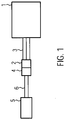
- Fig. 1 shows a schematic view of a medical monitoring system in which the connector system of the present invention can be applied.
- the monitoring system comprises a monitoring device 1 provided with a first connector 2 which is electrically connected to the monitoring device 1 by means of electrical signal and/or supply lines 3.
- the monitoring device 1 can transmit and receive electrical signals via the lines 3 to and from the first connector 2. Furthermore, the monitoring device 1 can apply a supply voltage via the lines 3.
- the first connector 2 can be releasably attached to a second connector 4 which is in electrical connection with a measurement component 5 such as a sensor, in particular a temperature sensor for detecting a temperature.
- a measurement component 5 such as a sensor, in particular a temperature sensor for detecting a temperature.
- the measurement component 5 might be a temperature sensor for sensing the body temperature of a patient which is to be monitored by the monitoring device 1.
- the temperature sensor other kinds of sensors, such as a pressure sensor and the like are applicable, too.
- the first connector 2 and the second connector 4 When the first connector 2 and the second connector 4 are coupled it is provided an electrical interconnection between the measurement component 5 and the monitoring device 1 in an appropriate manner, i.e. in a manner that allows the monitoring device 1 to operate the respective measurement component 5 e.g. by measuring a quantity to be measured.
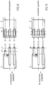
- FIG. 1 More detailed views of embodiments of the connector system comprising the first and the second connectors 2, 4 are shown in Figs 2 to 9 .
- the first and the second connector 2, 4 are provided with contact terminals A to G.
- the first connector 2 comprises first contact terminals E, F, G which are depicted for simplicity substantially adjacent to one another and are operable to provide contact on a plane 0L indicated by a dashed line crossing the first contact terminals E, F, G in Fig. 2 .
- the first contact terminals E, F, G are electrically connected with the monitoring device 1 via the electrical signal and/or supply lines 3.
- the second connector 4 comprises second contact terminals A, B, C, D.
- the second contact terminals A, B, C, D are provided in a different configuration.
- the first connector 2 is moved relative to the second connector 4 to couple the connectors 2, 4 by bringing corresponding ones of the first and second contact terminals into contact.
- the first contact terminal E comes in contact with the second contact terminal A
- the first contact terminal F comes in contact with the second contact terminal C
- the first contact terminal G comes in contact with the second contact terminal D.
- the second contact terminals A, C, D of the second connector 4 are in an arrangement which allows a contacting with the first contact terminals E, F, G of the first connector 2 which have a similar arrangement when connecting the connectors in the connecting direction CD.
- the contact terminals C and F as well as the contact terminals D and G comes into contact with each other, respectively.
- the monitoring device 1 cannot obtain a safe indication thereof whether the measurement component 5 connected is a measurement component which is allowed or capable to operate with the monitoring device 1. Therefore, measures for identification are included in the second connector 4 associated with the measurement component 5.
- the second connector 4 comprises two planes perpendicular to the connecting direction CD, a first connecting plane L1 and a second connecting plane L2. While in the first connecting plane L1 only the contact terminals A, C, D are contactable, in the second connecting plane L2 the contact terminals B, C, D are contactable.
- Contact terminal B is arranged beneath the contact terminal A in the connection direction CD such that contact terminal E contacts either contact terminal A or contact terminal B depending on the progress of the connecting movement.
- the contact terminals C and 0 are formed as long shaped contact terminals which extend form the first connecting plane L1 to the second connecting plane L2.
- the first contact terminals E, F, G are coupled with the second contact terminals A, C, D of the second connector 4 such that the contact terminals A and E, C and F and D and G comes into contact when the contact terminals E, F, G of the first connector 2 arrives at the first plane L1.
- the first connector 2 is further moved relative towards the second connector 4 such that the contact terminals E, F, G of the first connector 2 approaches the second connecting plane L2 and finally contacts the second contact terminals B, C, D provided at the second connecting plane L2.
- the connectors 2, 4 are fully connected.
- An interconnection between the measurement component and the monitoring device is then provided via the contact terminals C and F, D and G.
- the monitoring device 1 can identify the kind of measurement component 5 associated with the second connector 4 by detecting the changes of electrical states between signal and supply lines 3 while connecting the first and the second connectors 2, 4 until the final connecting position has been reached.
- a contact terminal E comes in contact with the contact terminal B of the second connector 4.
- the contact terminal A and the contact terminal C are interconnected by means of a first resistor R1 and the contact terminal B and the contact terminal C are interconnected with a second resistor R2.
- the resistors have different resistances.
- one or more of the resistors can be omitted thereby providing an infinite resistance between the respective contact terminals.
- the monitoring device 1 is sensing the resistance value between the contact terminals E and F via the respective signal lines 3 while the first connector 2 is being connected to the second connector 4.
- the monitoring 5 device 1 detects a change of the resistance from an infinite resistance (open circuit between the contact terminals E and F) to the resistance of R1 and while further connecting the connectors 2, 4 to the second connecting stage (arriving the second plane of the second connector) the detected resistance between E and F changes from the resistance value of R1 either directly to the resistance value of R2 or via a change to infinite resistance (open circuit) and thereafter from an infinite resistance to the resistance value of R2.
- the resistance profile obtained thereby and the predetermined resistance values of R1 and R2 clearly and uniquely identify the second connector 4 and consequently the measurement component 5 connected therewith.
- the monitoring device 1 may clearly identify what kind of measurement component 5 is attached.
- the monitoring device 1 can control the measurement component in an appropriate manner and the measurement values measured via the contact terminals F and G can be clearly and uniquely interpreted.
- each of the connectors 2 and 4 comprises four contact terminals.
- the first connector 2 comprises the contact terminals E, J, F, G and the second connector 4 comprises the contact terminals A, B, C, D.
- the contact terminals B, C, D of the second connector 4 are formed such they extend over the first connecting plane L1 and the second connecting plane L2.
- the contact terminal A is only contactable via the first connecting plane L1.
- the first resistance R1 is applied between the contact terminal A and the contact terminal C and the second resistance R2 is connected between the contact terminal B and the contact terminal C.
- the measurement component 5 is connected with the contact terminals C and D like in the embodiment of Fig. 2 .
- the monitoring device 1 therefore, experiences a change of the resistance between the contact terminals E and F from infinite resistance to the resistance of R2 and a change between the contact terminals J and F from infinite resistance to the resistance value of R1.
- the resistance changes are monitored and compared to a stored resistance profile indicating resistance changes to identify the measurement component associated with the second connector 4.
- the stored resistance profile indicates for each allowed second connector 4 a timely change of resistances between specific contact terminals of the first connector 2 and their respective resistance values.
- FIG. 4 A further embodiment of the connector system is shown in Fig. 4 .
- the connector system of Fig. 4 differs from the connector system as shown in Fig. 2 in that the contact terminal D of the second connector 4 is not present (contactable) in the first connecting plane L1 such that while connecting the first connector 2 and the second connector 4 an applying of the measurement component 5 to the monitoring device 1 is completed only when the connectors 2, 4 are fully coupled, i.e. the contact terminals of the first connector 2 have reached the second connecting plane L2 of the second connector 4.
- Fig. 5 an exemplary connector system is depicted.
- the contact terminals A, B are provided as a single contact terminal A which has an L-shape.
- the contact terminals E, F of the first connector 2 both contact the contact terminal A being thereby shortcut which can be detected by the monitoring device 1.
- the contact terminal F of the first connector 2 comes out of contact with the contact terminal A of the second connector 4 and comes into contact with contact terminal C of the second connector 4 while the contact terminal E of the first connector 2 remains in contact with the contact terminal A of the second connector 4.
- the resistance changes between contact terminals E, F are detected and compared to a stored resistance profile indicating resistance changes to identify the measurement component associated with the second connector 4.
- a timely change of an open loop, to a shortcut and back to an open loop between the contact terminals E, F can thereby be interpreted as a full coupling of the two connectors 2, 4.
- a further embodiment of a connector system is depicted.
- the contact terminal B of the second connector 4 can be contacted with the contact terminal E of the first connector 2 both in the first and the second connecting stage.
- the contact terminal C is only contactable by the contact terminal F of the first connector 2 in the second connecting stage and a contact terminal A is provided in the same connecting line before contact terminal C and is adapted to be contacted by the contact terminal F of the first connector 2 in the first connecting stage.
- a resistance R3 is provided between the contact terminal A and the contact terminal C a resistance R3 is provided.
- the monitoring device 1 detects in the first connecting stage via contact terminal F an electrical quantity which depends on the resistance value R3 and in the second connecting stage an electrical quantity which does not depend on the resistance value R3.
- a timely change resistance measurement via a contact terminal F does result in a resistance increased by R3 in the first connecting stage and in a resistance not increased by R3 in the following second resistance state.
- a further exemplary connector system is depicted.
- the contact terminals B, C, D of the second connector 4 can only be contacted with the respective contact terminals E, F, G of the first connector 2 in the second connecting stage.
- a common contact terminal A is provided which can be contacted by the contact terminals E, F, G substantially at the same time in the first connecting stage thereby providing a shortcut between all contact terminals E, F, G in the first connecting stage.
- the measurement component 5 is directly connected via the first and second connectors 2, 4 to the monitoring device 1 which can detect normal electrical characteristics (e.g. internal impedance) of the measurement component 5 not being influenced by a further electrical element, such as a resistance device or the like.
- the design of the connectors 2, 4 is substantially arbitrary. It is, however, essential that the first and the second connectors 2, 4 can be coupled with one another and that the connector associated with the measurement component 5 has at least two connecting planes including different arrangements of the plurality of respective contact terminals, wherein the contact terminals related to the different connecting planes are successively contacted while the connecting of the connectors progresses. Some of the second contact terminals are coupled with the measurement component 5 and other contact terminals have a connection with another of the contact terminals via a resistor or another passive electrical device.
- first contact terminals of the first connector 2 are preferably provided as sliding contacts.
- the second contact terminals of the second connector 4 are preferably provided as plane contact areas provided on a printed circuit board as a substrate or the like.
- the embodiments of Figs. 8 and 9 now provide that the first 5 connector 2 is configured as a socket and the second connector 4 configured as a plug.
- the socket of the first connector 2 has openings for receiving pins of the plug of the second connector 4.
- Inner walls of the openings 12 are provided with inner contact terminals 11 which correspond to the contact terminals E, F, G.
- the pins of the plug correspond to the second contact terminals A, C, D.
- the pins 13 have different lengths thereby defining different connecting planes as described above.
- the pins 13 of the contact terminals C and D have a first, longer length and the pin of the contact terminal A has a second shorter length thereby providing the different connecting planes L1 and L2. While connecting the plug and the socket the pins C and D firstly come into contact with the inner contact terminals 11 F and G of the socket and while further proceeding the connecting the shorter pin A comes into contact with the inner contact terminal E of the socket.
- the monitoring device 1 In the monitoring device 1, therefore, it is firstly detected the inner resistance of the measurement component between the contact terminals F and G and while further connecting the plug and the socket the resistance between the contact terminals E and F changes from infinite resistance to the resistance value of R1.
- the measurement component 5 associated with the plug can be clearly and uniquely be identified by determining the resistance profile while connecting the plug and the socket. Identification is defined by the value of the resistance R1 and the length of each of the pins A, C, D of the plug.
- the socket as the first connector 2 has openings wherein the inner contact terminals 12 are differently configured thereby providing different connecting planes L3 and L4 with respect to pins of a plug to be connected therewith. While the openings 12 of the contact terminals F and G have an inner contact terminal which can be contacted when the connecting of the pins has reached a first connecting plane L3 of the socket, the contact terminal E is recessed in the respective opening such that the respective pin of the plug can only contact when reached the second connecting plane L4. Thereby, while connecting, a respective pin A of the plug will contact the contact terminal E at a later point of time than the time the pin C and D contact the contact terminals F and G, respectively.
- resistances R1, R2 instead of resistances R1, R2 other kinds of electrical passive devices such as capacities or inductors, or active devices such as transistors and the like can be provided to provide electrically measurable quantities between the respective contact terminals.
- the electric quantities such as an impedance can e.g. be measured by applying an AC signal via the respective signal lines.
- the number of connecting planes in the second connector is not limited to two but can also be more than two.
- the number of electrical devices for providing the electrical quantity is not limited to one or two.
- the inner resistance of the measurement component 5 can be used as one of the resistances to be checked between the respective contact terminals to identify the measurement component.
- a monitoring device 1 including an identification unit 16 for identifying the kind of measurement component 5 connected with the first connector 2.
- the identification unit 16 comprises a measurement unit 17or detecting the resistance values between the different signal lines and for establishing a time-resistance characteristics of the resistances values and its variations in time and comparing such a time-resistance characteristics by means of a comparing unit 18 with profiles prestored in a appropriate memory unit 19.
- An identification information is output by the comparing unit 18 to a monitoring unit 20 of the monitoring device which is connected to the signal lines 3 reserved for being operatively connected to the measurement component 5.
- the measurement is performed by the monitoring unit 20 depending on the identification information identifying the respective measurement component 5 connected.
Landscapes
- Physics & Mathematics (AREA)
- General Physics & Mathematics (AREA)
- Testing Of Short-Circuits, Discontinuities, Leakage, Or Incorrect Line Connections (AREA)
- Details Of Connecting Devices For Male And Female Coupling (AREA)
Description
- The present invention is related to the field of connectors for appliances, in particular for medical use.
- IBM technical disclosure bulletin, vol. 36, no. 2, March 1993, page 199 discloses a connector and an electrical component arrangement according to the preamble of the independent claims 1 and 7.
- In medical monitoring systems one or more electronic components, such as a measurement equipment, actuator equipment and the like, are connected with a base station, such as a monitoring device, a control unit and the like, to provide a specific functionality. In practice, it is often the case that measurement equipment such as a sensor and the like is connected to a monitoring device or another measurement unit which use the measurement equipment to obtain measurement values to be monitored in the monitoring device. Usually, such a monitoring device is operable with a plurality of different sensors or other devices. Further, it might be possible that any measurement equipment can be connected to the monitoring device which might be not configured to be operated therewith. Therefore, there is a need that the monitoring device gets an indication about whether a correct measurement equipment is connected and furthermore what kind of measurement equipment is connected. Thereby, measurement failures resulting in wrong interpretation of measurement results, electrical shortcuts and damage of the electrical equipment could be avoided.
- Since the measurement equipment often comprises disposable components and due to its small size it is not appropriate to equip the disposable measurement sensor with any processor or similar expensive electronic parts which allow a unique identification of the measurement equipment in the monitoring device. Furthermore, there is a need that the measurement equipment is kept as small as possible.
- A conventional solution to assure that the monitoring device is connected to a correct measurement device is to realize a specific geometry of a plug which only fits to a corresponding socket and vice versa. Other measurement components then provide other shapes of plugs thereby being incapable to be connected with the monitoring device. Another known approach is to arrange pins of the plug in a specific arrangement such that the pins of the plug and the respective contact terminals of the socket have to be in correspondence to enable a correct coupling.
- Moreover, in case that different kinds of measurement components are to be connected with one monitoring device depending on the intended use the connector geometry associated with the monitoring device has to be adapted to match with different kinds of connectors associated with the respective measurement component. There still remains the issue that the monitoring device should be informed about which kind of measurement component has been connected.
- It is therefore an object of the present invention to provide a connector system for connecting an electrical component to a base station wherein the connector system provides a protection against erroneous connecting of an incorrect electrical component which is not appropriate to operate with the base station. It is a further object of the present invention to provide that the connector system avoids the implementing of expensive electronic parts or any processing device within the electrical component in particular in case the electrical component is disposable which is often the case in medical appliances. Furthermore, it is object of the present invention that in case that different components are capable to function with the base station the electrical component connected can be identified during the connecting process without modifying the electrical component to be connected or to manually input respective data in the base station.
- These objects are achieved by the connector according to claim 1, a connector system, an electrical component arrangement, an electrical component arrangement comprising a monitoring device and a method for operating an electrical component according to the further independent claims.
- Further embodiments of the present invention are defined in the depending subclaims.
- According to a first aspect a second connector suitable for being coupled to a first connector is provided. The first connector is suitable for coupling a monitoring device and having a plurality of first contact terminals, and the second connector is suitable for coupling an electrical component and having a plurality of second contact terminals. Between at least two of the plurality of second contact terminals an electrical device is arranged for providing a detectable electrical quantity. The first and second connectors are capable of being coupled in a connecting process in a connecting direction. The second contact terminals and the electrical device are arranged such that a first subset of second contact terminals is contactable in a first connecting plane perpendicular to the connecting direction and second subset of second contact terminals different from the first subset is contactable in a second connecting plane perpendicular to the connecting direction. While connecting, the first contact terminals come into contact with the first subset of the plurality of second contact terminals in a first connecting stage and while the connecting further proceeds the first contact terminals come into contact with the second subset of the second contact terminals, such that in the first connecting stage a first electrical quantity provided in the first connecting stage between two of the first contact terminals is detectable which is different from the electrical quantity in an uncoupled condition of the connectors, and in the second connecting stage a second electrical quantity provided in the second connecting stage between two of the first contact terminals is detectable which is different from the electrical quantity detected in the first connecting stage. The first or second electrical quantity is provided by the electrical device.
- Furthermore, the electrical device may be at least one of a resistor, a capacity and an inductivity.
- According to an embodiment, the second connector may be configured to provide two second contact terminals wherein one of the two second contact terminals being contactable by a respective one of the first contact terminals in the first connecting stage and the other of the two second contact terminals is contactable by the respective one first contact terminal in the second connecting stage.
- The two second contact terminals may be each coupled with one electrical device and are spaced such that, while connecting, the one first contact terminal is isolated from the two second contact terminals between the first and the second connecting stages.
- According to a further aspect an electrical component arrangement is provided comprising an electrical component and a connector coupled with the electrical component. The connector having a plurality of contact terminals, wherein between at least two of the plurality of contact terminals an electrical device is arranged for providing a detectable electrical quantity. A first subset of the plurality of contact terminals is arranged to be contactable in a first connecting stage and a second subset of the contact terminals is arranged to be contactable in a second connecting stage, such that, when contacting the first subset of the contact terminals in the first connecting plane an electrical quantity between two of the contact terminals is detectable, and when contacting the second subset of the contact terminals in the second connecting stage a further electrical quantity between two of the contact terminals is detectable which is different from the electrical quantity detected between the respective two of the contact terminals in the first connecting plane.
- According to an embodiment one of the electrical quantities detectable in the first connecting plane and/or the second connecting plane is provided by the electrical component.
- According to a further aspect an electrical component arrangement comprising a monitoring device for coupling to an electrical component by means of a connector is provided. The monitoring device is adapted to identify the kind of measurement component connected with the first connector and comprises an identification unit for sensing timely characteristics of electrical quantities on signal lines coupled to the connector, a comparing unit for comparing the sensed timely characteristics of the electrical quantities with a prestored electrical quantity profile, and a monitoring unit for operating the electrical component via the connector depending on the result of the comparing of the comparing unit.
- According to a further aspect a method for operating an electrical component via a connector is provided, comprising the steps of sensing timely characteristics of an electrical quantity on signal lines coupled to the connector, of comparing the sensed timely characteristics of the electrical quantity with a prestored electrical quantity profile, and of operating the electrical component via the connector depending on the result of the step of comparing.
- Preferred embodiments of the present invention are explained in detail in conjunction with the accompanying drawings in which:
-
Fig. 1 is a general schematic view of a monitoring system according to a first embodiment of the present invention; -
Fig. 2 is a schematic view of an arrangement of contact terminals in a first and a second connector of the connector system according to the present invention; -
Fig. 3 is a schematic view of an arrangement of contact terminals of first and second connectors of a connector system according to a further embodiment of the present invention; -
Fig. 4 is a schematic view of an arrangement of contact terminals of first and second connectors of a connector system according to a further embodiment of the present invention; -
Fig. 5 is a schematic view of an arrangement of contact terminals of first and second connectors of an exemplary connector system; -
Fig. 6 is a schematic view of an arrangement of contact terminals of first and second connectors of a connector system according to a further embodiment of the present invention; -
Fig. 7 is a schematic view of an arrangement of contact terminals of first and second connectors of a further exemplary connector; -
Fig. 8 is a schematic view of a plug and a socket of a connector system according to a further embodiment of the present invention; -
Fig. 9 is a schematic view of a plug and a socket of a connector system according to a background example; and -
Fig. 10 is a block diagram showing a monitoring device according to a further aspect. - Like reference numbers indicate elements having a same or a similar functionality.
-
Fig. 1 shows a schematic view of a medical monitoring system in which the connector system of the present invention can be applied. The monitoring system comprises a monitoring device 1 provided with afirst connector 2 which is electrically connected to the monitoring device 1 by means of electrical signal and/orsupply lines 3. The monitoring device 1 can transmit and receive electrical signals via thelines 3 to and from thefirst connector 2. Furthermore, the monitoring device 1 can apply a supply voltage via thelines 3. - The
first connector 2 can be releasably attached to asecond connector 4 which is in electrical connection with ameasurement component 5 such as a sensor, in particular a temperature sensor for detecting a temperature. Preferably, as the monitoring system is used in a medical environment themeasurement component 5 might be a temperature sensor for sensing the body temperature of a patient which is to be monitored by the monitoring device 1. Instead of the temperature sensor other kinds of sensors, such as a pressure sensor and the like are applicable, too. - When the
first connector 2 and thesecond connector 4 are coupled it is provided an electrical interconnection between themeasurement component 5 and the monitoring device 1 in an appropriate manner, i.e. in a manner that allows the monitoring device 1 to operate therespective measurement component 5 e.g. by measuring a quantity to be measured. - More detailed views of embodiments of the connector system comprising the first and the
second connectors Figs 2 to 9 . - In
Fig. 2 the first and thesecond connector first connector 2 comprises first contact terminals E, F, G which are depicted for simplicity substantially adjacent to one another and are operable to provide contact on a plane 0L indicated by a dashed line crossing the first contact terminals E, F, G inFig. 2 . The first contact terminals E, F, G are electrically connected with the monitoring device 1 via the electrical signal and/orsupply lines 3. - The
second connector 4 comprises second contact terminals A, B, C, D. The second contact terminals A, B, C, D are provided in a different configuration. As indicated by the connecting direction indicated by the arrow CD, thefirst connector 2 is moved relative to thesecond connector 4 to couple theconnectors second connector 4 are in an arrangement which allows a contacting with the first contact terminals E, F, G of thefirst connector 2 which have a similar arrangement when connecting the connectors in the connecting direction CD. - To provide an electrical connection between the
measurement component 5 and the monitoring device 1 it is sufficient that the contact terminals C and F as well as the contact terminals D and G comes into contact with each other, respectively. However, the monitoring device 1 cannot obtain a safe indication thereof whether themeasurement component 5 connected is a measurement component which is allowed or capable to operate with the monitoring device 1. Therefore, measures for identification are included in thesecond connector 4 associated with themeasurement component 5. - The
second connector 4 comprises two planes perpendicular to the connecting direction CD, a first connecting plane L1 and a second connecting plane L2. While in the first connecting plane L1 only the contact terminals A, C, D are contactable, in the second connecting plane L2 the contact terminals B, C, D are contactable. Contact terminal B is arranged beneath the contact terminal A in the connection direction CD such that contact terminal E contacts either contact terminal A or contact terminal B depending on the progress of the connecting movement. The contact terminals C and 0 are formed as long shaped contact terminals which extend form the first connecting plane L1 to the second connecting plane L2. - While performing the connecting of the first and the
second connectors second connector 4 such that the contact terminals A and E, C and F and D and G comes into contact when the contact terminals E, F, G of thefirst connector 2 arrives at the first plane L1. While the connecting progresses, thefirst connector 2 is further moved relative towards thesecond connector 4 such that the contact terminals E, F, G of thefirst connector 2 approaches the second connecting plane L2 and finally contacts the second contact terminals B, C, D provided at the second connecting plane L2. - When the contact terminals E, F, G of the
first connector 2 arrives at the contact terminals B, C, D of thesecond connector 4 theconnectors measurement component 5 associated with thesecond connector 4 by detecting the changes of electrical states between signal andsupply lines 3 while connecting the first and thesecond connectors Fig. 2 while connecting the contact terminal E firstly comes in contact with the contact terminal A of thesecond connector 4 and thereafter while further proceeding the connecting process a contact terminal E comes in contact with the contact terminal B of thesecond connector 4. - In the
second connector 4 the contact terminal A and the contact terminal C are interconnected by means of a first resistor R1 and the contact terminal B and the contact terminal C are interconnected with a second resistor R2. Preferably, the resistors have different resistances. Optionally one or more of the resistors can be omitted thereby providing an infinite resistance between the respective contact terminals. The monitoring device 1 is sensing the resistance value between the contact terminals E and F via therespective signal lines 3 while thefirst connector 2 is being connected to thesecond connector 4. When the contact terminals E and F comes into contact with the contact terminals A and C, respectively, themonitoring 5 device 1 detects a change of the resistance from an infinite resistance (open circuit between the contact terminals E and F) to the resistance of R1 and while further connecting theconnectors second connector 4 and consequently themeasurement component 5 connected therewith. As a consequence, the monitoring device 1 may clearly identify what kind ofmeasurement component 5 is attached. In the following the monitoring device 1 can control the measurement component in an appropriate manner and the measurement values measured via the contact terminals F and G can be clearly and uniquely interpreted. - In
Fig. 3 a further embodiment of a connector system is depicted. In contrast to the embodiment ofFig. 2 each of theconnectors first connector 2 comprises the contact terminals E, J, F, G and thesecond connector 4 comprises the contact terminals A, B, C, D. The contact terminals B, C, D of thesecond connector 4 are formed such they extend over the first connecting plane L1 and the second connecting plane L2. The contact terminal A is only contactable via the first connecting plane L1. The first resistance R1 is applied between the contact terminal A and the contact terminal C and the second resistance R2 is connected between the contact terminal B and the contact terminal C. Themeasurement component 5 is connected with the contact terminals C and D like in the embodiment ofFig. 2 . While connecting the contact terminals E, J, F, G firstly come into contact with the respective corresponding contact terminals B, A, C, D, of the first connecting plane L1 of thesecond connector 4, such that the monitoring device 1 can detect the resistance value of R1 between the contact terminals J and F and the resistance value of R2 between the contact terminals E and F. The monitoring device 1, therefore, experiences a change of the resistance between the contact terminals E and F from infinite resistance to the resistance of R2 and a change between the contact terminals J and F from infinite resistance to the resistance value of R1. While further proceeding the connecting process the contact terminal J comes out of contact to the contact terminal A of thesecond connector 4 such that the resistance changes from R1 to infinite resistance. - In the monitoring device 1 the resistance changes are monitored and compared to a stored resistance profile indicating resistance changes to identify the measurement component associated with the
second connector 4. The stored resistance profile indicates for each allowed second connector 4 a timely change of resistances between specific contact terminals of thefirst connector 2 and their respective resistance values. - A further embodiment of the connector system is shown in
Fig. 4 . The connector system ofFig. 4 differs from the connector system as shown inFig. 2 in that the contact terminal D of thesecond connector 4 is not present (contactable) in the first connecting plane L1 such that while connecting thefirst connector 2 and thesecond connector 4 an applying of themeasurement component 5 to the monitoring device 1 is completed only when theconnectors first connector 2 have reached the second connecting plane L2 of thesecond connector 4. This allows to have a further feature for identifying therespective measurement component 5 in that the monitoring device 1 can determine by sensing the resistance between the contact terminals F and G an infinite resistance in a first connecting plane L1 when the resistance value of R1 is detected between contact terminals E and F and in the second connecting plane L2 the internal resistance of themeasurement component 5 can be detected between the contact terminals F and G such that the further feature is provided for identifying themeasurement component 5. - In
Fig. 5 an exemplary connector system is depicted. In contrast to the embodiment ofFig. 2 no resistances have to be provided on the substrate of thefirst connector 2. The contact terminals A, B are provided as a single contact terminal A which has an L-shape. In the first connecting stage the contact terminals E, F of thefirst connector 2 both contact the contact terminal A being thereby shortcut which can be detected by the monitoring device 1. While further connecting the twoconnectors first connector 2 comes out of contact with the contact terminal A of thesecond connector 4 and comes into contact with contact terminal C of thesecond connector 4 while the contact terminal E of thefirst connector 2 remains in contact with the contact terminal A of thesecond connector 4. - In the monitoring device 1 the resistance changes between contact terminals E, F are detected and compared to a stored resistance profile indicating resistance changes to identify the measurement component associated with the
second connector 4. A timely change of an open loop, to a shortcut and back to an open loop between the contact terminals E, F can thereby be interpreted as a full coupling of the twoconnectors - In
Fig. 6 a further embodiment of a connector system is depicted. In contrast to the embodiment ofFig. 2 the contact terminal B of thesecond connector 4 can be contacted with the contact terminal E of thefirst connector 2 both in the first and the second connecting stage. Further, the contact terminal C is only contactable by the contact terminal F of thefirst connector 2 in the second connecting stage and a contact terminal A is provided in the same connecting line before contact terminal C and is adapted to be contacted by the contact terminal F of thefirst connector 2 in the first connecting stage. Between the contact terminal A and the contact terminal C a resistance R3 is provided. Thereby, the monitoring device 1 detects in the first connecting stage via contact terminal F an electrical quantity which depends on the resistance value R3 and in the second connecting stage an electrical quantity which does not depend on the resistance value R3. In one example a timely change resistance measurement via a contact terminal F does result in a resistance increased by R3 in the first connecting stage and in a resistance not increased by R3 in the following second resistance state. - In
Fig. 7 a further exemplary connector system is depicted. In contrast to the embodiment ofFig. 2 the contact terminals B, C, D of thesecond connector 4 can only be contacted with the respective contact terminals E, F, G of thefirst connector 2 in the second connecting stage. A common contact terminal A is provided which can be contacted by the contact terminals E, F, G substantially at the same time in the first connecting stage thereby providing a shortcut between all contact terminals E, F, G in the first connecting stage. In the second connecting stage themeasurement component 5 is directly connected via the first andsecond connectors measurement component 5 not being influenced by a further electrical element, such as a resistance device or the like. - In the embodiments of
Figs. 2 to 7 it has been intentionally left open how the first and thesecond connectors connectors second connectors measurement component 5 has at least two connecting planes including different arrangements of the plurality of respective contact terminals, wherein the contact terminals related to the different connecting planes are successively contacted while the connecting of the connectors progresses. Some of the second contact terminals are coupled with themeasurement component 5 and other contact terminals have a connection with another of the contact terminals via a resistor or another passive electrical device. - In one embodiment, the first contact terminals of the
first connector 2 are preferably provided as sliding contacts. The second contact terminals of thesecond connector 4 are preferably provided as plane contact areas provided on a printed circuit board as a substrate or the like. - The embodiments of
Figs. 8 and 9 now provide that the first 5connector 2 is configured as a socket and thesecond connector 4 configured as a plug. The socket of thefirst connector 2 has openings for receiving pins of the plug of thesecond connector 4. Inner walls of theopenings 12 are provided withinner contact terminals 11 which correspond to the contact terminals E, F, G. The pins of the plug correspond to the second contact terminals A, C, D. Thepins 13 have different lengths thereby defining different connecting planes as described above. Thepins 13 of the contact terminals C and D have a first, longer length and the pin of the contact terminal A has a second shorter length thereby providing the different connecting planes L1 and L2. While connecting the plug and the socket the pins C and D firstly come into contact with the inner contact terminals 11 F and G of the socket and while further proceeding the connecting the shorter pin A comes into contact with the inner contact terminal E of the socket. - In the monitoring device 1, therefore, it is firstly detected the inner resistance of the measurement component between the contact terminals F and G and while further connecting the plug and the socket the resistance between the contact terminals E and F changes from infinite resistance to the resistance value of R1. Thereby, the
measurement component 5 associated with the plug can be clearly and uniquely be identified by determining the resistance profile while connecting the plug and the socket. Identification is defined by the value of the resistance R1 and the length of each of the pins A, C, D of the plug. - Additionally or optionally, as shown in
Fig. 9 , it can be provided that the socket, as thefirst connector 2 has openings wherein theinner contact terminals 12 are differently configured thereby providing different connecting planes L3 and L4 with respect to pins of a plug to be connected therewith. While theopenings 12 of the contact terminals F and G have an inner contact terminal which can be contacted when the connecting of the pins has reached a first connecting plane L3 of the socket, the contact terminal E is recessed in the respective opening such that the respective pin of the plug can only contact when reached the second connecting plane L4. Thereby, while connecting, a respective pin A of the plug will contact the contact terminal E at a later point of time than the time the pin C and D contact the contact terminals F and G, respectively. - Instead of resistances R1, R2 other kinds of electrical passive devices such as capacities or inductors, or active devices such as transistors and the like can be provided to provide electrically measurable quantities between the respective contact terminals. The electric quantities such as an impedance can e.g. be measured by applying an AC signal via the respective signal lines.
- Furthermore, the number of connecting planes in the second connector is not limited to two but can also be more than two. As well the number of electrical devices for providing the electrical quantity is not limited to one or two. Moreover, the inner resistance of the
measurement component 5 can be used as one of the resistances to be checked between the respective contact terminals to identify the measurement component. - In
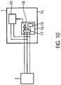
Fig. 10 a monitoring device 1 is depicted including anidentification unit 16 for identifying the kind ofmeasurement component 5 connected with thefirst connector 2. Theidentification unit 16 comprises a measurement unit 17or detecting the resistance values between the different signal lines and for establishing a time-resistance characteristics of the resistances values and its variations in time and comparing such a time-resistance characteristics by means of a comparingunit 18 with profiles prestored in aappropriate memory unit 19. An identification information is output by the comparingunit 18 to amonitoring unit 20 of the monitoring device which is connected to thesignal lines 3 reserved for being operatively connected to themeasurement component 5. The measurement is performed by themonitoring unit 20 depending on the identification information identifying therespective measurement component 5 connected.
Claims (8)
- A second connector (4) suitable for being coupled to a first connector (2);- said first connector (2) being suitable for coupling a monitoring device (1) and having a plurality of first contact terminals (E, F, G, J) arranged substantially adjacent to one another and being operable to provide contact in a plane (0L);- the second connector (4) being suitable for coupling to an electrical component (5) and having a plurality of second contact terminals (A, B, C, D),wherein, between at least two of the plurality of second contact terminals (A, B, C, D), an electrical device (R1, R2) is arranged for providing a detectable electrical quantity;
wherein the first and second connectors (2, 4) are capable of being coupled in a connecting process in a connecting direction (CD);
characterized in that the second contact terminals (A, B, C, D) and the electrical device (R1, R2) are arranged such that a first subset (A, C, D; A, B, C, D; A, C; A, B, D; C, D) of second contact terminals (A, B, C, D) is contactable in a first connecting plane (L1) perpendicular to the connecting direction (CD) and a second subset (B, C, D; A, C, D) of second contact terminals (A, B, C, D) different from the first subset is contactable in a second connecting plane (L2) perpendicular to the connecting direction (CD), and such that, while connecting, the first contact terminals (E, F, G, J) come into contact with the first subset (A, C, D; A, B, C, D; A, C; A, B, D; C, D) of the plurality of second contact terminals (A, B, C, D) in a first connecting stage, in which the first contact terminals (E, F, G, J) of the first connector (2) are positioned in the first connecting plane (L1), and while the connecting further proceeds the first contact terminals (E, F, G, J) come into contact with the second subset (B, C, D; A, C, D) of the second contact terminals (A, B, C, D) in a second connecting stage, in which the first contact terminals (E, F, G, J) of the first connector (2) are positioned in the second connecting plane (L2), and
in that a first electrical quantity provided in the first connecting stage between two of the first contact terminals (E, F, G, J), which is different from an electrical quantity between said two of the first contact terminals (E, F, G, J) in an uncoupled condition of the connectors (2, 4), and a second electrical quantity provided in the second connecting stage between at least two of the first contact terminals (E, F, G, J), which is different from the first electrical quantity in the first connecting stage, are detectable by the monitoring device (1) coupled to the first connector (2),
and in that the first or second detectable electrical quantity is provided by the electrical device (R1, R2). - A connector system comprising:a first connector (2) suitable for coupling to a monitoring device (1) and having a plurality of first contact terminals (E, F, G, J) arranged substantially adjacent to one another and being operable to provide contact in a plane (0L); anda second connector (4) according to claim 1;wherein the first and second connectors (2, 4) are capable of being coupled in a connecting process in the connecting direction (CD).
- The connector system of claim 2, wherein the electrical device (R1, R2) is at least one of a resistor, a capacity and an inductivity.
- The connector system of claim 2, wherein the second connector (4) is configured to provide two of the second contact terminals (A, B; A, C) such that one (A) of the two second contact terminals (A, B; A, C) is contactable by a respective one (E; F) of the first contact terminals (E, F, G, J) in the first connecting stage and the other (B; C) of the two second contact terminals (A, B; A, C) is contactable by the respective one first contact terminal (E; F) in the second connecting stage.
- The connector system of claim 4, wherein the two second contact terminals (A, B, C, D) are each coupled with one electrical device (R1, R2) and are spaced such that, while connecting, the one first contact terminal (E) is isolated from the two second contact terminals (A, B) between the first and the second connecting stages.
- An electrical component arrangement comprising an electrical component (5) and the second connector (4) according to claim 1 coupled with the electrical component (5).
- An electrical component arrangement comprising a monitoring device (1) for coupling to an electrical component and a first connector (2) coupled to the monitoring device (1) by signal lines (3), wherein the first connector (2) is suitable for being coupled to a second connector (4) according to claim 1, the first connector (2) having a plurality of first contact terminals (E, F, G, J) arranged substantially adjacent to one another and being operable to provide contact in a plane (0L), characterized in that the monitoring device (1) is adapted to identify the kind of measurement component (5) connected with the first connector (2) and comprises:- an identification unit (16) for sensing timely characteristics of an electrical quantity between the signal lines (3) coupled to the first connector (2);- a comparing unit (18) for comparing the sensed timely characteristics of the electrical quantity with a prestored profile;- a monitoring unit (20) for operating the electrical component (5) via the first connector (2), depending on the result of the comparing of the comparing unit (18).
- A method for operating an electrical component (5) via a first connector (2) and a second connector (4) according to claim 1, comprising the steps of:- connecting the first connector (2) to the second connector (4), said second connector (4) being coupled with the electrical component (5),- sensing timely characteristics of electrical quantities on signal lines (3) coupled to the first connector (2);- comparing the sensed timely characteristics of the electrical quantities with a prestored profile;- operating the electrical component (5) via the first connector (2) depending on the result of the step of comparing.
Applications Claiming Priority (2)
| Application Number | Priority Date | Filing Date | Title |
|---|---|---|---|
| DE102007022210A DE102007022210B3 (en) | 2007-05-11 | 2007-05-11 | Multi-level connector system for medical use |
| PCT/EP2008/003625 WO2008138515A1 (en) | 2007-05-11 | 2008-05-06 | Multilevel connector system |
Publications (2)
| Publication Number | Publication Date |
|---|---|
| EP2147486A1 EP2147486A1 (en) | 2010-01-27 |
| EP2147486B1 true EP2147486B1 (en) | 2021-01-06 |
Family
ID=39563587
Family Applications (1)
| Application Number | Title | Priority Date | Filing Date |
|---|---|---|---|
| EP08749347.4A Active EP2147486B1 (en) | 2007-05-11 | 2008-05-06 | Multilevel connector system |
Country Status (6)
| Country | Link |
|---|---|
| US (2) | US8597048B2 (en) |
| EP (1) | EP2147486B1 (en) |
| CN (1) | CN101785154B (en) |
| CA (1) | CA2687152A1 (en) |
| DE (1) | DE102007022210B3 (en) |
| WO (1) | WO2008138515A1 (en) |
Families Citing this family (7)
| Publication number | Priority date | Publication date | Assignee | Title |
|---|---|---|---|---|
| DE102009029042B4 (en) * | 2009-08-31 | 2015-05-28 | Endress + Hauser Gmbh + Co. Kg | Measuring device for determining at least one physical, chemical, or biological process variable of a medium |
| US20130017732A1 (en) * | 2011-01-15 | 2013-01-17 | Parke Eugene James | Method and apparatus for detecting improper connector seating or engagement |
| DE102014007637A1 (en) * | 2014-05-15 | 2015-11-19 | e.solutions GmbH | Electrical connection device |
| EP3345169A1 (en) * | 2015-09-01 | 2018-07-11 | Philips Lighting Holding B.V. | A system and method for monitoring the connection of a pluggable lighting unit to a socket |
| US9935668B1 (en) | 2017-02-16 | 2018-04-03 | Datron World Communications, Inc. | Detachment mechanism and indicator for mobile mount portable radio and method for the same |
| DE102017002547B3 (en) * | 2017-03-16 | 2018-02-22 | Drägerwerk AG & Co. KGaA | Device for the electrically conductive contacting of a hot wire sensor and medical device with such a device |
| US11637392B2 (en) * | 2020-01-07 | 2023-04-25 | Hamilton Sundstrand Corporation | Electrical mating systems |
Family Cites Families (18)
| Publication number | Priority date | Publication date | Assignee | Title |
|---|---|---|---|---|
| JPH01132076U (en) | 1988-03-04 | 1989-09-07 | ||
| US4949035A (en) * | 1989-01-06 | 1990-08-14 | Digital Equipment Corporation | Connector alignment verification and monitoring system |
| US5203004A (en) * | 1990-01-08 | 1993-04-13 | Tandem Computers Incorporated | Multi-board system having electronic keying and preventing power to improperly connected plug-in board with improperly configured diode connections |
| US5146172A (en) * | 1990-08-15 | 1992-09-08 | Sundstrand Corp. | Engine identification system |
| JPH0454162U (en) * | 1990-09-14 | 1992-05-08 | ||
| US5336934A (en) | 1992-12-17 | 1994-08-09 | Ford Motor Company | Electrical connection and interlock circuit system for vehicle electric drive |
| JPH0757062A (en) * | 1993-06-30 | 1995-03-03 | Ricoh Co Ltd | Electronic equipment |
| SE9402297D0 (en) | 1994-06-29 | 1994-06-29 | Siemens Elema Ab | indicating device |
| TW281724B (en) * | 1995-03-06 | 1996-07-21 | Advanced Micro Devices Inc | Apparatus and method to uniquely identify similarly connected electrical devices |
| RU2150744C1 (en) * | 1995-03-22 | 2000-06-10 | Фраматом Коннектор Энтернасьональ | Device for reading card with embedded chip |
| JPH0917510A (en) * | 1995-06-29 | 1997-01-17 | Sumitomo Wiring Syst Ltd | Fitting detection connector |
| DE19631425A1 (en) * | 1996-08-06 | 1998-02-12 | Wolf & Beck Gmbh Dr | Identification method for interchangeable accessories of machines tools |
| US6517375B2 (en) * | 2000-01-25 | 2003-02-11 | Compaq Information Technologies Group, L.P. | Technique for identifying multiple circuit components |
| US6411053B1 (en) * | 2000-09-26 | 2002-06-25 | Penny & Giles Drives Technology Limited | Electrical system |
| US6986071B2 (en) * | 2002-02-01 | 2006-01-10 | Powerdsine, Ltd. | Detecting network power connection status using AC signals |
| US20030146764A1 (en) | 2002-02-05 | 2003-08-07 | Chun-Liang Lee | Protector for blade module of information processing apparatus |
| CN1211893C (en) * | 2002-03-20 | 2005-07-20 | 建碁股份有限公司 | Circuit board with protection function and method for protecting circuit |
| US7985330B2 (en) * | 2005-12-30 | 2011-07-26 | Medtronic Minimed, Inc. | Method and system for detecting age, hydration, and functional states of sensors using electrochemical impedance spectroscopy |
-
2007
- 2007-05-11 DE DE102007022210A patent/DE102007022210B3/en active Active
-
2008
- 2008-05-05 US US12/599,473 patent/US8597048B2/en active Active
- 2008-05-06 EP EP08749347.4A patent/EP2147486B1/en active Active
- 2008-05-06 CN CN2008800230839A patent/CN101785154B/en active Active
- 2008-05-06 WO PCT/EP2008/003625 patent/WO2008138515A1/en active Application Filing
- 2008-05-06 CA CA002687152A patent/CA2687152A1/en not_active Abandoned
-
2013
- 2013-12-02 US US14/094,615 patent/US20140239937A1/en not_active Abandoned
Non-Patent Citations (1)
| Title |
|---|
| None * |
Also Published As
| Publication number | Publication date |
|---|---|
| US8597048B2 (en) | 2013-12-03 |
| CN101785154A (en) | 2010-07-21 |
| CA2687152A1 (en) | 2008-11-20 |
| CN101785154B (en) | 2013-11-13 |
| DE102007022210B3 (en) | 2008-12-18 |
| US20140239937A1 (en) | 2014-08-28 |
| EP2147486A1 (en) | 2010-01-27 |
| WO2008138515A1 (en) | 2008-11-20 |
| US20110199095A1 (en) | 2011-08-18 |
Similar Documents
| Publication | Publication Date | Title |
|---|---|---|
| US20140239937A1 (en) | Multilevel Connector System For Medical Use | |
| US8556659B1 (en) | Receptacle connector with circuitry for determining the configuration of a corresponding plug connector mated therewith | |
| US20170138986A1 (en) | Device for measuring at least one physical quantity of an electric installation | |
| KR20160075310A (en) | Automatic data bus wire integrity verification device | |
| EP3582996A1 (en) | Thermal management of electric vehicle coupler contacts | |
| CN110595524B (en) | Sensor saturation fault detection | |
| KR20070121720A (en) | Sensor system | |
| CN103792398A (en) | Error-prevention universal circuit board testing adapter | |
| CN112291108B (en) | Method for detecting network port connection state in Ethernet switch | |
| EP2921242B1 (en) | Press fitting | |
| CN207456645U (en) | Temperature transmitter and temperature transmitter component | |
| US20110167919A1 (en) | Vacuum measuring device with interchangeable sensors | |
| CN217112603U (en) | Test circuit board and test mechanism | |
| EP3385726A1 (en) | Kelvin connection with positional accuracy | |
| US10996308B2 (en) | Apparatus and method for authentication of electronic device test stations | |
| KR101002573B1 (en) | Apparatus for diagnosis of slot | |
| KR100858725B1 (en) | Apparatus and method for measuring insertion force of connectors | |
| JPH0275087A (en) | Magnetic line sensor | |
| US20080024139A1 (en) | Device and a Method for Testing At Least One Conductive Joint Forming an Electrical Connection Between an Electrical Component and a Printed Circuit | |
| CN117147988A (en) | Tester, test system and method for testing electrical components | |
| WO1989010639A1 (en) | Static-free interrogating connector for electric components | |
| KR200225512Y1 (en) | Device of Signal Line Error Detection for Circuit Board Assembly | |
| JP6733199B2 (en) | Inspection device, inspection method, and inspection program | |
| CN117665530A (en) | Detection circuit | |
| KR20010061435A (en) | Multi line cable checking device |
Legal Events
| Date | Code | Title | Description |
|---|---|---|---|
| PUAI | Public reference made under article 153(3) epc to a published international application that has entered the european phase |
Free format text: ORIGINAL CODE: 0009012 |
|
| 17P | Request for examination filed |
Effective date: 20091211 |
|
| AK | Designated contracting states |
Kind code of ref document: A1 Designated state(s): AT BE BG CH CY CZ DE DK EE ES FI FR GB GR HR HU IE IS IT LI LT LU LV MC MT NL NO PL PT RO SE SI SK TR |
|
| AX | Request for extension of the european patent |
Extension state: AL BA MK RS |
|
| DAX | Request for extension of the european patent (deleted) | ||
| 17Q | First examination report despatched |
Effective date: 20110713 |
|
| STAA | Information on the status of an ep patent application or granted ep patent |
Free format text: STATUS: EXAMINATION IS IN PROGRESS |
|
| GRAP | Despatch of communication of intention to grant a patent |
Free format text: ORIGINAL CODE: EPIDOSNIGR1 |
|
| STAA | Information on the status of an ep patent application or granted ep patent |
Free format text: STATUS: GRANT OF PATENT IS INTENDED |
|
| RIC1 | Information provided on ipc code assigned before grant |
Ipc: H01R 13/66 20060101ALN20200609BHEP Ipc: H01R 105/00 20060101ALN20200609BHEP Ipc: H01R 13/641 20060101AFI20200609BHEP Ipc: H01R 107/00 20060101ALN20200609BHEP |
|
| RIC1 | Information provided on ipc code assigned before grant |
Ipc: H01R 107/00 20060101ALN20200616BHEP Ipc: H01R 13/641 20060101AFI20200616BHEP Ipc: H01R 13/66 20060101ALN20200616BHEP Ipc: H01R 105/00 20060101ALN20200616BHEP |
|
| INTG | Intention to grant announced |
Effective date: 20200630 |
|
| GRAJ | Information related to disapproval of communication of intention to grant by the applicant or resumption of examination proceedings by the epo deleted |
Free format text: ORIGINAL CODE: EPIDOSDIGR1 |
|
| STAA | Information on the status of an ep patent application or granted ep patent |
Free format text: STATUS: EXAMINATION IS IN PROGRESS |
|
| REG | Reference to a national code |
Ref country code: DE Ref legal event code: R079 Ref document number: 602008063632 Country of ref document: DE Free format text: PREVIOUS MAIN CLASS: H01R0013640000 Ipc: H01R0013641000 |
|
| GRAR | Information related to intention to grant a patent recorded |
Free format text: ORIGINAL CODE: EPIDOSNIGR71 |
|
| GRAS | Grant fee paid |
Free format text: ORIGINAL CODE: EPIDOSNIGR3 |
|
| STAA | Information on the status of an ep patent application or granted ep patent |
Free format text: STATUS: GRANT OF PATENT IS INTENDED |
|
| GRAA | (expected) grant |
Free format text: ORIGINAL CODE: 0009210 |
|
| STAA | Information on the status of an ep patent application or granted ep patent |
Free format text: STATUS: THE PATENT HAS BEEN GRANTED |
|
| INTC | Intention to grant announced (deleted) | ||
| RIC1 | Information provided on ipc code assigned before grant |
Ipc: H01R 13/66 20060101ALN20201117BHEP Ipc: H01R 107/00 20060101ALN20201117BHEP Ipc: H01R 105/00 20060101ALN20201117BHEP Ipc: H01R 13/641 20060101AFI20201117BHEP |
|
| INTG | Intention to grant announced |
Effective date: 20201126 |
|
| AK | Designated contracting states |
Kind code of ref document: B1 Designated state(s): AT BE BG CH CY CZ DE DK EE ES FI FR GB GR HR HU IE IS IT LI LT LU LV MC MT NL NO PL PT RO SE SI SK TR |
|
| REG | Reference to a national code |
Ref country code: GB Ref legal event code: FG4D |
|
| REG | Reference to a national code |
Ref country code: AT Ref legal event code: REF Ref document number: 1353392 Country of ref document: AT Kind code of ref document: T Effective date: 20210115 Ref country code: CH Ref legal event code: EP |
|
| REG | Reference to a national code |
Ref country code: DE Ref legal event code: R096 Ref document number: 602008063632 Country of ref document: DE |
|
| REG | Reference to a national code |
Ref country code: IE Ref legal event code: FG4D |
|
| REG | Reference to a national code |
Ref country code: NL Ref legal event code: MP Effective date: 20210106 |
|
| REG | Reference to a national code |
Ref country code: AT Ref legal event code: MK05 Ref document number: 1353392 Country of ref document: AT Kind code of ref document: T Effective date: 20210106 |
|
| REG | Reference to a national code |
Ref country code: LT Ref legal event code: MG9D |
|
| PG25 | Lapsed in a contracting state [announced via postgrant information from national office to epo] |
Ref country code: HR Free format text: LAPSE BECAUSE OF FAILURE TO SUBMIT A TRANSLATION OF THE DESCRIPTION OR TO PAY THE FEE WITHIN THE PRESCRIBED TIME-LIMIT Effective date: 20210106 Ref country code: FI Free format text: LAPSE BECAUSE OF FAILURE TO SUBMIT A TRANSLATION OF THE DESCRIPTION OR TO PAY THE FEE WITHIN THE PRESCRIBED TIME-LIMIT Effective date: 20210106 Ref country code: GR Free format text: LAPSE BECAUSE OF FAILURE TO SUBMIT A TRANSLATION OF THE DESCRIPTION OR TO PAY THE FEE WITHIN THE PRESCRIBED TIME-LIMIT Effective date: 20210407 Ref country code: LT Free format text: LAPSE BECAUSE OF FAILURE TO SUBMIT A TRANSLATION OF THE DESCRIPTION OR TO PAY THE FEE WITHIN THE PRESCRIBED TIME-LIMIT Effective date: 20210106 Ref country code: BG Free format text: LAPSE BECAUSE OF FAILURE TO SUBMIT A TRANSLATION OF THE DESCRIPTION OR TO PAY THE FEE WITHIN THE PRESCRIBED TIME-LIMIT Effective date: 20210406 Ref country code: NL Free format text: LAPSE BECAUSE OF FAILURE TO SUBMIT A TRANSLATION OF THE DESCRIPTION OR TO PAY THE FEE WITHIN THE PRESCRIBED TIME-LIMIT Effective date: 20210106 Ref country code: NO Free format text: LAPSE BECAUSE OF FAILURE TO SUBMIT A TRANSLATION OF THE DESCRIPTION OR TO PAY THE FEE WITHIN THE PRESCRIBED TIME-LIMIT Effective date: 20210406 Ref country code: PT Free format text: LAPSE BECAUSE OF FAILURE TO SUBMIT A TRANSLATION OF THE DESCRIPTION OR TO PAY THE FEE WITHIN THE PRESCRIBED TIME-LIMIT Effective date: 20210506 |
|
| PG25 | Lapsed in a contracting state [announced via postgrant information from national office to epo] |
Ref country code: PL Free format text: LAPSE BECAUSE OF FAILURE TO SUBMIT A TRANSLATION OF THE DESCRIPTION OR TO PAY THE FEE WITHIN THE PRESCRIBED TIME-LIMIT Effective date: 20210106 Ref country code: LV Free format text: LAPSE BECAUSE OF FAILURE TO SUBMIT A TRANSLATION OF THE DESCRIPTION OR TO PAY THE FEE WITHIN THE PRESCRIBED TIME-LIMIT Effective date: 20210106 Ref country code: AT Free format text: LAPSE BECAUSE OF FAILURE TO SUBMIT A TRANSLATION OF THE DESCRIPTION OR TO PAY THE FEE WITHIN THE PRESCRIBED TIME-LIMIT Effective date: 20210106 Ref country code: SE Free format text: LAPSE BECAUSE OF FAILURE TO SUBMIT A TRANSLATION OF THE DESCRIPTION OR TO PAY THE FEE WITHIN THE PRESCRIBED TIME-LIMIT Effective date: 20210106 |
|
| PG25 | Lapsed in a contracting state [announced via postgrant information from national office to epo] |
Ref country code: IS Free format text: LAPSE BECAUSE OF FAILURE TO SUBMIT A TRANSLATION OF THE DESCRIPTION OR TO PAY THE FEE WITHIN THE PRESCRIBED TIME-LIMIT Effective date: 20210506 |
|
| REG | Reference to a national code |
Ref country code: DE Ref legal event code: R097 Ref document number: 602008063632 Country of ref document: DE |
|
| PG25 | Lapsed in a contracting state [announced via postgrant information from national office to epo] |
Ref country code: CZ Free format text: LAPSE BECAUSE OF FAILURE TO SUBMIT A TRANSLATION OF THE DESCRIPTION OR TO PAY THE FEE WITHIN THE PRESCRIBED TIME-LIMIT Effective date: 20210106 Ref country code: EE Free format text: LAPSE BECAUSE OF FAILURE TO SUBMIT A TRANSLATION OF THE DESCRIPTION OR TO PAY THE FEE WITHIN THE PRESCRIBED TIME-LIMIT Effective date: 20210106 |
|
| PLBE | No opposition filed within time limit |
Free format text: ORIGINAL CODE: 0009261 |
|
| STAA | Information on the status of an ep patent application or granted ep patent |
Free format text: STATUS: NO OPPOSITION FILED WITHIN TIME LIMIT |
|
| PG25 | Lapsed in a contracting state [announced via postgrant information from national office to epo] |
Ref country code: SK Free format text: LAPSE BECAUSE OF FAILURE TO SUBMIT A TRANSLATION OF THE DESCRIPTION OR TO PAY THE FEE WITHIN THE PRESCRIBED TIME-LIMIT Effective date: 20210106 Ref country code: DK Free format text: LAPSE BECAUSE OF FAILURE TO SUBMIT A TRANSLATION OF THE DESCRIPTION OR TO PAY THE FEE WITHIN THE PRESCRIBED TIME-LIMIT Effective date: 20210106 Ref country code: ES Free format text: LAPSE BECAUSE OF FAILURE TO SUBMIT A TRANSLATION OF THE DESCRIPTION OR TO PAY THE FEE WITHIN THE PRESCRIBED TIME-LIMIT Effective date: 20210106 Ref country code: RO Free format text: LAPSE BECAUSE OF FAILURE TO SUBMIT A TRANSLATION OF THE DESCRIPTION OR TO PAY THE FEE WITHIN THE PRESCRIBED TIME-LIMIT Effective date: 20210106 |
|
| 26N | No opposition filed |
Effective date: 20211007 |
|
| REG | Reference to a national code |
Ref country code: CH Ref legal event code: PL |
|
| GBPC | Gb: european patent ceased through non-payment of renewal fee |
Effective date: 20210506 |
|
| PG25 | Lapsed in a contracting state [announced via postgrant information from national office to epo] |
Ref country code: LI Free format text: LAPSE BECAUSE OF NON-PAYMENT OF DUE FEES Effective date: 20210531 Ref country code: LU Free format text: LAPSE BECAUSE OF NON-PAYMENT OF DUE FEES Effective date: 20210506 Ref country code: MC Free format text: LAPSE BECAUSE OF FAILURE TO SUBMIT A TRANSLATION OF THE DESCRIPTION OR TO PAY THE FEE WITHIN THE PRESCRIBED TIME-LIMIT Effective date: 20210106 Ref country code: CH Free format text: LAPSE BECAUSE OF NON-PAYMENT OF DUE FEES Effective date: 20210531 |
|
| REG | Reference to a national code |
Ref country code: BE Ref legal event code: MM Effective date: 20210531 |
|
| PG25 | Lapsed in a contracting state [announced via postgrant information from national office to epo] |
Ref country code: SI Free format text: LAPSE BECAUSE OF FAILURE TO SUBMIT A TRANSLATION OF THE DESCRIPTION OR TO PAY THE FEE WITHIN THE PRESCRIBED TIME-LIMIT Effective date: 20210106 |
|
| PG25 | Lapsed in a contracting state [announced via postgrant information from national office to epo] |
Ref country code: IT Free format text: LAPSE BECAUSE OF FAILURE TO SUBMIT A TRANSLATION OF THE DESCRIPTION OR TO PAY THE FEE WITHIN THE PRESCRIBED TIME-LIMIT Effective date: 20210106 Ref country code: IE Free format text: LAPSE BECAUSE OF NON-PAYMENT OF DUE FEES Effective date: 20210506 Ref country code: GB Free format text: LAPSE BECAUSE OF NON-PAYMENT OF DUE FEES Effective date: 20210506 |
|
| PG25 | Lapsed in a contracting state [announced via postgrant information from national office to epo] |
Ref country code: IS Free format text: LAPSE BECAUSE OF FAILURE TO SUBMIT A TRANSLATION OF THE DESCRIPTION OR TO PAY THE FEE WITHIN THE PRESCRIBED TIME-LIMIT Effective date: 20210506 Ref country code: FR Free format text: LAPSE BECAUSE OF NON-PAYMENT OF DUE FEES Effective date: 20210531 |
|
| PG25 | Lapsed in a contracting state [announced via postgrant information from national office to epo] |
Ref country code: BE Free format text: LAPSE BECAUSE OF NON-PAYMENT OF DUE FEES Effective date: 20210531 |
|
| PG25 | Lapsed in a contracting state [announced via postgrant information from national office to epo] |
Ref country code: HU Free format text: LAPSE BECAUSE OF FAILURE TO SUBMIT A TRANSLATION OF THE DESCRIPTION OR TO PAY THE FEE WITHIN THE PRESCRIBED TIME-LIMIT; INVALID AB INITIO Effective date: 20080506 Ref country code: CY Free format text: LAPSE BECAUSE OF FAILURE TO SUBMIT A TRANSLATION OF THE DESCRIPTION OR TO PAY THE FEE WITHIN THE PRESCRIBED TIME-LIMIT Effective date: 20210106 |
|
| P01 | Opt-out of the competence of the unified patent court (upc) registered |
Effective date: 20230525 |
|
| PG25 | Lapsed in a contracting state [announced via postgrant information from national office to epo] |
Ref country code: TR Free format text: LAPSE BECAUSE OF FAILURE TO SUBMIT A TRANSLATION OF THE DESCRIPTION OR TO PAY THE FEE WITHIN THE PRESCRIBED TIME-LIMIT Effective date: 20210106 |
|
| PGFP | Annual fee paid to national office [announced via postgrant information from national office to epo] |
Ref country code: DE Payment date: 20240313 Year of fee payment: 17 |