EP2146330A2 - Distributing and measuring device for coins - Google Patents
Distributing and measuring device for coins Download PDFInfo
- Publication number
- EP2146330A2 EP2146330A2 EP09490001A EP09490001A EP2146330A2 EP 2146330 A2 EP2146330 A2 EP 2146330A2 EP 09490001 A EP09490001 A EP 09490001A EP 09490001 A EP09490001 A EP 09490001A EP 2146330 A2 EP2146330 A2 EP 2146330A2
- Authority
- EP
- European Patent Office
- Prior art keywords
- coin
- light
- rotating disc
- outlet
- sensor
- Prior art date
- Legal status (The legal status is an assumption and is not a legal conclusion. Google has not performed a legal analysis and makes no representation as to the accuracy of the status listed.)
- Withdrawn
Links
Images


Classifications
-
- G—PHYSICS
- G07—CHECKING-DEVICES
- G07D—HANDLING OF COINS OR VALUABLE PAPERS, e.g. TESTING, SORTING BY DENOMINATIONS, COUNTING, DISPENSING, CHANGING OR DEPOSITING
- G07D9/00—Counting coins; Handling of coins not provided for in the other groups of this subclass
- G07D9/008—Feeding coins from bulk
-
- G—PHYSICS
- G07—CHECKING-DEVICES
- G07D—HANDLING OF COINS OR VALUABLE PAPERS, e.g. TESTING, SORTING BY DENOMINATIONS, COUNTING, DISPENSING, CHANGING OR DEPOSITING
- G07D3/00—Sorting a mixed bulk of coins into denominations
- G07D3/12—Sorting coins by means of stepped deflectors
- G07D3/128—Rotary devices
-
- G—PHYSICS
- G07—CHECKING-DEVICES
- G07D—HANDLING OF COINS OR VALUABLE PAPERS, e.g. TESTING, SORTING BY DENOMINATIONS, COUNTING, DISPENSING, CHANGING OR DEPOSITING
- G07D3/00—Sorting a mixed bulk of coins into denominations
- G07D3/14—Apparatus driven under control of coin-sensing elements
Definitions
- the present invention relates to coin and token machine and refers to a coin dispenser measurer at the exit of coins, tokens or the alike, from a container.
- coin dispensers known as hoppers, having a coin container and a disc element for withdrawing single coins from such container and for delivering such coins.
- Some of these devices include also measuring means, of the diameter of the outgoing coins, including a motor for rotating the disc provided with encoder and a sector or windows disc associated to the disc rotational shaft for measuring the respectively speed and the angular position of the disc.
- Another disadvantage of the known devices consists in the fact that they have casual and periodic errors of the speed evaluation and have uncertainty and errors in establishing the disc position with consequent excessive uncertainties in evaluating the coin diameter.
- An object of the present invention is to propose a coin dispenser and a coin meter that is simple and inexpensive.
- Another object is to propose a precise device and without excessive measuring uncertainties.
- a further object is to propose a device with reliable function and easy and fast maintenance.
- numeral 1 indicates the coin dispenser and coin meter object of the present invention.
- the device 1 first includes a rotating disc 2 associated and coaxial to a second rotating disc 26 and cooperating with this latter to transport the coins from a container 7 to an outlet 8.
- the first rotating disc 2 has a parametric toothed wheel 28 engaged by a motorized pinion for rotating axially said first rotating disc 2 jointly to the second rotating disc 26.
- the two rotating discs are rotated around their sloping main axis and their lower portions are inside the coin container 7 and the outlet 8 is placed closed to their tops.
- the discs rotate axially in a respective flat and circular seat 3 carried out in a device body 4 with the first rotating disc in contact, or almost, with the flat surface of the seat 3.
- the first star-shaped rotating disc 2 with curved arms and inscribed in a perimetrical circle, is equipped with a plurality of coin housings 5 separated by shaped arms 6 each arranged to carry a coin from the container 7 to the outlet 8 and, in cooperation with teeth means 12, for expelling the coin through the outlet 8.
- the second disc 26 has holes with shaped edges in order to favour the entry of the coins into the same holes. Every hole is opposed to a respective housing 5 of the first rotating disc so that each coin fall from the hole into the corresponding seat.
- the device includes two sensor means 9 placed in the seat 3 at a mutual predetermined distance and in data connection with a processor means of the device.
- the device 1 is also equipped with a plurality of activation means 10 each fixed to a respective shaped arm 6 and arranged to transit over both sensor means 9, due to rotation of the discs, and to activate each sensors passing thereon.
- the device 1 includes a coin detecting means 11, placed at the outlet 8.
- the detecting means 11 is in data connection with the processor means and is activated by the coin exiting from the disc.
- the two sensor means 9 and the detector means 11 are optical and their activation occurs when their optical circuit is closed or open.
- Each sensor means 9 includes a respective light emitter means 20, for example a LED (Light Emitter Diode), and a respective and spaced light sensitive means 21, for example a photoresistor or a phototransistor with control circuit.
- a respective light emitter means 20 for example a LED (Light Emitter Diode)
- a respective and spaced light sensitive means 21 for example a photoresistor or a phototransistor with control circuit.
- the light emitter means 20 and the light sensitive means 21 emit and receive the light in respective operative directions and such means 20, 21 are fixed with respect to the plane of the seat 3 so that each operative direction are almost perpendicular to the said plane.
- the light emitter means 20 and the light detector means 21 are placed under the active end of the activation means 10 when it transits on the sensor means 9 having each light emitter means 20 and light sensitive means 21.
- the activation means 10 is made of transparent material for the light emitted by the light emitter means 20 and is shaped elongated with prisms at its active ends for refracting the light of the emitter means 20 towards the light sensitive means 21 when this activation means 10 pass on the sensor means 9.
- the light sensitive means 21 sends a signal to the processor means when it receives the light of the respective light emitter means 20 due to the transit of one of the activation means 10 or when the respective shaped arm 6 passes on such sensor means 9. In this way the two sensor means 9 send the respective signals at the transit instants of each shaped arm.
- the detector means 11 includes a respective light source 22 and respective and spaced light receiver means 23 having the respective almost parallel operative directions and orthogonal to the outlet 8.
- the light source means 22 and light receiver 23 are placed under, and spaced by, prismatic respective ends of a light transmitting means made of a material that is transparent to the light made by the light source means 22 to refract the light towards the known light receiver means 23 when none coin engages the outlet 8 and therefore when there is no obstructions to the light flow between one of the light source means 22 and light receiver 23 and the light transmitting means.
- the device 1 includes a connecting means 24 reproducing the star shape of the first rotating disc 2.
- the end of each arm of the connecting means 24 has a respective activation means 10.
- the connecting means 24 is fixed and interposed between the rotating discs, first 2 and second 26, with each of the activation means 10 faced to a respective shaped arm 6.
- connection means 24 is fixed to the face of the first rotating disc 2 opposite to the seat 3 and each shaped arm 6 has two holes 25 for the passage of the light to the ends of the corresponding activation means 10.
- the device includes an optical coin detector 27 placed at the external end of the outlet 8 and fit to supply a reliable counting of the coins delivered by the device.
- the coin detecting means 11 sends a signal to the process means when it detects a coin
- each sensor means 9 sends a respective signal to the elaboration means when it detects an activation means 10 of the shaped arm 6 of this coin or an adjacent predetermined shaped arm 6,
- the process means counts the time elapsed between the signals supplied by the coin detecting means 11 and one of the sensor means 9 and the time elapsed between the signals supplied by the two sensor means 9 to calculate the diameter of the respective coin on the base of a special algorithm memorised in the same process means.
- An advantage of the present invention is to supply a coin dispenser and coin meter that is either simple and cheap.
- a further advantage is to supply a device of reliable operation and of easy and fast maintenance.
Landscapes
- Physics & Mathematics (AREA)
- General Physics & Mathematics (AREA)
- Testing Of Coins (AREA)
Abstract
- two sensor means (9) placed on the seat (3) at a predetermined mutual distance and data linked to a processor means of the device;
- a plurality of activation means (10) each fixed to a respective shaped arm (6) and fit to pass on the two sensor means (9), due to rotation, and to activate said sensors passing on them;
- a coin detector means (11), placed on the outlet (8), data linked to the processor means and activated by the exiting coin.
Description
- The present invention relates to coin and token machine and refers to a coin dispenser measurer at the exit of coins, tokens or the alike, from a container.
- There are coin dispensers, known as hoppers, having a coin container and a disc element for withdrawing single coins from such container and for delivering such coins.
- Some of these devices include also measuring means, of the diameter of the outgoing coins, including a motor for rotating the disc provided with encoder and a sector or windows disc associated to the disc rotational shaft for measuring the respectively speed and the angular position of the disc.
- A disadvantage of these known devices consists in the fact that these devices are complex and expensive.
- Another disadvantage of the known devices consists in the fact that they have casual and periodic errors of the speed evaluation and have uncertainty and errors in establishing the disc position with consequent excessive uncertainties in evaluating the coin diameter.
- An object of the present invention is to propose a coin dispenser and a coin meter that is simple and inexpensive.
- Another object is to propose a precise device and without excessive measuring uncertainties.
- A further object is to propose a device with reliable function and easy and fast maintenance.
- The characteristics of the invention are evidenced with particular reference to the enclosed drawings in which:
-
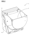
figure 1 shows a front and axonometric view of the coin dispenser and coin meter object of the present invention; -
figure 2 shows an axonometric view of the dispenser offigure 1 in which some parts have been removed for better evidencing the others; -
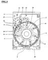
figure 3 shows a front view of the device portion offigure 2 ; -
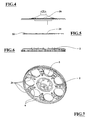
figure 4 shows a side view of one of the elements removed byfigure 2 ; -
figure 5 shows a side view of a prism means offigure 2 ; -
figure 6 shows a side view of a rotating disc offigure 2 ; -
figure 7 shows an axonometric view of the rotating disc offigure 2 ; -
figures 8 and 9 show top and axonometric views of the prism means offigure 2 andfigure 5 . - With reference to
figures 1-9 ,numeral 1 indicates the coin dispenser and coin meter object of the present invention. Thedevice 1 first includes a rotatingdisc 2 associated and coaxial to a second rotatingdisc 26 and cooperating with this latter to transport the coins from acontainer 7 to anoutlet 8. - The first rotating
disc 2 has a parametrictoothed wheel 28 engaged by a motorized pinion for rotating axially said first rotatingdisc 2 jointly to the second rotatingdisc 26. - In an operative condition, the two rotating discs are rotated around their sloping main axis and their lower portions are inside the
coin container 7 and theoutlet 8 is placed closed to their tops. The discs rotate axially in a respective flat andcircular seat 3 carried out in adevice body 4 with the first rotating disc in contact, or almost, with the flat surface of theseat 3. The first star-shaped rotatingdisc 2, with curved arms and inscribed in a perimetrical circle, is equipped with a plurality ofcoin housings 5 separated byshaped arms 6 each arranged to carry a coin from thecontainer 7 to theoutlet 8 and, in cooperation with teeth means 12, for expelling the coin through theoutlet 8. - The
second disc 26 has holes with shaped edges in order to favour the entry of the coins into the same holes. Every hole is opposed to arespective housing 5 of the first rotating disc so that each coin fall from the hole into the corresponding seat. - Moreover, the device includes two sensor means 9 placed in the
seat 3 at a mutual predetermined distance and in data connection with a processor means of the device. - The
device 1 is also equipped with a plurality of activation means 10 each fixed to a respectiveshaped arm 6 and arranged to transit over both sensor means 9, due to rotation of the discs, and to activate each sensors passing thereon. - In addition the
device 1 includes a coin detecting means 11, placed at theoutlet 8. The detecting means 11 is in data connection with the processor means and is activated by the coin exiting from the disc. - The two sensor means 9 and the detector means 11 are optical and their activation occurs when their optical circuit is closed or open.
- Each sensor means 9 includes a respective light emitter means 20, for example a LED (Light Emitter Diode), and a respective and spaced light sensitive means 21, for example a photoresistor or a phototransistor with control circuit.
- The light emitter means 20 and the light sensitive means 21 emit and receive the light in respective operative directions and such means 20, 21 are fixed with respect to the plane of the
seat 3 so that each operative direction are almost perpendicular to the said plane. - The light emitter means 20 and the light detector means 21 are placed under the active end of the activation means 10 when it transits on the sensor means 9 having each light emitter means 20 and light
sensitive means 21. - The activation means 10 is made of transparent material for the light emitted by the light emitter means 20 and is shaped elongated with prisms at its active ends for refracting the light of the emitter means 20 towards the light
sensitive means 21 when this activation means 10 pass on the sensor means 9. - The light
sensitive means 21 sends a signal to the processor means when it receives the light of the respective light emitter means 20 due to the transit of one of the activation means 10 or when the respectiveshaped arm 6 passes on such sensor means 9. In this way the two sensor means 9 send the respective signals at the transit instants of each shaped arm. - The detector means 11 includes a
respective light source 22 and respective and spaced light receiver means 23 having the respective almost parallel operative directions and orthogonal to theoutlet 8. - The light source means 22 and
light receiver 23 are placed under, and spaced by, prismatic respective ends of a light transmitting means made of a material that is transparent to the light made by the light source means 22 to refract the light towards the known light receiver means 23 when none coin engages theoutlet 8 and therefore when there is no obstructions to the light flow between one of the light source means 22 andlight receiver 23 and the light transmitting means. - When a coin reaches the
outlet 8 between the light source means 22 or the light receiver means 23 and one of the end of the light transmission means, this coin intercepts the light and said light receiver means 23 sends a signal to the processor means signalling the instant of the passage. - The
device 1 includes a connecting means 24 reproducing the star shape of the first rotatingdisc 2. The end of each arm of the connectingmeans 24 has a respective activation means 10. Theconnecting means 24 is fixed and interposed between the rotating discs, first 2 and second 26, with each of the activation means 10 faced to a respectiveshaped arm 6. - The connection means 24 is fixed to the face of the first rotating
disc 2 opposite to theseat 3 and eachshaped arm 6 has twoholes 25 for the passage of the light to the ends of the corresponding activation means 10. - In addition the device includes an
optical coin detector 27 placed at the external end of theoutlet 8 and fit to supply a reliable counting of the coins delivered by the device. - In operation condition, the coin detecting means 11 sends a signal to the process means when it detects a coin, each sensor means 9 sends a respective signal to the elaboration means when it detects an activation means 10 of the
shaped arm 6 of this coin or an adjacent predeterminedshaped arm 6, the process means counts the time elapsed between the signals supplied by thecoin detecting means 11 and one of the sensor means 9 and the time elapsed between the signals supplied by the two sensor means 9 to calculate the diameter of the respective coin on the base of a special algorithm memorised in the same process means. - An advantage of the present invention is to supply a coin dispenser and coin meter that is either simple and cheap.
- Other advantage is to supply a precise device without excessive measuring uncertainties.
- A further advantage is to supply a device of reliable operation and of easy and fast maintenance.
Claims (9)
- Distributing and metering device for coins comprising at least a first rotating disc (2) axially rotated on a respective seat (3) carried out in a device body (4), said first rotating disc (2) is provided of a plurality of coin housings (5) separated by shaped arms (6) each fit for conveying a coin from a container (7) to an outlet (8) and, in cooperation with teeth means (12) of the seat (3), for expelling the coin through the outlet (8); said device being characterized in that it comprises at least:- two sensor means (9) placed on the seat (3) at a predetermined mutual distance and data linked to a processor means of the device;- a plurality of activation means (10) each fixed to a respective shaped arm (6) and fit to pass on the two sensor means (9), due to rotation, and to activate said sensors passing on them;- a coin detector means (11), placed on the outlet (8), data linked to the processor means and activated by the exiting coin;in an operating condition, the coin detector means (11) send a signal to the processor means when it detects a coin, each sensor means (9) sends a respective signal to the processor means when it detects an activation means (10) of the shaped arm (6) of said coin or of a predetermined adjacent shaped arm (6), the processor means counts the time between the signals provided by the coin detector means (11) and one of the sensor means (9) and the time between the signals provided by the two sensor means (9) to calculate the diameter of the respective coin.
- Device according to claim 1 characterized in that the two sensor means (9) and the detector means (11) are of optical kind.
- Device according to claim 2 characterized in that each sensor means (9) comprises a respective light emitter means (20) and a respective spaced apart light sensitive means (21) having almost parallel respective operative directions and laid below the active ends of the activation means (10) when it pass on the sensor means (9); said activation means (10) being made of material transparent to said light and being shaped in an elongated manner with prisms at the active ends to deflect the light of the light emitter means (20) to the light sensitive means (21) when said activation means (10) passes on to the sensor means (9); the light sensitive means (21) sending a signal to the processor means when it receives the light of the respective light emitter means (20).
- Device according to claim 2 characterized in that the detector means (11) comprises a respective light source means (22) and a respective spaced apart light receiving means (23) having almost parallel respective operative directions and laid below, and spaced apart to, respective prismatic ends of a light transmitting means made of a material transparent to said light to deflect the light of said light source means (22) to said light receiving means (23) when no coin runs the outlet (8); when a coin reach the outlet (8) between one of said light source means (22) or light receiving means (23) and one of the ends of the light transmitting means, said coin intercepts the light and said light receiving means (23) sends a signal to the processor means.
- Device according to claim 1 characterized in comprising a connecting means (24) reproducing the shape of the first rotating disc (2) and having at each end a respective activation means (10); said connecting means (24) being fixed to the said first rotating disc (2) with each activation means (10) facing a respective shaped arm (6).
- Device according to claim 5 characterized in that the connecting means (24) is fixed to the face of the first rotating disc (2) opposed to the seat (3) and each shaped arm (6) having two holes (25) for the passage of the light up to the ends of the activation means (10).
- Device according to claim 5 characterized in comprising a second rotating disc (26) coaxial with the first one (2) and cooperating with the latter for conveying coins; the connecting means (24) being interposed between the first (2) and the second (26) rotating disc.
- Device according to any of the preceding claims characterized in comprising an optical coin detector (27) placed at the external end of the outlet (8).
- Device according to any of the preceding claims characterized in that the first rotating disc (2) has a perimetrical toothed wheel (28) engaged by a motorized pinion for rotating said first rotating disc (2).
Applications Claiming Priority (1)
| Application Number | Priority Date | Filing Date | Title |
|---|---|---|---|
| IT000448A ITBO20080448A1 (en) | 2008-07-14 | 2008-07-14 | DISPENSER AND COIN METER DEVICE |
Publications (2)
| Publication Number | Publication Date |
|---|---|
| EP2146330A2 true EP2146330A2 (en) | 2010-01-20 |
| EP2146330A3 EP2146330A3 (en) | 2010-11-03 |
Family
ID=40627289
Family Applications (1)
| Application Number | Title | Priority Date | Filing Date |
|---|---|---|---|
| EP09490001A Withdrawn EP2146330A3 (en) | 2008-07-14 | 2009-07-13 | Distributing and measuring device for coins |
Country Status (2)
| Country | Link |
|---|---|
| EP (1) | EP2146330A3 (en) |
| IT (1) | ITBO20080448A1 (en) |
Cited By (8)
| Publication number | Priority date | Publication date | Assignee | Title |
|---|---|---|---|---|
| ITBO20100729A1 (en) * | 2010-12-10 | 2012-06-11 | Alberici S P A | DEVICE FOR DISCRIMINATING AND DELIVERING COINS |
| EP2733682A1 (en) * | 2012-08-21 | 2014-05-21 | Asahi Seiko Co. Ltd. | Coin separating and feeding device |
| EP2966626A1 (en) * | 2014-07-08 | 2016-01-13 | Walter Hanke Mechanische Werkstätten GmbH & Co. KG | Device for separating and dispensing coins |
| WO2016018011A1 (en) * | 2014-07-28 | 2016-02-04 | 은남표 | Coin counting apparatus |
| CN106056748A (en) * | 2016-08-01 | 2016-10-26 | 合肥学院 | Foldable convenient coin sorter |
| EP3104344A1 (en) * | 2015-06-10 | 2016-12-14 | International Currency Technologies Corporation | Coin hopper having an improved coin pushing |
| CN104299309B (en) * | 2013-07-21 | 2017-01-18 | 旭精工株式会社 | Coin dispensing apparatus |
| CN106537467A (en) * | 2014-07-16 | 2017-03-22 | 克雷恩支付解决方案有限公司 | Singulating and validating money items |
Family Cites Families (7)
| Publication number | Priority date | Publication date | Assignee | Title |
|---|---|---|---|---|
| US4407312A (en) * | 1980-05-28 | 1983-10-04 | General Railway Signal Company | Fare collection system and components thereof |
| GB2128795B (en) * | 1982-10-15 | 1986-03-19 | Mach & Systems Limited | Coin sorting apparatus |
| AU5171885A (en) * | 1986-01-25 | 1987-07-02 | Uzihara, H. | Coin delivery |
| US5295899A (en) * | 1992-03-03 | 1994-03-22 | Adams Thomas P | Two disc coin handling apparatus |
| JP3792766B2 (en) * | 1996-01-30 | 2006-07-05 | アルゼ株式会社 | Coin dispensing device for gaming machines |
| WO1999048058A1 (en) * | 1998-03-18 | 1999-09-23 | Cummins-Allison Corp. | Coin processing system for discriminating and counting coins from multiple countries |
| DE102005056191B4 (en) * | 2005-11-21 | 2007-08-16 | Walter Hanke Mechanische Werkstätten GmbH & Co. KG | Device for separating coins |
-
2008
- 2008-07-14 IT IT000448A patent/ITBO20080448A1/en unknown
-
2009
- 2009-07-13 EP EP09490001A patent/EP2146330A3/en not_active Withdrawn
Cited By (11)
| Publication number | Priority date | Publication date | Assignee | Title |
|---|---|---|---|---|
| ITBO20100729A1 (en) * | 2010-12-10 | 2012-06-11 | Alberici S P A | DEVICE FOR DISCRIMINATING AND DELIVERING COINS |
| EP2463829A1 (en) * | 2010-12-10 | 2012-06-13 | Alberici S.p.A. | Device to discriminate and supply coins |
| EP2733682A1 (en) * | 2012-08-21 | 2014-05-21 | Asahi Seiko Co. Ltd. | Coin separating and feeding device |
| CN104299309B (en) * | 2013-07-21 | 2017-01-18 | 旭精工株式会社 | Coin dispensing apparatus |
| EP2966626A1 (en) * | 2014-07-08 | 2016-01-13 | Walter Hanke Mechanische Werkstätten GmbH & Co. KG | Device for separating and dispensing coins |
| CN106537467A (en) * | 2014-07-16 | 2017-03-22 | 克雷恩支付解决方案有限公司 | Singulating and validating money items |
| CN106537467B (en) * | 2014-07-16 | 2019-09-10 | 克雷恩支付创新有限公司 | Separation and verifying payment items |
| WO2016018011A1 (en) * | 2014-07-28 | 2016-02-04 | 은남표 | Coin counting apparatus |
| US9911264B2 (en) | 2014-07-28 | 2018-03-06 | Nam Pyo Eun | Coin counting apparatus |
| EP3104344A1 (en) * | 2015-06-10 | 2016-12-14 | International Currency Technologies Corporation | Coin hopper having an improved coin pushing |
| CN106056748A (en) * | 2016-08-01 | 2016-10-26 | 合肥学院 | Foldable convenient coin sorter |
Also Published As
| Publication number | Publication date |
|---|---|
| ITBO20080448A1 (en) | 2010-01-15 |
| EP2146330A3 (en) | 2010-11-03 |
Similar Documents
| Publication | Publication Date | Title |
|---|---|---|
| EP2146330A2 (en) | Distributing and measuring device for coins | |
| ES2401405T3 (en) | Device to separate and verify coins | |
| US7547248B2 (en) | Disk dispensing apparatus with ejector unit | |
| JP2001286203A (en) | Seeding machine | |
| JP2006527876A (en) | Coin dispensing device | |
| JP2000222611A (en) | Hopper device | |
| CN106575460A (en) | Coin counting apparatus | |
| JP3041343B1 (en) | Dustproof mechanism and high-speed counting device | |
| JP2000135356A (en) | Pachinko ball dispensing device | |
| JP2000325619A (en) | Delivery ball detecting device of pachinko game machine | |
| ES2885061T3 (en) | Device for separating, verifying and transmitting coins | |
| JP5271529B2 (en) | Game machine | |
| ES2773288T3 (en) | Device for separating and distributing coins | |
| JP2006195528A (en) | Hopper device | |
| JPH0249751B2 (en) | ||
| JP6145604B2 (en) | Disc sorting apparatus, disc sorting assembly, and disc processing method using the same | |
| JP4487001B2 (en) | Disk-shaped body feeding device | |
| JP5793608B1 (en) | Medal detection device and gaming machine | |
| JP5286498B2 (en) | False detection prevention device in coin hopper | |
| JP2000210443A (en) | Ball dispensing device for pachinko machine | |
| JP4468263B2 (en) | Hopper device and game machine | |
| EP1647943A3 (en) | Coin and/or token dispenser for automatic distributors or paying devices | |
| JPH02148380A (en) | Money discriminating machine | |
| JP2002113219A (en) | Ball controller | |
| JP2014135055A5 (en) |
Legal Events
| Date | Code | Title | Description |
|---|---|---|---|
| PUAI | Public reference made under article 153(3) epc to a published international application that has entered the european phase |
Free format text: ORIGINAL CODE: 0009012 |
|
| AK | Designated contracting states |
Kind code of ref document: A2 Designated state(s): AT BE BG CH CY CZ DE DK EE ES FI FR GB GR HR HU IE IS IT LI LT LU LV MC MK MT NL NO PL PT RO SE SI SK TR |
|
| AX | Request for extension of the european patent |
Extension state: AL BA RS |
|
| PUAL | Search report despatched |
Free format text: ORIGINAL CODE: 0009013 |
|
| AK | Designated contracting states |
Kind code of ref document: A3 Designated state(s): AT BE BG CH CY CZ DE DK EE ES FI FR GB GR HR HU IE IS IT LI LT LU LV MC MK MT NL NO PL PT RO SE SI SK TR |
|
| AX | Request for extension of the european patent |
Extension state: AL BA RS |
|
| RIC1 | Information provided on ipc code assigned before grant |
Ipc: G07D 9/00 20060101ALI20100927BHEP Ipc: G07D 3/14 20060101AFI20100927BHEP |
|
| STAA | Information on the status of an ep patent application or granted ep patent |
Free format text: STATUS: THE APPLICATION HAS BEEN WITHDRAWN |
|
| 18W | Application withdrawn |
Effective date: 20110504 |
|
| RIN1 | Information on inventor provided before grant (corrected) |
Inventor name: ALBERICI, FABRIZIO |