EP2146303B1 - Lesegerät und Verfahren für auf Rädern stehende RFID-Vorrichtungen - Google Patents
Lesegerät und Verfahren für auf Rädern stehende RFID-Vorrichtungen Download PDFInfo
- Publication number
- EP2146303B1 EP2146303B1 EP09165320.4A EP09165320A EP2146303B1 EP 2146303 B1 EP2146303 B1 EP 2146303B1 EP 09165320 A EP09165320 A EP 09165320A EP 2146303 B1 EP2146303 B1 EP 2146303B1
- Authority
- EP
- European Patent Office
- Prior art keywords
- antenna
- reader system
- transponder
- vehicle
- electric field
- Prior art date
- Legal status (The legal status is an assumption and is not a legal conclusion. Google has not performed a legal analysis and makes no representation as to the accuracy of the status listed.)
- Active
Links
Images


Classifications
-
- G—PHYSICS
- G06—COMPUTING OR CALCULATING; COUNTING
- G06K—GRAPHICAL DATA READING; PRESENTATION OF DATA; RECORD CARRIERS; HANDLING RECORD CARRIERS
- G06K7/00—Methods or arrangements for sensing record carriers, e.g. for reading patterns
- G06K7/10—Methods or arrangements for sensing record carriers, e.g. for reading patterns by electromagnetic radiation, e.g. optical sensing; by corpuscular radiation
- G06K7/10009—Methods or arrangements for sensing record carriers, e.g. for reading patterns by electromagnetic radiation, e.g. optical sensing; by corpuscular radiation sensing by radiation using wavelengths larger than 0.1 mm, e.g. radio-waves or microwaves
- G06K7/10316—Methods or arrangements for sensing record carriers, e.g. for reading patterns by electromagnetic radiation, e.g. optical sensing; by corpuscular radiation sensing by radiation using wavelengths larger than 0.1 mm, e.g. radio-waves or microwaves using at least one antenna particularly designed for interrogating the wireless record carriers
- G06K7/10346—Methods or arrangements for sensing record carriers, e.g. for reading patterns by electromagnetic radiation, e.g. optical sensing; by corpuscular radiation sensing by radiation using wavelengths larger than 0.1 mm, e.g. radio-waves or microwaves using at least one antenna particularly designed for interrogating the wireless record carriers the antenna being of the far field type, e.g. HF types or dipoles
-
- B—PERFORMING OPERATIONS; TRANSPORTING
- B60—VEHICLES IN GENERAL
- B60C—VEHICLE TYRES; TYRE INFLATION; TYRE CHANGING; CONNECTING VALVES TO INFLATABLE ELASTIC BODIES IN GENERAL; DEVICES OR ARRANGEMENTS RELATED TO TYRES
- B60C23/00—Devices for measuring, signalling, controlling, or distributing tyre pressure or temperature, specially adapted for mounting on vehicles; Arrangement of tyre inflating devices on vehicles, e.g. of pumps or of tanks; Tyre cooling arrangements
- B60C23/005—Devices specially adapted for special wheel arrangements
- B60C23/007—Devices specially adapted for special wheel arrangements having multiple wheels arranged side by side
-
- B—PERFORMING OPERATIONS; TRANSPORTING
- B60—VEHICLES IN GENERAL
- B60C—VEHICLE TYRES; TYRE INFLATION; TYRE CHANGING; CONNECTING VALVES TO INFLATABLE ELASTIC BODIES IN GENERAL; DEVICES OR ARRANGEMENTS RELATED TO TYRES
- B60C23/00—Devices for measuring, signalling, controlling, or distributing tyre pressure or temperature, specially adapted for mounting on vehicles; Arrangement of tyre inflating devices on vehicles, e.g. of pumps or of tanks; Tyre cooling arrangements
- B60C23/005—Devices specially adapted for special wheel arrangements
- B60C23/009—Devices specially adapted for special wheel arrangements having wheels on a trailer
-
- B—PERFORMING OPERATIONS; TRANSPORTING
- B60—VEHICLES IN GENERAL
- B60C—VEHICLE TYRES; TYRE INFLATION; TYRE CHANGING; CONNECTING VALVES TO INFLATABLE ELASTIC BODIES IN GENERAL; DEVICES OR ARRANGEMENTS RELATED TO TYRES
- B60C23/00—Devices for measuring, signalling, controlling, or distributing tyre pressure or temperature, specially adapted for mounting on vehicles; Arrangement of tyre inflating devices on vehicles, e.g. of pumps or of tanks; Tyre cooling arrangements
- B60C23/02—Signalling devices actuated by tyre pressure
- B60C23/04—Signalling devices actuated by tyre pressure mounted on the wheel or tyre
- B60C23/0408—Signalling devices actuated by tyre pressure mounted on the wheel or tyre transmitting the signals by non-mechanical means from the wheel or tyre to a vehicle body mounted receiver
- B60C23/0479—Communicating with external units being not part of the vehicle, e.g. tools for diagnostic, mobile phones, electronic keys or service stations
-
- G—PHYSICS
- G06—COMPUTING OR CALCULATING; COUNTING
- G06K—GRAPHICAL DATA READING; PRESENTATION OF DATA; RECORD CARRIERS; HANDLING RECORD CARRIERS
- G06K7/00—Methods or arrangements for sensing record carriers, e.g. for reading patterns
- G06K7/10—Methods or arrangements for sensing record carriers, e.g. for reading patterns by electromagnetic radiation, e.g. optical sensing; by corpuscular radiation
- G06K7/10009—Methods or arrangements for sensing record carriers, e.g. for reading patterns by electromagnetic radiation, e.g. optical sensing; by corpuscular radiation sensing by radiation using wavelengths larger than 0.1 mm, e.g. radio-waves or microwaves
- G06K7/10316—Methods or arrangements for sensing record carriers, e.g. for reading patterns by electromagnetic radiation, e.g. optical sensing; by corpuscular radiation sensing by radiation using wavelengths larger than 0.1 mm, e.g. radio-waves or microwaves using at least one antenna particularly designed for interrogating the wireless record carriers
Definitions
- the invention relates generally to a reader for a radio frequency identification transponder and, more specifically, to a transponder reader for wheel-based RFID devices.
- trailers It is common within the commercial trucking industry for trailers to be either leased by a trailer leasing entity to a trucking company pulling the trailers, or owned directly by the trucking company. In either case, it is important that the tires on each trailer be effectively and efficiently identified and monitored in order to minimize operational costs associated with their use. In addition, it is desirable to identify and monitor the tires on commercial transport vehicles in a cost effective and timely manner in order to maintain control over the identity of the actual tires in use.
- WO-A- 2005/036694 describes a reader system for a wheel-based transponder device in accordance with the preamble of claim 1. Similar devices are also known from WO-A- 2005/072993 and US-A- 4,067,235 .
- the invention relates to a reader system according to claim 1.
- a reader system for a wheel-based, electric field- actuated RFID tag or transponder device including: a support pad for operatively supporting and positioning a vehicle in at least one read location on an upper pad surface; one or more antenna device(s) on the support pad located to operatively align with a wheel-based transponder device of the vehicle with the vehicle positioned on the pad in the read location; one or more transmitter device(s) and receiver device(s) coupled to the antenna device(s) for generating an upwardly directed electric field(s) to actuate the transponder device and receive a responsive signal back from the transponder device.
- the upwardly directed electric field(s) operatively couple with the RFID tag or transponder device as the vehicle drives over the antenna device.
- the antenna device may be configured as one or more dipole antenna(s) either coupled to a common transmitter and receiver device or to respective multiple transmitter and receiver devices.
- the dipole antenna(s) may be partially or entirely embedded within the support pad and may include a reflective member positioned below to direct electric field energy upward from the dipole antenna(s).
- the antenna device may be configured as a generally in-line array of antennae coupled to one or multiple electric field generators, the array aligning with the wheel-based transponder device(s) of the vehicle to operatively direct a plurality of generally in-line electric fields upward toward the wheel unit RFID tag(s) as the vehicle moves over the in-line array.
- the RFID tags or transponder device(s) may be rim or tire mounted to rotate with the wheel unit.
- the in-line array of antennae have a spacing operative to proximally couple with the RFID tags as the wheel unit(s) roll across the pad.
- one or more secondary above-ground antenna device(s) are employed. Each is coupled to an electric field generating transmitter device and located to operatively simultaneously subject the vehicle wheel-mounted transponder device to a secondary electric field with the vehicle in a read location on the pad.
- the antenna device of the reader system may be configured to include: a base layer; a conductive antenna member positioned on the base layer; and a cover layer over the antenna member.
- the antenna member may be configured to include conductive top and bottom plates and a dielectric material layer situated between the top and bottom plates, and, according to an aspect of the invention, the cover layer and the base layer may be composed of respective materials having a respective relative static permittivity less than the relative static permittivity of the dielectric material layer.
- the electric field from the antenna member is thereby configured to extend upward toward the wheel-based transponder.
- FIG. 11 is a side elevation of an alternative embodiment of an antenna device utilizing a dipole and reflective screen.
- a drive-over reader system 100 for a vehicle having one or more wheel mounted transponder devices 102 is shown.
- transponder device is used in its broad connotation and includes devices such as RFID tags and other devices for data storage and transmission.
- the reader system 100 is located within a read station 100 through which the vehicle is preferably, although not necessarily, is driven during a tag-reading operation.
- the vehicle transponder device(s) 102 may be mounted to a wheel unit 110 in a number of locations, such as those identified in FIGS. 1 and 4 as locations A, B, C.
- the wheel unit 110 includes a tire of conventional construction having a pair of beads 112, a tire carcass 114 extending between the beads 112, a tire crown region 120, and a tire inner liner 116.
- the tire is mounted to a wheel rim 118 in conventional fashion.
- One or more wheel units 110 of a vehicle may be provided with one or more transponder devices 102.
- a transponder device in a respective wheel unit 110 may be utilized such as at locations A, B, and C. In addition, other mounting locations may be utilized within the wheel unit 110 to suit the needs and system requirements of the user without departing from the invention.
- Location A mounts the transponder device to center surface of the wheel rim 118 as shown.
- Alternative location B locates the transponder against a sidewall portion of the inner liner 116 of the tire while location C positions the transponder against a crown portion of the inner liner 116.
- location C positions the transponder against a crown portion of the inner liner 116.
- a transponder device may be positioned at all three locations A, B, and C if desired.
- the transponder device is of a type common within the industry combining data storage and transmission capability initiated by receipt of RF signal. Upon activation, the transponder transmits an RF data stream to a remote RF receiver.
- the stored data may include pertinent information that a user would find beneficial to monitor in the operation of a vehicle or a commercial fleet, such as an identification of the vehicle, the tire, the wheel unit, and/or the cargo conveyed by the vehicle and its destination.
- the RF transponder may be read-only or may include read-write capability.
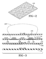
- the antenna device(s) 122 are of layered configuration preferably ranging in thickness from 0.5 to 1.0 inches (1.27 cm to 2.54 cm).
- Each device 122 is structured having a top layer 124 formed of a material providing adequate antenna protection such as a thermoplastic material.
- a loop antenna assembly 126 Positioned below the top layer 124 is a loop antenna assembly 126.
- the loop antenna assembly 126 includes a conductive top plate 127 of relatively smaller width; a dielectric layer 128 positioned beneath the top plate 127; and a conductive plate 130 of wider dimension.
- the antenna assembly 126 is constructed functionally as a capacitor for creating an upwardly directed electro-magnetic field 142.
- mastic layer 134 formed from mastic material suitable for filling in the low spots of the pad on which the assembly 122 is mounted.
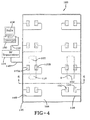
- An array of the antenna devices 122 may be situated within the station 100 in various configurations such as the representative configuration of FIG. 4 .
- the antenna array contains multiple antenna devices 122 and connections therefore on a read station pad 144 in a predetermined spacing.
- the predetermined spacing operatively aligns an electromagnetic field from each antenna device 122 with a respective wheel unit transponder 102 when the wheel unit is positioned over or driven over the transponder.
- One antenna device 122 may be paired with each wheel unit transponder 102 or two or more antenna devices 122-A and 122-B may be positioned to align along the outer edges of a wheel unit 110 to operationally activate a respective antenna device 122 and receive identification data back from the device 122 as shown in FIG. 4 .
- the field generated from a single antenna device or multiple antenna devices such as 122-A, 122-B operatively activate the wheel unit transponder 102 to initiate data transmission.
- Data from the wheel unit transponder(s) 102 are received by the antenna device(s) and relayed by connections 148 to an RF transceiver 154 connected at 252 to a data processing computer 150.
- a display 156 of information to a user is thereby facilitated.
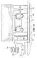
- the read station 100 may be utilized in a commercial trucking operation to monitor and identify a tractor 162 and a trailer 160 as shown in FIGS. 6 and 7 .
- the antenna device(s) 122 are mounted to the pad 144 in a flat orientation. Each device may be secured within a recess within the pad 144 or secured by adhesive or other appropriate means to an upper surface of the pad.
- the relatively low profile of the antenna device 122 minimizes clearance issues with the mud flaps of the tractor and/or trailer as the tractor trailer tandem moves across the pad 144.
- mounting the device(s) 122 to the pad protects the antenna devices 122 from potential damage from contact with outside objects located on or adjacent to the pad 144.
- a drive over reading of the transponders 102 may be facilitated by location of the antenna device(s) below the tractor trailer tandem, whereby reducing the time required in reading the stored data within each transponder 102. Efficiency of operation is thereby enhanced.
- each antenna device 122 may be positioned directly beneath respective tires as shown to generate respective fields operationally coupling with the transponder 102 of each wheel unit as the vehicle moves across the pad.
- the mastic layer 134 at the bottom of each antenna device 122 operates to fill in low spots on the pad 144 and maintain the device 122 at a level attitude.
- the sandwich configuration of the device 122 as described able protects the antenna and provides support.
- the cover layer 124 may be formed of a durable plastic material having a thinner sectional thickness than the bottom base layer 132.
- the cover layer 124 and base layer 132 are preferably formed from a low dielectric loss (transparent) material.
- the field 142 created by the device(s) 122 is established above the antenna device(s) 122 to couple with a respective transponder device 102 as the wheel unit rolls through the electric field.
- the transponder 102 of each wheel unit 110 moves with its wheel unit toward and away from the pad.
- the transponder 102 of each wheel unit 110 By exposing the transponder 102 of each wheel unit 110 to multiple fields from an array of devices 122 as the transponder 102 rotates across the pad with the wheel unit, the probability of achieving a close proximal coupling of the transponder 102 with an electric field is enhanced.
- the efficacy of transponder to field coupling ensures an accurate and expeditious activation of each transponder 102 and reading of data transmitted therefrom.
- FIG. 5 shows an alternative array in which a repeating grouping of three antenna devices 122A-C is positioned across the pad 144.
- the antenna devices 122 are connected by electrical line 146 to an RF transceiver 154.
- the transponder 102 in each wheel unit 110 is activated by the electric field generated by the RF transceiver 154 transmitted through the antenna devices.
- Each of the wheel unit transponders responds with a transmission of data back through the antenna devices to the RF transceiver 154.
- the triangular grouping of antenna devices 122A-C is positioned to create a field that may couple with a transponder 102 in a tandem pair of wheel units 110.
- the antenna devices 122A and 122C align with an outer edge of a respective wheel unit 110A and 110B.
- the antenna device 122B is positioned to align with inward edges of the tandem wheel unit pair with the vehicle in a read position on the pad 144.
- a second grouping of three antenna devices 122D-F align with the tandem wheel units 110A, 110B and as a backup to ensure a positive data download as the wheel units 110A, 110B roll across the pad 144.
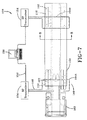
- FIG. 7 and FIG. 8 an alternative system is shown in schematic in which the activation field for forward and rearward transponders 102 of wheel units 110 are generated by forward and rearward loop antennae 164A, B.
- the loop antennae 164A, B are positioned at forward and rearward read locations on the pad 144 and are positioned to generate a respective electro-magnetic field that couples with the four vehicle wheel units.
- the field empowers the transponders 102 in each of the coupled wheel units 110 to transmit data back through connection 152 to RF transceiver 154 and to a data processing computer 156.
- an electric field for the purpose of powering wheel unit transponders may be effected by the use of antennae of various configurations in addition to those described above.
- an array of dipole antennae of the type illustrated in FIG. 11 may be wired into the pad 144 in locations similar to those described above including the layered antenna as in FIGS. 2 and 3 .
- the dipole antennas 166 may be arranged in pairs or used in a line formation to generate the field tuned to empower transponder devices in the wheel units 110.
- the dipoles 166 may be embedded a distance into the pad 144 sufficient to protect the dipoles from damage during use.
- the dipoles 166 may be positioned to read tags on middle sides of dual tires or all tags.
- the relative static permittivity ⁇ r is 5-10.
- dipoles 166 may be embedded in linear formation or triangulated as described. As the vehicle proceeds across the pad 144 and over the embedded dipoles, the tags 100 in the wheel units will couple with one or more dipole fields at a time. Additionally, a reflective screen 168 may be positioned beneath the dipoles 166 within the concrete pad 144 to direct energy from the dipole upward to optimize electrostatic field strength at the wheel unit tag.
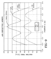
- FIG. 10 depicts a graph of the E field at tag level, with a one volt drive.
- the graph plots electric field intensity at the tag level in a one dipole and a two dipole system.
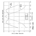
- FIG. 9 is a graph at the tag level showing the effect of adding a reflective screen beneath one dipole and two dipole systems.
- the E field at the tag level is measured utilizing a 1 Watt drive. As shown, the addition of a screen below the dipole(s) beneficially intensifies the E-field at the tag level in both the single and double dipole systems.
- the subject RFID reader reads the RFID tags 102 in a wheel unit 110 as a vehicle drives over a selected location on the pad 144.
- the pad 144 may be located in sundry locations where an identification of the wheel/tire, vehicle, and/or cargo is beneficial to the user.
- the read system may be used for logistics and fleet maintenance of commercial vehicles and can automatically log tires used in lease and maintenance contract locations.
- the antenna devices 122 in the form shown in FIG. 3 or in other antenna configurations such as, but not limited to, the dipole antenna of FIG. 11 , may be buried in the concrete or other material composing the pad 144.
- In line arrays or antenna devices 122 or other configurations may be disposed in a preferred orientation across the pad 144 to ensure that a positive reading of the RFID tag 102 by the time the vehicle departs from the pad 144.
- the embedding of antenna devices within the pad 144 avoids contact with moving obstructions such as the vehicle or mudflaps of the vehicle.
- positioning of the antenna devices 122 within the pad 144 allows suitable location of the devices to read tags of both tires in a dual tire system.
- the antenna device 122 of FIG. 3 utilizes spacers 136, 138, and 140 to structurally reinforce the layered configuration of the device from damage from the vehicle tire rolling over the device.
- the spacers 136, 138, 140 and the cover layer 124 and bottom layer 132 may be composed of a material such as a plastic having a static permittivity less than the dielectric layer 128 of the antenna device so as to concentrate energy out of the device 122.
- Addition of a reflective screen may further be utilized to concentrate the static electric field toward the RFID transponder in the wheel unit in a single or double dipole antenna system as explained previously.
- multiple antenna devices may be configured in an in-line array and connected to one or multiple electric field generators.
- the array aligns with the wheel-based RFID tags of the vehicle and operatively couples a plurality of in-line electric fields with the RFID tag(s) as the vehicle moves over and departs from the pad.
- the RFID tags may be rim or tire mounted to rotate with the wheel unit.
- the in-line array of antennae have a spacing operative to proximally and sequentially couple with the RFID tags as the wheel unit(s) roll across the pad.
- One or more secondary above-ground antenna device(s) are employed in conjunction with the drive-over embedded antennae, each coupled to an electric field generating transmitter device and located to operatively subject the vehicle wheel-mounted RFID tags to a secondary electric field as the vehicle moves across the pad.
Landscapes
- Engineering & Computer Science (AREA)
- Health & Medical Sciences (AREA)
- Toxicology (AREA)
- Physics & Mathematics (AREA)
- Mechanical Engineering (AREA)
- General Health & Medical Sciences (AREA)
- Electromagnetism (AREA)
- Artificial Intelligence (AREA)
- Computer Vision & Pattern Recognition (AREA)
- General Physics & Mathematics (AREA)
- Theoretical Computer Science (AREA)
- Computer Networks & Wireless Communication (AREA)
- Arrangements For Transmission Of Measured Signals (AREA)
- Support Of Aerials (AREA)
Claims (15)
- Lesegerätsystem für eine radbasierte, durch ein elektrisches Feld betätigte Transpondervorrichtung (102) des Typs mit einem Sender zum Übertragen von Daten von einem Fahrzeug zu einem externen Empfänger, wobei das Lesegerätsystem (100) umfasst:eine Stützunterlage zum wirksamen Unterstützen und Positionieren eines Fahrzeugs an mindestens einem Ablesestandort auf einer oberen Unterlagenfläche;mindestens eine Antennenvorrichtung (122) an der Stützunterlage, die so angeordnet ist, dass sie wirksam zu einer am Fahrzeugrad montierten Transpondervorrichtung ausgerichtet ist, wenn sich das Fahrzeug auf der Stützunterlage an dem mindestens einen Ablesestandort befindet;mindestens eine an die Antennenvorrichtung (122) gekoppelte Sendervorrichtung und Empfängervorrichtung zum Erzeugen eines aufwärtsgerichteten elektrischen Feldes (142) zum Betätigen der Transpondervorrichtung und zum wiederum Empfangen eines reagierenden Signals von der Transpondervorrichtung;dadurch gekennzeichnet, dass das Lesegerätsystem (100) weiter mindestens eine sekundäre oberirdische Antennenvorrichtung umfasst, die mit einer ein elektrisches Feld erzeugenden Sendervorrichtung gekoppelt und so angeordnet ist, dass sie die am Fahrzeugrad montierte Transpondervorrichtung wirksam einem sekundären elektrischen Feld aussetzt, wobei sich das Fahrzeug an dem einen Ablesestandort befindet, wobei die eine Antennenvorrichtung und die sekundäre oberirdische Antennenvorrichtung proximal angeordnet sind, um die am Fahrzeugrad montierte Transpondervorrichtung gleichzeitig jeweiligen elektrischen Feldern auszusetzen, wobei sich das Fahrzeug an dem einen Ablesestandort befindet.
- Lesegerätsystem nach Anspruch 1, wobei das aufwärtsgerichtete elektrische Feld (142) wirksam an der Transpondervorrichtung (102) angreift, wenn die Transpondervorrichtung über der einen Antennenvorrichtung (122) passiert.
- Lesegerätsystem nach Anspruch 1 oder 2, wobei die Stützunterlage sich zwischen einem Fahrzeugeingang und einem Fahrzeugausgangstor erstreckt, um eine überfahrbare, mittels eines elektrischen Feldes wirkende Betätigung der Transpondervorrichtung wirksam zu erleichtern.
- Lesegerätsystem nach einem der vorgenannten Ansprüche, wobei die Antennenvorrichtung (122) mindestens eine an die Sender- und Empfängervorrichtung gekoppelte Dipolantenne umfasst.
- Lesegerätsystem nach Anspruch 4, wobei die mindestens eine Dipolantenne mindestens teilweise in die Stützunterlage eingebettet ist.
- Lesegerätsystem nach einem der vorgenannten Ansprüche, wobei die Antennenvorrichtung eine Vielzahl proximal positionierter und benachbarter Antennen umfasst, die an die Sender- und Empfängervorrichtung gekoppelt sind, um die Transpondervorrichtung jeweiligen elektrischen Feldern auszusetzen.
- Lesegerätsystem nach einem der vorgenannten Ansprüche, wobei die Antennenvorrichtung mindestens eine lineare oder generell lineare Anordnung von Antennen umfasst, die an Mittel zur Erzeugung eines elektrischen Feldes gekoppelt und auf der Stützunterlage positioniert sind, wobei die Anordnung zu der am Fahrzeugrad montierten Transpondervorrichtung ausgerichtet ist, um eine Vielzahl generell linear angeordneter elektrischer Felder wirksam aufwärts zu der Transpondervorrichtung zu lenken, wenn sich das Fahrzeug über die lineare Anordnung von Antennen bewegt.
- Lesegerätsystem nach Anspruch 7, wobei die Transpondervorrichtung an einer Fahrzeugrad-Einheit (110) montiert ist und damit rotiert, und wobei die lineare Anordnung von Antennen eine Beabstandung aufweist, die wirksam ist, um die Transpondervorrichtung einer Abfolge elektrischen Feldes auszusetzen, wenn sich die Transpondervorrichtung über die lineare Anordnung von Antennen bewegt.
- Lesegerätsystem nach Anspruch 1, wobei die mindestens eine Antennenvorrichtung eine Basisschicht (132), ein auf der Basisschicht (132) positioniertes leitfähiges Antennenelement (130) und über dem Antennenelement eine Abdeckschicht (124) umfasst.
- Lesegerätsystem nach Anspruch 9, wobei die mindestens eine Antennenvorrichtung weiter ein zwischen der Basisschicht (132) und der Abdeckschicht (124) befindliches Abstandshalterelement (136, 138, 140) umfasst.
- Lesegerätsystem nach Anspruch 9, wobei das Antennenelement eine leitfähige obere und untere Platte (127, 130) und eine zwischen der oberen und der unteren Platte angeordnete dielektrische Materialschicht (128) umfasst.
- Lesegerätsystem nach Anspruch 9 oder 11, wobei die Abdeckschicht und die Basisschicht aus jeweiligen Materialien zusammengesetzt sind, die eine jeweilige statische Dielektrizitätskonstante aufweisen, die kleiner als die relative statische Dielektrizitätskonstante der dielektrischen Materialschicht ist, und/oder wobei die Abdeckschicht und die Basisschicht mindestens teilweise aus thermoplastischem Material zusammengesetzt sind.
- Lesegerätsystem nach Anspruch 9, 11 oder 12, weiter eine Mastixschicht (134) unter der Basisschicht (132) zum Befestigen der Antennenvorrichtung an der oberen Unterlagenfläche der Stützunterlage umfassend.
- Lesegerätsystem nach einem der vorgenannten Ansprüche, wobei die Antennenvorrichtung mindestens eine in der Stützunterlage eingebettete und davon bedeckte Dipolantenne umfasst.
- Lesegerätsystem nach Anspruch 14, wobei sich ein reflektierendes Element unter der einen Dipolantenne befindet, um wirksam Energie von der einen Dipolantenne nach oben zu lenken.
Applications Claiming Priority (1)
| Application Number | Priority Date | Filing Date | Title |
|---|---|---|---|
| US12/172,316 US9000923B2 (en) | 2008-07-14 | 2008-07-14 | Reader and method for wheel-based RFID devices |
Publications (2)
| Publication Number | Publication Date |
|---|---|
| EP2146303A1 EP2146303A1 (de) | 2010-01-20 |
| EP2146303B1 true EP2146303B1 (de) | 2014-04-16 |
Family
ID=41128184
Family Applications (1)
| Application Number | Title | Priority Date | Filing Date |
|---|---|---|---|
| EP09165320.4A Active EP2146303B1 (de) | 2008-07-14 | 2009-07-13 | Lesegerät und Verfahren für auf Rädern stehende RFID-Vorrichtungen |
Country Status (3)
| Country | Link |
|---|---|
| US (1) | US9000923B2 (de) |
| EP (1) | EP2146303B1 (de) |
| BR (1) | BRPI0902341B1 (de) |
Families Citing this family (10)
| Publication number | Priority date | Publication date | Assignee | Title |
|---|---|---|---|---|
| EP1863657B1 (de) * | 2005-03-31 | 2012-05-09 | PIRELLI TYRE S.p.A. | Eine vorrichtung zur erfassung mindestens eines charakteristischen parameters des reifens selbst umfassender reifen und herstellungsverfahren dafür |
| TW200935315A (en) * | 2008-02-01 | 2009-08-16 | Taiwan Name Plate Co Ltd | An ordering catalog with electronic bookmarks |
| DE102010026872A1 (de) * | 2010-07-12 | 2012-01-12 | Knorr-Bremse Systeme für Nutzfahrzeuge GmbH | Vorrichtung zur Zuordnung von Positionen von Reifensensoren an einem Fahrzeug |
| DE102011083427A1 (de) * | 2011-09-26 | 2013-03-28 | Siemens Aktiengesellschaft | System zur Positionsbestimmung von zueinander beweglichen Objekten |
| KR101557245B1 (ko) * | 2014-12-03 | 2015-10-21 | 성균관대학교산학협력단 | 타이어 코드지용 섬유를 이용한 정전기 에너지 발생장치 |
| GB2545693B (en) * | 2015-12-22 | 2020-05-20 | Schrader Electronics Ltd | Advanced tire monitoring system |
| US11198328B2 (en) | 2016-04-19 | 2021-12-14 | Bridgestone Americas Tire Operations, Llc | Tire with electronic device having a reinforcing cord antenna |
| US11421982B2 (en) | 2020-05-28 | 2022-08-23 | The Goodyear Tire & Rubber Company | System and method for estimating tire tread depth |
| US11413912B2 (en) | 2020-12-15 | 2022-08-16 | The Goodyear Tire & Rubber Company | System and method for temperature compensation of drive over reader pressure measurement |
| US20220185037A1 (en) * | 2020-12-15 | 2022-06-16 | The Goodyear Tire & Rubber Company | System and method for evaluation of tire pressure |
Citations (1)
| Publication number | Priority date | Publication date | Assignee | Title |
|---|---|---|---|---|
| US5821525A (en) * | 1994-08-03 | 1998-10-13 | Mitsubishi Denki Kabushiki Kaisha | Reader/writer for use with non-contact IC card and reader/writer system |
Family Cites Families (4)
| Publication number | Priority date | Publication date | Assignee | Title |
|---|---|---|---|---|
| US4067235A (en) | 1974-11-27 | 1978-01-10 | Consolidated Freightways, Inc. | Method and apparatus for measuring air pressure in pneumatic tires |
| US7161476B2 (en) * | 2000-07-26 | 2007-01-09 | Bridgestone Firestone North American Tire, Llc | Electronic tire management system |
| US7196637B2 (en) * | 2003-10-02 | 2007-03-27 | Emag Technologies, Inc. | Antenna system embedded in a support structure for interrogating a tire sensor transponder |
| GB0402240D0 (en) * | 2004-02-02 | 2004-03-03 | Transense Technologies Plc | Remote interrogation of a vehicle wheel |
-
2008
- 2008-07-14 US US12/172,316 patent/US9000923B2/en active Active
-
2009
- 2009-07-02 BR BRPI0902341-0A patent/BRPI0902341B1/pt not_active IP Right Cessation
- 2009-07-13 EP EP09165320.4A patent/EP2146303B1/de active Active
Patent Citations (1)
| Publication number | Priority date | Publication date | Assignee | Title |
|---|---|---|---|---|
| US5821525A (en) * | 1994-08-03 | 1998-10-13 | Mitsubishi Denki Kabushiki Kaisha | Reader/writer for use with non-contact IC card and reader/writer system |
Also Published As
| Publication number | Publication date |
|---|---|
| US20100007465A1 (en) | 2010-01-14 |
| US9000923B2 (en) | 2015-04-07 |
| EP2146303A1 (de) | 2010-01-20 |
| BRPI0902341B1 (pt) | 2019-11-05 |
| BRPI0902341A2 (pt) | 2010-04-13 |
Similar Documents
| Publication | Publication Date | Title |
|---|---|---|
| EP2146303B1 (de) | Lesegerät und Verfahren für auf Rädern stehende RFID-Vorrichtungen | |
| US7969293B2 (en) | Integrated read station for a wheel-mounted vehicle | |
| US8977422B1 (en) | Accoustic/vibration sensor and tire assembly and method of construction thereof | |
| US20120291936A1 (en) | Embedded transponder and tire assembly and method of construction thereof | |
| US10919348B2 (en) | Tire with RFID locator | |
| US8115610B2 (en) | RFID enabled tire control system and method | |
| EP1720721B1 (de) | Fernabfrage eines fahrzeugsrads | |
| US9679174B2 (en) | System for the dynamic reading of data from transponders | |
| US20140002242A1 (en) | Tire rfid tag reader portal system and method | |
| US20160379020A1 (en) | System for the dynamic reading of data from transponders | |
| EP2829659B1 (de) | Überfahrbarer Ständer und Antennenanordnung | |
| US20210021015A1 (en) | Reader system for tire with an integrated rfid and tpms sensor | |
| US20090195373A1 (en) | Initiator system and method for a tire pressure monitoring system | |
| US9135479B2 (en) | Antenna assembly for a tag reader | |
| US12346762B2 (en) | Tire provided with a temporary identification label | |
| US20260042321A1 (en) | Tire with Treadwear Monitoring | |
| EP4353498A1 (de) | Reifen mit einem temporären identifikationsetikett | |
| EP2339692B1 (de) | Antennenanordnung für einen Etikettenleser und Verfahren zum Lesen von Übertragungsdaten | |
| EP4245576B1 (de) | Luftreifen | |
| CN121492531A (zh) | 具有胎面磨损监视功能的轮胎 |
Legal Events
| Date | Code | Title | Description |
|---|---|---|---|
| PUAI | Public reference made under article 153(3) epc to a published international application that has entered the european phase |
Free format text: ORIGINAL CODE: 0009012 |
|
| AK | Designated contracting states |
Kind code of ref document: A1 Designated state(s): AT BE BG CH CY CZ DE DK EE ES FI FR GB GR HR HU IE IS IT LI LT LU LV MC MK MT NL NO PL PT RO SE SI SK SM TR |
|
| AX | Request for extension of the european patent |
Extension state: AL BA RS |
|
| 17P | Request for examination filed |
Effective date: 20100720 |
|
| 17Q | First examination report despatched |
Effective date: 20100817 |
|
| GRAP | Despatch of communication of intention to grant a patent |
Free format text: ORIGINAL CODE: EPIDOSNIGR1 |
|
| INTG | Intention to grant announced |
Effective date: 20131108 |
|
| GRAS | Grant fee paid |
Free format text: ORIGINAL CODE: EPIDOSNIGR3 |
|
| GRAA | (expected) grant |
Free format text: ORIGINAL CODE: 0009210 |
|
| AK | Designated contracting states |
Kind code of ref document: B1 Designated state(s): AT BE BG CH CY CZ DE DK EE ES FI FR GB GR HR HU IE IS IT LI LT LU LV MC MK MT NL NO PL PT RO SE SI SK SM TR |
|
| REG | Reference to a national code |
Ref country code: GB Ref legal event code: FG4D |
|
| REG | Reference to a national code |
Ref country code: CH Ref legal event code: EP |
|
| REG | Reference to a national code |
Ref country code: AT Ref legal event code: REF Ref document number: 662940 Country of ref document: AT Kind code of ref document: T Effective date: 20140515 |
|
| REG | Reference to a national code |
Ref country code: IE Ref legal event code: FG4D |
|
| REG | Reference to a national code |
Ref country code: DE Ref legal event code: R096 Ref document number: 602009023243 Country of ref document: DE Effective date: 20140528 |
|
| REG | Reference to a national code |
Ref country code: AT Ref legal event code: MK05 Ref document number: 662940 Country of ref document: AT Kind code of ref document: T Effective date: 20140416 |
|
| REG | Reference to a national code |
Ref country code: NL Ref legal event code: VDEP Effective date: 20140416 |
|
| REG | Reference to a national code |
Ref country code: LT Ref legal event code: MG4D |
|
| PG25 | Lapsed in a contracting state [announced via postgrant information from national office to epo] |
Ref country code: IS Free format text: LAPSE BECAUSE OF FAILURE TO SUBMIT A TRANSLATION OF THE DESCRIPTION OR TO PAY THE FEE WITHIN THE PRESCRIBED TIME-LIMIT Effective date: 20140816 Ref country code: NL Free format text: LAPSE BECAUSE OF FAILURE TO SUBMIT A TRANSLATION OF THE DESCRIPTION OR TO PAY THE FEE WITHIN THE PRESCRIBED TIME-LIMIT Effective date: 20140416 Ref country code: BG Free format text: LAPSE BECAUSE OF FAILURE TO SUBMIT A TRANSLATION OF THE DESCRIPTION OR TO PAY THE FEE WITHIN THE PRESCRIBED TIME-LIMIT Effective date: 20140716 Ref country code: CY Free format text: LAPSE BECAUSE OF FAILURE TO SUBMIT A TRANSLATION OF THE DESCRIPTION OR TO PAY THE FEE WITHIN THE PRESCRIBED TIME-LIMIT Effective date: 20140416 Ref country code: FI Free format text: LAPSE BECAUSE OF FAILURE TO SUBMIT A TRANSLATION OF THE DESCRIPTION OR TO PAY THE FEE WITHIN THE PRESCRIBED TIME-LIMIT Effective date: 20140416 Ref country code: NO Free format text: LAPSE BECAUSE OF FAILURE TO SUBMIT A TRANSLATION OF THE DESCRIPTION OR TO PAY THE FEE WITHIN THE PRESCRIBED TIME-LIMIT Effective date: 20140716 Ref country code: GR Free format text: LAPSE BECAUSE OF FAILURE TO SUBMIT A TRANSLATION OF THE DESCRIPTION OR TO PAY THE FEE WITHIN THE PRESCRIBED TIME-LIMIT Effective date: 20140717 Ref country code: LT Free format text: LAPSE BECAUSE OF FAILURE TO SUBMIT A TRANSLATION OF THE DESCRIPTION OR TO PAY THE FEE WITHIN THE PRESCRIBED TIME-LIMIT Effective date: 20140416 |
|
| PG25 | Lapsed in a contracting state [announced via postgrant information from national office to epo] |
Ref country code: LV Free format text: LAPSE BECAUSE OF FAILURE TO SUBMIT A TRANSLATION OF THE DESCRIPTION OR TO PAY THE FEE WITHIN THE PRESCRIBED TIME-LIMIT Effective date: 20140416 Ref country code: PL Free format text: LAPSE BECAUSE OF FAILURE TO SUBMIT A TRANSLATION OF THE DESCRIPTION OR TO PAY THE FEE WITHIN THE PRESCRIBED TIME-LIMIT Effective date: 20140416 Ref country code: HR Free format text: LAPSE BECAUSE OF FAILURE TO SUBMIT A TRANSLATION OF THE DESCRIPTION OR TO PAY THE FEE WITHIN THE PRESCRIBED TIME-LIMIT Effective date: 20140416 Ref country code: SE Free format text: LAPSE BECAUSE OF FAILURE TO SUBMIT A TRANSLATION OF THE DESCRIPTION OR TO PAY THE FEE WITHIN THE PRESCRIBED TIME-LIMIT Effective date: 20140416 Ref country code: AT Free format text: LAPSE BECAUSE OF FAILURE TO SUBMIT A TRANSLATION OF THE DESCRIPTION OR TO PAY THE FEE WITHIN THE PRESCRIBED TIME-LIMIT Effective date: 20140416 Ref country code: ES Free format text: LAPSE BECAUSE OF FAILURE TO SUBMIT A TRANSLATION OF THE DESCRIPTION OR TO PAY THE FEE WITHIN THE PRESCRIBED TIME-LIMIT Effective date: 20140416 |
|
| PG25 | Lapsed in a contracting state [announced via postgrant information from national office to epo] |
Ref country code: PT Free format text: LAPSE BECAUSE OF FAILURE TO SUBMIT A TRANSLATION OF THE DESCRIPTION OR TO PAY THE FEE WITHIN THE PRESCRIBED TIME-LIMIT Effective date: 20140818 |
|
| REG | Reference to a national code |
Ref country code: DE Ref legal event code: R097 Ref document number: 602009023243 Country of ref document: DE |
|
| PG25 | Lapsed in a contracting state [announced via postgrant information from national office to epo] |
Ref country code: CZ Free format text: LAPSE BECAUSE OF FAILURE TO SUBMIT A TRANSLATION OF THE DESCRIPTION OR TO PAY THE FEE WITHIN THE PRESCRIBED TIME-LIMIT Effective date: 20140416 Ref country code: BE Free format text: LAPSE BECAUSE OF FAILURE TO SUBMIT A TRANSLATION OF THE DESCRIPTION OR TO PAY THE FEE WITHIN THE PRESCRIBED TIME-LIMIT Effective date: 20140416 Ref country code: DK Free format text: LAPSE BECAUSE OF FAILURE TO SUBMIT A TRANSLATION OF THE DESCRIPTION OR TO PAY THE FEE WITHIN THE PRESCRIBED TIME-LIMIT Effective date: 20140416 Ref country code: SK Free format text: LAPSE BECAUSE OF FAILURE TO SUBMIT A TRANSLATION OF THE DESCRIPTION OR TO PAY THE FEE WITHIN THE PRESCRIBED TIME-LIMIT Effective date: 20140416 Ref country code: RO Free format text: LAPSE BECAUSE OF FAILURE TO SUBMIT A TRANSLATION OF THE DESCRIPTION OR TO PAY THE FEE WITHIN THE PRESCRIBED TIME-LIMIT Effective date: 20140416 Ref country code: EE Free format text: LAPSE BECAUSE OF FAILURE TO SUBMIT A TRANSLATION OF THE DESCRIPTION OR TO PAY THE FEE WITHIN THE PRESCRIBED TIME-LIMIT Effective date: 20140416 |
|
| PLBE | No opposition filed within time limit |
Free format text: ORIGINAL CODE: 0009261 |
|
| STAA | Information on the status of an ep patent application or granted ep patent |
Free format text: STATUS: NO OPPOSITION FILED WITHIN TIME LIMIT |
|
| PG25 | Lapsed in a contracting state [announced via postgrant information from national office to epo] |
Ref country code: LU Free format text: LAPSE BECAUSE OF FAILURE TO SUBMIT A TRANSLATION OF THE DESCRIPTION OR TO PAY THE FEE WITHIN THE PRESCRIBED TIME-LIMIT Effective date: 20140713 |
|
| REG | Reference to a national code |
Ref country code: CH Ref legal event code: PL |
|
| 26N | No opposition filed |
Effective date: 20150119 |
|
| GBPC | Gb: european patent ceased through non-payment of renewal fee |
Effective date: 20140716 |
|
| REG | Reference to a national code |
Ref country code: IE Ref legal event code: MM4A |
|
| PG25 | Lapsed in a contracting state [announced via postgrant information from national office to epo] |
Ref country code: CH Free format text: LAPSE BECAUSE OF NON-PAYMENT OF DUE FEES Effective date: 20140731 Ref country code: LI Free format text: LAPSE BECAUSE OF NON-PAYMENT OF DUE FEES Effective date: 20140731 |
|
| REG | Reference to a national code |
Ref country code: DE Ref legal event code: R097 Ref document number: 602009023243 Country of ref document: DE Effective date: 20150119 |
|
| PG25 | Lapsed in a contracting state [announced via postgrant information from national office to epo] |
Ref country code: GB Free format text: LAPSE BECAUSE OF NON-PAYMENT OF DUE FEES Effective date: 20140716 |
|
| PG25 | Lapsed in a contracting state [announced via postgrant information from national office to epo] |
Ref country code: SI Free format text: LAPSE BECAUSE OF FAILURE TO SUBMIT A TRANSLATION OF THE DESCRIPTION OR TO PAY THE FEE WITHIN THE PRESCRIBED TIME-LIMIT Effective date: 20140416 |
|
| PG25 | Lapsed in a contracting state [announced via postgrant information from national office to epo] |
Ref country code: IE Free format text: LAPSE BECAUSE OF NON-PAYMENT OF DUE FEES Effective date: 20140713 |
|
| PG25 | Lapsed in a contracting state [announced via postgrant information from national office to epo] |
Ref country code: MC Free format text: LAPSE BECAUSE OF FAILURE TO SUBMIT A TRANSLATION OF THE DESCRIPTION OR TO PAY THE FEE WITHIN THE PRESCRIBED TIME-LIMIT Effective date: 20140416 Ref country code: SM Free format text: LAPSE BECAUSE OF FAILURE TO SUBMIT A TRANSLATION OF THE DESCRIPTION OR TO PAY THE FEE WITHIN THE PRESCRIBED TIME-LIMIT Effective date: 20140416 |
|
| REG | Reference to a national code |
Ref country code: FR Ref legal event code: PLFP Year of fee payment: 8 |
|
| PG25 | Lapsed in a contracting state [announced via postgrant information from national office to epo] |
Ref country code: MT Free format text: LAPSE BECAUSE OF FAILURE TO SUBMIT A TRANSLATION OF THE DESCRIPTION OR TO PAY THE FEE WITHIN THE PRESCRIBED TIME-LIMIT Effective date: 20140416 |
|
| PG25 | Lapsed in a contracting state [announced via postgrant information from national office to epo] |
Ref country code: HU Free format text: LAPSE BECAUSE OF FAILURE TO SUBMIT A TRANSLATION OF THE DESCRIPTION OR TO PAY THE FEE WITHIN THE PRESCRIBED TIME-LIMIT; INVALID AB INITIO Effective date: 20090713 Ref country code: TR Free format text: LAPSE BECAUSE OF FAILURE TO SUBMIT A TRANSLATION OF THE DESCRIPTION OR TO PAY THE FEE WITHIN THE PRESCRIBED TIME-LIMIT Effective date: 20140416 |
|
| REG | Reference to a national code |
Ref country code: FR Ref legal event code: PLFP Year of fee payment: 9 |
|
| REG | Reference to a national code |
Ref country code: FR Ref legal event code: PLFP Year of fee payment: 10 |
|
| PG25 | Lapsed in a contracting state [announced via postgrant information from national office to epo] |
Ref country code: MK Free format text: LAPSE BECAUSE OF FAILURE TO SUBMIT A TRANSLATION OF THE DESCRIPTION OR TO PAY THE FEE WITHIN THE PRESCRIBED TIME-LIMIT Effective date: 20140416 |
|
| PGFP | Annual fee paid to national office [announced via postgrant information from national office to epo] |
Ref country code: IT Payment date: 20210610 Year of fee payment: 13 |
|
| PG25 | Lapsed in a contracting state [announced via postgrant information from national office to epo] |
Ref country code: IT Free format text: LAPSE BECAUSE OF NON-PAYMENT OF DUE FEES Effective date: 20220713 |
|
| PGFP | Annual fee paid to national office [announced via postgrant information from national office to epo] |
Ref country code: FR Payment date: 20250620 Year of fee payment: 17 |
|
| PGFP | Annual fee paid to national office [announced via postgrant information from national office to epo] |
Ref country code: DE Payment date: 20250620 Year of fee payment: 17 |