EP2146144A2 - Combustion burner of a mixture of hydrogen and oxygen - Google Patents
Combustion burner of a mixture of hydrogen and oxygen Download PDFInfo
- Publication number
- EP2146144A2 EP2146144A2 EP09164878A EP09164878A EP2146144A2 EP 2146144 A2 EP2146144 A2 EP 2146144A2 EP 09164878 A EP09164878 A EP 09164878A EP 09164878 A EP09164878 A EP 09164878A EP 2146144 A2 EP2146144 A2 EP 2146144A2
- Authority
- EP
- European Patent Office
- Prior art keywords
- mixture
- oxygen
- combustion
- hydrogen
- flame
- Prior art date
- Legal status (The legal status is an assumption and is not a legal conclusion. Google has not performed a legal analysis and makes no representation as to the accuracy of the status listed.)
- Withdrawn
Links
Images


Classifications
-
- F—MECHANICAL ENGINEERING; LIGHTING; HEATING; WEAPONS; BLASTING
- F23—COMBUSTION APPARATUS; COMBUSTION PROCESSES
- F23D—BURNERS
- F23D14/00—Burners for combustion of a gas, e.g. of a gas stored under pressure as a liquid
- F23D14/02—Premix gas burners, i.e. in which gaseous fuel is mixed with combustion air upstream of the combustion zone
- F23D14/04—Premix gas burners, i.e. in which gaseous fuel is mixed with combustion air upstream of the combustion zone induction type, e.g. Bunsen burner
- F23D14/06—Premix gas burners, i.e. in which gaseous fuel is mixed with combustion air upstream of the combustion zone induction type, e.g. Bunsen burner with radial outlets at the burner head
-
- F—MECHANICAL ENGINEERING; LIGHTING; HEATING; WEAPONS; BLASTING
- F23—COMBUSTION APPARATUS; COMBUSTION PROCESSES
- F23D—BURNERS
- F23D14/00—Burners for combustion of a gas, e.g. of a gas stored under pressure as a liquid
- F23D14/32—Burners for combustion of a gas, e.g. of a gas stored under pressure as a liquid using a mixture of gaseous fuel and pure oxygen or oxygen-enriched air
-
- F—MECHANICAL ENGINEERING; LIGHTING; HEATING; WEAPONS; BLASTING
- F24—HEATING; RANGES; VENTILATING
- F24C—DOMESTIC STOVES OR RANGES ; DETAILS OF DOMESTIC STOVES OR RANGES, OF GENERAL APPLICATION
- F24C3/00—Stoves or ranges for gaseous fuels
- F24C3/08—Arrangement or mounting of burners
Definitions
- the present invention relates to a combustion burner of a mixture of hydrogen and oxygen which can be applied to a gas instrument for heating a container using a burning flame of a mixture of hydrogen and oxygen produced from water.
- the apparatus for generating a harmful mixture of hydrogen and oxygen is directed to generating a mixture of hydrogen and oxygen which are obtained based on an electrolysis and does not produce pollution and are not harmful in such a manner that water with a small amount of electrolyte to an electrolytic cell with positive and negative electrodes.
- the hydrogen and oxygen are produced at a mole ratio of 2:1, the hydrogen produced in a bubble shape at the surface of the negative electrode, the oxygen produced in a bubble shape at the surface of the positive electrode.
- the thusly produced hydrogen and oxygen are mixed in a mixed gas form, which can burn.
- the mixture of hydrogen and oxygen does not produce pollutants, it is very friendly and can be recognized as a new energy source.
- a combustion flame of a mixture of hydrogen and oxygen has a narrow rod shape. As shown in Figure 1 , a combustion flame C of a mixture of hydrogen and oxygen has a high temperature flame core N in its interior, whose temperature reaches 3,000 ⁇ 6,000°C.
- the metal used to make a container for cooking foods melts at about 2,000°C. Since the temperature of the flame core N of a combustion flame C of a mixture of hydrogen and oxygen reaches 3,000 ⁇ 6,000°C, the portion contacting with the flame core N melts. So, it is not proper to use the combustion flame C of a mixture of hydrogen and oxygen when heating a container. Since the flame in the course of combustion has a rod shape, it is impossible to heat wider area, which leads to a limited use of combustion heat.
- a combustion burner of a mixture of hydrogen and oxygen comprising a body part 11 which is airtight connected with a gas line L used for supplying a mixture of hydrogen and oxygen gases while preventing oxygen from being externally inputted and is generally formed in a cylindrical shape; a combustion part 12 whose inclined surface is formed in a rim shape along an upper edge portion of the body part 11; a plurality of flame holes 13 which are formed at regular intervals along an inclined surface of the combustion part; a distribution part 14 which is formed in the interior of the body part 11 and distributes a mixture of hydrogen and oxygen gases inputted through the gas line L toward the flame holes 13; and an ignition medium cap 17 which is installed in an upper side of the body part 11and allows the combustion flame burned through the flame hole 13 to ignite a mixture of gases which is sprayed through other flame holes, wherein the diameter of the flame holes 13 is in a range of 0.2mm-2mm.
- a suspending part 16 is formed in a lower side of the body part 11 and is suspended over the through holes G1 formed in the upper plate of the gas instrument.
- the flame holes 13 are formed at an angle of 5 ⁇ 90° with respect to a center axis.
- an ignition medium cap 17 which is installed in an upper side of the body part 11 in order for the combustion flame burned through a certain flame hole 13 to ignite a mixture of hydrogen and oxygen gases which is sprayed through other flame holes.
- the combustion burner of a mixture of hydrogen and oxygen according to the present invention, it is possible to heat a wider area by preventing a high temperature flame core from being produced in the interior of a combustion flame and by creasing the entire volume of a container used for cooking foods.
- the combustion burner according to the present invention can be applied to a variety of fields since a gas instrument similar with a conventional gas range can be implemented.
- Figure 2 is a perspective view illustrating a gas instrument equipped with a combustion burner of a mixture of hydrogen and oxygen gases according to the present invention
- Figure 3 is a perspective view of a combustion burner of Figure 2
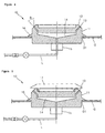
- Figure 4 is a cross sectional view taken along the line IV-IV' of Figure 3
- Figure 5 is a view for describing a state that an ignition medium cap is installed in the body part of Figure 4 .
- the combustion burner of a mixture of hydrogen and oxygen is installed on an upper plate of a gas instrument G on which a container used for cooking foods is placed.
- the combustion burner 10 comprises a body part 11 which is airtight connected with a gas line L used for supplying a mixture of hydrogen and oxygen gases while preventing oxygen from being externally inputted and is generally formed in a cylindrical shape; a combustion part 12 whose inclined surface is formed in a rim shape along an upper edge portion of the body part 11; a plurality of flame holes 13 which are formed at regular intervals along an inclined surface of the combustion part; and a distribution part 14 which is formed in the interior of the body part 11 and distributes a mixture of hydrogen and oxygen gases inputted through the gas line L toward the flame holes 13.
- the body part 11 and the combustion part 12 are integral with each other and are made by processing one selected from the group comprising stainless steel, tungsten, nonferrous metal, and alloy steel.
- a connection part 15 connected with a gas line L for supplying a mixture gas of hydrogen and oxygen is formed in a lower side of a body part 11.
- the gas line L and the connection part 15 have a seal engaged structure for preventing an external oxygen of a combustion burner of the present invention from being inputted. Since oxygen is contained in a mixture of hydrogen and oxygen produced in the course of decomposing water, when an external oxygen is inputted, a stable combustion cannot be obtained.
- a suspending part 16 suspended over a through hole G1 formed in an upper plate of the gas instrument is disposed in a lower side of the body part 11, so it is possible to easily apply the combustion burner 10 of the present invention to a gas instrument.
- Flame homes 13 are formed along an inclined surface of the combustion part at regular intervals.
- the flame holes 13 are formed at an angle range of 5 ⁇ 90° with respect to a center axis.
- the flame holes 13 are formed at an angle of 45° with respect to a center axis.
- the diameter of the flame hole 13 is 0.2mm through 2mm, and in the embodiment of the present invention, it is 1 mm. It is possible to adjust the heat calorie of the combustion flame by increasing or decreasing the number of the flame holes 13.
- the diameters of the flame holes 13 are small and of the units of mm, so the spraying pressure of the mixture of hydrogen and oxygen is low, and it is partially mixed with an external air in the course of combustion. Since the mixture of hydrogen and oxygen sprayed with a lower pressure is partially mixed with air, so flame cores of Figure 1 do not occur.
- the distribution part 14 distributes a mixture of hydrogen and oxygen toward the flame holes 13.
- the distribution part 14 is disposed in the interior of the body part 11 while substantially being sealed from the outside.
- An ignition medium cap 17 is installed on an upper side of the body part 11 foe helping combustion flame from the flame hole 13 to ignite a mixture of gases which are sprayed through the flame holes.
- the ignition medium cap 17 allows the combustion flames burning through the flame holes 13 to spread toward the surrounding, so combustion flames are transferred to other flame holes.
- the ignition medium cap 17 is able to prevent the overflowing foods from blocking the flame holes 13.
- a mixture of hydrogen and oxygen inputted through a gas line L is divided into flame holes 13 and is spread.
- the mixture of hydrogen and oxygen, which are spread in the above manner, helps generate combustion heat while forming combustion flames. Since the diameters of the flame holes are small in the units of mm, the spraying pressure of the mixture of hydrogen and oxygen sprayed from the flame holes 13 is small, and partially mixed with an external air in the course of combustion. Since it is partially mixed with an external air in the course of combustion, high temperature flame cores don't form in the course of combustion.
- the volume of the combustion flame is great, and it is possible to effectively heat the container for cooking foods.
Landscapes
- Engineering & Computer Science (AREA)
- Chemical & Material Sciences (AREA)
- Combustion & Propulsion (AREA)
- Mechanical Engineering (AREA)
- General Engineering & Computer Science (AREA)
- Gas Burners (AREA)
- Cookers (AREA)
Abstract
The combustion burner of a mixture of hydrogen and oxygen according to the present invention is disclosed. The combustion burner 10 comprises a body part 11 which is airtight connected with a gas line L used for supplying a mixture of hydrogen and oxygen gases while preventing oxygen from being externally inputted and is generally formed in a cylindrical shape; a combustion part 12 whose inclined surface is formed in a rim shape along an upper edge portion of the body part 11; a plurality of flame holes 13 which are formed at regular intervals along an inclined surface of the combustion part; and a distribution part 14 which is formed in the interior of the body part 11 and distributes a mixture of hydrogen and oxygen gases inputted through the gas line L toward the flame holes 13.
Description
- The present invention relates to a combustion burner of a mixture of hydrogen and oxygen which can be applied to a gas instrument for heating a container using a burning flame of a mixture of hydrogen and oxygen produced from water.
- The apparatus for generating a harmful mixture of hydrogen and oxygen is directed to generating a mixture of hydrogen and oxygen which are obtained based on an electrolysis and does not produce pollution and are not harmful in such a manner that water with a small amount of electrolyte to an electrolytic cell with positive and negative electrodes. At this time, the hydrogen and oxygen are produced at a mole ratio of 2:1, the hydrogen produced in a bubble shape at the surface of the negative electrode, the oxygen produced in a bubble shape at the surface of the positive electrode. The thusly produced hydrogen and oxygen are mixed in a mixed gas form, which can burn. During the combustion, since the mixture of hydrogen and oxygen does not produce pollutants, it is very friendly and can be recognized as a new energy source.
- At this time, when a mixture of hydrogen and oxygen produced in an apparatus of a mixture of hydrogen and oxygen is burned, the entire of the same decreases since oxygen is contained in a mixture gas, and the mixed gas burns, and water is produced as a byproduct. At this time, a combustion flame of a mixture of hydrogen and oxygen has a narrow rod shape. As shown in
Figure 1 , a combustion flame C of a mixture of hydrogen and oxygen has a high temperature flame core N in its interior, whose temperature reaches 3,000∼6,000°C. - The metal used to make a container for cooking foods melts at about 2,000°C. Since the temperature of the flame core N of a combustion flame C of a mixture of hydrogen and oxygen reaches 3,000∼6,000°C, the portion contacting with the flame core N melts. So, it is not proper to use the combustion flame C of a mixture of hydrogen and oxygen when heating a container. Since the flame in the course of combustion has a rod shape, it is impossible to heat wider area, which leads to a limited use of combustion heat.
- Accordingly, it is an object of the present invention to provide a combustion burner of a mixture gas of hydrogen and oxygen which is invented in order to resolve the problems encountered in the conventional art.
- It is another object of the present invention to provide a combustion burner of a mixture of hydrogen and oxygen which can effectively heat a container user for heating foods by decreasing a temperature by allowing a flame core not to generate from a combustion flame of a mixture of hydrogen and oxygen and at the same time by increasing the volume of combustion.
- It is further another object of the present invention to provide a combustion burner of a mixture of hydrogen and oxygen which can implement a gas instrument similar with a conventional gas range.
- To achieve the above objects, there is provided a combustion burner of a mixture of hydrogen and oxygen, comprising a
body part 11 which is airtight connected with a gas line L used for supplying a mixture of hydrogen and oxygen gases while preventing oxygen from being externally inputted and is generally formed in a cylindrical shape; acombustion part 12 whose inclined surface is formed in a rim shape along an upper edge portion of thebody part 11; a plurality offlame holes 13 which are formed at regular intervals along an inclined surface of the combustion part; adistribution part 14 which is formed in the interior of thebody part 11 and distributes a mixture of hydrogen and oxygen gases inputted through the gas line L toward theflame holes 13; and anignition medium cap 17 which is installed in an upper side of the body part 11and allows the combustion flame burned through theflame hole 13 to ignite a mixture of gases which is sprayed through other flame holes, wherein the diameter of theflame holes 13 is in a range of 0.2mm-2mm. - A suspending
part 16 is formed in a lower side of thebody part 11 and is suspended over the through holes G1 formed in the upper plate of the gas instrument. - The
flame holes 13 are formed at an angle of 5∼90° with respect to a center axis. - In the present invention, there is further provide an
ignition medium cap 17 which is installed in an upper side of thebody part 11 in order for the combustion flame burned through acertain flame hole 13 to ignite a mixture of hydrogen and oxygen gases which is sprayed through other flame holes. - In the combustion burner of a mixture of hydrogen and oxygen according to the present invention, it is possible to heat a wider area by preventing a high temperature flame core from being produced in the interior of a combustion flame and by creasing the entire volume of a container used for cooking foods. In addition, the combustion burner according to the present invention can be applied to a variety of fields since a gas instrument similar with a conventional gas range can be implemented.
- The present invention will become better understood with reference to the accompanying drawings which are given only by way of illustration and thus are not limitative of the present invention, wherein;
-
Figure 1 is a view for describing a formation of flame core in the course of burning a mixture of hydrogen and oxygen gases; -
Figure 2 is a perspective view illustrating a gas instrument equipped with a combustion burner of a mixture of hydrogen and oxygen gases according to the present invention; -
Figure 3 is a perspective view of a combustion burner ofFigure 2 ; -
Figure 4 is a cross sectional view taken along the line IV-IV' ofFigure 3 ; and -
Figure 5 is a view for describing a state that an ignition medium cap is installed in the body part ofFigure 4 . - The combustion burner of a mixture of hydrogen and oxygen according to the present invention will be described with reference to the accompanying drawings.
-
Figure 2 is a perspective view illustrating a gas instrument equipped with a combustion burner of a mixture of hydrogen and oxygen gases according to the present invention,Figure 3 is a perspective view of a combustion burner ofFigure 2 ,Figure 4 is a cross sectional view taken along the line IV-IV' ofFigure 3 , andFigure 5 is a view for describing a state that an ignition medium cap is installed in the body part ofFigure 4 . - As shown therein, the combustion burner of a mixture of hydrogen and oxygen according to the present invention is installed on an upper plate of a gas instrument G on which a container used for cooking foods is placed. The
combustion burner 10 comprises abody part 11 which is airtight connected with a gas line L used for supplying a mixture of hydrogen and oxygen gases while preventing oxygen from being externally inputted and is generally formed in a cylindrical shape; acombustion part 12 whose inclined surface is formed in a rim shape along an upper edge portion of thebody part 11; a plurality offlame holes 13 which are formed at regular intervals along an inclined surface of the combustion part; and adistribution part 14 which is formed in the interior of thebody part 11 and distributes a mixture of hydrogen and oxygen gases inputted through the gas line L toward theflame holes 13. - The
body part 11 and thecombustion part 12 are integral with each other and are made by processing one selected from the group comprising stainless steel, tungsten, nonferrous metal, and alloy steel. - A
connection part 15 connected with a gas line L for supplying a mixture gas of hydrogen and oxygen is formed in a lower side of abody part 11. At this time, the gas line L and theconnection part 15 have a seal engaged structure for preventing an external oxygen of a combustion burner of the present invention from being inputted. Since oxygen is contained in a mixture of hydrogen and oxygen produced in the course of decomposing water, when an external oxygen is inputted, a stable combustion cannot be obtained. - A suspending
part 16 suspended over a through hole G1 formed in an upper plate of the gas instrument is disposed in a lower side of thebody part 11, so it is possible to easily apply thecombustion burner 10 of the present invention to a gas instrument. -
Flame homes 13 are formed along an inclined surface of the combustion part at regular intervals. Theflame holes 13 are formed at an angle range of 5∼90° with respect to a center axis. In a preferred embodiment of the present invention, theflame holes 13 are formed at an angle of 45° with respect to a center axis. The diameter of theflame hole 13 is 0.2mm through 2mm, and in the embodiment of the present invention, it is 1 mm. It is possible to adjust the heat calorie of the combustion flame by increasing or decreasing the number of theflame holes 13. - The diameters of the
flame holes 13 are small and of the units of mm, so the spraying pressure of the mixture of hydrogen and oxygen is low, and it is partially mixed with an external air in the course of combustion. Since the mixture of hydrogen and oxygen sprayed with a lower pressure is partially mixed with air, so flame cores ofFigure 1 do not occur. - The
distribution part 14 distributes a mixture of hydrogen and oxygen toward theflame holes 13. - Since oxygen is contained in the mixture, the oxygen should not be externally inputted into the interior of the
combustion burner 10, so thedistribution part 14 is disposed in the interior of thebody part 11 while substantially being sealed from the outside. - An
ignition medium cap 17 is installed on an upper side of thebody part 11 foe helping combustion flame from theflame hole 13 to ignite a mixture of gases which are sprayed through the flame holes. Theignition medium cap 17 allows the combustion flames burning through theflame holes 13 to spread toward the surrounding, so combustion flames are transferred to other flame holes. In addition, theignition medium cap 17 is able to prevent the overflowing foods from blocking theflame holes 13. - In the above structure of the present invention, a mixture of hydrogen and oxygen inputted through a gas line L is divided into
flame holes 13 and is spread. The mixture of hydrogen and oxygen, which are spread in the above manner, helps generate combustion heat while forming combustion flames. Since the diameters of the flame holes are small in the units of mm, the spraying pressure of the mixture of hydrogen and oxygen sprayed from theflame holes 13 is small, and partially mixed with an external air in the course of combustion. Since it is partially mixed with an external air in the course of combustion, high temperature flame cores don't form in the course of combustion. - Since the combustion flame burned through the
flame holes 13 is formed along thecombustion part 12, the volume of the combustion flame is great, and it is possible to effectively heat the container for cooking foods. - As the present invention may be embodied in several forms without departing from the spirit or essential characteristics thereof, it should also be understood that the above-described examples are not limited by any of the details of the foregoing description, unless otherwise specified, but rather should be construed broadly within its spirit and scope as defined in the appended claims, and therefore all changes and modifications that fall within the meets and bounds of the claims, or equivalences of such meets and bounds are therefore intended to be embraced by the appended claims.
Claims (4)
- A combustion burner of a mixture of hydrogen and oxygen, comprising:a body part 11 which is airtight connected with a gas line L used for supplying a mixture of hydrogen and oxygen gases while preventing oxygen from being externally inputted and is generally formed in a cylindrical shape;a combustion part 12 whose inclined surface is formed in a rim shape along an upper edge portion of the body part 11;a plurality of flame holes 13 which are formed at regular intervals along an inclined surface of the combustion part;a distribution part 14 which is formed in the interior of the body part 11 and distributes a mixture of hydrogen and oxygen gases inputted through the gas line L toward the flame holes 13; andan ignition medium cap 17 which is installed in an upper side of the body part 11and allows the combustion flame burned through the flame hole 13 to ignite a mixture of gases which is sprayed through other flame holes, wherein the diameter of the flame holes 13 is in a range of 0.2mm-2mm.
- The burner of claim 1, wherein said body part 11 and said combustion part 12 are integral with each other and are made by processing one selected from the group comprising stainless steel, tungsten, nonferrous metal, and alloy steel.
- The burner of claim 1, wherein a suspending part 16 is formed in a lower side of the body part 11 and is suspended over the through holes G1 formed in the upper plate of the gas instrument.
- The burner of claim 1, wherein said flame holes 13 are formed at an angle of 5∼90° with respect to a center axis.
Applications Claiming Priority (1)
| Application Number | Priority Date | Filing Date | Title |
|---|---|---|---|
| KR1020080068161A KR100875238B1 (en) | 2008-07-14 | 2008-07-14 | Hydrogen-oxygen mixed gas combustion burner |
Publications (1)
| Publication Number | Publication Date |
|---|---|
| EP2146144A2 true EP2146144A2 (en) | 2010-01-20 |
Family
ID=40372974
Family Applications (1)
| Application Number | Title | Priority Date | Filing Date |
|---|---|---|---|
| EP09164878A Withdrawn EP2146144A2 (en) | 2008-07-14 | 2009-07-08 | Combustion burner of a mixture of hydrogen and oxygen |
Country Status (9)
| Country | Link |
|---|---|
| US (1) | US20100009307A1 (en) |
| EP (1) | EP2146144A2 (en) |
| JP (1) | JP2010019545A (en) |
| KR (1) | KR100875238B1 (en) |
| CN (1) | CN101629720A (en) |
| AU (1) | AU2009202769B2 (en) |
| RU (1) | RU2407953C1 (en) |
| TW (1) | TW201007097A (en) |
| ZA (1) | ZA200904880B (en) |
Cited By (3)
| Publication number | Priority date | Publication date | Assignee | Title |
|---|---|---|---|---|
| ITFI20130209A1 (en) * | 2013-09-05 | 2015-03-06 | Exergy S R L | STOVE WITH COMBUSTIBLE MIXTURE |
| WO2024061881A1 (en) * | 2022-09-20 | 2024-03-28 | Probat Se | Furnace body for a drum roaster for roasting beans, drum roaster, and operating method |
| EP4390222A1 (en) | 2022-12-20 | 2024-06-26 | Electrolux Appliances Aktiebolag | Hydrogen combustion burner assembly for a gas cooking assembly and gas cooking appliance having a hydrogen combustion burner assembly |
Families Citing this family (7)
| Publication number | Priority date | Publication date | Assignee | Title |
|---|---|---|---|---|
| KR101068020B1 (en) * | 2009-04-17 | 2011-09-26 | 엘지전자 주식회사 | Gas cooker |
| CN101832558A (en) * | 2010-05-11 | 2010-09-15 | 何梅顺 | Blast-injecting forced-advancing full pre-mixing energy-saving combustor |
| ES2875008T3 (en) | 2013-11-26 | 2021-11-08 | Electrolux Appliances AB | Gas burner, gas hob and gas cooking appliance |
| CN103776033A (en) * | 2014-01-10 | 2014-05-07 | 周崇高 | Flame covers for gas burners |
| CN112682779B (en) * | 2019-10-18 | 2025-07-22 | 林内株式会社 | Flat burner |
| CN113685850B (en) * | 2021-07-30 | 2024-03-08 | 上海朗申电子科技有限公司 | Hydrogen mixing energy-saving stove |
| CN114278938A (en) * | 2022-01-14 | 2022-04-05 | 杭州老板电器股份有限公司 | Burner fire cover and burner |
Family Cites Families (50)
| Publication number | Priority date | Publication date | Assignee | Title |
|---|---|---|---|---|
| US558176A (en) * | 1896-04-14 | Process of electrizing water for heating purposes | ||
| US1932743A (en) * | 1932-03-30 | 1933-10-31 | Kunz Emil | Gas burner for cook stoves |
| US2098629A (en) * | 1935-06-13 | 1937-11-09 | Archer E Knowlton | Production of gas and combustion thereof |
| US2220247A (en) * | 1938-09-22 | 1940-11-05 | Day & Night Water Heater Compa | Burner for hydrocarbon gases |
| US2745042A (en) * | 1953-07-14 | 1956-05-08 | Tappan Stove Co | Automatic ignition mechanism for gas burners |
| US2960157A (en) * | 1955-11-29 | 1960-11-15 | Configured Tube Products Co | Gas burner |
| US3538908A (en) * | 1969-03-10 | 1970-11-10 | Inst Gas Technology | Gas-fueled heating element and control |
| US3681002A (en) * | 1969-10-20 | 1972-08-01 | Esher R Weller | Self-igniting burners |
| US3844270A (en) * | 1970-08-06 | 1974-10-29 | R Black | Energy conversion system |
| FR2161142A6 (en) * | 1971-11-15 | 1973-07-06 | Cepem | |
| US3921913A (en) * | 1971-11-15 | 1975-11-25 | Europ Equip Menager | Gas burner having lateral openings and a device for deflecting the flames upwards |
| US3784096A (en) * | 1972-07-12 | 1974-01-08 | Raymond Lee Organization Inc | Hydrogen heating system |
| US4014777A (en) * | 1973-07-20 | 1977-03-29 | Yull Brown | Welding |
| US4081656A (en) * | 1973-07-20 | 1978-03-28 | Yull Brown | Arc-assisted oxy/hydrogen welding |
| SU534614A1 (en) * | 1974-02-26 | 1976-11-05 | Московский Ордена Трудового Красного Знамени Институт Народного Хозяйства Имени Г.В.Плеханова | Ring to thermal devices |
| NL7515165A (en) * | 1975-12-30 | 1977-07-04 | Shell Int Research | PROCESS AND BURNER FOR PARTIAL COMBUSTION OF A LIQUID OR GAS FUEL, AND PROCESS FOR REDUCTION OF SULFUR COMPOUNDS CONTAINING GASES. |
| US4165963A (en) * | 1976-05-03 | 1979-08-28 | Rheem Manufacturing Company | Hot water heater burner assembly |
| US4613304A (en) * | 1982-10-21 | 1986-09-23 | Meyer Stanley A | Gas electrical hydrogen generator |
| JPS62131220U (en) * | 1986-02-12 | 1987-08-19 | ||
| USD309398S (en) * | 1988-01-21 | 1990-07-24 | Harper-Wyman Company | Cap for a gas burner |
| US5040970A (en) * | 1990-04-12 | 1991-08-20 | Robertshaw Controls Company | Burner construction and method of making the same |
| US5186158A (en) * | 1990-08-23 | 1993-02-16 | Lincoln Brass Works, Inc. | Gas burner |
| CA2171007C (en) * | 1993-09-06 | 2002-01-15 | Spiro Ross Spiros | Improvements in electrolysis systems |
| US5405263A (en) * | 1993-09-20 | 1995-04-11 | Caloric Corporation | Sealed gas burner assembly |
| US5468145A (en) * | 1994-01-24 | 1995-11-21 | Lincoln Brass Works, Inc. | Sealed gas burner assembly |
| US5639232A (en) * | 1995-06-26 | 1997-06-17 | Middleby Marshall Inc. | Gas burner |
| US5690483A (en) * | 1996-07-17 | 1997-11-25 | Eaton Coporation | Gaseous fuel burner |
| EP0908682B1 (en) * | 1997-10-08 | 2002-04-17 | SABAF S.p.A. | Gas burner for domestic appliances |
| US6474330B1 (en) * | 1997-12-19 | 2002-11-05 | John S. Fleming | Hydrogen-fueled visual flame gas fireplace |
| US6042368A (en) * | 1998-02-03 | 2000-03-28 | The Coleman Company, Inc. | Appliance for burning a combustible gas, and method of burning such a gas |
| US6132204A (en) * | 1998-06-30 | 2000-10-17 | Praxair Technology, Inc. | Wide flame burner |
| DE19905198A1 (en) * | 1999-02-09 | 2000-08-10 | Agt Gas Technology Gmbh | Cooking range for gas stoves |
| US6162049A (en) * | 1999-03-05 | 2000-12-19 | Gas Research Institute | Premixed ionization modulated extendable burner |
| DE19931686A1 (en) * | 1999-07-08 | 2001-01-11 | Agt Gas Technology Gmbh | Gas burners for cooking points of gas oven has top side of burner lid with vertical annular projection open upwards for peg-shaped projection that projects downwards on grid |
| KR100379768B1 (en) * | 1999-09-04 | 2003-04-10 | 김상남 | Energy creating and producting device from cycling combustion of brown gas |
| US6418724B1 (en) * | 2000-06-12 | 2002-07-16 | Cheng Power Systems, Inc. | Method and apparatus to homogenize fuel and diluent for reducing emissions in combustion systems |
| AU2000267366A1 (en) * | 2000-08-22 | 2002-03-04 | Sang Nam Kim | Heating apparatus using thermonuclear reaction of brown gas |
| FR2814795B1 (en) * | 2000-10-03 | 2005-10-21 | Sourdillon Sa | GAS BURNER AND COOKING APPARATUS USING SUCH BURNER |
| JP2003028404A (en) * | 2001-07-16 | 2003-01-29 | Matsushita Electric Ind Co Ltd | Burner and stove with burner |
| FR2830075A1 (en) * | 2001-09-27 | 2003-03-28 | Sourdillon Sa | GAS BURNER FOR COOKING APPLIANCE |
| ITMI20020315A1 (en) * | 2002-02-18 | 2003-08-18 | Sabaf Spa | HOB IN TEMPERED GLASS OR OTHER THERMALLY DEGRADABLE MATERIAL |
| FR2837912B1 (en) * | 2002-03-29 | 2004-12-17 | Sourdillon Sa | GAS BURNER FOR COOKING APPARATUS |
| US6537065B1 (en) * | 2002-04-04 | 2003-03-25 | Viking Range Corporation | Sealed gas burner |
| KR200303196Y1 (en) * | 2002-10-31 | 2003-02-06 | 한국전력공사 | 2 fluids inner-mixing burner nozzle for reducing NOx |
| US20050095547A1 (en) * | 2003-10-31 | 2005-05-05 | Pottenger John T. | Burner assembly and cooktop including same |
| US20060024632A1 (en) * | 2004-07-29 | 2006-02-02 | Sanchez Jairo E | Gas burner head with extra simmer, burner base assembly and combination thereof |
| JP4878805B2 (en) * | 2005-10-06 | 2012-02-15 | 株式会社E.C.G | Waste disposal method |
| JP4910129B2 (en) * | 2006-04-14 | 2012-04-04 | 株式会社スターエナジー | Long burner |
| US20070254252A1 (en) * | 2006-04-28 | 2007-11-01 | Guenter Schaefer | Hydrogen burner with a shut-off valve near the gas jets |
| KR100841391B1 (en) * | 2007-05-16 | 2008-06-25 | 주식회사 에너지마스타 | Structure of Nozzle for Diffusion Flame Injection Using Oxygen / Hydrogen Mixed Gas |
-
2008
- 2008-07-14 KR KR1020080068161A patent/KR100875238B1/en not_active Expired - Fee Related
-
2009
- 2009-07-08 EP EP09164878A patent/EP2146144A2/en not_active Withdrawn
- 2009-07-09 US US12/459,905 patent/US20100009307A1/en not_active Abandoned
- 2009-07-09 AU AU2009202769A patent/AU2009202769B2/en not_active Ceased
- 2009-07-10 TW TW098123401A patent/TW201007097A/en unknown
- 2009-07-13 ZA ZA200904880A patent/ZA200904880B/en unknown
- 2009-07-14 RU RU2009126775/03A patent/RU2407953C1/en not_active IP Right Cessation
- 2009-07-14 CN CN200910159147A patent/CN101629720A/en active Pending
- 2009-07-14 JP JP2009165980A patent/JP2010019545A/en active Pending
Cited By (5)
| Publication number | Priority date | Publication date | Assignee | Title |
|---|---|---|---|---|
| ITFI20130209A1 (en) * | 2013-09-05 | 2015-03-06 | Exergy S R L | STOVE WITH COMBUSTIBLE MIXTURE |
| WO2024061881A1 (en) * | 2022-09-20 | 2024-03-28 | Probat Se | Furnace body for a drum roaster for roasting beans, drum roaster, and operating method |
| JP2025527335A (en) * | 2022-09-20 | 2025-08-20 | プロバト ソシエタス エウロペア | Furnace body for a drum roaster for roasting beans, drum roaster, and operation method |
| EP4390222A1 (en) | 2022-12-20 | 2024-06-26 | Electrolux Appliances Aktiebolag | Hydrogen combustion burner assembly for a gas cooking assembly and gas cooking appliance having a hydrogen combustion burner assembly |
| WO2024133136A1 (en) | 2022-12-20 | 2024-06-27 | Electrolux Appliances Aktiebolag | Hydrogen combustion burner assembly for a gas cooking assembly, gas cooking appliance having a hydrogen combustion burner assembly, and method of manufacturing a hydrogen combustion burner assembly |
Also Published As
| Publication number | Publication date |
|---|---|
| ZA200904880B (en) | 2010-05-26 |
| US20100009307A1 (en) | 2010-01-14 |
| JP2010019545A (en) | 2010-01-28 |
| KR100875238B1 (en) | 2008-12-19 |
| TW201007097A (en) | 2010-02-16 |
| AU2009202769B2 (en) | 2012-03-22 |
| RU2407953C1 (en) | 2010-12-27 |
| CN101629720A (en) | 2010-01-20 |
| AU2009202769A1 (en) | 2010-01-28 |
Similar Documents
| Publication | Publication Date | Title |
|---|---|---|
| AU2009202769B2 (en) | Combustion Burner of a Mixture of Hydrogen and Oxygen | |
| KR100901120B1 (en) | Hydrogen-oxygen mixed gas combustion burner | |
| EP2795190B1 (en) | Burner for burning a pulverulent fuel for a boiler having a plasma ignition torch | |
| CN104713088A (en) | Burner nozzle based on atmospheric plasma jet | |
| CN207298955U (en) | Fire cover and burner | |
| WO2016063339A1 (en) | Firefighting training apparatus | |
| JP7141267B2 (en) | Combustion device and combustion method | |
| JP6312395B2 (en) | Fire fighting training equipment | |
| CN105927982B (en) | Hydrogen and oxygen mixture combustion system | |
| CN204201890U (en) | Prevent from flame burner | |
| JPH10253017A (en) | Hydrogen gas combustion apparatus and burner for heating combustion used therefor | |
| CN218469083U (en) | Flame stabilizing device | |
| RU2219684C2 (en) | Plasmatron with liquid-electrolyte cathode | |
| JP7141266B2 (en) | Combustion device | |
| CN204901883U (en) | Novel furnace end fire lid | |
| CN202046874U (en) | Flame observation port of synthetic furnace | |
| CN209672329U (en) | Burner nozzle | |
| CN2369079Y (en) | Hydrogen-oxygen combustor | |
| ES2732626T3 (en) | Ethanol burner gas mixer | |
| WO1991014900A1 (en) | Method of and device for burning liquid fuel after turning thereof into bubbles | |
| CN222417451U (en) | Inner ring fire cover, burner and gas stove | |
| CN209540880U (en) | Burner nozzle stable flame pan | |
| CN216953056U (en) | Steady flame fire lid and combustor | |
| JP2009019812A (en) | Method for burning hydrogen gas and combustion device | |
| CN215863468U (en) | Flare system for treating wet acidic flare gas |
Legal Events
| Date | Code | Title | Description |
|---|---|---|---|
| PUAI | Public reference made under article 153(3) epc to a published international application that has entered the european phase |
Free format text: ORIGINAL CODE: 0009012 |
|
| AK | Designated contracting states |
Kind code of ref document: A2 Designated state(s): AT BE BG CH CY CZ DE DK EE ES FI FR GB GR HR HU IE IS IT LI LT LU LV MC MK MT NL NO PL PT RO SE SI SK SM TR |
|
| AX | Request for extension of the european patent |
Extension state: AL BA RS |
|
| STAA | Information on the status of an ep patent application or granted ep patent |
Free format text: STATUS: THE APPLICATION IS DEEMED TO BE WITHDRAWN |
|
| 18D | Application deemed to be withdrawn |
Effective date: 20130201 |