EP2146099A2 - Turbomachine filter system having a drain with one-way valve - Google Patents
Turbomachine filter system having a drain with one-way valve Download PDFInfo
- Publication number
- EP2146099A2 EP2146099A2 EP09164970A EP09164970A EP2146099A2 EP 2146099 A2 EP2146099 A2 EP 2146099A2 EP 09164970 A EP09164970 A EP 09164970A EP 09164970 A EP09164970 A EP 09164970A EP 2146099 A2 EP2146099 A2 EP 2146099A2
- Authority
- EP
- European Patent Office
- Prior art keywords
- drain
- filtration system
- turbomachine
- liquid
- way valve
- Prior art date
- Legal status (The legal status is an assumption and is not a legal conclusion. Google has not performed a legal analysis and makes no representation as to the accuracy of the status listed.)
- Withdrawn
Links
Images


Classifications
-
- F—MECHANICAL ENGINEERING; LIGHTING; HEATING; WEAPONS; BLASTING
- F04—POSITIVE - DISPLACEMENT MACHINES FOR LIQUIDS; PUMPS FOR LIQUIDS OR ELASTIC FLUIDS
- F04D—NON-POSITIVE-DISPLACEMENT PUMPS
- F04D29/00—Details, component parts, or accessories
- F04D29/70—Suction grids; Strainers; Dust separation; Cleaning
- F04D29/701—Suction grids; Strainers; Dust separation; Cleaning especially adapted for elastic fluid pumps
- F04D29/706—Humidity separation
-
- Y—GENERAL TAGGING OF NEW TECHNOLOGICAL DEVELOPMENTS; GENERAL TAGGING OF CROSS-SECTIONAL TECHNOLOGIES SPANNING OVER SEVERAL SECTIONS OF THE IPC; TECHNICAL SUBJECTS COVERED BY FORMER USPC CROSS-REFERENCE ART COLLECTIONS [XRACs] AND DIGESTS
- Y10—TECHNICAL SUBJECTS COVERED BY FORMER USPC
- Y10S—TECHNICAL SUBJECTS COVERED BY FORMER USPC CROSS-REFERENCE ART COLLECTIONS [XRACs] AND DIGESTS
- Y10S55/00—Gas separation
- Y10S55/17—Compressed air water removal
Definitions
- Exemplary embodiments of the invention relate to the art of turbomachine inlet filter systems and, more particularly, to a drain for a turbomachine inlet filter system.
- Modem turbomachines include a number of rotating components that operate within tight tolerances. Foreign matter ingested into an intake of the turbomachine can cause damage, excessive wear, or even catastrophic failure. Thus, turbomachines are provided with various systems that function to remove foreign particulate from intake airstreams. In general, geographical constraints dictate particulate removal levels for the turbomachines. Turbomachines operating in a relatively dry, clean environment require a lower level of particulate removal as compared to turbomachines operating in harsh environments such as, off-shore oil rigs. In addition to removing particulate, turbomachines are provided with filtration systems that remove moisture from intake airstreams. The liquid can carry chemicals such as salts, acids and the like which could damage internal turbomachine components. Once captured, the moisture is passed to a drain and guided away from the turbomachine.
- a manometric drain that includes a drain box.
- the drain box is periodically filled with fluid (water) that forms a trap preventing a flow of unfiltered air from bypassing a filtration system and entering the turbomachine intake. More specifically, when in operation, a high velocity airflow enters the turbomachine. The high velocity airflow passes across the drain creating a pressure differential that can pull in additional, unfiltered, air thereby defeating the purpose of the filtration system.
- the drain box is partially filled with water to form a trap.
- the water in the drain box dissipates and requires replenishment.
- maintenance schedules are not always strictly followed and the water in the drain box is often not replenished in time. In such situations, and despite a large capital investment in filtration systems, unfiltered air enters the turbomachine.
- a turbomachine in accordance with one exemplary embodiment of the invention, includes a compressor portion having an intake and a filtration system having an interior and an exterior.
- the filtration system is arranged upstream of the intake and includes a drain capable of fluid communication with the exterior of the filtration system.
- the drain includes a one-way valve that allows liquid separated from air flowing through the interior of the filtration system to pass through the drain to the exterior of the filtration system in a first direction, and substantially limits a flow of unfiltered air from entering the intake from the exterior in a second direction.
- method of operating a turbomachine includes passing an airflow through a filtration system arranged upstream of a turbomachine intake, capturing liquid from the airflow in the filtration system, and draining the liquid from the filtration system through a drain capable of fluid communication with an exterior of the filtration system.
- the drain having a one-way valve that allows liquid captured by the filtration system to pass to the exterior in one direction and prevents unfiltered air from entering the turbomachine intake in another direction.
- FIG. 1 is a schematic diagram of a turbomachine system including a manometric drain in accordance with an exemplary embodiment of the invention
- FIG. 2 is a schematic diagram of the manometric drain of FIG. 1 ;
- FIG. 3 is a schematic diagram of a manometric drain in accordance with another exemplary embodiment of the invention.
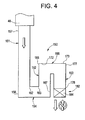
- FIG. 4 is a schematic diagram of a manometric drain in accordance with yet another exemplary embodiment of the invention.
- Turbomachine system 2 includes a turbomachine housing 4 having an interior portion 6 within which is arranged a turbomachine 10.
- Turbomachine 10 includes a compressor portion 12 that is operatively connected to a turbine portion 13 via a shaft 14 which, in turn, is connected to a generator 16 via a shaft 17.
- Compressor portion 12 includes an intake 20 that receives a flow of air through an intake system 22. Exhaust gases generated by turbomachine 10 pass from turbomachine housing 4 via an exhaust system 25.
- intake system 22 includes an intake member or duct 40 having a first end portion 42 that extends from turbomachine housing 4 to a second end portion 43 through an intermediate portion 44. Second end portion 43 is fluidly connected to a filter or filtration system 48 which, depending on geographical constraints, removes various substances such as, particulate of various sizes, moisture, and the like from the flow of air passing into intake 20.
- filter or filtration system 48 includes an inlet region 54 that receives a flow of "unclean" air, an interior or filtration region 55 for removing foreign objects/moisture, and an outlet region 56 that delivers "clean" or “filtered” air to intake 20.
- filtration system 48 includes a manometric drain system 59 positioned adjacent outlet region 56.
- Manometric drain system 59 provides a pathway for directing any trapped moisture to an exterior of filtration system 48 and away from turbomachine 10. More specifically, manometric drain system 59 allows moisture separated from the airflow passing through filtration system 48 to flow in one direction, i.e., to flow out from filtration system 48, and substantially restricts air from flowing in another direction, i.e., to flow into filtration system 48. In this manner, manometer drain system substantially limits unfiltered air bypassing filtration system 48 and entering intake 20.
- turbomachine 10 creates a low pressure area at outlet region 56 that can draw in "unclean” or “unfiltered” air through an open drain. Air passing in through the open drain bypasses particle and moisture filters and can cause damage to internal turbomachine components.
- manometric drain system 59 is designed to prevent, or at least substantially limit, the "unclean” or “unfiltered” air from entering intake member 40, bypassing filtration system 48 and potentially causing damage to turbomachine 10.
- manometric drain system 59 includes a drain box 70 having an interior portion or liquid chamber 71.
- Manometric drain system 59 further includes a first drain tube 76 and a second drain tube 77.
- Second drain tube 77 includes a first end section 80, exposed within liquid chamber 71, which extends to a second end section 81, through an intermediate section 82.
- first drain tube 76 is generally U-shaped in cross-section and includes a first substantially vertical member 87 that is fluidly connected to a second substantially vertical member 88 through a substantially horizontal member 89.
- first substantially vertical member 87 includes a first end 90, fluidly connected to filtration system 48, that extends to a second end 91.
- Substantially horizontal member 89 includes a first end 92, fluidly connected to second end 91 of first substantially vertical member 87, that extends to a second end 93.
- Second substantially vertical member 88 includes a first end 96, fluidly connected to second end 93 of substantially horizontal member 89, which extends to a second end 97 that is selectively exposed to liquid chamber 71.
- first drain tube 76 includes a one-way valve 100 arranged at second end 97 of second substantially vertical member 88.
- one-way valve 100 includes a cage 104 that houses a buoyant member such as, a check ball, 106 that selectively exposes first drain tube 76 to liquid chamber 71.
- One-way valve 100 allows moisture/fluid to pass to an exterior of filtration system 48 in one direction while preventing, or at least substantially limiting, un-filtered air from flowing in another, e.g., opposite direction and entering turbomachine 10. More specifically, when liquid chamber 71 includes a sufficient volume of liquid, second end 97 of second substantially vertical member 88 is submerged forming a trap in first drain tube 76. The trap prevents air from flowing through second drain tube 77 and entering turbomachine 10. In contrast, when an inadequate volume of liquid is present within liquid chamber 71, and a liquid trap is not possible, check ball 106 rests against second end 97 of second substantially vertical member 88 blocking flow through first drain tube 76 to prevent turbomachine 10 from ingesting un-filtered air.
- any liquid flowing from filtration system 48 will raise or float check ball 106 within cage 104 and allow the liquid to pass into liquid chamber 71.
- turbomachine 10 remains protected from foreign objects/debris/moisture.
- drain system 116 includes a drain tube 118 that is substantially U-shaped in cross-section.
- drain tube 118 includes a first substantially vertical member 120 fluidly connected to a second substantially vertical member 121 through a substantially horizontal member 122.
- First substantially vertical member 120 includes a first end 124, fluidly connected to filtration system 48, that extends to a second end 125.
- Substantially horizontal member 122 includes a first end 127, fluidly connected to second end 125 of first substantially vertical member 120, that extends to a second end 128.
- Second substantially vertical member 121 includes a first end 131, fluidly connected to second end 128 of substantially horizontal member 122, that extends to a second end 132 that is selectively exposed to a drain line (not shown). More specifically, drain tube 118 includes a one-way valve 140 arranged at second end 132 of second substantially vertical member 121.
- one-way valve 140 includes a cage 142 that houses a buoyant check ball 144.
- one-way valve 140 allows moisture/fluid to pass to an exterior of filtration system 48 in one direction while preventing, or at least substantially limiting, un-filtered air from flowing in another, e.g., opposite direction and entering turbomachine 10 via drain tube 118.
- manometric drain system 150 includes a first substantially vertical member 151 fluidly connected to a second substantially vertical member 152 and a third substantially vertical member 153 by a first substantially horizontal member 154 and a second substantially horizontal member 155 respectively. More specifically, first substantially vertical member 151 includes a first end 157, fluidly connected to filtration system 48, that extends to a second end 158. First substantially horizontal member 154 includes a first end 162, fluidly connected to second end 158 of first substantially vertical member 151, that extends to a second end 163.
- Second substantially vertical member 152 includes a first end 167 fluidly connected to second end 163 of first substantially horizontal member 154, that extends to a second end 168.
- Second substantially horizontal member 155 includes a first end 172, fluidly connected to second end portion 168 of second substantially vertical member 152, that extends to a second end 173.
- third substantially vertical member 153 includes a first end 177, fluidly connected to second end 173 of second substantially horizontal member 155, that extends to a second end 178.
- second end 178 is provided with a one-way valve 182.
- one-way valve 182 allows moisture/fluid to pass to an exterior of filtration system 48 in one direction while preventing, or at least substantially limiting, un-filtered air from flowing in another, e.g., opposite direction and entering turbomachine 10.
- one-way valve 182 comprises a mechanical check valve 184 that can take the form of a spring-biased check valve, a hydraulic check valve, a diaphragm check valve, a swing check valve or the like.
- manometric drain systems constructed in accordance with the above described exemplary embodiments are relatively maintenance free systems that require little attention to ensure proper protection for an associated turbomachine. That is, in contrast to existing systems which require regular inspection and maintenance to ensure that a sufficient volume of liquid is present within the drain system to block incoming unfiltered air.
- the above described exemplary embodiments include a one-way valve that eliminates the need for the volume of water in a drain box to prevent the ingestion of un-filtered air.
- exemplary embodiments of the invention provide a drain system that eliminates any need for a drain box.
Landscapes
- Engineering & Computer Science (AREA)
- Mechanical Engineering (AREA)
- General Engineering & Computer Science (AREA)
- Structures Of Non-Positive Displacement Pumps (AREA)
- Compressor (AREA)
- Filtering Of Dispersed Particles In Gases (AREA)
Abstract
Description
- Exemplary embodiments of the invention relate to the art of turbomachine inlet filter systems and, more particularly, to a drain for a turbomachine inlet filter system.
- Modem turbomachines include a number of rotating components that operate within tight tolerances. Foreign matter ingested into an intake of the turbomachine can cause damage, excessive wear, or even catastrophic failure. Thus, turbomachines are provided with various systems that function to remove foreign particulate from intake airstreams. In general, geographical constraints dictate particulate removal levels for the turbomachines. Turbomachines operating in a relatively dry, clean environment require a lower level of particulate removal as compared to turbomachines operating in harsh environments such as, off-shore oil rigs. In addition to removing particulate, turbomachines are provided with filtration systems that remove moisture from intake airstreams. The liquid can carry chemicals such as salts, acids and the like which could damage internal turbomachine components. Once captured, the moisture is passed to a drain and guided away from the turbomachine.
- Existing moisture systems employ a manometric drain that includes a drain box. The drain box is periodically filled with fluid (water) that forms a trap preventing a flow of unfiltered air from bypassing a filtration system and entering the turbomachine intake. More specifically, when in operation, a high velocity airflow enters the turbomachine. The high velocity airflow passes across the drain creating a pressure differential that can pull in additional, unfiltered, air thereby defeating the purpose of the filtration system. In order to prevent the backflow of air, the drain box is partially filled with water to form a trap. However, over time, the water in the drain box dissipates and requires replenishment. Unfortunately, maintenance schedules are not always strictly followed and the water in the drain box is often not replenished in time. In such situations, and despite a large capital investment in filtration systems, unfiltered air enters the turbomachine.
- In accordance with one exemplary embodiment of the invention, a turbomachine includes a compressor portion having an intake and a filtration system having an interior and an exterior. The filtration system is arranged upstream of the intake and includes a drain capable of fluid communication with the exterior of the filtration system. The drain includes a one-way valve that allows liquid separated from air flowing through the interior of the filtration system to pass through the drain to the exterior of the filtration system in a first direction, and substantially limits a flow of unfiltered air from entering the intake from the exterior in a second direction.
- In accordance with another exemplary embodiment of the invention, method of operating a turbomachine includes passing an airflow through a filtration system arranged upstream of a turbomachine intake, capturing liquid from the airflow in the filtration system, and draining the liquid from the filtration system through a drain capable of fluid communication with an exterior of the filtration system. The drain having a one-way valve that allows liquid captured by the filtration system to pass to the exterior in one direction and prevents unfiltered air from entering the turbomachine intake in another direction.
-
FIG. 1 is a schematic diagram of a turbomachine system including a manometric drain in accordance with an exemplary embodiment of the invention; -
FIG. 2 is a schematic diagram of the manometric drain ofFIG. 1 ; -
FIG. 3 is a schematic diagram of a manometric drain in accordance with another exemplary embodiment of the invention; and -
FIG. 4 is a schematic diagram of a manometric drain in accordance with yet another exemplary embodiment of the invention. - With reference to
FIG. 1 , a turbomachine system, constructed in accordance with exemplary embodiments of the invention, is indicated generally at 2.Turbomachine system 2 includes a turbomachine housing 4 having aninterior portion 6 within which is arranged aturbomachine 10.Turbomachine 10 includes acompressor portion 12 that is operatively connected to aturbine portion 13 via ashaft 14 which, in turn, is connected to agenerator 16 via ashaft 17.Compressor portion 12 includes anintake 20 that receives a flow of air through anintake system 22. Exhaust gases generated byturbomachine 10 pass from turbomachine housing 4 via anexhaust system 25. - In accordance with the exemplary embodiment shown,
intake system 22 includes an intake member orduct 40 having afirst end portion 42 that extends from turbomachine housing 4 to asecond end portion 43 through anintermediate portion 44.Second end portion 43 is fluidly connected to a filter orfiltration system 48 which, depending on geographical constraints, removes various substances such as, particulate of various sizes, moisture, and the like from the flow of air passing intointake 20. Towards that end,filtration system 48 includes aninlet region 54 that receives a flow of "unclean" air, an interior orfiltration region 55 for removing foreign objects/moisture, and anoutlet region 56 that delivers "clean" or "filtered" air to intake 20. In addition,filtration system 48 includes amanometric drain system 59 positionedadjacent outlet region 56.Manometric drain system 59 provides a pathway for directing any trapped moisture to an exterior offiltration system 48 and away fromturbomachine 10. More specifically,manometric drain system 59 allows moisture separated from the airflow passing throughfiltration system 48 to flow in one direction, i.e., to flow out fromfiltration system 48, and substantially restricts air from flowing in another direction, i.e., to flow intofiltration system 48. In this manner, manometer drain system substantially limits unfiltered airbypassing filtration system 48 and enteringintake 20. - In operation,
turbomachine 10 creates a low pressure area atoutlet region 56 that can draw in "unclean" or "unfiltered" air through an open drain. Air passing in through the open drain bypasses particle and moisture filters and can cause damage to internal turbomachine components. Thus,manometric drain system 59 is designed to prevent, or at least substantially limit, the "unclean" or "unfiltered" air from enteringintake member 40, bypassingfiltration system 48 and potentially causing damage toturbomachine 10. In accordance with one exemplary embodiment illustrated inFIG. 2 ,manometric drain system 59 includes adrain box 70 having an interior portion orliquid chamber 71.Manometric drain system 59 further includes afirst drain tube 76 and asecond drain tube 77.Second drain tube 77 includes afirst end section 80, exposed withinliquid chamber 71, which extends to asecond end section 81, through anintermediate section 82. In contrast,first drain tube 76 is generally U-shaped in cross-section and includes a first substantiallyvertical member 87 that is fluidly connected to a second substantiallyvertical member 88 through a substantiallyhorizontal member 89. - As shown, first substantially
vertical member 87 includes afirst end 90, fluidly connected tofiltration system 48, that extends to asecond end 91. Substantiallyhorizontal member 89 includes afirst end 92, fluidly connected tosecond end 91 of first substantiallyvertical member 87, that extends to asecond end 93. Second substantiallyvertical member 88 includes afirst end 96, fluidly connected tosecond end 93 of substantiallyhorizontal member 89, which extends to asecond end 97 that is selectively exposed toliquid chamber 71. More specifically,first drain tube 76 includes a one-way valve 100 arranged atsecond end 97 of second substantiallyvertical member 88. In accordance with the exemplary embodiment shown, one-way valve 100 includes acage 104 that houses a buoyant member such as, a check ball, 106 that selectively exposesfirst drain tube 76 toliquid chamber 71. - One-
way valve 100 allows moisture/fluid to pass to an exterior offiltration system 48 in one direction while preventing, or at least substantially limiting, un-filtered air from flowing in another, e.g., opposite direction and enteringturbomachine 10. More specifically, whenliquid chamber 71 includes a sufficient volume of liquid,second end 97 of second substantiallyvertical member 88 is submerged forming a trap infirst drain tube 76. The trap prevents air from flowing throughsecond drain tube 77 and enteringturbomachine 10. In contrast, when an inadequate volume of liquid is present withinliquid chamber 71, and a liquid trap is not possible,check ball 106 rests againstsecond end 97 of second substantiallyvertical member 88 blocking flow throughfirst drain tube 76 to preventturbomachine 10 from ingesting un-filtered air. Of course, any liquid flowing fromfiltration system 48 will raise or floatcheck ball 106 withincage 104 and allow the liquid to pass intoliquid chamber 71. In this manner, in the event that a maintenance schedule is missed, and an inadequate volume of water is present withinliquid chamber 71,turbomachine 10 remains protected from foreign objects/debris/moisture. - Reference will now be made to
FIG. 3 in describing amanometric drain system 116 constructed in accordance with another exemplary embodiment of the invention. As shown,drain system 116 includes adrain tube 118 that is substantially U-shaped in cross-section. In a manner similar to that described above,drain tube 118 includes a first substantiallyvertical member 120 fluidly connected to a second substantiallyvertical member 121 through a substantiallyhorizontal member 122. First substantiallyvertical member 120 includes afirst end 124, fluidly connected tofiltration system 48, that extends to asecond end 125. Substantiallyhorizontal member 122 includes afirst end 127, fluidly connected tosecond end 125 of first substantiallyvertical member 120, that extends to asecond end 128. Second substantiallyvertical member 121 includes afirst end 131, fluidly connected tosecond end 128 of substantiallyhorizontal member 122, that extends to asecond end 132 that is selectively exposed to a drain line (not shown). More specifically,drain tube 118 includes a one-way valve 140 arranged atsecond end 132 of second substantiallyvertical member 121. In accordance with the exemplary embodiment shown, one-way valve 140 includes acage 142 that houses abuoyant check ball 144. In a manner similar to that described above, one-way valve 140 allows moisture/fluid to pass to an exterior offiltration system 48 in one direction while preventing, or at least substantially limiting, un-filtered air from flowing in another, e.g., opposite direction and enteringturbomachine 10 viadrain tube 118. - Reference will now be made to
FIG. 4 in describing amanometric drain system 150 constructed in accordance with yet another exemplary embodiment of the invention. As shown,manometric drain system 150 includes a first substantiallyvertical member 151 fluidly connected to a second substantiallyvertical member 152 and a third substantiallyvertical member 153 by a first substantiallyhorizontal member 154 and a second substantiallyhorizontal member 155 respectively. More specifically, first substantiallyvertical member 151 includes afirst end 157, fluidly connected tofiltration system 48, that extends to asecond end 158. First substantiallyhorizontal member 154 includes afirst end 162, fluidly connected tosecond end 158 of first substantiallyvertical member 151, that extends to asecond end 163. Second substantiallyvertical member 152 includes afirst end 167 fluidly connected tosecond end 163 of first substantiallyhorizontal member 154, that extends to asecond end 168. Second substantiallyhorizontal member 155 includes afirst end 172, fluidly connected tosecond end portion 168 of second substantiallyvertical member 152, that extends to asecond end 173. Finally, third substantiallyvertical member 153 includes afirst end 177, fluidly connected tosecond end 173 of second substantiallyhorizontal member 155, that extends to asecond end 178. - In accordance with the exemplary embodiment illustrated in
FIG. 4 ,second end 178 is provided with a one-way valve 182. In a manner also similar to that described above, one-way valve 182 allows moisture/fluid to pass to an exterior offiltration system 48 in one direction while preventing, or at least substantially limiting, un-filtered air from flowing in another, e.g., opposite direction and enteringturbomachine 10. Towards the end, one-way valve 182 comprises amechanical check valve 184 that can take the form of a spring-biased check valve, a hydraulic check valve, a diaphragm check valve, a swing check valve or the like. - At this point it should be realized that manometric drain systems constructed in accordance with the above described exemplary embodiments are relatively maintenance free systems that require little attention to ensure proper protection for an associated turbomachine. That is, in contrast to existing systems which require regular inspection and maintenance to ensure that a sufficient volume of liquid is present within the drain system to block incoming unfiltered air. The above described exemplary embodiments include a one-way valve that eliminates the need for the volume of water in a drain box to prevent the ingestion of un-filtered air. Moreover, exemplary embodiments of the invention provide a drain system that eliminates any need for a drain box.
- In general, this written description uses examples to disclose the invention, including the best mode, and also to enable any person skilled in the art to practice the invention, including making and using any devices or systems and performing any incorporated methods. The patentable scope of the invention is defined by the claims, and may include other examples that occur to those skilled in the art. Such other examples are intended to be within the scope of exemplary embodiments of the invention if they have structural elements that do not differ from the literal language of the claims, or if they include equivalent structural elements with insubstantial differences from the literal language of the claims.
Claims (14)
- A turbomachine (10) comprising:a compressor portion (12) having an intake (20);a filtration system (48) having an interior and an exterior, the filtration system (48) being arranged upstream of the intake (20) and including a drain (59), (116), (150) capable of fluid communication with the exterior of the filtration system (44), the drain (59), (116), (150) including a one-way valve (100), (140), (182), the one-way valve (100), (140), (182) allowing liquid separated from air flowing through the interior of the filtration system (48) to pass through the drain (59), (116), (150) to the exterior of the filtration system (48) in a first direction, and substantially limiting a flow of unfiltered air from entering the intake (20) from the exterior in a second direction.
- The turbomachine (10) according to claim 1, wherein the one-way valve (100), (140) is a buoyant check ball (106), (144).
- The turbomachine (10) according to claim 2, wherein the drain (100), (140) includes a cage (104), (142), the buoyant check ball (106), (144) being arranged within the cage (104), (142).
- The turbomachine (10) according to any one of the preceding claims, wherein the one-way valve (182) is a mechanical check valve (184).
- The turbomachine (10) according to claim 4, wherein the mechanical check valve (184) is one of a spring-biased check valve, a hydraulic check valve, a diaphragm check valve and a swing arm check valve.
- The turbomachine (10) according to any one of the preceding claims, wherein the drain (59), (116), (150) comprises a manometric drain including at least one drain tube (74), (118) having a substantially U-shaped cross-section.
- The turbomachine (10) according to claim 6, wherein the at least one drain tube (118) includes a first substantially vertical member (87), (120) fluidly connected to a second substantially vertical member (87), (120) by a substantially horizontal member (89), (122), the one-way valve (100), (140) being arranged at one of the first and second substantially vertical members (87), (120), (88), (121).
- The turbomachine (10) according to claim 6, wherein the at least one drain tube (76), (118) includes a first drain tube (76) having a first exposed end (97) and a second drain tube (71) having a second exposed end (80), the first drain tube (76) having a substantially U-shaped cross-section.
- The turbomachine (10) according to claim 8, wherein each of the first and second exposed ends (97), (80) are arranged within a drain box (70).
- A method of operating a turbomachine comprising:passing an airflow through a filtration system arranged upstream of a turbomachine intake;capturing liquid from the airflow in the filtration system; anddraining the liquid from the filtration system through a drain capable of fluid communication with an exterior of the filtration system, the drain having a one-way valve, the one way valve allowing liquid captured by the filtration system to pass to the exterior in one direction and substantially limiting unfiltered air from entering the turbomachine intake in another direction.
- The method of claim 10, wherein draining the liquid from the filtration system comprises passing the liquid though at least one drain tube fluidly connected to the filtration system, the at least one drain tube including a U-shaped cross-section.
- The method of claim 10or claim 11, wherein draining the liquid from the filtration system comprises:passing the liquid though a first drain tube having a first end fluidly connected to the filtration system and a second end exposed within a drain box; andpassing the liquid through a second drain tube having a first end exposed within the drain box, the one-way valve being arranged at the second end of the first drain tube.
- The method of any one of claims 10 to 12, wherein draining the liquid from the filtration system through a one-way valve includes raising a buoyant check ball to allow the liquid to pass from the filtration system.
- The method of any one of claims 10 to 13, wherein draining the liquid from the filtration system through a one-way valve, comprises operating a mechanical valve to allow the liquid to pass from the filtration system.
Applications Claiming Priority (1)
| Application Number | Priority Date | Filing Date | Title |
|---|---|---|---|
| US12/173,960 US8133309B2 (en) | 2008-07-16 | 2008-07-16 | Turbomachine filter system having a drain with one-way valve |
Publications (2)
| Publication Number | Publication Date |
|---|---|
| EP2146099A2 true EP2146099A2 (en) | 2010-01-20 |
| EP2146099A3 EP2146099A3 (en) | 2013-04-24 |
Family
ID=41151938
Family Applications (1)
| Application Number | Title | Priority Date | Filing Date |
|---|---|---|---|
| EP09164970.7A Withdrawn EP2146099A3 (en) | 2008-07-16 | 2009-07-08 | Turbomachine filter system having a drain with one-way valve |
Country Status (4)
| Country | Link |
|---|---|
| US (1) | US8133309B2 (en) |
| EP (1) | EP2146099A3 (en) |
| CN (1) | CN101629518B (en) |
| CA (1) | CA2671463A1 (en) |
Cited By (1)
| Publication number | Priority date | Publication date | Assignee | Title |
|---|---|---|---|---|
| FR3044765A1 (en) * | 2015-12-08 | 2017-06-09 | Snecma | AIR INTAKE CHIMNEY FOR FIRM TURBOMACHINE TEST BENCH |
Families Citing this family (3)
| Publication number | Priority date | Publication date | Assignee | Title |
|---|---|---|---|---|
| US8551208B2 (en) * | 2010-11-16 | 2013-10-08 | General Electric Company | Plasma treated filter |
| US9669346B2 (en) | 2014-05-28 | 2017-06-06 | Ingersoll-Rand Company | Compressor system and oil separation system |
| US10516752B2 (en) * | 2015-06-05 | 2019-12-24 | Apple Inc. | Edge caching shared devices |
Family Cites Families (39)
| Publication number | Priority date | Publication date | Assignee | Title |
|---|---|---|---|---|
| US3912629A (en) * | 1975-01-30 | 1975-10-14 | Fuji Kinzoku Kosaku Kabushiki | Automatic drain trap |
| FR2526669A1 (en) * | 1982-05-14 | 1983-11-18 | Laguilharre Sa | DEVICE FOR SEPARATING LIQUID-VAPOR AND SIMULTANEOUSLY EXTRACTING SEPARATE LIQUID AND A LIQUID PRESENT AT ANY POINT OF AN INSTALLATION |
| DE3604090A1 (en) * | 1986-02-08 | 1987-02-26 | Daimler Benz Ag | Device on a supercharged internal combustion engine for the return of crankcase breather gases into the combustion chamber of the internal combustion engine |
| US4892569A (en) * | 1987-02-23 | 1990-01-09 | Nippon Air Brake Co., Ltd. | Compressed air pressure supply system |
| US5172714A (en) * | 1990-11-30 | 1992-12-22 | Nissan Motor Co., Ltd. | Fuel check valve assembly for fuel tank |
| ATE149952T1 (en) | 1991-07-29 | 1997-03-15 | Aka Innovative Dev | STORAGE AND DISPENSING DEVICE FOR LIQUID OR PASTY PRODUCTS |
| GB9119390D0 (en) | 1991-09-11 | 1991-10-23 | Clarke Automation Ltd | Automatic drain valve for a compressed air filter |
| JP2624587B2 (en) | 1991-10-25 | 1997-06-25 | シーケーディ株式会社 | Drain discharge device |
| US5421360A (en) * | 1993-05-07 | 1995-06-06 | Groth Corporation | Float assisted automatic driptrap |
| US5555732A (en) * | 1995-02-09 | 1996-09-17 | Whiticar; John | Portable dehumidifier |
| US5564401A (en) * | 1995-07-21 | 1996-10-15 | Diesel Research Inc. | Crankcase emission control system |
| US5715859A (en) * | 1996-10-02 | 1998-02-10 | Hunter Plumbing Products | Adjustable fill valve assembly |
| US5942105A (en) * | 1997-05-05 | 1999-08-24 | All-Glass Aquarium Company, Inc. | Float actuated water control valve |
| US6083381A (en) * | 1997-08-19 | 2000-07-04 | Donaldson Company, Inc. | Fuel filter with sediment drain valve and level indicator |
| KR19980087630A (en) * | 1998-09-03 | 1998-12-05 | 김종선 | Odor and sewage backflow blocking device of sewer |
| US5983919A (en) * | 1998-09-24 | 1999-11-16 | Drain-All, Inc. | Automatic drain valve |
| JP2000128108A (en) * | 1998-10-29 | 2000-05-09 | Shikoku Kakoki Co Ltd | Method for deaerating air in filling liquid passage in liquid filling device |
| US6338471B1 (en) * | 1998-11-18 | 2002-01-15 | Donaldson Company, Inc. | Flow control system for an evaporative cooler sump |
| FR2789127B1 (en) * | 1999-01-29 | 2001-04-20 | Framatome Sa | METHOD AND DEVICE FOR REMOVING SOIL FROM AN INTERNAL PART OF A TURBOMACHINE DURING THE OPERATION OF THE TURBOMACHINE |
| US6290845B1 (en) | 1999-02-26 | 2001-09-18 | Inetwater Llc | Water softener tank |
| JP3595728B2 (en) * | 1999-05-18 | 2004-12-02 | Smc株式会社 | Drain discharge device |
| US6161529A (en) * | 1999-06-10 | 2000-12-19 | Parker-Hannifin Corporation | Filter assembly with sump and check valve |
| ATE352706T1 (en) * | 2000-05-24 | 2007-02-15 | Parker Hannifin Corp | SAFETY SHUT-OFF VALVE FOR CRANKCASE VENTILATION CONTROL DEVICE |
| US20020092423A1 (en) * | 2000-09-05 | 2002-07-18 | Gillingham Gary R. | Methods for filtering air for a gas turbine system |
| JP2002213317A (en) | 2001-01-15 | 2002-07-31 | Wako Industrial Co Ltd | Fluid/water separator |
| SE523344C2 (en) * | 2001-03-13 | 2004-04-13 | Volvo Lastvagnar Ab | Valve device for pressure control in connection with combustion engine and method for such pressure control |
| FI5684U1 (en) | 2001-10-30 | 2003-02-13 | Uponor Innovation Ab | non-return valve |
| US6649048B2 (en) * | 2001-11-20 | 2003-11-18 | Stormwater Management | Filter cartridge with regulated surface cleaning mechanism |
| DE60219466T2 (en) | 2002-08-22 | 2008-01-03 | Perkins Engines Co. Ltd. | Combined check valve and cover for a venting device of an internal combustion engine |
| US7278259B2 (en) * | 2002-08-23 | 2007-10-09 | Donaldson Company, Inc. | Apparatus for emissions control, system, and methods |
| US7257942B2 (en) * | 2002-08-23 | 2007-08-21 | Donaldson Company, Inc. | Apparatus for emissions control, systems, and methods |
| US7204670B1 (en) * | 2002-10-07 | 2007-04-17 | Mee Industries, Inc. | Water removal from a compressor air inlet duct |
| US6907869B2 (en) * | 2003-01-17 | 2005-06-21 | Parker-Hannifin Corporation | Filter element and assembly with continuous drain |
| KR200372296Y1 (en) * | 2004-09-18 | 2005-01-10 | 주순규 | The steam trap with a hammer |
| GB2420299B (en) | 2004-11-20 | 2007-01-24 | Schlumberger Holdings | A System And Method For Flow Analysis |
| DE602004009463T2 (en) * | 2004-12-23 | 2008-07-24 | W. L. Gore & Associates Gmbh | Air filter for turbine inlet |
| US7588629B2 (en) * | 2006-01-20 | 2009-09-15 | Aaf-Mcquay Inc. | Filter cassette |
| FR2904046B1 (en) * | 2006-07-19 | 2012-11-23 | Eurocopter France | VERSATILE AIR INTAKE OF A TURBOMOTOR. |
| US20080098891A1 (en) * | 2006-10-25 | 2008-05-01 | General Electric Company | Turbine inlet air treatment apparatus |
-
2008
- 2008-07-16 US US12/173,960 patent/US8133309B2/en not_active Expired - Fee Related
-
2009
- 2009-07-08 EP EP09164970.7A patent/EP2146099A3/en not_active Withdrawn
- 2009-07-09 CA CA002671463A patent/CA2671463A1/en not_active Abandoned
- 2009-07-16 CN CN2009101616147A patent/CN101629518B/en not_active Expired - Fee Related
Cited By (1)
| Publication number | Priority date | Publication date | Assignee | Title |
|---|---|---|---|---|
| FR3044765A1 (en) * | 2015-12-08 | 2017-06-09 | Snecma | AIR INTAKE CHIMNEY FOR FIRM TURBOMACHINE TEST BENCH |
Also Published As
| Publication number | Publication date |
|---|---|
| EP2146099A3 (en) | 2013-04-24 |
| CA2671463A1 (en) | 2010-01-16 |
| US20100012562A1 (en) | 2010-01-21 |
| CN101629518B (en) | 2013-12-18 |
| US8133309B2 (en) | 2012-03-13 |
| AU2009202516A1 (en) | 2010-02-04 |
| CN101629518A (en) | 2010-01-20 |
Similar Documents
| Publication | Publication Date | Title |
|---|---|---|
| AU2009208093B2 (en) | Filtration system for gas turbines | |
| CA2675904C (en) | Filtration system for gas turbines | |
| US8133309B2 (en) | Turbomachine filter system having a drain with one-way valve | |
| US9452435B2 (en) | Separating device, an internal combustion engine and centrifugal separator assembly and a method of separating contaminants from crankcase gas | |
| CN102635444A (en) | Turbine inlet air system | |
| RU2015147198A (en) | Filtered chamber for gas turbines and a method of maintenance of the specified chamber | |
| CA2324736A1 (en) | A fuel filter and water drain system | |
| JP5930592B2 (en) | System for storing and filtering engine oil of an internal combustion engine and method for circulating and filtering engine oil of an internal combustion engine | |
| US6234137B1 (en) | Engine lubricating apparatus and method of operating an engine having such an apparatus | |
| CN212270031U (en) | Natural gas filters dirty blowdown system of collection | |
| JPH0910523A (en) | Oil filtering system equipment for lubricating oil system | |
| CN220176430U (en) | Novel lampblack treatment device | |
| JPH1136890A (en) | Drain discharge device | |
| CN212508955U (en) | Fuel tank smoke exhaust structure of steam-driven water supply pump of nuclear power station | |
| CN212715302U (en) | Integrated sewage lifting device | |
| RU2266415C1 (en) | Air-intake system of gas-transfer set with gas-turbine engine | |
| JP7637814B2 (en) | Oil-containing wastewater purification system | |
| KR101942354B1 (en) | Apparatus for treating oil mist and fume of turbocharger | |
| CZ14741U1 (en) | Separator with inclined cylindrical sieve | |
| KR101916236B1 (en) | Apparatus for treating oil mist and fume of turbocharger | |
| KR101942355B1 (en) | Apparatus for treating oil mist and fume of turbocharger | |
| CN109663445B (en) | Efficient dust haze purifier | |
| Litinetski et al. | F-technology Gas Turbine Retrofit with EPA Filters (Case Study) | |
| RU22802U1 (en) | OIL TANK OF LUBRICATION SYSTEM FOR TURBO UNITS | |
| Stanley et al. | Advances in Filtration in Automatic Lube Oil Filters |
Legal Events
| Date | Code | Title | Description |
|---|---|---|---|
| PUAI | Public reference made under article 153(3) epc to a published international application that has entered the european phase |
Free format text: ORIGINAL CODE: 0009012 |
|
| AK | Designated contracting states |
Kind code of ref document: A2 Designated state(s): AT BE BG CH CY CZ DE DK EE ES FI FR GB GR HR HU IE IS IT LI LT LU LV MC MK MT NL NO PL PT RO SE SI SK SM TR |
|
| PUAL | Search report despatched |
Free format text: ORIGINAL CODE: 0009013 |
|
| AK | Designated contracting states |
Kind code of ref document: A3 Designated state(s): AT BE BG CH CY CZ DE DK EE ES FI FR GB GR HR HU IE IS IT LI LT LU LV MC MK MT NL NO PL PT RO SE SI SK SM TR |
|
| RIC1 | Information provided on ipc code assigned before grant |
Ipc: F04D 29/70 20060101AFI20130321BHEP |
|
| 17P | Request for examination filed |
Effective date: 20131024 |
|
| RBV | Designated contracting states (corrected) |
Designated state(s): AT BE BG CH CY CZ DE DK EE ES FI FR GB GR HR HU IE IS IT LI LT LU LV MC MK MT NL NO PL PT RO SE SI SK SM TR |
|
| RAP1 | Party data changed (applicant data changed or rights of an application transferred) |
Owner name: BHA ALTAIR, LLC |
|
| 17Q | First examination report despatched |
Effective date: 20160405 |
|
| STAA | Information on the status of an ep patent application or granted ep patent |
Free format text: STATUS: THE APPLICATION IS DEEMED TO BE WITHDRAWN |
|
| 18D | Application deemed to be withdrawn |
Effective date: 20160817 |