EP2146014B1 - Height adjustable shower waste adaptor - Google Patents
Height adjustable shower waste adaptor Download PDFInfo
- Publication number
- EP2146014B1 EP2146014B1 EP09013354A EP09013354A EP2146014B1 EP 2146014 B1 EP2146014 B1 EP 2146014B1 EP 09013354 A EP09013354 A EP 09013354A EP 09013354 A EP09013354 A EP 09013354A EP 2146014 B1 EP2146014 B1 EP 2146014B1
- Authority
- EP
- European Patent Office
- Prior art keywords
- waste
- cover
- height
- cover support
- support element
- Prior art date
- Legal status (The legal status is an assumption and is not a legal conclusion. Google has not performed a legal analysis and makes no representation as to the accuracy of the status listed.)
- Active
Links
- 239000002699 waste material Substances 0.000 title claims abstract description 96
- 239000000463 material Substances 0.000 claims abstract description 23
- 239000002351 wastewater Substances 0.000 claims abstract description 22
- 238000006073 displacement reaction Methods 0.000 description 6
- 238000009408 flooring Methods 0.000 description 4
- 238000009434 installation Methods 0.000 description 3
- 230000004048 modification Effects 0.000 description 2
- 238000012986 modification Methods 0.000 description 2
- 239000002991 molded plastic Substances 0.000 description 2
- 239000004033 plastic Substances 0.000 description 2
- 229920003023 plastic Polymers 0.000 description 2
- 239000000919 ceramic Substances 0.000 description 1
- 239000011248 coating agent Substances 0.000 description 1
- 238000000576 coating method Methods 0.000 description 1
- DNJIEGIFACGWOD-UHFFFAOYSA-N ethanethiol Chemical compound CCS DNJIEGIFACGWOD-UHFFFAOYSA-N 0.000 description 1
- 239000000945 filler Substances 0.000 description 1
- 239000002184 metal Substances 0.000 description 1
- 230000000717 retained effect Effects 0.000 description 1
- 238000000926 separation method Methods 0.000 description 1
- 125000006850 spacer group Chemical group 0.000 description 1
- XLYOFNOQVPJJNP-UHFFFAOYSA-N water Substances O XLYOFNOQVPJJNP-UHFFFAOYSA-N 0.000 description 1
- 238000004804 winding Methods 0.000 description 1
Images


Classifications
-
- E—FIXED CONSTRUCTIONS
- E03—WATER SUPPLY; SEWERAGE
- E03C—DOMESTIC PLUMBING INSTALLATIONS FOR FRESH WATER OR WASTE WATER; SINKS
- E03C1/00—Domestic plumbing installations for fresh water or waste water; Sinks
- E03C1/12—Plumbing installations for waste water; Basins or fountains connected thereto; Sinks
- E03C1/22—Outlet devices mounted in basins, baths, or sinks
-
- E—FIXED CONSTRUCTIONS
- E03—WATER SUPPLY; SEWERAGE
- E03F—SEWERS; CESSPOOLS
- E03F5/00—Sewerage structures
- E03F5/04—Gullies inlets, road sinks, floor drains with or without odour seals or sediment traps
- E03F5/0407—Floor drains for indoor use
- E03F5/0408—Floor drains for indoor use specially adapted for showers
-
- E—FIXED CONSTRUCTIONS
- E03—WATER SUPPLY; SEWERAGE
- E03F—SEWERS; CESSPOOLS
- E03F5/00—Sewerage structures
- E03F5/04—Gullies inlets, road sinks, floor drains with or without odour seals or sediment traps
-
- E—FIXED CONSTRUCTIONS
- E03—WATER SUPPLY; SEWERAGE
- E03F—SEWERS; CESSPOOLS
- E03F5/00—Sewerage structures
- E03F5/04—Gullies inlets, road sinks, floor drains with or without odour seals or sediment traps
- E03F5/0407—Floor drains for indoor use
- E03F5/0409—Devices for preventing seepage around the floor drain
-
- E—FIXED CONSTRUCTIONS
- E03—WATER SUPPLY; SEWERAGE
- E03F—SEWERS; CESSPOOLS
- E03F5/00—Sewerage structures
- E03F5/04—Gullies inlets, road sinks, floor drains with or without odour seals or sediment traps
- E03F2005/0412—Gullies inlets, road sinks, floor drains with or without odour seals or sediment traps with means for adjusting their position with respect to the surrounding surface
- E03F2005/0413—Gullies inlets, road sinks, floor drains with or without odour seals or sediment traps with means for adjusting their position with respect to the surrounding surface for height adjustment
Definitions
- This invention relates to a height-adjustable shower waste and, more particularly but not exclusively, to a shower waste for clamping flexible waterproof floor covering material which can be adapted to provide a height-adjustable cover when used with non-flexible waterproof floor covering material, such as tiles.
- Height-adjustable interior floor wastes are known from Jay R Smith Mfg. Co. of Montgomery, Alabama, USA. These provide a waste body which can be recessed into a floor and which is connectable to a drain, a grid cover for waste water to pass into the waste body, and a cover support which is screw-threadingly engaged with the waste body to enable height-adjustment of the grid cover relative to the waste body.
- a height-adjustable shower or bathroom floor waste is also known from Impey UK Ltd of Ilton, Somerset, United Kingdom. This provides a waste body which is supported in a floor, a grid cover, and a cover support having a generally serrated or multi-ramped lower edge. Complementarily angled surfaces are provided on the waste body and on which the cover support sits. As the grid cover support is rotated in the waste body, the abutting ramp surfaces slide relative to each other, causing the cover support to telescopically extend or retract.
- the cover support of the Impey floor waste is not vertically engaged with the waste body, it is only seated in the waste body to slide on the ramped surfaces. Thus, the cover support is easily dislodged or removed from the waste body.
- a further problem associated with the latter known arrangement is that, although the grid cover is removable from the cover support to permit access into the interior of the waste body, once the waste is installed, the height of the cover support from the base of the waste body can no longer be precisely adjusted and set rigidly in position prior to the flooring being installed. This follows from the fact that, when finishing the floor, either with concrete screed or tiles, the floor extends up to and abuts the cover support adjacent to the cover grid. Further height adjustment cannot reliably take place to compensate for changes in finished floor levels at the time of installation of the flooring material, typically tiles.
- US-A-4883590 describes a height-adjustable floor drain comprising a waste body for mounting in the bathroom floor and a cover support element on which a cover element is provided to cover the waste water inlet.
- the drain further comprises distance setting means for selectively setting a distance between an in use upper edge of the cover support element and the waste body, the distance setting means comprising an arcuate rib which is provided on the cover support element, and a screw-thread on the waste body.
- the arcuate rib is movable alone the screw-thread to alter the distance between the upper edge of the support element and the waste body.
- the floor drain comprises retaining means in the form of a screw for positively retaining the cover support element at the set distance.
- the present invention seeks to provide a solution to these problems.
- a height-adjustable shower waste for use with a flexible waterproof floor covering, the shower waste, comprising a waste body having a waste water inlet and a waste water outlet connected to or connectable to a drain, a cover support element on which a cover element is or can be provided to cover the waste water inlet; an adaptor element for connection to the flexible waterproof floor covering shower waste and for supporting the cover support element; distance setting means for selectively setting a distance between an in use upper edge of the cover support element and the adaptor element; the distance setting means comprising an arcuate rib which is provided on one of the cover support element or the adaptor element, and a screw-thread on the other one of the cover support element and the adaptor element, the arcuate rib being movable along the screw-thread to alter the distance between the upper edge of the support element and the adaptor element; and retaining means for positively retaining the cover support at the said set distance, said retaining means comprising at least one locking element which is provided on one of the cover
- Such a waste hereinbefore so described may also beneficially be installed as part of a tanked floor installation which incorporates a painted or sprayed or similarly applied elastomeric or ruberiod compliant coating to present a secondary impermeable seal below a non-flexible waterproof flooring material.
- a height-adjustable shower waste 10 which comprises a waste body 12, a clamp ring adapter element 14, a cover support element 16 telescopically supported in the waste body 12, and a cover element 18 in the form of a grid and provided on the cover support element 16.
- the waste body 12 is typically formed from moulded plastics material and has a base 20, a circular wall 22 extending in use upwardly from the base 20, an endless upper flange 24 formed to extend outwardly from a distal edge of the circular wall 22 in or substantially in parallel with and opposite to the base 20, a waste water inlet 26 opposite the base 20 and defined by an upper surface 28 of the waste body 12, and a waste water outlet 30 formed in the base 20 and opposite the waste water inlet 26.
- the circular wall 22 has a stepped interior surface 32 between the upper flange 24 and the base 20.
- the upper flange 24 includes angularly spaced apertures 34 extending therethrough or guides for screw-threaded fasteners for fastening the waste body 12 to a floor surface.
- the stepped interior surface 32 has an endless and unbroken frusto-conical clamping portion 36 which tapers in a converging direction away from the upper surface 28.
- An endless clamp support portion 38 extends radially inwardly and in parallel with the upper flange 24 from a lower edge of the frusto-conical clamping portion 36.
- the clamp support portion 38 includes a plurality of angularly spaced, typically threaded, recesses or apertures 40 for receiving screw-threaded fasteners 42.
- An endless and unbroken frusto-conical sump portion 44 extends from a radially inner edge of the clamp support portion 38.
- the sump portion 44 tapers in a converging direction to meet the base 20.
- the waste body 12 described above is adapted to enable clamping of, typically cold weldable, flexible waterproof floor covering material, such as Altro RTM.
- an endless clamp ring (not shown) can be provided.
- the clamp ring has an endless and unbroken frusto-conical clamping wall, and an endless engagement flange which projects radially inwardly from one edge of the clamping wall.
- the frusto-conical clamping wall tapers in a converging direction to meet the engagement flange, and angularly spaced openings or guides are provided on or through only the engagement flange to receive screw-threaded fasteners.
- the dimensions of the clamp ring are such that the engagement flange can be seated on the clamp support portion 38, and engaged using screw-threaded fasteners 42 inserted in the openings or guides and engaged in the recesses or apertures 40 of the clamp support portion 38.
- the clamping wall of the clamp ring When seated on the clamp support portion 38, the clamping wall of the clamp ring extends in or substantially in parallel with, and is slightly spaced radially inwardly from, the clamping portion 36 of the waste body 12. Consequently, in use, the flexible floor covering material is cut to extend into the bore and along only the clamping portion 36.
- the clamp ring when fastened to the clamp support portion 38, thus tightly clamps the flexible floor covering material to the clamping portion 36 of the waste body 12 via its clamping wall.
- the flexible floor covering material is not perforated, and thus no leak path is produced.
- the clamp ring adapter element 14 is provided to replace the clamp ring.
- the adapter element 14 has an endless, typically plastics moulded, ring shaped generally cylindrical adapter body 46 defining a circular through-bore 48 through which waste water can flow, and an endless adapter flange 50 which extends radially outwardly from one edge of the adapter body 46.
- Diametrically opposed openings 52 are formed through the adapter body 46 in parallel with the through-bore 48 to receive screw-threaded fasteners 42.
- a screw-thread 54 forming part of distance setting means for the cover support element 16, is integrally formed in the surface of the through-bore 48 of the adapter element 14, from one end to the other.
- the adapter body 46 is dimensioned to sit on the clamp support portion 38 of the interior surface 32 of the waste body 12. When seated, the adapter flange 50 is coplanar or substantially coplanar with the upper flange 24 of the waste body 12. Screw-threaded fasteners 42 are located in the openings 52 of the adapter body 46, and received in the corresponding apertures or recesses 40 in the clamp support portion 38. In this way, the adapter body 46 can be securely engaged with waste body 12.
- the cover support element 16 comprises an adapter engaging part 56 and a cover element support part 58.
- the engaging part 56 is typically formed from moulded plastics and has an endless ring-shaped cylindrical engaging body 60, axially extending slots 62 formed in an in use upper edge of the engaging body 60, an inwardly extending lip 64 formed on an inner surface of the engaging body 60 at or adjacent to the upper edge, and an arcuate rib 66 formed generally circumferentially on its outer surface, partway between the ends of the engaging body 60.
- the arcuate rib 66 forms another part of the distance setting means and projects radially outwardly from the outer surface of the engaging body 60. As understood from Figures 2 and 3 , the arcuate rib 66 is not continuous, and the ends 68 are spaced in an axial direction of the engaging part 56 to provide a pitch which matches that of the screw-thread 54 formed in the through-bore 48 of the adapter element 14.
- the arcuate rib 66 extends 360° around the engaging body 60, but may extend less than or more than 360°.
- the arcuate rib can be formed as multiple full and partial revolutions around the body 60.
- the cover element support part 58 of the cover support element 16 is typically formed from metal or plastics material and includes a cover element tray 70 integrally formed with a cylindrical wall 72 which extends perpendicularly to the plane of the tray 70.
- the tray 70 includes a recessed portion 74, a raised border 76 surrounding the recessed portion 74, and an upstanding edge 78 formed around the perimeter of the raised border 76.
- An endless outwardly projecting inverted U-shaped first lip 80 is formed to extend from the upstanding edge 78.
- the recessed portion 74 of the tray 70 is formed with a central aperture 82, and the cylindrical wall 72 extends endlessly around the aperture from a lower surface of the recessed portion 74.
- the upstanding edge 78 is dimensioned to removably accept the cover element 18 as a close fit.
- an upper surface 84 of the cover element 18 is coplanar or substantially coplanar with an upper surface 86 of the outwardly projecting first lip 80.
- An endless outwardly projecting second lip 88 is formed at or adjacent to the distal end of the cylindrical wall 72, remote from the tray 70.
- the adapter engaging part 56 and the cover element support part 58 are snap-fit engageable by pushing the cylindrical wall 72 into the cylindrical engaging body 60.
- the slots 62 allow the engaging body 60 to flex as the inwardly extending lip 64 of the engaging body 60 rides over the outwardly projecting second lip 88 of the cylindrical wall 72.
- the engaging part 56 and the cover element support part 58 are tightly fastened relative to each other, making axial separation difficult, but not impossible.
- the engagement between the two parts is such that relative angular displacement can only occur when one part is forcibly restrained while the other part is rotated.
- the cover support element 16 can thus be screw-threadingly engaged with the adapter element 14.
- the arcuate rib 66 projects outwardly to engage the screw-thread 54 (see Figure 5 ) formed along the through-bore 48 of the adapter body 46.
- the arcuate rib 66 moves along the screw-thread 54 ( Figures 7 and 8 ), thus causing the tray 70 of the cover support element 16, and consequently the cover element 18 when provided thereon, to move towards or away from the adapter element 14.
- Retaining means is provided to releasably retain the cover support element 16 at a selected position relative to the adapter element 14.
- the retaining means comprises a tab element 90 which is slidably received in a tab slot 92 formed in the adapter body 46 and adapter flange 50.
- the tab slot 92 extends from the bore of the adapter element 14 and radially outwards along the adapter flange 50, terminating prior to the perimeter edge of the adapter flange 50.
- the tab element 90 is generally pistol-shaped having a tab body 94, a runner 96 depending from an in use lower edge of the tab body 94, and a tab notch 98 formed in an upper edge opposite the lower edge.
- a runner slot 100 is formed in the base of the tab slot 92 to slidably receive a reduced thickness web portion 102 of the runner 96.
- the tab notch 98 is accessible from the adapter flange 50 to move the tab element 90 radially into and out of the through-bore 48 of the adapter element 14 ( Figures 6 to 9 ).
- the tab element 90 can be biased, for example via a spring element, to project into the through-bore 48 of the adapter element 14.
- the retaining means also includes a plurality of tab element recesses 104 formed at preferably, but not necessarily, equi-angularly spaced intervals along the longitudinal extent of the arcuate rib 66 of the cover support element 16.
- the tab element recesses 104 are spaced to allow a variation in distance from the cover element 18, when provided on the tray 70 of the cover support element 16, to the upper flange 24 of the waste body 12 of between 4 mm to 16 mm. This range is suggested, since this accommodates all common thicknesses of ceramic tile. However, other distances are entirely feasible.
- the tab element recesses 104 are dimensioned to receive a radially inner edge of the in use tab element 90, as can be seen in Figures 6 and 9 .
- the waste body 12 In use, once it has been determined where the waste should be sited, the waste body 12 is recessed into the existing floor, ideally located in a wet floor former as typified in GB2401341A or by making a suitably sized hole in concrete flooring or by removing portions of floorboards.
- the waste water outlet 30 of the waste body 12 is connected to the drain, optionally via a pump.
- waste body 12, flange 24 and frusto-conical clamping portion 36 and the associated support surface 38 describes known prior art used extensively in flexible wet floor material clamp type waste drains of a wide variety of types. Accordingly, the single example of a waste with a simple outlet 30 so described to accommodate the present invention is understood to include all derivatives of such waste discharges which may optionally include stench water traps or be of the pumped waste arrangement without detracting from the uniqueness of said invention.
- the clamp ring is dispensed with, and the adapter element 14 is fastened in the waste water inlet 26 of the waste body 12 via screw-threaded fasteners, as described above.
- the tab element 90 is inserted into the tab slot 92, in a retracted condition.
- the adapter engaging part 56 and the cover element support part 58 of the cover support element 16 are snap-fittably engaged, again as described above, and the cover support element 16 is then screw-threadingly engaged in the through-bore 48 of the adapter element 14 by winding the arcuate rib 66 along the screw-thread 54 of the adapter element 14.
- Waterproof non-flexible floor covering material such as tiles, is then positioned on the floor adjacent to the waste 10.
- the plane of the upper surface of the non-flexible floor covering material is determined, and the cover support element 16 is rotated ( Figures 7 and 8 ) until the outwardly extending first lip 80 on the cover support element 16 becomes coplanar or substantially coplanar.
- the tab element 90 is urged via the tab notch 98 to project into the through-bore 48 of the adapter element 14 and to engage in one of the tab element recesses 104 on the arcuate rib 66 of the cover support element 16 ( Figure 9 ).
- the cover support element 16 is thus locked or retained in position, and as such is prevented from further moving vertically relative to the waste body 12.
- the cover element support part 58 can, with some effort, still be annularly rotated to simplify alignment with the non-flexible floor covering material.
- the non-flexible floor covering material is extended up to and under the outwardly extending first lip 80 of the tray 70, thus covering the tab element 90, as will be understood from Figure 1 .
- the cover element 18 can then be placed in the tray 70. Since the cover element 18 is a grid, waste water will run across the non-flexible floor covering material and enter the waste body 12 through the cover element 18 and the cover support element 16.
- the clamp ring adaptor element, the cover support element, and a cover element can be provided as a height-adjustable shower waste adaptor device for use in combination with the waste body of the flexible waterproof floor covering shower waste.
- the existing flexible waterproof floor covering material can then be replaced with non-flexible waterproof floor covering material.
- the tab element is accessed and retracted, the cover element is lifted out of the tray, and, by reaching inside, the adaptor element engaging part can be rotated to lift or lower the cover element support part relative to the waste body and the surrounding floor surface. In this way, only a small portion of the non-flexible floor covering material need be removed to access the tab element, since the cover element support part need not be rotated in order to achieve vertical displacement.
- the cover element could be formed without apertures. In this case, waste water flows into the waste body through a gap provided between the perimeter edge of the cover element and the cover support element.
- the waste water outlet can be formed in the wall of the bore, rather than in the base.
- non-flexible waterproof floor covering material can be positioned up to the edge of the cover support element, it may only be adjacent to the edge with grouting or other suitable filler being used to bridge a small gap or gaps therebetween.
- the wall of the waste body is circular, but may be non-circular and can includes more than one contiguous wall or side.
- the arcuate rib is the sole arcuate rib. However, two or more arcuate ribs can be provided in axially spaced relationship.
- a plurality of arcuate ribs can be provided in spaced relationship in the longitudinal direction of the ribs.
- the tab element recesses can be provided as spaces between the plurality of arcuate ribs, such that the arcuate ribs are spaced from each other.
- the tab element is slidably movable.
- other kinds of tab element are envisaged, such as a rotatable or pivotable tab element which is movable by angular displacement to engage or disengage the cover support element and/or the waste body or clamp ring adaptor element.
- the cover support element is a two part element. However, the cover support element can be formed as a single part.
- the cover support element can include more than two parts, whereby spacer elements are provided for interposable engagement between the adapter engaging part and the cover element support part in order to provide additional provision to further vary the height of the tray above the waste body.
- a shower waste with a cover which is height-adjustable. It is also possible to provide a shower waste which prevents or limits further vertical height-adjustment or vertical movement once the height has been set.
- a cover support element can be provided which does allow relative angular displacement of the cover, even when the height has been set and locked. It is also possible to provide an adaptor device which can adapt an existing flexible wet-floor clamping shower waste for use with a non-flexible floor covering, so as to provide an adjustable-height cover.
Landscapes
- Engineering & Computer Science (AREA)
- Health & Medical Sciences (AREA)
- Life Sciences & Earth Sciences (AREA)
- Hydrology & Water Resources (AREA)
- Public Health (AREA)
- Water Supply & Treatment (AREA)
- Environmental & Geological Engineering (AREA)
- Sink And Installation For Waste Water (AREA)
- Treatment Of Fiber Materials (AREA)
- Treatment Of Sludge (AREA)
- Bathtubs, Showers, And Their Attachments (AREA)
- Floor Finish (AREA)
- Processing Of Meat And Fish (AREA)
- Nozzles (AREA)
- Massaging Devices (AREA)
Abstract
Description
- This invention relates to a height-adjustable shower waste and, more particularly but not exclusively, to a shower waste for clamping flexible waterproof floor covering material which can be adapted to provide a height-adjustable cover when used with non-flexible waterproof floor covering material, such as tiles.
- Height-adjustable interior floor wastes are known from Jay R Smith Mfg. Co. of Montgomery, Alabama, USA. These provide a waste body which can be recessed into a floor and which is connectable to a drain, a grid cover for waste water to pass into the waste body, and a cover support which is screw-threadingly engaged with the waste body to enable height-adjustment of the grid cover relative to the waste body.
- A height-adjustable shower or bathroom floor waste is also known from Impey UK Ltd of Ilton, Somerset, United Kingdom. This provides a waste body which is supported in a floor, a grid cover, and a cover support having a generally serrated or multi-ramped lower edge. Complementarily angled surfaces are provided on the waste body and on which the cover support sits. As the grid cover support is rotated in the waste body, the abutting ramp surfaces slide relative to each other, causing the cover support to telescopically extend or retract.
- The problems associated with both of these arrangements is that, once the height of the cover has been adjusted and set, there is no means for preventing the height again changing, such as through use or by people inadvertently scuffing or knocking the cover grid.
- Furthermore, the cover support of the Impey floor waste is not vertically engaged with the waste body, it is only seated in the waste body to slide on the ramped surfaces. Thus, the cover support is easily dislodged or removed from the waste body.
- A further problem associated with the latter known arrangement is that, although the grid cover is removable from the cover support to permit access into the interior of the waste body, once the waste is installed, the height of the cover support from the base of the waste body can no longer be precisely adjusted and set rigidly in position prior to the flooring being installed. This follows from the fact that, when finishing the floor, either with concrete screed or tiles, the floor extends up to and abuts the cover support adjacent to the cover grid. Further height adjustment cannot reliably take place to compensate for changes in finished floor levels at the time of installation of the flooring material, typically tiles.
- Other vertically adjustable floor drain apparatus are described in
US4883590 ,GB1014814 US1873275 . For example,US-A-4883590 describes a height-adjustable floor drain comprising a waste body for mounting in the bathroom floor and a cover support element on which a cover element is provided to cover the waste water inlet. The drain further comprises distance setting means for selectively setting a distance between an in use upper edge of the cover support element and the waste body, the distance setting means comprising an arcuate rib which is provided on the cover support element, and a screw-thread on the waste body. The arcuate rib is movable alone the screw-thread to alter the distance between the upper edge of the support element and the waste body. Furthermore, the floor drain comprises retaining means in the form of a screw for positively retaining the cover support element at the set distance. - However, it is cumbersome to fix the screw since access to the interior of the floor drain is limited.
- The present invention seeks to provide a solution to these problems.
- According to the present invention, there is provided a height-adjustable shower waste for use with a flexible waterproof floor covering, the shower waste, comprising a waste body having a waste water inlet and a waste water outlet connected to or connectable to a drain, a cover support element on which a cover element is or can be provided to cover the waste water inlet; an adaptor element for connection to the flexible waterproof floor covering shower waste and for supporting the cover support element; distance setting means for selectively setting a distance between an in use upper edge of the cover support element and the adaptor element; the distance setting means comprising an arcuate rib which is provided on one of the cover support element or the adaptor element, and a screw-thread on the other one of the cover support element and the adaptor element, the arcuate rib being movable along the screw-thread to alter the distance between the upper edge of the support element and the adaptor element; and retaining means for positively retaining the cover support at the said set distance, said retaining means comprising at least one locking element which is provided on one of the cover support element and the adaptor element and which is moveable between a locked position at which the distance between the cover element and the adaptor element is fixed, and an unlocked position at which the position between the cover element and the adaptor element is adjustable, characterised in that the locking element is a locking tab element and the retaining means further comprises a plurality of spaced recesses which are provided on the other one of the cover support element and the adaptor element and in which the locking tab element is receivable to hold the upper edge of the cover support element at a fixed distance from the adaptor element.
- Preferable and/or optional features of the first aspect of the invention are set forth in claims 2 to 11, inclusive.
- Such a waste hereinbefore so described may also beneficially be installed as part of a tanked floor installation which incorporates a painted or sprayed or similarly applied elastomeric or ruberiod compliant coating to present a secondary impermeable seal below a non-flexible waterproof flooring material.
- The present invention will now be more particularly described, by way of example only, with reference to the accompanying drawings, in which :
-
Figure 1 is a perspective view of one embodiment of a height-adjustable shower waste, in accordance with the invention and which is in the form of a flexible waterproof floor covering shower waste adapted by use of an adjustable-height shower waste adaptor according to the invention; -
Figure 2 is an exploded view of the waste shown inFigure 1 ; -
Figure 3 is a perspective view of part of a cover support element shown inFigure 2 , but from another side; -
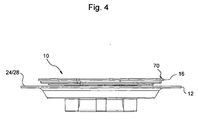
Figure 4 is a side elevational view of the waste shown inFigure 1 ; -
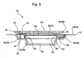
Figure 5 is a cross-sectional view of the waste shown inFigure 4 ; -
Figure 6 is a partially sectioned, enlarged scrap view showing the cover support element, cover element, and a tab element of retaining means of the waste and adaptor; -
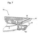
Figure 7 is a view similar toFigure 6 , showing the tab element in a retracted condition; -
Figure 8 is a view similar toFigures 6 and7 , showing the cover support element in a raised condition, with the tab element still retracted; and -
Figure 9 is a view similar toFigures 6 to 8 , showing the tab element in a projecting condition and locking the cover support element. - Referring to the drawings, there is shown a height-
adjustable shower waste 10 which comprises awaste body 12, a clampring adapter element 14, acover support element 16 telescopically supported in thewaste body 12, and acover element 18 in the form of a grid and provided on thecover support element 16. - The
waste body 12 is typically formed from moulded plastics material and has abase 20, acircular wall 22 extending in use upwardly from thebase 20, an endlessupper flange 24 formed to extend outwardly from a distal edge of thecircular wall 22 in or substantially in parallel with and opposite to thebase 20, awaste water inlet 26 opposite thebase 20 and defined by anupper surface 28 of thewaste body 12, and awaste water outlet 30 formed in thebase 20 and opposite thewaste water inlet 26. Thecircular wall 22 has a steppedinterior surface 32 between theupper flange 24 and thebase 20. - The
upper flange 24 includes angularly spacedapertures 34 extending therethrough or guides for screw-threaded fasteners for fastening thewaste body 12 to a floor surface. - The stepped
interior surface 32 has an endless and unbroken frusto-conical clamping portion 36 which tapers in a converging direction away from theupper surface 28. An endlessclamp support portion 38 extends radially inwardly and in parallel with theupper flange 24 from a lower edge of the frusto-conical clamping portion 36. Theclamp support portion 38 includes a plurality of angularly spaced, typically threaded, recesses orapertures 40 for receiving screw-threadedfasteners 42. - An endless and unbroken frusto-
conical sump portion 44 extends from a radially inner edge of theclamp support portion 38. Thesump portion 44 tapers in a converging direction to meet thebase 20. - The
waste body 12 described above is adapted to enable clamping of, typically cold weldable, flexible waterproof floor covering material, such as Altro RTM. To this end, an endless clamp ring (not shown) can be provided. The clamp ring has an endless and unbroken frusto-conical clamping wall, and an endless engagement flange which projects radially inwardly from one edge of the clamping wall. The frusto-conical clamping wall tapers in a converging direction to meet the engagement flange, and angularly spaced openings or guides are provided on or through only the engagement flange to receive screw-threaded fasteners. - The dimensions of the clamp ring are such that the engagement flange can be seated on the
clamp support portion 38, and engaged using screw-threadedfasteners 42 inserted in the openings or guides and engaged in the recesses orapertures 40 of theclamp support portion 38. - When seated on the
clamp support portion 38, the clamping wall of the clamp ring extends in or substantially in parallel with, and is slightly spaced radially inwardly from, the clampingportion 36 of thewaste body 12. Consequently, in use, the flexible floor covering material is cut to extend into the bore and along only the clampingportion 36. The clamp ring, when fastened to theclamp support portion 38, thus tightly clamps the flexible floor covering material to the clampingportion 36 of thewaste body 12 via its clamping wall. The flexible floor covering material is not perforated, and thus no leak path is produced. - However, when it is desirable to use a non-flexible waterproof floor covering material, such as tiles, the clamp ring cannot be utilised.
- In this case, the clamp
ring adapter element 14 is provided to replace the clamp ring. As best seen inFigure 2 , theadapter element 14 has an endless, typically plastics moulded, ring shaped generally cylindrical adapter body 46 defining a circular through-bore 48 through which waste water can flow, and anendless adapter flange 50 which extends radially outwardly from one edge of the adapter body 46. Diametrically opposedopenings 52 are formed through the adapter body 46 in parallel with the through-bore 48 to receive screw-threadedfasteners 42. - A screw-
thread 54, forming part of distance setting means for thecover support element 16, is integrally formed in the surface of the through-bore 48 of theadapter element 14, from one end to the other. - The adapter body 46 is dimensioned to sit on the
clamp support portion 38 of theinterior surface 32 of thewaste body 12. When seated, theadapter flange 50 is coplanar or substantially coplanar with theupper flange 24 of thewaste body 12. Screw-threadedfasteners 42 are located in theopenings 52 of the adapter body 46, and received in the corresponding apertures or recesses 40 in theclamp support portion 38. In this way, the adapter body 46 can be securely engaged withwaste body 12. - The
cover support element 16 comprises anadapter engaging part 56 and a coverelement support part 58. Theengaging part 56 is typically formed from moulded plastics and has an endless ring-shaped cylindrical engaging body 60, axially extendingslots 62 formed in an in use upper edge of the engaging body 60, an inwardly extendinglip 64 formed on an inner surface of the engaging body 60 at or adjacent to the upper edge, and anarcuate rib 66 formed generally circumferentially on its outer surface, partway between the ends of the engaging body 60. - The
arcuate rib 66 forms another part of the distance setting means and projects radially outwardly from the outer surface of the engaging body 60. As understood fromFigures 2 and3 , thearcuate rib 66 is not continuous, and theends 68 are spaced in an axial direction of theengaging part 56 to provide a pitch which matches that of the screw-thread 54 formed in the through-bore 48 of theadapter element 14. - The
arcuate rib 66 extends 360° around the engaging body 60, but may extend less than or more than 360°. - Although more complicated, the arcuate rib can be formed as multiple full and partial revolutions around the body 60.
- The cover
element support part 58 of thecover support element 16 is typically formed from metal or plastics material and includes acover element tray 70 integrally formed with acylindrical wall 72 which extends perpendicularly to the plane of thetray 70. - The
tray 70 includes a recessedportion 74, a raisedborder 76 surrounding the recessedportion 74, and anupstanding edge 78 formed around the perimeter of the raisedborder 76. An endless outwardly projecting inverted U-shapedfirst lip 80 is formed to extend from theupstanding edge 78. - The recessed
portion 74 of thetray 70 is formed with acentral aperture 82, and thecylindrical wall 72 extends endlessly around the aperture from a lower surface of the recessedportion 74. - The
upstanding edge 78 is dimensioned to removably accept thecover element 18 as a close fit. When supported by thetray 70, anupper surface 84 of thecover element 18 is coplanar or substantially coplanar with anupper surface 86 of the outwardly projectingfirst lip 80. - An endless outwardly projecting
second lip 88 is formed at or adjacent to the distal end of thecylindrical wall 72, remote from thetray 70. - The
adapter engaging part 56 and the coverelement support part 58 are snap-fit engageable by pushing thecylindrical wall 72 into the cylindrical engaging body 60. Theslots 62 allow the engaging body 60 to flex as the inwardly extendinglip 64 of the engaging body 60 rides over the outwardly projectingsecond lip 88 of thecylindrical wall 72. Once connected, the engagingpart 56 and the coverelement support part 58 are tightly fastened relative to each other, making axial separation difficult, but not impossible. Furthermore, although relative angular displacement of theengaging part 56 and the coverelement support part 58 is possible by hand, the engagement between the two parts is such that relative angular displacement can only occur when one part is forcibly restrained while the other part is rotated. - It will be understood that, when the engaging
part 56 or the coversupport element part 58 is subjected to only a rotating force which rotates one part relative to the other part, there is no relative axial displacement of the two parts. - The
cover support element 16 can thus be screw-threadingly engaged with theadapter element 14. Thearcuate rib 66 projects outwardly to engage the screw-thread 54 (seeFigure 5 ) formed along the through-bore 48 of the adapter body 46. As thecover support element 16 is rotated, thearcuate rib 66 moves along the screw-thread 54 (Figures 7 and8 ), thus causing thetray 70 of thecover support element 16, and consequently thecover element 18 when provided thereon, to move towards or away from theadapter element 14. - Retaining means is provided to releasably retain the
cover support element 16 at a selected position relative to theadapter element 14. The retaining means comprises atab element 90 which is slidably received in atab slot 92 formed in the adapter body 46 andadapter flange 50. Thetab slot 92 extends from the bore of theadapter element 14 and radially outwards along theadapter flange 50, terminating prior to the perimeter edge of theadapter flange 50. - The
tab element 90 is generally pistol-shaped having atab body 94, arunner 96 depending from an in use lower edge of thetab body 94, and atab notch 98 formed in an upper edge opposite the lower edge. Arunner slot 100 is formed in the base of thetab slot 92 to slidably receive a reducedthickness web portion 102 of therunner 96. Thetab notch 98 is accessible from theadapter flange 50 to move thetab element 90 radially into and out of the through-bore 48 of the adapter element 14 (Figures 6 to 9 ). - Although not biased, the
tab element 90 can be biased, for example via a spring element, to project into the through-bore 48 of theadapter element 14. - The retaining means also includes a plurality of tab element recesses 104 formed at preferably, but not necessarily, equi-angularly spaced intervals along the longitudinal extent of the
arcuate rib 66 of thecover support element 16. The tab element recesses 104 are spaced to allow a variation in distance from thecover element 18, when provided on thetray 70 of thecover support element 16, to theupper flange 24 of thewaste body 12 of between 4 mm to 16 mm. This range is suggested, since this accommodates all common thicknesses of ceramic tile. However, other distances are entirely feasible. - The tab element recesses 104 are dimensioned to receive a radially inner edge of the in
use tab element 90, as can be seen inFigures 6 and9 . - In use, once it has been determined where the waste should be sited, the
waste body 12 is recessed into the existing floor, ideally located in a wet floor former as typified inGB2401341A waste water outlet 30 of thewaste body 12 is connected to the drain, optionally via a pump. - It will be evident to those skilled in the art that the arrangement of
waste body 12,flange 24 and frusto-conical clamping portion 36 and the associatedsupport surface 38 describes known prior art used extensively in flexible wet floor material clamp type waste drains of a wide variety of types. Accordingly, the single example of a waste with asimple outlet 30 so described to accommodate the present invention is understood to include all derivatives of such waste discharges which may optionally include stench water traps or be of the pumped waste arrangement without detracting from the uniqueness of said invention. - The clamp ring is dispensed with, and the
adapter element 14 is fastened in thewaste water inlet 26 of thewaste body 12 via screw-threaded fasteners, as described above. Thetab element 90 is inserted into thetab slot 92, in a retracted condition. Theadapter engaging part 56 and the coverelement support part 58 of thecover support element 16 are snap-fittably engaged, again as described above, and thecover support element 16 is then screw-threadingly engaged in the through-bore 48 of theadapter element 14 by winding thearcuate rib 66 along the screw-thread 54 of theadapter element 14. - Waterproof non-flexible floor covering material, such as tiles, is then positioned on the floor adjacent to the
waste 10. The plane of the upper surface of the non-flexible floor covering material is determined, and thecover support element 16 is rotated (Figures 7 and8 ) until the outwardly extendingfirst lip 80 on thecover support element 16 becomes coplanar or substantially coplanar. - Once the distance of the
tray 70 of thecover support element 16, and thus thecover element 18 itself, from thewaste body 12 has been set, thetab element 90 is urged via thetab notch 98 to project into the through-bore 48 of theadapter element 14 and to engage in one of the tab element recesses 104 on thearcuate rib 66 of the cover support element 16 (Figure 9 ). Thecover support element 16 is thus locked or retained in position, and as such is prevented from further moving vertically relative to thewaste body 12. - The cover
element support part 58, however, can, with some effort, still be annularly rotated to simplify alignment with the non-flexible floor covering material. - Once the
tab element 90 locks thecover support element 16, the non-flexible floor covering material is extended up to and under the outwardly extendingfirst lip 80 of thetray 70, thus covering thetab element 90, as will be understood fromFigure 1 . - The
cover element 18 can then be placed in thetray 70. Since thecover element 18 is a grid, waste water will run across the non-flexible floor covering material and enter thewaste body 12 through thecover element 18 and thecover support element 16. - In a modification, for an existing flexible waterproof floor covering shower waste, already installed, the clamp ring adaptor element, the cover support element, and a cover element can be provided as a height-adjustable shower waste adaptor device for use in combination with the waste body of the flexible waterproof floor covering shower waste. This easily enables a height-adjustable shower waste to be provided without requiring complete removal and reinstallation of the existing waste. The existing flexible waterproof floor covering material can then be replaced with non-flexible waterproof floor covering material.
- If the vertical height of the cover element does need to be adjusted following installation, for example, due to settling, the tab element is accessed and retracted, the cover element is lifted out of the tray, and, by reaching inside, the adaptor element engaging part can be rotated to lift or lower the cover element support part relative to the waste body and the surrounding floor surface. In this way, only a small portion of the non-flexible floor covering material need be removed to access the tab element, since the cover element support part need not be rotated in order to achieve vertical displacement.
- The cover element could be formed without apertures. In this case, waste water flows into the waste body through a gap provided between the perimeter edge of the cover element and the cover support element.
- The waste water outlet can be formed in the wall of the bore, rather than in the base.
- Although the non-flexible waterproof floor covering material can be positioned up to the edge of the cover support element, it may only be adjacent to the edge with grouting or other suitable filler being used to bridge a small gap or gaps therebetween.
- The wall of the waste body is circular, but may be non-circular and can includes more than one contiguous wall or side.
- The arcuate rib is the sole arcuate rib. However, two or more arcuate ribs can be provided in axially spaced relationship.
- Furthermore, a plurality of arcuate ribs can be provided in spaced relationship in the longitudinal direction of the ribs. For example, the tab element recesses can be provided as spaces between the plurality of arcuate ribs, such that the arcuate ribs are spaced from each other.
- The tab element is slidably movable. However, other kinds of tab element are envisaged, such as a rotatable or pivotable tab element which is movable by angular displacement to engage or disengage the cover support element and/or the waste body or clamp ring adaptor element.
- The cover support element is a two part element. However, the cover support element can be formed as a single part.
- The cover support element can include more than two parts, whereby spacer elements are provided for interposable engagement between the adapter engaging part and the cover element support part in order to provide additional provision to further vary the height of the tray above the waste body.
- It is thus possible to provide a shower waste with a cover which is height-adjustable. It is also possible to provide a shower waste which prevents or limits further vertical height-adjustment or vertical movement once the height has been set. A cover support element can be provided which does allow relative angular displacement of the cover, even when the height has been set and locked. It is also possible to provide an adaptor device which can adapt an existing flexible wet-floor clamping shower waste for use with a non-flexible floor covering, so as to provide an adjustable-height cover.
- The embodiments described above are given by way of examples only, and various other modifications will be apparent to persons skilled in the art without departing from the scope of the invention, as defined by the appended claims.
Claims (11)
- A height-adjustable shower waste for use with a flexible waterproof floor covering, the shower waste comprising :a waste body (12) having a waste water inlet (26) and a waste water outlet (30) connected or connectable to a drain;a cover support element (16) on which a cover element (18) is or can be provided to cover the waste water inlet (26);an adapter element (14) for connection to the flexible waterproof floor covering shower waste and for supporting the cover support element (16);distance setting means (54, 66) for selectively setting a distance between an in use upper edge of the cover support element (16) and the adapter element (14); the distance setting means (54, 66) comprising an arcuate rib (66) which is provided on one of the cover support element (16) or the adaptor element (14), and a screw-thread (54) on the other one of the cover support element (16) and the adaptor element (14), the arcuate rib (66) being movable along the screw-thread (54) to alter the distance between the upper edge of the support element (16) and the adaptor element (14); and retaining means (90, 104) for positively retaining the cover support element (16) at the said set distance, said retaining means (90, 104) comprising at least one locking element which is provided on one of the cover support element (16) and the adaptor element (14) and which is movable between a locked position at which the distance between the cover element (18) and the adaptor element (14) is fixed, and an unlocked position at which the position between the cover element (18) and the adaptor element (14) is adjustable characterised in that
the locking element is a locking tab element (90) and the retaining means further comprises a plurality of spaced recesses (104) which are provided on the other one of the cover support element (16) and the adaptor element (14) and in which the locking tab element (90) is receivable to hold the upper edge of the cover support element (16) at a fixed distance from the adaptor element (14). - A height-adjustable shower waste as claimed in claim 1, in the form of a kit of parts.
- A height-adjustable shower waste as claimed in claim 1 or 2 where in the waste body (12) has a base (20), one or more sides extending from the base (20), a waste water inlet (26), and a waste water outlet (30) connected or connectable to a drain.
- A height-adjustable shower waste as claimed in claim 1, 2 or 3 wherein the arcuate rib (66) is the sole arcuate rib (66).
- A height-adjustable shower waste as claimed in any one of claims 1 to 4, wherein the arcuate rib (66) is discontinuous.
- A height-adjustable shower waste as claimed in any one of the preceding claims, wherein the arcuate rib (66) extends less than 360 degrees.
- A height-adjustable shower waste as claimed in any one of claims 1 to 4, wherein the arcuate rib (66) is continuous.
- A height-adjustable shower waste as claimed in any one of the preceding claims, wherein the cover support element (16) comprises first and second cover support parts (58, 56) which are angularly displaceable relative to each other, the cover element (18) being provided on the first part (58) and part of the distance setting means being provided on the second part (56).
- A height-adjustable shower waste as claimed in any one of the preceding claims, wherein the waste body (12) includes a clamping surface (36) for clamping flexible waterproof floor covering material to the waste body (12), and the adapter element (14) is fastenable to the clamping surface (36).
- A height-adjustable shower waste as claimed in claim 9, wherein the clamping surface (36) is frusto-conical.
- A height-adjustable shower waste as claimed in any one of the preceding claims, wherein the tab element (90) is slidable between the locked and unlocked positions.
Applications Claiming Priority (2)
| Application Number | Priority Date | Filing Date | Title |
|---|---|---|---|
| GB0614113A GB2444492B (en) | 2006-07-15 | 2006-07-15 | Height adjustable shower waste |
| EP07733102A EP2041376B1 (en) | 2006-07-15 | 2007-06-07 | Height-adjustable shower waste |
Related Parent Applications (2)
| Application Number | Title | Priority Date | Filing Date |
|---|---|---|---|
| EP07733102.3 Division | 2007-06-07 | ||
| EP07733102A Division EP2041376B1 (en) | 2006-07-15 | 2007-06-07 | Height-adjustable shower waste |
Publications (2)
| Publication Number | Publication Date |
|---|---|
| EP2146014A1 EP2146014A1 (en) | 2010-01-20 |
| EP2146014B1 true EP2146014B1 (en) | 2011-01-19 |
Family
ID=36955739
Family Applications (2)
| Application Number | Title | Priority Date | Filing Date |
|---|---|---|---|
| EP09013354A Active EP2146014B1 (en) | 2006-07-15 | 2007-06-07 | Height adjustable shower waste adaptor |
| EP07733102A Active EP2041376B1 (en) | 2006-07-15 | 2007-06-07 | Height-adjustable shower waste |
Family Applications After (1)
| Application Number | Title | Priority Date | Filing Date |
|---|---|---|---|
| EP07733102A Active EP2041376B1 (en) | 2006-07-15 | 2007-06-07 | Height-adjustable shower waste |
Country Status (9)
| Country | Link |
|---|---|
| US (1) | US8096002B2 (en) |
| EP (2) | EP2146014B1 (en) |
| AT (2) | ATE458872T1 (en) |
| DE (2) | DE602007012156D1 (en) |
| ES (2) | ES2340215T3 (en) |
| GB (1) | GB2444492B (en) |
| PL (1) | PL2041376T3 (en) |
| PT (1) | PT2041376E (en) |
| WO (1) | WO2008009874A1 (en) |
Families Citing this family (28)
| Publication number | Priority date | Publication date | Assignee | Title |
|---|---|---|---|---|
| US9175464B2 (en) | 2006-03-10 | 2015-11-03 | Lawrence G. Meyers | Floor drain |
| US8181288B1 (en) * | 2007-06-04 | 2012-05-22 | KBRS Manufacturing, Inc. | Waterproof base and methods of fabrication and installation thereof |
| US20090233528A1 (en) * | 2008-03-07 | 2009-09-17 | Saint-Gobain Abrasives, Inc. | Floor sanding sponge pads |
| US8230535B2 (en) * | 2009-01-07 | 2012-07-31 | Noble Company | Shower base apparatus |
| DE202009012826U1 (en) * | 2009-09-24 | 2011-02-10 | Viega Gmbh & Co. Kg | Drain, especially for floor-level showers |
| DE202010002763U1 (en) | 2010-02-24 | 2011-07-27 | Schlüter-Systems Kg | floor drain |
| US9139989B2 (en) | 2010-08-24 | 2015-09-22 | Lawrence G. Meyers | Debris trap for a drain |
| US20100320130A1 (en) * | 2010-08-24 | 2010-12-23 | Meyers Lawrence G | Floor drain with drain field |
| CN102605854A (en) * | 2011-01-24 | 2012-07-25 | 杭州泰科实业有限公司 | Floor drain system of heat retaining panel |
| US9428900B2 (en) | 2012-10-31 | 2016-08-30 | Zurn Industries, Llc | Rough-in adapter |
| GB2509547B (en) * | 2013-01-08 | 2015-09-09 | Impey Showers Ltd | Telescopic height adjustable drain |
| US9382701B2 (en) | 2014-02-21 | 2016-07-05 | Lawrence G. Meyers | Linear drain assemblies and methods of use |
| DE102014113096A1 (en) | 2014-09-11 | 2016-03-17 | Wedi Gmbh | Receiving element for insertion into a drain opening of a shower base plate and shower module |
| US9657469B2 (en) | 2014-11-03 | 2017-05-23 | Kohler Co. | Lavatory drain |
| US10167622B2 (en) * | 2015-11-11 | 2019-01-01 | Zurn Industries, Llc | Drain assembly with adjustable spherical frame |
| FR3049621B1 (en) | 2016-03-29 | 2018-04-13 | Valentin | HORIZONTAL OUTPUT EMPTYING ASSEMBLY FOR SANITARY APPARATUS. |
| USD811558S1 (en) | 2016-07-26 | 2018-02-27 | Elfblend Pty Ltd | Drainage outlet |
| US10190305B2 (en) | 2016-07-26 | 2019-01-29 | Elfblend Pty Ltd | Drainage system |
| US10711447B2 (en) | 2016-09-12 | 2020-07-14 | Zurn Industries, Llc | Adjustable floor drain and method of installation |
| USD831168S1 (en) * | 2017-07-07 | 2018-10-16 | Schluter Systems L.P. | Line drain grate |
| USD831171S1 (en) * | 2017-07-07 | 2018-10-16 | Schluter Systems L.P. | Drain grate |
| US11078658B2 (en) | 2018-04-17 | 2021-08-03 | Zurn Industries, Llc | Cover assembly and methods |
| US11441299B2 (en) * | 2018-11-17 | 2022-09-13 | Ryan English | Retrofit drain apparatus and method of installation |
| US10870977B2 (en) | 2018-12-04 | 2020-12-22 | Ebbe America Lc | Drain system for use with a tile floor |
| DE202019107083U1 (en) | 2019-12-18 | 2021-03-19 | Schlüter-Systems Kg | Frame for a floor drain |
| US11155985B2 (en) * | 2020-02-13 | 2021-10-26 | Inpro Corporation | Multi-channel, ligation resistant drain cover and drain assembly |
| CN112681492B (en) * | 2020-12-17 | 2022-11-04 | 吉林建筑大学 | Anti-blocking type impurity filtering water outlet of building |
| CN113047402A (en) * | 2021-03-30 | 2021-06-29 | 肇庆高新区格兰新材料科技有限公司 | Floor drain device for environment-friendly waterproof plate and application, installation method and installation tool thereof |
Family Cites Families (12)
| Publication number | Priority date | Publication date | Assignee | Title |
|---|---|---|---|---|
| US1792345A (en) * | 1928-06-05 | 1931-02-10 | David S Williams | Adjustable floor drain |
| US1873275A (en) * | 1930-12-10 | 1932-08-23 | Edward W N Boosey | Drainage fitting |
| US3036401A (en) * | 1960-06-10 | 1962-05-29 | Art Metal | Adjustable foot device |
| GB920463A (en) * | 1961-02-15 | 1963-03-06 | Jerrold Stuart Newman | Adjustable surface drain |
| GB1014814A (en) * | 1962-07-20 | 1965-12-31 | Josam Products Ltd | Floor drainage structures |
| DE2803959C2 (en) * | 1978-01-30 | 1983-05-05 | Passavant-Werke AG & Co KG, 6209 Aarbergen | Height-adjustable floor or ceiling drain |
| US4694513A (en) * | 1987-01-22 | 1987-09-22 | Kiziah Floyd G | Drain |
| US4883590A (en) * | 1988-10-20 | 1989-11-28 | Papp David J | Adjustable floor drain apparatus |
| SE506406C2 (en) * | 1993-02-24 | 1997-12-15 | Sjoebo Bruk Ab | Raising device for floor wells |
| US6269495B1 (en) * | 2000-06-06 | 2001-08-07 | C&D Innovations, L.C. | Adjustable floor drain apparatus |
| GB0310641D0 (en) | 2003-05-09 | 2003-06-11 | Beldore Ltd | Shower floor formers |
| GB2421517B (en) * | 2004-12-24 | 2010-06-16 | Impey | Floor drain |
-
2006
- 2006-07-15 GB GB0614113A patent/GB2444492B/en not_active Expired - Fee Related
-
2007
- 2007-06-07 ES ES07733102T patent/ES2340215T3/en active Active
- 2007-06-07 AT AT07733102T patent/ATE458872T1/en not_active IP Right Cessation
- 2007-06-07 AT AT09013354T patent/ATE496178T1/en not_active IP Right Cessation
- 2007-06-07 WO PCT/GB2007/002090 patent/WO2008009874A1/en active Application Filing
- 2007-06-07 PT PT07733102T patent/PT2041376E/en unknown
- 2007-06-07 PL PL07733102T patent/PL2041376T3/en unknown
- 2007-06-07 US US12/303,655 patent/US8096002B2/en active Active
- 2007-06-07 DE DE602007012156T patent/DE602007012156D1/en active Active
- 2007-06-07 ES ES09013354T patent/ES2362031T3/en active Active
- 2007-06-07 EP EP09013354A patent/EP2146014B1/en active Active
- 2007-06-07 DE DE602007004993T patent/DE602007004993D1/en active Active
- 2007-06-07 EP EP07733102A patent/EP2041376B1/en active Active
Also Published As
| Publication number | Publication date |
|---|---|
| US8096002B2 (en) | 2012-01-17 |
| PL2041376T3 (en) | 2010-07-30 |
| ATE496178T1 (en) | 2011-02-15 |
| ES2340215T3 (en) | 2010-05-31 |
| US20100235982A1 (en) | 2010-09-23 |
| DE602007012156D1 (en) | 2011-03-03 |
| GB2444492A (en) | 2008-06-11 |
| WO2008009874A1 (en) | 2008-01-24 |
| EP2041376B1 (en) | 2010-02-24 |
| ES2362031T3 (en) | 2011-06-27 |
| GB2444492B (en) | 2011-07-20 |
| ATE458872T1 (en) | 2010-03-15 |
| PT2041376E (en) | 2010-04-26 |
| DE602007004993D1 (en) | 2010-04-08 |
| GB0614113D0 (en) | 2006-08-23 |
| EP2041376A1 (en) | 2009-04-01 |
| EP2146014A1 (en) | 2010-01-20 |
Similar Documents
| Publication | Publication Date | Title |
|---|---|---|
| EP2146014B1 (en) | Height adjustable shower waste adaptor | |
| DK1782721T3 (en) | Shower Tray element with gutter | |
| US11828055B2 (en) | Adjustable floor drain and method of installation | |
| EP1983115B1 (en) | A waste water outlet unit | |
| CA2947709C (en) | Drain assembly with adjustable spherical frame | |
| CA2904635C (en) | Level entry shower system | |
| EP1943392A1 (en) | Flexible-wet-floor drain having tiling adaptor | |
| EP2943619B1 (en) | Adjustable drain | |
| US20100319281A1 (en) | Floor Through Assembly with Adjustable Drain | |
| US11253108B2 (en) | Shower | |
| US20220298772A1 (en) | Fast installation cap and drain | |
| DK1783285T3 (en) | Adjustable rørkrans for sanitary floor drain | |
| US20230313518A1 (en) | Drain Assemblies, And Related Kits And Methods | |
| US11946241B2 (en) | Drain assemblies, and related kits and methods | |
| FI20187104A1 (en) | Insert for floor drain | |
| CA3188679A1 (en) | Drain assemblies, and related kits and methods | |
| AU657871B2 (en) | Waste fitting |
Legal Events
| Date | Code | Title | Description |
|---|---|---|---|
| PUAI | Public reference made under article 153(3) epc to a published international application that has entered the european phase |
Free format text: ORIGINAL CODE: 0009012 |
|
| 17P | Request for examination filed |
Effective date: 20091105 |
|
| AC | Divisional application: reference to earlier application |
Ref document number: 2041376 Country of ref document: EP Kind code of ref document: P |
|
| AK | Designated contracting states |
Kind code of ref document: A1 Designated state(s): AT BE BG CH CY CZ DE DK EE ES FI FR GB GR HU IE IS IT LI LT LU LV MC MT NL PL PT RO SE SI SK TR |
|
| 17Q | First examination report despatched |
Effective date: 20100610 |
|
| GRAC | Information related to communication of intention to grant a patent modified |
Free format text: ORIGINAL CODE: EPIDOSCIGR1 |
|
| GRAP | Despatch of communication of intention to grant a patent |
Free format text: ORIGINAL CODE: EPIDOSNIGR1 |
|
| RIC1 | Information provided on ipc code assigned before grant |
Ipc: E03F 5/04 20060101AFI20100728BHEP |
|
| RBV | Designated contracting states (corrected) |
Designated state(s): AT BE BG CH CY CZ DE DK EE ES FI FR GR HU IE IS IT LI LT LU LV MC MT NL PL PT RO SE SI SK TR |
|
| GRAS | Grant fee paid |
Free format text: ORIGINAL CODE: EPIDOSNIGR3 |
|
| GRAA | (expected) grant |
Free format text: ORIGINAL CODE: 0009210 |
|
| AC | Divisional application: reference to earlier application |
Ref document number: 2041376 Country of ref document: EP Kind code of ref document: P |
|
| AK | Designated contracting states |
Kind code of ref document: B1 Designated state(s): AT BE BG CH CY CZ DE DK EE ES FI FR GR HU IE IS IT LI LT LU LV MC MT NL PL PT RO SE SI SK TR |
|
| REG | Reference to a national code |
Ref country code: CH Ref legal event code: EP |
|
| REG | Reference to a national code |
Ref country code: IE Ref legal event code: FG4D |
|
| REF | Corresponds to: |
Ref document number: 602007012156 Country of ref document: DE Date of ref document: 20110303 Kind code of ref document: P |
|
| REG | Reference to a national code |
Ref country code: DE Ref legal event code: R096 Ref document number: 602007012156 Country of ref document: DE Effective date: 20110303 |
|
| REG | Reference to a national code |
Ref country code: NL Ref legal event code: VDEP Effective date: 20110119 |
|
| LTIE | Lt: invalidation of european patent or patent extension |
Effective date: 20110119 |
|
| REG | Reference to a national code |
Ref country code: ES Ref legal event code: FG2A Ref document number: 2362031 Country of ref document: ES Kind code of ref document: T3 Effective date: 20110627 |
|
| PG25 | Lapsed in a contracting state [announced via postgrant information from national office to epo] |
Ref country code: PT Free format text: LAPSE BECAUSE OF FAILURE TO SUBMIT A TRANSLATION OF THE DESCRIPTION OR TO PAY THE FEE WITHIN THE PRESCRIBED TIME-LIMIT Effective date: 20110519 Ref country code: IS Free format text: LAPSE BECAUSE OF FAILURE TO SUBMIT A TRANSLATION OF THE DESCRIPTION OR TO PAY THE FEE WITHIN THE PRESCRIBED TIME-LIMIT Effective date: 20110519 Ref country code: GR Free format text: LAPSE BECAUSE OF FAILURE TO SUBMIT A TRANSLATION OF THE DESCRIPTION OR TO PAY THE FEE WITHIN THE PRESCRIBED TIME-LIMIT Effective date: 20110420 Ref country code: SE Free format text: LAPSE BECAUSE OF FAILURE TO SUBMIT A TRANSLATION OF THE DESCRIPTION OR TO PAY THE FEE WITHIN THE PRESCRIBED TIME-LIMIT Effective date: 20110119 Ref country code: LV Free format text: LAPSE BECAUSE OF FAILURE TO SUBMIT A TRANSLATION OF THE DESCRIPTION OR TO PAY THE FEE WITHIN THE PRESCRIBED TIME-LIMIT Effective date: 20110119 Ref country code: LT Free format text: LAPSE BECAUSE OF FAILURE TO SUBMIT A TRANSLATION OF THE DESCRIPTION OR TO PAY THE FEE WITHIN THE PRESCRIBED TIME-LIMIT Effective date: 20110119 |
|
| PG25 | Lapsed in a contracting state [announced via postgrant information from national office to epo] |
Ref country code: AT Free format text: LAPSE BECAUSE OF FAILURE TO SUBMIT A TRANSLATION OF THE DESCRIPTION OR TO PAY THE FEE WITHIN THE PRESCRIBED TIME-LIMIT Effective date: 20110119 Ref country code: CY Free format text: LAPSE BECAUSE OF FAILURE TO SUBMIT A TRANSLATION OF THE DESCRIPTION OR TO PAY THE FEE WITHIN THE PRESCRIBED TIME-LIMIT Effective date: 20110119 Ref country code: FI Free format text: LAPSE BECAUSE OF FAILURE TO SUBMIT A TRANSLATION OF THE DESCRIPTION OR TO PAY THE FEE WITHIN THE PRESCRIBED TIME-LIMIT Effective date: 20110119 Ref country code: NL Free format text: LAPSE BECAUSE OF FAILURE TO SUBMIT A TRANSLATION OF THE DESCRIPTION OR TO PAY THE FEE WITHIN THE PRESCRIBED TIME-LIMIT Effective date: 20110119 Ref country code: BE Free format text: LAPSE BECAUSE OF FAILURE TO SUBMIT A TRANSLATION OF THE DESCRIPTION OR TO PAY THE FEE WITHIN THE PRESCRIBED TIME-LIMIT Effective date: 20110119 Ref country code: PL Free format text: LAPSE BECAUSE OF FAILURE TO SUBMIT A TRANSLATION OF THE DESCRIPTION OR TO PAY THE FEE WITHIN THE PRESCRIBED TIME-LIMIT Effective date: 20110119 Ref country code: BG Free format text: LAPSE BECAUSE OF FAILURE TO SUBMIT A TRANSLATION OF THE DESCRIPTION OR TO PAY THE FEE WITHIN THE PRESCRIBED TIME-LIMIT Effective date: 20110419 Ref country code: SI Free format text: LAPSE BECAUSE OF FAILURE TO SUBMIT A TRANSLATION OF THE DESCRIPTION OR TO PAY THE FEE WITHIN THE PRESCRIBED TIME-LIMIT Effective date: 20110119 |
|
| PG25 | Lapsed in a contracting state [announced via postgrant information from national office to epo] |
Ref country code: EE Free format text: LAPSE BECAUSE OF FAILURE TO SUBMIT A TRANSLATION OF THE DESCRIPTION OR TO PAY THE FEE WITHIN THE PRESCRIBED TIME-LIMIT Effective date: 20110119 Ref country code: DK Free format text: LAPSE BECAUSE OF FAILURE TO SUBMIT A TRANSLATION OF THE DESCRIPTION OR TO PAY THE FEE WITHIN THE PRESCRIBED TIME-LIMIT Effective date: 20110119 |
|
| PLBE | No opposition filed within time limit |
Free format text: ORIGINAL CODE: 0009261 |
|
| STAA | Information on the status of an ep patent application or granted ep patent |
Free format text: STATUS: NO OPPOSITION FILED WITHIN TIME LIMIT |
|
| PG25 | Lapsed in a contracting state [announced via postgrant information from national office to epo] |
Ref country code: SK Free format text: LAPSE BECAUSE OF FAILURE TO SUBMIT A TRANSLATION OF THE DESCRIPTION OR TO PAY THE FEE WITHIN THE PRESCRIBED TIME-LIMIT Effective date: 20110119 Ref country code: CZ Free format text: LAPSE BECAUSE OF FAILURE TO SUBMIT A TRANSLATION OF THE DESCRIPTION OR TO PAY THE FEE WITHIN THE PRESCRIBED TIME-LIMIT Effective date: 20110119 Ref country code: RO Free format text: LAPSE BECAUSE OF FAILURE TO SUBMIT A TRANSLATION OF THE DESCRIPTION OR TO PAY THE FEE WITHIN THE PRESCRIBED TIME-LIMIT Effective date: 20110119 |
|
| 26N | No opposition filed |
Effective date: 20111020 |
|
| PG25 | Lapsed in a contracting state [announced via postgrant information from national office to epo] |
Ref country code: MT Free format text: LAPSE BECAUSE OF FAILURE TO SUBMIT A TRANSLATION OF THE DESCRIPTION OR TO PAY THE FEE WITHIN THE PRESCRIBED TIME-LIMIT Effective date: 20110119 |
|
| REG | Reference to a national code |
Ref country code: CH Ref legal event code: PL |
|
| REG | Reference to a national code |
Ref country code: DE Ref legal event code: R097 Ref document number: 602007012156 Country of ref document: DE Effective date: 20111020 |
|
| REG | Reference to a national code |
Ref country code: IE Ref legal event code: MM4A |
|
| PG25 | Lapsed in a contracting state [announced via postgrant information from national office to epo] |
Ref country code: IE Free format text: LAPSE BECAUSE OF NON-PAYMENT OF DUE FEES Effective date: 20110607 Ref country code: LI Free format text: LAPSE BECAUSE OF NON-PAYMENT OF DUE FEES Effective date: 20110630 Ref country code: CH Free format text: LAPSE BECAUSE OF NON-PAYMENT OF DUE FEES Effective date: 20110630 |
|
| REG | Reference to a national code |
Ref country code: AT Ref legal event code: MK05 Ref document number: 496178 Country of ref document: AT Kind code of ref document: T Effective date: 20110119 |
|
| PG25 | Lapsed in a contracting state [announced via postgrant information from national office to epo] |
Ref country code: MC Free format text: LAPSE BECAUSE OF NON-PAYMENT OF DUE FEES Effective date: 20110630 |
|
| PG25 | Lapsed in a contracting state [announced via postgrant information from national office to epo] |
Ref country code: LU Free format text: LAPSE BECAUSE OF NON-PAYMENT OF DUE FEES Effective date: 20110607 |
|
| PG25 | Lapsed in a contracting state [announced via postgrant information from national office to epo] |
Ref country code: TR Free format text: LAPSE BECAUSE OF FAILURE TO SUBMIT A TRANSLATION OF THE DESCRIPTION OR TO PAY THE FEE WITHIN THE PRESCRIBED TIME-LIMIT Effective date: 20110119 |
|
| PG25 | Lapsed in a contracting state [announced via postgrant information from national office to epo] |
Ref country code: HU Free format text: LAPSE BECAUSE OF FAILURE TO SUBMIT A TRANSLATION OF THE DESCRIPTION OR TO PAY THE FEE WITHIN THE PRESCRIBED TIME-LIMIT Effective date: 20110119 |
|
| REG | Reference to a national code |
Ref country code: FR Ref legal event code: PLFP Year of fee payment: 10 |
|
| PGFP | Annual fee paid to national office [announced via postgrant information from national office to epo] |
Ref country code: DE Payment date: 20160621 Year of fee payment: 10 Ref country code: ES Payment date: 20160614 Year of fee payment: 10 |
|
| PGFP | Annual fee paid to national office [announced via postgrant information from national office to epo] |
Ref country code: IT Payment date: 20160628 Year of fee payment: 10 |
|
| REG | Reference to a national code |
Ref country code: FR Ref legal event code: PLFP Year of fee payment: 11 |
|
| REG | Reference to a national code |
Ref country code: DE Ref legal event code: R119 Ref document number: 602007012156 Country of ref document: DE |
|
| PG25 | Lapsed in a contracting state [announced via postgrant information from national office to epo] |
Ref country code: DE Free format text: LAPSE BECAUSE OF NON-PAYMENT OF DUE FEES Effective date: 20180103 |
|
| PG25 | Lapsed in a contracting state [announced via postgrant information from national office to epo] |
Ref country code: IT Free format text: LAPSE BECAUSE OF NON-PAYMENT OF DUE FEES Effective date: 20170607 |
|
| REG | Reference to a national code |
Ref country code: FR Ref legal event code: PLFP Year of fee payment: 12 |
|
| REG | Reference to a national code |
Ref country code: ES Ref legal event code: FD2A Effective date: 20181116 |
|
| PG25 | Lapsed in a contracting state [announced via postgrant information from national office to epo] |
Ref country code: ES Free format text: LAPSE BECAUSE OF NON-PAYMENT OF DUE FEES Effective date: 20170608 |
|
| PGFP | Annual fee paid to national office [announced via postgrant information from national office to epo] |
Ref country code: FR Payment date: 20240628 Year of fee payment: 18 |