EP2145995B1 - Clothes dryer having fragrance supplying module - Google Patents
Clothes dryer having fragrance supplying module Download PDFInfo
- Publication number
- EP2145995B1 EP2145995B1 EP09009282.6A EP09009282A EP2145995B1 EP 2145995 B1 EP2145995 B1 EP 2145995B1 EP 09009282 A EP09009282 A EP 09009282A EP 2145995 B1 EP2145995 B1 EP 2145995B1
- Authority
- EP
- European Patent Office
- Prior art keywords
- fragrance
- clothes dryer
- drum
- supplying module
- storage unit
- Prior art date
- Legal status (The legal status is an assumption and is not a legal conclusion. Google has not performed a legal analysis and makes no representation as to the accuracy of the status listed.)
- Not-in-force
Links
Images


Classifications
-
- D—TEXTILES; PAPER
- D06—TREATMENT OF TEXTILES OR THE LIKE; LAUNDERING; FLEXIBLE MATERIALS NOT OTHERWISE PROVIDED FOR
- D06F—LAUNDERING, DRYING, IRONING, PRESSING OR FOLDING TEXTILE ARTICLES
- D06F58/00—Domestic laundry dryers
- D06F58/20—General details of domestic laundry dryers
- D06F58/203—Laundry conditioning arrangements
-
- D—TEXTILES; PAPER
- D06—TREATMENT OF TEXTILES OR THE LIKE; LAUNDERING; FLEXIBLE MATERIALS NOT OTHERWISE PROVIDED FOR
- D06F—LAUNDERING, DRYING, IRONING, PRESSING OR FOLDING TEXTILE ARTICLES
- D06F58/00—Domestic laundry dryers
- D06F58/02—Domestic laundry dryers having dryer drums rotating about a horizontal axis
- D06F58/04—Details
-
- D—TEXTILES; PAPER
- D06—TREATMENT OF TEXTILES OR THE LIKE; LAUNDERING; FLEXIBLE MATERIALS NOT OTHERWISE PROVIDED FOR
- D06F—LAUNDERING, DRYING, IRONING, PRESSING OR FOLDING TEXTILE ARTICLES
- D06F2103/00—Parameters monitored or detected for the control of domestic laundry washing machines, washer-dryers or laundry dryers
- D06F2103/60—Parameters monitored or detected for the control of domestic laundry washing machines, washer-dryers or laundry dryers related to auxiliary conditioning or finishing agents, e.g. filling level of perfume tanks
-
- D—TEXTILES; PAPER
- D06—TREATMENT OF TEXTILES OR THE LIKE; LAUNDERING; FLEXIBLE MATERIALS NOT OTHERWISE PROVIDED FOR
- D06F—LAUNDERING, DRYING, IRONING, PRESSING OR FOLDING TEXTILE ARTICLES
- D06F34/00—Details of control systems for washing machines, washer-dryers or laundry dryers
- D06F34/14—Arrangements for detecting or measuring specific parameters
Definitions
- the present invention relates to a clothes dryer, and particularly, to a clothes dryer having a fragrance supplying module capable of spraying fragrance into a drum thereof.
- a clothes dryer indicates an apparatus for drying laundry having completely undergone a dehydration process after a washing process, by introducing the laundry into a drum of the clothes dryer, and by evaporating moisture inside the laundry by supplying hot blast into the drum.
- the clothes dryer comprises a drum disposed in the clothes dryer and into which laundry is introduced, a driving motor for driving the drum, a blow fan for blowing air into the drum, and a heating means for heating the air introduced into the drum.
- the heating means may use high-temperature electric resistance heat generated by using an electric resistance, or combustion heat generated by combusting gas.
- the clothes drier may be classified. More concretely, the clothes drier is classified into a condensation type clothes dryer for condensing moisture inside high-temperature humid air by heat-exchanging the high-temperature humid air with external air through circulation in the clothes dryer without discharging the high-temperature humid air out of the clothes dryer, and an exhaustion type clothes dryer for directly discharging high-temperature humid air having passed through the drum to the outside.
- EP 2 055 824 A1 describes a dryer.
- the dryer includes a cabinet, a drum in which a drying object is held, a steam generation device to supply steam to the drum, a water supply device to supply water to the steam generation device in order to generate steam, an additive holding part in which an additive is held, and an additive supply device to supply the additive held in the additive holding part to the drum.
- an object of the present invention is to provide a means capable of easily spraying a fragrant liquid into a drum of a clothes drier during a drying process, so as to supply fresh fragrance to laundry having been completely dried.
- Another object of the present invention is to provide a fragrance supplying module capable of re-supplying a fragrant liquid to laundry when necessary, by being installed at a position to which a user can easily approach.
- a clothes dryer having a fragrance supplying module comprising: a body that forms appearance of the clothes dryer; a drum rotatably installed in the body; a front supporter for supporting the drum at a front side; and a rear supporter for supporting the drum at a rear side, wherein the fragrance supplying module for supplying fragrance into the drum is provided at the front supporter.
- a fragrant liquid can be easily replaced by a new one or supplemented since a user's approach to the fragrance supplying module is facilitated.
- the clothes dryer may further comprise a steam generator for supplying steam to the drum. Accordingly, the clothes dryer may supply both steam and fragrance to laundry.
- the fragrance supply module may comprise a fragrance injection unit; a fragrance storage unit connected to the fragrance injection unit; a pump connected to the fragrance storage unit; and a nozzle connected to the pump by a tube, for spraying fragrance into the drum.
- the fragrance injection unit may comprise a fixed member insertion-fixed to the front supporter, and a slide member slidably mounted to the fixed member.
- Protrusions may be formed on both side surfaces of the slide member, and guide members for guiding the protrusions inserted thereto to slide may be formed at the fixed member.
- a discharge opening may be formed at a lower part of the fixed member, and may be connected to the fragrance storage unit by a pipe. Accordingly, a fragrant liquid supplied from the fragrance injection unit is introduced into the fragrance storage unit through the pipe.
- the fragrance storage unit may be disposed a level sensor for measuring an amount of a stored fragrant liquid.
- a level sensor for measuring an amount of a stored fragrant liquid.
- the fragrance injection unit may be installed at a side surface of the front supporter.
- an exit of the nozzle may be preferably installed at an upper part of the front supporter so as to be toward the inside of the drum.
- the fragrance supplying module may comprise a cartridge detachably mounted to the front supporter 28 and containing fragrance therein; a pump connected to the cartridge; and a nozzle connected to the pump by a tube, for spraying fragrance into the drum.
- a cartridge accommodation unit for accommodating the cartridge therein may be formed at the front supporter.
- the clothes dryer according to the present invention is provided with a means for easily spraying a fragrant liquid into the drum disposed in the clothes dryer during a drying process. And, the fragrant liquid can be easily supplied to the fragrance supplying module. Since the fragrance supplying module is installed at a position to which a user can easily approach, it can be easily replaced by a new one, or can be easily repaired when necessary.
- the clothes dryer 10 having a fragrance supplying module comprises a front cover 11 that forms appearance thereof, a rear cover 12, a top cover 13, and a drum 15 into which laundry is introduced.
- a front supporter 28 of the clothes dryer 10 is mounted at a rear side of the front cover 11, and supports a front opening of the drum 15.
- a door 24 for opening and closing the front opening of the drum 15 is provided at the front cover 11. And, a control panel 14 having each kind of buttons for inputting drying conditions is provided at an upper part of the front cover 11.
- the clothes dryer 10 comprises a drying fan 19 for making air inside the drum 15 circulate therein, a drying duct 17 for guiding circulation air having passed through the drying drum 15 to be introduced into the drum 15, a heater 18 disposed in the drying duct 17 for heating air introduced into the drum 15, and a steam generator 100 disposed at an outer side of the drum 15 for generating steam.
- a base 23 having a flow path of circulation air (A) and a flow path of external air (B) which performs heat exchange with the circulation air; a driving motor 20 mounted on an upper part of the base 23 for driving the drum 15; a belt 16 for transmitting a rotation force generated by the driving motor 20 to the drum 15; a cooling fan 22 connected to a motor shaft 21 of the driving motor 20 for sucking indoor air; and a condenser 26 mounted at an inner side of the base 23, for heat-exchanging the external air (B) with the circulation air (A).
- FIG. 3 is a perspective view of a steam generator of the clothes dryer.
- the steam generator 100 includes a water supplying hose 110 for supplying water having a room temperature to a steam generator body 150, the steam generator body 150 for storing water supplied thereto, a heater (not shown) disposed in the steam generator body 150 for heating the stored water, a discharge hose 120 for discharging steam generated from the steam generator body 150, and a steam nozzle 121 connected to the end of the discharge hose 120.
- a water supplying hose 110 for supplying water having a room temperature to a steam generator body 150
- the steam generator body 150 for storing water supplied thereto
- a heater not shown
- a discharge hose 120 for discharging steam generated from the steam generator body 150
- a steam nozzle 121 connected to the end of the discharge hose 120.
- FIG. 4 shows a mounting position of a fragrance supplying module at a front supporter, which is viewed from the front side of the clothes dryer.
- the fragrance supplying module 200 is installed at a right part of the front supporter 28.
- the position of the front supporter 28 where the fragrance supplying module 200 is installed is merely exemplary.
- the fragrance supplying module 200 may be installed at a lower part or a left part ( FIG. 5 ) of the front supporter 28.
- FIG. 5 shows the fragrance supplying module 200 for supplying fragrance into the drum 15.
- FIG. 15 shows the shape of the front supporter 28 that supports the front opening of the drum 15, which is viewed from the inside of the clothes dryer.
- a filter 25 is mounted below the front opening of the drum 15, thereby filtering lint included in air discharged from the drum.
- the fragrance supplying module 200 is mounted at a side surface (left side in FIG. 5 ) of the front supporter 28.
- FIG. 6 is a disassembled perspective view of the fragrance supplying module of FIG. 5 .
- the fragrance supply module 200 includes a fragrance injection unit 210, a fragrance storage unit 220 connected to the fragrance injection unit 210; a pump 230 connected to the fragrance storage unit 220; and a nozzle 250 connected to the pump 230 by a tube, for spraying fragrance into the drum 15.
- the fragrance injection unit 210 is composed of a slide member 210a and a fixed member 210b.
- the fixed member 210b is fixedly mounted to the front supporter 28, and the slide member 210a is slidably mounted to the fixed member 210b.
- Protrusions 210aa are formed on both side surfaces of the slide member 210a, and guide members 210bb for guiding the protrusions 210aa inserted thereto to perform a sliding motion. Accordingly, the slide member 210a may be inserted into the fixed member 210b by a sliding motion, thereby being inserted into the front supporter 28.
- a discharge opening is formed at a lower part of the fixed member 210b, and is connected to the fragrance storage unit 220.
- the slide member 210a of the fragrance injection unit 210 is pulled to be protruding from the front supporter 28. Then, the fragrant liquid is injected into the slide member 210a for supplement.
- the fragrance storage unit 220 may be disposed a level sensor 221 for measuring the amount of a fragrant liquid stored in the fragrance storage unit 220.
- the level sensor 221 may be an electrode sensor, or a reed switch operated by a magnetic field generated from a permanent magnet and a current-carrying coil.
- the present invention may be also provided with a means for informing a user that the amount of fragrance inside the fragrance storage unit 220 is not sufficient.
- the means is installed at a control panel disposed on a front surface of the clothes dryer.
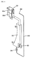
- FIG. 7 is a view showing that the slide member 210a of the fragrance injection unit 210 has been inserted into the fixed member 210b
- FIG. 8 is a view showing that the slide member 210a of the fragrance injection unit 210 has been drawn out of the fixed member 210bby a sliding motion.
- the slide member 210a is in an inserted state into the fixed member 210b, and the fixed member 210b is in an inserted state into the front supporter 28 as shown in FIG. 7 .
- the fragrant liquid inside the fragrance storage unit 220 is sprayed into the drum 15.
- the slide member 210a of the fragrance injection unit 210 is drawn out of the fixed member 210. Accordingly, the fragrant liquid is injected into the slide member 210a for supplement.
- the fragrance supplying module may comprise a cartridge detachably mounted to the front supporter 28 and containing fragrance therein; a pump connected to the cartridge; and a nozzle connected to the pump by a tube, for spraying fragrance into the drum. That is, instead of the fragrance injection unit 210 and the fragrance storage unit 220 of the first embodiment, a cartridge having fragrance filled therein is used in the second embodiment. In the case that fragrance filled in one cartridge is used up, the cartridge is replaced by a new cartridge. Accordingly, there is no need to inject fragrant liquid into the slide member 210a, again. Also, the cartridge may be detached from the clothes dryer to be supplemented with fragrant liquid. Then, the cartridge may be mounted to the front supporter 28, again. To this end, a cartridge accommodation unit for accommodating the cartridge therein may be formed at the front supporter 28.
- a user opens the door 24 to put laundry into the drum 15, and then inputs a drying course with fragrance spray through an input unit mounted on the control panel 14.
- the driving motor 20 is operated.
- the belt 16 wound on an outer circumferential surface of the drum 15 and the motor shaft 21 is rotated as the motor shaft 21 is rotated. Accordingly, the drum 15 is also rotated.
- the cooling fan 22 and the drying fan 19 connected to the driving motor 20 are also driven, and the heater 18 mounted in the drying duct 17 heats air introduced into the drum 15.
- the steam generator 100 heats water therein by using the heater 18, thereby supplying steam into the drum 15.
- a process for spraying fragrance into the drum 15 may be separately performed from the process for spraying steam into the drum 15.
- a fragrant liquid injected into the fragrance injection unit 210 is stored in the fragrance storage unit 220. Then, the fragrant liquid is compressed by the pump 230 when necessary, thereby being sprayed into the drum 15 through the nozzle 250 in the form of mists.
- the time to spray the fragrant liquid may be manually controlled by a user's manipulation of the control panel, or may be automatically controlled by a microprocessor. In the case of the latter automatic control, a user selects his or her desired drying course among a plurality of pre-programmed drying courses on the control panel. According to the selected drying course, the time to spray the fragrant liquid is automatically controlled by a microprocessor.
- the level sensor implemented as an electrode sensor or a magnetic sensor for measuring the amount of the fragrant liquid inside the fragrance storage unit 220 detects the insufficient state of the fragrant liquid.
- the microprocessor may generate a signal informing the insufficient state of the fragrant liquid to a user.
- the user opens the door to pull the slide member 210a of the fragrance injection unit 210 installed at the front supporter 28. Accordingly, the slide member 210a is drawn out of the fixed member 210b.
- the user injects fragrant liquid into the slide member 210a.
- the cartridge having completely-used fragrance is separated from the clothes dryer. Then, the cartridge is supplemented with fragrant liquid, and is mounted to the front supporter 28, again. Alternatively, the cartridge may be replace by a new one.
Landscapes
- Engineering & Computer Science (AREA)
- Textile Engineering (AREA)
- Detail Structures Of Washing Machines And Dryers (AREA)
Description
- The present invention relates to a clothes dryer, and particularly, to a clothes dryer having a fragrance supplying module capable of spraying fragrance into a drum thereof.
- In general, a clothes dryer indicates an apparatus for drying laundry having completely undergone a dehydration process after a washing process, by introducing the laundry into a drum of the clothes dryer, and by evaporating moisture inside the laundry by supplying hot blast into the drum.
- The clothes dryer comprises a drum disposed in the clothes dryer and into which laundry is introduced, a driving motor for driving the drum, a blow fan for blowing air into the drum, and a heating means for heating the air introduced into the drum.
- The heating means may use high-temperature electric resistance heat generated by using an electric resistance, or combustion heat generated by combusting gas.
- Air having been discharged from the drum contains moisture of the laundry inside the drum, thereby changing into high-temperature humid air. According to a method for processing the high-temperature humid air, the clothes drier may be classified. More concretely, the clothes drier is classified into a condensation type clothes dryer for condensing moisture inside high-temperature humid air by heat-exchanging the high-temperature humid air with external air through circulation in the clothes dryer without discharging the high-temperature humid air out of the clothes dryer, and an exhaustion type clothes dryer for directly discharging high-temperature humid air having passed through the drum to the outside.
- When drawing the laundry having completely undergone a drying process out of the clothes drier, it was required to supply a fresh feeling of the laundry to a user, and to remove wrinkles of the laundry. Accordingly, there have been needs to supply a fragrant material into the drum of the clothes drier during a drying process. Also, required is a means for easily supplementing the fragrant material supplied into the drum when the fragrant material is used up. Especially, required is a means for easily spraying a liquid fragrant material into the drum.
-
EP 2 055 824 A1 describes a dryer. Herein, the dryer includes a cabinet, a drum in which a drying object is held, a steam generation device to supply steam to the drum, a water supply device to supply water to the steam generation device in order to generate steam, an additive holding part in which an additive is held, and an additive supply device to supply the additive held in the additive holding part to the drum. - Therefore, an object of the present invention is to provide a means capable of easily spraying a fragrant liquid into a drum of a clothes drier during a drying process, so as to supply fresh fragrance to laundry having been completely dried.
- Another object of the present invention is to provide a fragrance supplying module capable of re-supplying a fragrant liquid to laundry when necessary, by being installed at a position to which a user can easily approach.
- To achieve these and other advantages and in accordance with the purpose of the present invention, as embodied and broadly described herein, there is provided a clothes dryer having a fragrance supplying module, comprising: a body that forms appearance of the clothes dryer; a drum rotatably installed in the body; a front supporter for supporting the drum at a front side; and a rear supporter for supporting the drum at a rear side, wherein the fragrance supplying module for supplying fragrance into the drum is provided at the front supporter.
- As the fragrance supplying module is provided at the front supporter, a fragrant liquid can be easily replaced by a new one or supplemented since a user's approach to the fragrance supplying module is facilitated.
- The clothes dryer may further comprise a steam generator for supplying steam to the drum. Accordingly, the clothes dryer may supply both steam and fragrance to laundry.
- The fragrance supply module may comprise a fragrance injection unit; a fragrance storage unit connected to the fragrance injection unit; a pump connected to the fragrance storage unit; and a nozzle connected to the pump by a tube, for spraying fragrance into the drum.
- The fragrance injection unit may comprise a fixed member insertion-fixed to the front supporter, and a slide member slidably mounted to the fixed member.
- Protrusions may be formed on both side surfaces of the slide member, and guide members for guiding the protrusions inserted thereto to slide may be formed at the fixed member.
- A discharge opening may be formed at a lower part of the fixed member, and may be connected to the fragrance storage unit by a pipe. Accordingly, a fragrant liquid supplied from the fragrance injection unit is introduced into the fragrance storage unit through the pipe.
- In the fragrance storage unit, may be disposed a level sensor for measuring an amount of a stored fragrant liquid. When the fragrant liquid is not sufficient, a user may be informed the state through the level sensor, thus to supplement the fragrant liquid.
- Preferably, the fragrance injection unit may be installed at a side surface of the front supporter. And, an exit of the nozzle may be preferably installed at an upper part of the front supporter so as to be toward the inside of the drum.
- The fragrance supplying module may comprise a cartridge detachably mounted to the
front supporter 28 and containing fragrance therein; a pump connected to the cartridge; and a nozzle connected to the pump by a tube, for spraying fragrance into the drum. In the case that fragrance contained in the cartridge is used up, only the cartridge may be replace by a new one. To this end, a cartridge accommodation unit for accommodating the cartridge therein may be formed at the front supporter. - The clothes dryer according to the present invention is provided with a means for easily spraying a fragrant liquid into the drum disposed in the clothes dryer during a drying process. And, the fragrant liquid can be easily supplied to the fragrance supplying module. Since the fragrance supplying module is installed at a position to which a user can easily approach, it can be easily replaced by a new one, or can be easily repaired when necessary.
- The foregoing and other objects, features, aspects and advantages of the present invention will become more apparent from the following detailed description of the present invention when taken in conjunction with the accompanying drawings.
- The accompanying drawings, which are included to provide a further understanding of the invention and are incorporated in and constitute a part of this specification, illustrate embodiments of the invention and together with the description serve to explain the principles of the invention.
- In the drawings:
-
FIG. 1 is a perspective view of a clothes dryer according to the present invention; -
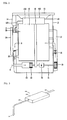
FIG. 2 is a side sectional view of the clothes dryer ofFIG. 1 ; -
FIG. 3 is a perspective view of a steam generator of the clothes dryer; -
FIG. 4 shows a mounting position of a fragrance supplying module at a front supporter, which is viewed from the front side of the clothes dryer; -
FIG. 5 shows the fragrance supplying module mounted at the front supporter, which is viewed from the inside of the clothes dryer; -
FIG. 6 is a perspective view of the fragrance supplying module; -
FIG. 7 is a view showing that a slide member of a fragrance injection unit of the fragrance supplying module has been inserted into a fixed member; and -
FIG. 8 is a view showing that the slide member of the fragrance injection unit of the fragrance supplying module has been drawn out of the fixed member by a sliding motion. - Description will now be given in detail of the present invention, with reference to the accompanying drawings.
- Hereinafter, a clothes dryer having a fragrance supplying module according to the present invention will be explained in more detail.
- Referring to
FIGS. 1 and2 , theclothes dryer 10 having a fragrance supplying module according to the present invention comprises afront cover 11 that forms appearance thereof, arear cover 12, atop cover 13, and adrum 15 into which laundry is introduced. Afront supporter 28 of theclothes dryer 10 is mounted at a rear side of thefront cover 11, and supports a front opening of thedrum 15. - A
door 24 for opening and closing the front opening of thedrum 15 is provided at thefront cover 11. And, acontrol panel 14 having each kind of buttons for inputting drying conditions is provided at an upper part of thefront cover 11. - Also, the
clothes dryer 10 comprises adrying fan 19 for making air inside thedrum 15 circulate therein, adrying duct 17 for guiding circulation air having passed through thedrying drum 15 to be introduced into thedrum 15, aheater 18 disposed in thedrying duct 17 for heating air introduced into thedrum 15, and asteam generator 100 disposed at an outer side of thedrum 15 for generating steam. - Below the
drum 15, further comprised are abase 23 having a flow path of circulation air (A) and a flow path of external air (B) which performs heat exchange with the circulation air; a drivingmotor 20 mounted on an upper part of thebase 23 for driving thedrum 15; abelt 16 for transmitting a rotation force generated by the drivingmotor 20 to thedrum 15; acooling fan 22 connected to amotor shaft 21 of thedriving motor 20 for sucking indoor air; and acondenser 26 mounted at an inner side of thebase 23, for heat-exchanging the external air (B) with the circulation air (A). -
FIG. 3 is a perspective view of a steam generator of the clothes dryer. - Referring to
FIG. 3 , thesteam generator 100 includes awater supplying hose 110 for supplying water having a room temperature to asteam generator body 150, thesteam generator body 150 for storing water supplied thereto, a heater (not shown) disposed in thesteam generator body 150 for heating the stored water, adischarge hose 120 for discharging steam generated from thesteam generator body 150, and asteam nozzle 121 connected to the end of thedischarge hose 120. Under these configurations, water having been supplied to thesteam generator body 150 through thewater supplying hose 110 is heated by the heater, and then is discharged to thedischarge hose 120. And, the discharged steam is sprayed into thedrum 15 through thesteam nozzle 121. -
FIG. 4 shows a mounting position of a fragrance supplying module at a front supporter, which is viewed from the front side of the clothes dryer. - Referring to
FIG. 4 , thefragrance supplying module 200 is installed at a right part of thefront supporter 28. InFIG. 4 , the position of thefront supporter 28 where thefragrance supplying module 200 is installed is merely exemplary. Thefragrance supplying module 200 may be installed at a lower part or a left part (FIG. 5 ) of thefront supporter 28. -
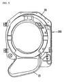
FIG. 5 shows thefragrance supplying module 200 for supplying fragrance into thedrum 15. And, FIG. 15 shows the shape of thefront supporter 28 that supports the front opening of thedrum 15, which is viewed from the inside of the clothes dryer. Afilter 25 is mounted below the front opening of thedrum 15, thereby filtering lint included in air discharged from the drum. Thefragrance supplying module 200 is mounted at a side surface (left side inFIG. 5 ) of thefront supporter 28. -
FIG. 6 is a disassembled perspective view of the fragrance supplying module ofFIG. 5 . - Referring to
FIG. 6 , thefragrance supply module 200 includes afragrance injection unit 210, afragrance storage unit 220 connected to thefragrance injection unit 210; apump 230 connected to thefragrance storage unit 220; and anozzle 250 connected to thepump 230 by a tube, for spraying fragrance into thedrum 15. - The
fragrance injection unit 210 is composed of aslide member 210a and a fixedmember 210b. The fixedmember 210b is fixedly mounted to thefront supporter 28, and theslide member 210a is slidably mounted to the fixedmember 210b. Protrusions 210aa are formed on both side surfaces of theslide member 210a, and guide members 210bb for guiding the protrusions 210aa inserted thereto to perform a sliding motion. Accordingly, theslide member 210a may be inserted into the fixedmember 210b by a sliding motion, thereby being inserted into thefront supporter 28. - A discharge opening is formed at a lower part of the fixed
member 210b, and is connected to thefragrance storage unit 220. Under this configuration, when a user is to inject a fragrant liquid into thefragrance storage unit 220, theslide member 210a of thefragrance injection unit 210 is pulled to be protruding from thefront supporter 28. Then, the fragrant liquid is injected into theslide member 210a for supplement. - In the
fragrance storage unit 220, may be disposed alevel sensor 221 for measuring the amount of a fragrant liquid stored in thefragrance storage unit 220. Thelevel sensor 221 may be an electrode sensor, or a reed switch operated by a magnetic field generated from a permanent magnet and a current-carrying coil. The present invention may be also provided with a means for informing a user that the amount of fragrance inside thefragrance storage unit 220 is not sufficient. Preferably, the means is installed at a control panel disposed on a front surface of the clothes dryer. -
FIG. 7 is a view showing that theslide member 210a of thefragrance injection unit 210 has been inserted into the fixedmember 210b, andFIG. 8 is a view showing that theslide member 210a of thefragrance injection unit 210 has been drawn out of the fixed member 210bby a sliding motion. - In the case of requiring no additional fragrant liquid while the clothes dryer performs a drying process, the
slide member 210a is in an inserted state into the fixedmember 210b, and the fixedmember 210b is in an inserted state into thefront supporter 28 as shown inFIG. 7 . And, the fragrant liquid inside thefragrance storage unit 220 is sprayed into thedrum 15. - However, in the case of requiring an additional fragrant liquid for supplement after the clothes dryer has performed drying processes a plurality of times, the
slide member 210a of thefragrance injection unit 210 is drawn out of the fixedmember 210. Accordingly, the fragrant liquid is injected into theslide member 210a for supplement. - According to a second embodiment of the present invention, the fragrance supplying module may comprise a cartridge detachably mounted to the
front supporter 28 and containing fragrance therein; a pump connected to the cartridge; and a nozzle connected to the pump by a tube, for spraying fragrance into the drum. That is, instead of thefragrance injection unit 210 and thefragrance storage unit 220 of the first embodiment, a cartridge having fragrance filled therein is used in the second embodiment. In the case that fragrance filled in one cartridge is used up, the cartridge is replaced by a new cartridge. Accordingly, there is no need to inject fragrant liquid into theslide member 210a, again. Also, the cartridge may be detached from the clothes dryer to be supplemented with fragrant liquid. Then, the cartridge may be mounted to thefront supporter 28, again. To this end, a cartridge accommodation unit for accommodating the cartridge therein may be formed at thefront supporter 28. - Hereinafter, will be briefly explained a process for performing a drying process with spraying fragrance to the
drum 15 inside theclothes dryer 10. - Firstly, a user opens the
door 24 to put laundry into thedrum 15, and then inputs a drying course with fragrance spray through an input unit mounted on thecontrol panel 14. Once the drying process starts, the drivingmotor 20 is operated. And, thebelt 16 wound on an outer circumferential surface of thedrum 15 and themotor shaft 21 is rotated as themotor shaft 21 is rotated. Accordingly, thedrum 15 is also rotated. Here, the coolingfan 22 and the dryingfan 19 connected to the drivingmotor 20 are also driven, and theheater 18 mounted in the dryingduct 17 heats air introduced into thedrum 15. - In the case of requiring steam supply during the drying process, the
steam generator 100 heats water therein by using theheater 18, thereby supplying steam into thedrum 15. In the drying process of the present invention, a process for spraying fragrance into thedrum 15 may be separately performed from the process for spraying steam into thedrum 15. - In the present invention, a fragrant liquid injected into the
fragrance injection unit 210 is stored in thefragrance storage unit 220. Then, the fragrant liquid is compressed by thepump 230 when necessary, thereby being sprayed into thedrum 15 through thenozzle 250 in the form of mists. The time to spray the fragrant liquid may be manually controlled by a user's manipulation of the control panel, or may be automatically controlled by a microprocessor. In the case of the latter automatic control, a user selects his or her desired drying course among a plurality of pre-programmed drying courses on the control panel. According to the selected drying course, the time to spray the fragrant liquid is automatically controlled by a microprocessor. - Once the fragrant liquid stored in the
fragrance storage unit 220 of thefragrance supplying module 200 is used up after the clothes dryer has performed drying processes a plurality of times, the level sensor implemented as an electrode sensor or a magnetic sensor for measuring the amount of the fragrant liquid inside thefragrance storage unit 220 detects the insufficient state of the fragrant liquid. As the level sensor transmits the information to the microprocessor, the microprocessor may generate a signal informing the insufficient state of the fragrant liquid to a user. In order to inject fragrant liquid into thefragrance supplying module 200 for supplement, the user opens the door to pull theslide member 210a of thefragrance injection unit 210 installed at thefront supporter 28. Accordingly, theslide member 210a is drawn out of the fixedmember 210b. Under this state, the user injects fragrant liquid into theslide member 210a. In the case of using a cartridge having fragrance filled therein instead of the fragrance injection unit and the fragrance storage unit, the cartridge having completely-used fragrance is separated from the clothes dryer. Then, the cartridge is supplemented with fragrant liquid, and is mounted to thefront supporter 28, again. Alternatively, the cartridge may be replace by a new one. - The foregoing embodiments and advantages are merely exemplary and are not to be construed as limiting the present disclosure. The present teachings can be readily applied to other types of apparatuses. This description is intended to be illustrative, and not to limit the scope of the claims. Many alternatives, modifications, and variations will be apparent to those skilled in the art. The features, structures, methods, and other characteristics of the exemplary embodiments described herein may be combined in various ways to obtain additional and/or alternative exemplary embodiments.
Claims (9)
- A clothes dryer having a fragrance supplying module comprising:- a body that forms appearance of the clothes dryer,- a front cover (11) that forms appearance thereof,- a rear cover (12),- a top cover (13),- a drum (15) rotatably installed in the body and into which laundry is introduced,- a front supporter (28) of the clothes dryer (10) mounted at a rear side of the front cover (11) for supporting the drum at a front side and supporting a front opening of the drum (15);characterized in that the fragrance supplying module (200) is provided at the front supporter (28) for supplying fragrance into the drum (15).
- The clothes dryer of claim 1, wherein the fragrance supplying module (200) comprises:- a fragrance storage unit (220) for storing fragrant liquid; and- a fragrance injection unit (210) for injecting fragrant liquid.
- The clothes dryer of claim 2, wherein the fragrance supplying module (200) further comprises:- a pump (230) connected to the fragrance storage unit (220); and- a nozzle (250) connected to the pump (230) by a tube, for spraying fragrance into the drum (15).
- The clothes dryer of claim 3, wherein the fragrance injection unit (210) comprises:- a fixed member (210b) insertion-fixed to the front supporter (28); and- a slide member (210a) slidably mounted to the fixed member (210b).
- The clothes dryer of claim 4, wherein protrusions (210aa) are formed on both side surfaces of the slide member (210a), and guide members (210bb) for guiding the protrusions inserted thereto to slide are formed at the fixed member (210b).
- The clothes dryer of claim 4, wherein a discharge opening is formed at a lower part of the fixed member (210b), and is connected to the fragrance storage unit (220).
- The clothes dryer of claim 3, wherein the fragrance storage unit (220) is provided with, therein, a level sensor (221) for measuring an amount of a fragrant liquid stored in the fragrance storage unit (220).
- The clothes dryer of claim 3, wherein the fragrance injection unit (210) is installed at a side surface of the front supporter (28).
- The clothes dryer of claim 3, wherein an exit of the nozzle (250) is installed at an upper side of the front supporter (28) so as to be toward inside of the drum (15).
Applications Claiming Priority (1)
| Application Number | Priority Date | Filing Date | Title |
|---|---|---|---|
| KR1020080069727A KR101028275B1 (en) | 2008-07-17 | 2008-07-17 | Clothes dryer having odor supplying module |
Publications (2)
| Publication Number | Publication Date |
|---|---|
| EP2145995A1 EP2145995A1 (en) | 2010-01-20 |
| EP2145995B1 true EP2145995B1 (en) | 2015-12-23 |
Family
ID=41217630
Family Applications (1)
| Application Number | Title | Priority Date | Filing Date |
|---|---|---|---|
| EP09009282.6A Not-in-force EP2145995B1 (en) | 2008-07-17 | 2009-07-16 | Clothes dryer having fragrance supplying module |
Country Status (8)
| Country | Link |
|---|---|
| US (1) | US20100011607A1 (en) |
| EP (1) | EP2145995B1 (en) |
| KR (1) | KR101028275B1 (en) |
| CN (1) | CN101629378B (en) |
| AU (1) | AU2009202846B2 (en) |
| BR (1) | BRPI0902731B1 (en) |
| RU (1) | RU2410480C1 (en) |
| TW (1) | TWI392784B (en) |
Families Citing this family (10)
| Publication number | Priority date | Publication date | Assignee | Title |
|---|---|---|---|---|
| KR100556503B1 (en) * | 2002-11-26 | 2006-03-03 | 엘지전자 주식회사 | Control Method of Drying Time for Dryer |
| DE10360867A1 (en) * | 2003-12-23 | 2005-07-21 | BSH Bosch und Siemens Hausgeräte GmbH | Method and apparatus for drying laundry |
| DE102005013051A1 (en) * | 2005-03-18 | 2006-09-21 | BSH Bosch und Siemens Hausgeräte GmbH | Condensation Dryer |
| DE102005013053A1 (en) * | 2005-05-23 | 2006-11-30 | BSH Bosch und Siemens Hausgeräte GmbH | Condensation Dryer |
| KR101072107B1 (en) * | 2008-09-26 | 2011-10-10 | 엘지전자 주식회사 | Clothes dryer having fragrance supplying module |
| KR101174660B1 (en) | 2009-02-17 | 2012-08-21 | 엘지전자 주식회사 | Method for fragrance spraying of clothes handling apparatus having fragrance supplying module |
| US8844156B2 (en) | 2010-12-14 | 2014-09-30 | Whirlpool Corporation | Laundry treating appliance with purged chemistry conduits |
| CN106758014B (en) * | 2016-12-29 | 2023-05-16 | 珠海格力电器股份有限公司 | Washing machine and method for operating the same |
| CN110093762A (en) * | 2018-01-31 | 2019-08-06 | 青岛海尔滚筒洗衣机有限公司 | The drying unit and application method of a kind of dryer and the dryer with it |
| US10889934B2 (en) | 2019-04-01 | 2021-01-12 | Haier Us Appliance Solutions, Inc. | Removable additive container for laundry appliances |
Family Cites Families (12)
| Publication number | Priority date | Publication date | Assignee | Title |
|---|---|---|---|---|
| US3180037A (en) * | 1962-05-07 | 1965-04-27 | Whirlpool Co | Apparatus for bleaching fabrics and the like |
| DE2823351A1 (en) * | 1978-05-29 | 1979-12-13 | Henkel Kgaa | PROCESS FOR CONDITIONING AND DRYING LAUNDRY AND DEVICE FOR CARRYING OUT THE PROCESS |
| US20070151312A1 (en) * | 2005-12-30 | 2007-07-05 | Bruce Beihoff C | Modular fabric revitalizing system |
| DE10260156A1 (en) * | 2002-12-20 | 2004-07-01 | BSH Bosch und Siemens Hausgeräte GmbH | Tumble dryer and use of an ultrasonic atomizer |
| KR20050037186A (en) * | 2003-10-17 | 2005-04-21 | 엘지전자 주식회사 | Clothes dryer |
| US7600402B2 (en) * | 2003-11-04 | 2009-10-13 | Lg Electronics Inc. | Washing apparatus and control method thereof |
| KR20050118895A (en) * | 2004-06-15 | 2005-12-20 | 삼성전자주식회사 | Washing machine having a detergent feeding device |
| US20070151311A1 (en) * | 2005-12-30 | 2007-07-05 | Mcallister Karl D | Fabric revitalizing system |
| ES2371505T3 (en) * | 2006-05-02 | 2012-01-03 | Electrolux Home Products Corporation N.V. | DRYER WITH DRY SEQUENCE IN WHICH AN ADDITIVE IS USED. |
| KR20080027677A (en) * | 2006-09-25 | 2008-03-28 | 엘지전자 주식회사 | Washing machine |
| EP2055824B1 (en) | 2007-11-02 | 2014-07-30 | LG Electronics Inc. | Dryer |
| US20090272004A1 (en) * | 2008-05-01 | 2009-11-05 | Whirlpool Corporation | Intelligent dispensing in a laundry appliance |
-
2008
- 2008-07-17 KR KR1020080069727A patent/KR101028275B1/en active IP Right Grant
-
2009
- 2009-07-14 AU AU2009202846A patent/AU2009202846B2/en not_active Ceased
- 2009-07-16 US US12/458,596 patent/US20100011607A1/en not_active Abandoned
- 2009-07-16 RU RU2009127401/12A patent/RU2410480C1/en active
- 2009-07-16 BR BRPI0902731-9A patent/BRPI0902731B1/en not_active IP Right Cessation
- 2009-07-16 EP EP09009282.6A patent/EP2145995B1/en not_active Not-in-force
- 2009-07-17 CN CN2009101399696A patent/CN101629378B/en not_active Expired - Fee Related
- 2009-07-17 TW TW098124344A patent/TWI392784B/en not_active IP Right Cessation
Also Published As
| Publication number | Publication date |
|---|---|
| CN101629378A (en) | 2010-01-20 |
| KR20100009044A (en) | 2010-01-27 |
| BRPI0902731A2 (en) | 2010-05-25 |
| EP2145995A1 (en) | 2010-01-20 |
| KR101028275B1 (en) | 2011-04-11 |
| AU2009202846B2 (en) | 2010-12-23 |
| RU2410480C1 (en) | 2011-01-27 |
| CN101629378B (en) | 2011-12-14 |
| TWI392784B (en) | 2013-04-11 |
| US20100011607A1 (en) | 2010-01-21 |
| BRPI0902731B1 (en) | 2019-06-18 |
| AU2009202846A1 (en) | 2010-02-04 |
| TW201005150A (en) | 2010-02-01 |
Similar Documents
| Publication | Publication Date | Title |
|---|---|---|
| EP2145995B1 (en) | Clothes dryer having fragrance supplying module | |
| EP2145997B1 (en) | Clothes dryer having fragrance supplying module | |
| EP2145998B1 (en) | Method for controlling fragrance spray for clothes dryer | |
| EP1936021B1 (en) | Method for controlling laundry machine | |
| EP2145996B1 (en) | Clothes dryer | |
| TWI379025B (en) | ||
| CN102365401B (en) | Operating method for laundry equipment including a scent supply module | |
| US9708751B2 (en) | Clothes dryer provided with scent-supply module in a top plate | |
| KR20100093940A (en) | Method for fragrance spraying of clothes handling apparatus having fragrance supplying module | |
| KR20110078379A (en) | Method for controlling dryer | |
| KR101072029B1 (en) | Clothes dryer having fragrance supplying module | |
| KR20100115214A (en) | Method for operating of clothes treatment apparatus having fragrance supplying module | |
| KR20090041542A (en) | Laundry machine and controlling method of the same |
Legal Events
| Date | Code | Title | Description |
|---|---|---|---|
| PUAI | Public reference made under article 153(3) epc to a published international application that has entered the european phase |
Free format text: ORIGINAL CODE: 0009012 |
|
| AK | Designated contracting states |
Kind code of ref document: A1 Designated state(s): AT BE BG CH CY CZ DE DK EE ES FI FR GB GR HR HU IE IS IT LI LT LU LV MC MK MT NL NO PL PT RO SE SI SK SM TR |
|
| AX | Request for extension of the european patent |
Extension state: AL BA RS |
|
| 17P | Request for examination filed |
Effective date: 20100430 |
|
| GRAP | Despatch of communication of intention to grant a patent |
Free format text: ORIGINAL CODE: EPIDOSNIGR1 |
|
| INTG | Intention to grant announced |
Effective date: 20150716 |
|
| GRAS | Grant fee paid |
Free format text: ORIGINAL CODE: EPIDOSNIGR3 |
|
| RAP1 | Party data changed (applicant data changed or rights of an application transferred) |
Owner name: LG ELECTRONICS INC. |
|
| GRAA | (expected) grant |
Free format text: ORIGINAL CODE: 0009210 |
|
| AK | Designated contracting states |
Kind code of ref document: B1 Designated state(s): AT BE BG CH CY CZ DE DK EE ES FI FR GB GR HR HU IE IS IT LI LT LU LV MC MK MT NL NO PL PT RO SE SI SK SM TR |
|
| REG | Reference to a national code |
Ref country code: GB Ref legal event code: FG4D |
|
| REG | Reference to a national code |
Ref country code: CH Ref legal event code: EP |
|
| REG | Reference to a national code |
Ref country code: IE Ref legal event code: FG4D |
|
| REG | Reference to a national code |
Ref country code: AT Ref legal event code: REF Ref document number: 766618 Country of ref document: AT Kind code of ref document: T Effective date: 20160115 |
|
| REG | Reference to a national code |
Ref country code: DE Ref legal event code: R096 Ref document number: 602009035334 Country of ref document: DE |
|
| REG | Reference to a national code |
Ref country code: LT Ref legal event code: MG4D |
|
| REG | Reference to a national code |
Ref country code: NL Ref legal event code: MP Effective date: 20151223 |
|
| PG25 | Lapsed in a contracting state [announced via postgrant information from national office to epo] |
Ref country code: LT Free format text: LAPSE BECAUSE OF FAILURE TO SUBMIT A TRANSLATION OF THE DESCRIPTION OR TO PAY THE FEE WITHIN THE PRESCRIBED TIME-LIMIT Effective date: 20151223 Ref country code: NO Free format text: LAPSE BECAUSE OF FAILURE TO SUBMIT A TRANSLATION OF THE DESCRIPTION OR TO PAY THE FEE WITHIN THE PRESCRIBED TIME-LIMIT Effective date: 20160323 Ref country code: HR Free format text: LAPSE BECAUSE OF FAILURE TO SUBMIT A TRANSLATION OF THE DESCRIPTION OR TO PAY THE FEE WITHIN THE PRESCRIBED TIME-LIMIT Effective date: 20151223 |
|
| REG | Reference to a national code |
Ref country code: AT Ref legal event code: MK05 Ref document number: 766618 Country of ref document: AT Kind code of ref document: T Effective date: 20151223 |
|
| PG25 | Lapsed in a contracting state [announced via postgrant information from national office to epo] |
Ref country code: NL Free format text: LAPSE BECAUSE OF FAILURE TO SUBMIT A TRANSLATION OF THE DESCRIPTION OR TO PAY THE FEE WITHIN THE PRESCRIBED TIME-LIMIT Effective date: 20151223 Ref country code: GR Free format text: LAPSE BECAUSE OF FAILURE TO SUBMIT A TRANSLATION OF THE DESCRIPTION OR TO PAY THE FEE WITHIN THE PRESCRIBED TIME-LIMIT Effective date: 20160324 Ref country code: SE Free format text: LAPSE BECAUSE OF FAILURE TO SUBMIT A TRANSLATION OF THE DESCRIPTION OR TO PAY THE FEE WITHIN THE PRESCRIBED TIME-LIMIT Effective date: 20151223 Ref country code: FI Free format text: LAPSE BECAUSE OF FAILURE TO SUBMIT A TRANSLATION OF THE DESCRIPTION OR TO PAY THE FEE WITHIN THE PRESCRIBED TIME-LIMIT Effective date: 20151223 Ref country code: LV Free format text: LAPSE BECAUSE OF FAILURE TO SUBMIT A TRANSLATION OF THE DESCRIPTION OR TO PAY THE FEE WITHIN THE PRESCRIBED TIME-LIMIT Effective date: 20151223 |
|
| REG | Reference to a national code |
Ref country code: FR Ref legal event code: PLFP Year of fee payment: 8 |
|
| PG25 | Lapsed in a contracting state [announced via postgrant information from national office to epo] |
Ref country code: CZ Free format text: LAPSE BECAUSE OF FAILURE TO SUBMIT A TRANSLATION OF THE DESCRIPTION OR TO PAY THE FEE WITHIN THE PRESCRIBED TIME-LIMIT Effective date: 20151223 Ref country code: ES Free format text: LAPSE BECAUSE OF FAILURE TO SUBMIT A TRANSLATION OF THE DESCRIPTION OR TO PAY THE FEE WITHIN THE PRESCRIBED TIME-LIMIT Effective date: 20151223 |
|
| PG25 | Lapsed in a contracting state [announced via postgrant information from national office to epo] |
Ref country code: PT Free format text: LAPSE BECAUSE OF FAILURE TO SUBMIT A TRANSLATION OF THE DESCRIPTION OR TO PAY THE FEE WITHIN THE PRESCRIBED TIME-LIMIT Effective date: 20160426 Ref country code: IS Free format text: LAPSE BECAUSE OF FAILURE TO SUBMIT A TRANSLATION OF THE DESCRIPTION OR TO PAY THE FEE WITHIN THE PRESCRIBED TIME-LIMIT Effective date: 20160423 Ref country code: AT Free format text: LAPSE BECAUSE OF FAILURE TO SUBMIT A TRANSLATION OF THE DESCRIPTION OR TO PAY THE FEE WITHIN THE PRESCRIBED TIME-LIMIT Effective date: 20151223 Ref country code: EE Free format text: LAPSE BECAUSE OF FAILURE TO SUBMIT A TRANSLATION OF THE DESCRIPTION OR TO PAY THE FEE WITHIN THE PRESCRIBED TIME-LIMIT Effective date: 20151223 Ref country code: RO Free format text: LAPSE BECAUSE OF FAILURE TO SUBMIT A TRANSLATION OF THE DESCRIPTION OR TO PAY THE FEE WITHIN THE PRESCRIBED TIME-LIMIT Effective date: 20151223 Ref country code: SK Free format text: LAPSE BECAUSE OF FAILURE TO SUBMIT A TRANSLATION OF THE DESCRIPTION OR TO PAY THE FEE WITHIN THE PRESCRIBED TIME-LIMIT Effective date: 20151223 Ref country code: PL Free format text: LAPSE BECAUSE OF FAILURE TO SUBMIT A TRANSLATION OF THE DESCRIPTION OR TO PAY THE FEE WITHIN THE PRESCRIBED TIME-LIMIT Effective date: 20151223 Ref country code: SM Free format text: LAPSE BECAUSE OF FAILURE TO SUBMIT A TRANSLATION OF THE DESCRIPTION OR TO PAY THE FEE WITHIN THE PRESCRIBED TIME-LIMIT Effective date: 20151223 |
|
| REG | Reference to a national code |
Ref country code: DE Ref legal event code: R097 Ref document number: 602009035334 Country of ref document: DE |
|
| PLBE | No opposition filed within time limit |
Free format text: ORIGINAL CODE: 0009261 |
|
| STAA | Information on the status of an ep patent application or granted ep patent |
Free format text: STATUS: NO OPPOSITION FILED WITHIN TIME LIMIT |
|
| PG25 | Lapsed in a contracting state [announced via postgrant information from national office to epo] |
Ref country code: DK Free format text: LAPSE BECAUSE OF FAILURE TO SUBMIT A TRANSLATION OF THE DESCRIPTION OR TO PAY THE FEE WITHIN THE PRESCRIBED TIME-LIMIT Effective date: 20151223 |
|
| 26N | No opposition filed |
Effective date: 20160926 |
|
| PG25 | Lapsed in a contracting state [announced via postgrant information from national office to epo] |
Ref country code: BE Free format text: LAPSE BECAUSE OF FAILURE TO SUBMIT A TRANSLATION OF THE DESCRIPTION OR TO PAY THE FEE WITHIN THE PRESCRIBED TIME-LIMIT Effective date: 20151223 |
|
| PG25 | Lapsed in a contracting state [announced via postgrant information from national office to epo] |
Ref country code: SI Free format text: LAPSE BECAUSE OF FAILURE TO SUBMIT A TRANSLATION OF THE DESCRIPTION OR TO PAY THE FEE WITHIN THE PRESCRIBED TIME-LIMIT Effective date: 20151223 |
|
| REG | Reference to a national code |
Ref country code: CH Ref legal event code: PL |
|
| PG25 | Lapsed in a contracting state [announced via postgrant information from national office to epo] |
Ref country code: MC Free format text: LAPSE BECAUSE OF FAILURE TO SUBMIT A TRANSLATION OF THE DESCRIPTION OR TO PAY THE FEE WITHIN THE PRESCRIBED TIME-LIMIT Effective date: 20151223 |
|
| PG25 | Lapsed in a contracting state [announced via postgrant information from national office to epo] |
Ref country code: CH Free format text: LAPSE BECAUSE OF NON-PAYMENT OF DUE FEES Effective date: 20160731 Ref country code: LI Free format text: LAPSE BECAUSE OF NON-PAYMENT OF DUE FEES Effective date: 20160731 |
|
| REG | Reference to a national code |
Ref country code: IE Ref legal event code: MM4A |
|
| REG | Reference to a national code |
Ref country code: FR Ref legal event code: PLFP Year of fee payment: 9 |
|
| PG25 | Lapsed in a contracting state [announced via postgrant information from national office to epo] |
Ref country code: IE Free format text: LAPSE BECAUSE OF NON-PAYMENT OF DUE FEES Effective date: 20160716 |
|
| PGFP | Annual fee paid to national office [announced via postgrant information from national office to epo] |
Ref country code: GB Payment date: 20170608 Year of fee payment: 9 |
|
| PG25 | Lapsed in a contracting state [announced via postgrant information from national office to epo] |
Ref country code: LU Free format text: LAPSE BECAUSE OF NON-PAYMENT OF DUE FEES Effective date: 20160716 |
|
| PG25 | Lapsed in a contracting state [announced via postgrant information from national office to epo] |
Ref country code: HU Free format text: LAPSE BECAUSE OF FAILURE TO SUBMIT A TRANSLATION OF THE DESCRIPTION OR TO PAY THE FEE WITHIN THE PRESCRIBED TIME-LIMIT; INVALID AB INITIO Effective date: 20090716 Ref country code: CY Free format text: LAPSE BECAUSE OF FAILURE TO SUBMIT A TRANSLATION OF THE DESCRIPTION OR TO PAY THE FEE WITHIN THE PRESCRIBED TIME-LIMIT Effective date: 20151223 |
|
| REG | Reference to a national code |
Ref country code: FR Ref legal event code: PLFP Year of fee payment: 10 |
|
| PG25 | Lapsed in a contracting state [announced via postgrant information from national office to epo] |
Ref country code: TR Free format text: LAPSE BECAUSE OF FAILURE TO SUBMIT A TRANSLATION OF THE DESCRIPTION OR TO PAY THE FEE WITHIN THE PRESCRIBED TIME-LIMIT Effective date: 20151223 Ref country code: MT Free format text: LAPSE BECAUSE OF NON-PAYMENT OF DUE FEES Effective date: 20160731 Ref country code: MK Free format text: LAPSE BECAUSE OF FAILURE TO SUBMIT A TRANSLATION OF THE DESCRIPTION OR TO PAY THE FEE WITHIN THE PRESCRIBED TIME-LIMIT Effective date: 20151223 |
|
| PG25 | Lapsed in a contracting state [announced via postgrant information from national office to epo] |
Ref country code: BG Free format text: LAPSE BECAUSE OF FAILURE TO SUBMIT A TRANSLATION OF THE DESCRIPTION OR TO PAY THE FEE WITHIN THE PRESCRIBED TIME-LIMIT Effective date: 20151223 |
|
| GBPC | Gb: european patent ceased through non-payment of renewal fee |
Effective date: 20180716 |
|
| PG25 | Lapsed in a contracting state [announced via postgrant information from national office to epo] |
Ref country code: GB Free format text: LAPSE BECAUSE OF NON-PAYMENT OF DUE FEES Effective date: 20180716 |
|
| PGFP | Annual fee paid to national office [announced via postgrant information from national office to epo] |
Ref country code: FR Payment date: 20200609 Year of fee payment: 12 |
|
| PGFP | Annual fee paid to national office [announced via postgrant information from national office to epo] |
Ref country code: DE Payment date: 20200605 Year of fee payment: 12 |
|
| PGFP | Annual fee paid to national office [announced via postgrant information from national office to epo] |
Ref country code: IT Payment date: 20200713 Year of fee payment: 12 |
|
| REG | Reference to a national code |
Ref country code: DE Ref legal event code: R119 Ref document number: 602009035334 Country of ref document: DE |
|
| PG25 | Lapsed in a contracting state [announced via postgrant information from national office to epo] |
Ref country code: DE Free format text: LAPSE BECAUSE OF NON-PAYMENT OF DUE FEES Effective date: 20220201 |
|
| PG25 | Lapsed in a contracting state [announced via postgrant information from national office to epo] |
Ref country code: FR Free format text: LAPSE BECAUSE OF NON-PAYMENT OF DUE FEES Effective date: 20210731 |
|
| PG25 | Lapsed in a contracting state [announced via postgrant information from national office to epo] |
Ref country code: IT Free format text: LAPSE BECAUSE OF NON-PAYMENT OF DUE FEES Effective date: 20210716 |