EP2145859B1 - Multifunktionelle Gruppe für eine Glaselementformmaschine - Google Patents
Multifunktionelle Gruppe für eine Glaselementformmaschine Download PDFInfo
- Publication number
- EP2145859B1 EP2145859B1 EP09165845A EP09165845A EP2145859B1 EP 2145859 B1 EP2145859 B1 EP 2145859B1 EP 09165845 A EP09165845 A EP 09165845A EP 09165845 A EP09165845 A EP 09165845A EP 2145859 B1 EP2145859 B1 EP 2145859B1
- Authority
- EP
- European Patent Office
- Prior art keywords
- rough mold
- group according
- head
- support head
- common support
- Prior art date
- Legal status (The legal status is an assumption and is not a legal conclusion. Google has not performed a legal analysis and makes no representation as to the accuracy of the status listed.)
- Not-in-force
Links
- 239000011521 glass Substances 0.000 title claims abstract description 19
- 238000007664 blowing Methods 0.000 claims abstract description 17
- 230000002093 peripheral effect Effects 0.000 claims description 4
- 238000004381 surface treatment Methods 0.000 claims description 2
- 238000007789 sealing Methods 0.000 abstract 1
- 238000004519 manufacturing process Methods 0.000 description 4
- 230000007246 mechanism Effects 0.000 description 3
- 238000005507 spraying Methods 0.000 description 3
- 239000003638 chemical reducing agent Substances 0.000 description 2
- 238000004140 cleaning Methods 0.000 description 2
- 239000000314 lubricant Substances 0.000 description 2
- 239000006060 molten glass Substances 0.000 description 2
- 230000000712 assembly Effects 0.000 description 1
- 238000000429 assembly Methods 0.000 description 1
- 238000005516 engineering process Methods 0.000 description 1
- 230000001050 lubricating effect Effects 0.000 description 1
- 230000001681 protective effect Effects 0.000 description 1
- 238000005549 size reduction Methods 0.000 description 1
Images


Classifications
-
- C—CHEMISTRY; METALLURGY
- C03—GLASS; MINERAL OR SLAG WOOL
- C03B—MANUFACTURE, SHAPING, OR SUPPLEMENTARY PROCESSES
- C03B9/00—Blowing glass; Production of hollow glass articles
- C03B9/13—Blowing glass; Production of hollow glass articles in gob feeder machines
- C03B9/14—Blowing glass; Production of hollow glass articles in gob feeder machines in "blow" machines or in "blow-and-blow" machines
- C03B9/16—Blowing glass; Production of hollow glass articles in gob feeder machines in "blow" machines or in "blow-and-blow" machines in machines with turn-over moulds
- C03B9/165—Details of such machines, e.g. guide funnels, turn-over mechanisms
-
- C—CHEMISTRY; METALLURGY
- C03—GLASS; MINERAL OR SLAG WOOL
- C03B—MANUFACTURE, SHAPING, OR SUPPLEMENTARY PROCESSES
- C03B9/00—Blowing glass; Production of hollow glass articles
- C03B9/13—Blowing glass; Production of hollow glass articles in gob feeder machines
- C03B9/193—Blowing glass; Production of hollow glass articles in gob feeder machines in "press-and-blow" machines
- C03B9/1932—Details of such machines, e.g. plungers or plunger mechanisms for the press-and-blow machine, cooling of plungers
Definitions
- the present invention relates to a multifunctional group for a glass item forming machine.
- the present invention relates to a multifunctional group for what is commonly known as an I.S. glass item forming machine.
- a forming machine comprising a rough mold for receiving one or more molten-glass gobs; and a finish mold for completing the semifinished item/s formed in the rough mold.
- the rough mold is flanked by various independent operating units, each for performing a given function, and in particular: a funnel function to guide the glass gobs from a dispenser into the rough mold as disclosed, for example, in US 4, 120, 683 ; a closing function to close the top opening of the rough mold; and a blowing function to exert thrust on the glass gob fed into the rough mold, to settle the glass gob on the bottom of the rough mold.
- the machine is fitted with auxiliary mold treating units, e.g. for removing deposits from, and lubricating, the inner surface of the rough mold.
- each of the above units has its own dedicated supporting structure connected to a common fixed supporting frame, close to the rough mold, and is operated by a respective dedicated actuator independent of the other actuators and, in most cases, at least partly housed inside the relative supporting structure.
- Most of the actuators comprise at least one pneumatic or hydraulic component, while others comprise mechanical actuating cams.
- a multifunctional group adapted to be associated with a rough mold of a glass items forming machine, the group comprising a common support head, first handling means adapted to move said common head along a first handling axis, and second handling means adapted to rotate said common head around a second handling axis; a closing member carried by said common head adapted to close the top opening of said rough mold, and at least a further operative member also carried by said common head and selectable among a funnel-shaped guiding member, for guiding at least one glass drop into said rough mold, a blowing member for blowing a pressurised airflow into said rough mold and surface treatment members for treating the internal surface of the rough mold.
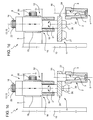
- Number 1 in Figure 1 indicates as a whole a forming section (shown partly) of a machine for producing hollow glass items.
- Forming section 1 comprises a rough mold 2 having one or more mold cavities 3 bounded by respective inner surfaces 4; a known finish mold (not shown); and a take-out and transfer device 5, commonly known as an "invert" and only shown partly in the drawings, for removing one or more semifinished items from rough mold 2 and transferring them to the finish mold by rotating them about a fixed transverse hinge axis.
- a multifunctional group 8 comprising a fixed mounting cross member 9 connected firmly to uprights 10 of section 1, in a raised position with respect to rough mold 2; and a multifunctional head 11.
- Multifunctional group 8 also comprises a handling device 12 for moving multifunctional head 11, to and from cross member 9 and rough mold 2, along a fixed vertical handling axis 13 perpendicular to cross member 9; and a handling device 14 for rotating multifunctional head 11, with respect to cross member 9 and rough mold 2, about a fixed vertical handling axis 15 coincident, in the example shown, with axis 13.
- axes 13 and 15 are parallel and spaced transversely part.
- device 12 comprises a guide-and-slide assembly 16, in turn comprising a vertical guide 18 connected firmly to the cross member, and a hollow slide 19 fitted to guide 18 to run along axis 13 and operated by an electric motor reducer 20.
- a vertical torsion shaft 21 extends through slide 19, is connected to slide 19 in rotary and axially sliding manner, extends coaxially with axis 15, and is rotated in opposite directions about axis 15 and with respect to guide 18 by a known electric rotary actuator 22 not described in detail and forming part of device 14.
- Shaft 21 has an end portion which projects axially from guide 18 towards rough mold 2, and is fitted integrally with multifunctional head 11.
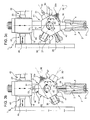
- multifunctional head 11 which is conveniently disk-shaped, extends perpendicularly to axis 15, and comprises a circular plate-like body 23 coaxial with axis 15 and bounded by a flat radial facet 24 adjacent to the outer surface of guide 18.
- An outer peripheral portion 25 of the circular body is fitted integrally with a closing member 26 for closing the top opening of rough mold 2; a funnel-shaped guiding member 27 for guiding at least one glass gob into rough mold 2; and a blowing member 28 for blowing pressurized air into rough mold 2.
- Members 26, 27, 28 extend along respective axes 30 parallel to axes 13 and 15 and arranged angularly along portion 25.
- axes 30 are spaced angularly apart by an angle A of substantially 90° , as shown in Figure 2 .
- axes 30 are spaced angularly apart by angles A ranging between 40° and 90°.
- the head comprises two members for treating the inner surface 4 of the mold and, in particular, a powered mechanical cleaning member 30a for removing scale from surface 4 of rough mold 2 and conveniently interposed between members 26 and 28; and a known spraying member 31, shown schematically, for spraying lubricant onto surface 4 and located between members 26 and 27.
- multifunctional head 11, set to the raised position is rotated about axis 15 to position facet 24 or funnel-shaped member 27 at the inlet of rough mold 2, depending on whether or not the production technology and/or the shape of cavity 3 of rough mold 2 require the use of funnel-shaped member 27 ( Figures 1a and 1d ). If funnel-shaped member 27 is used, head 11 is then moved along axis 13 towards rough mold 2, and funnel-shaped member 27 is connected to rough mold 2, as shown in Figure 1a .
- head 11 if in the lowered position, is raised, is rotated about axis 15 to position axis 30 of blowing member 28 coaxial with the axis of rough mold 2, and is then lowered again so that blowing member 28 closes rough mold 2, as shown in Figure 1b .
- blowing member 28 blows an air jet into rough mold 2 to settle the gob on the bottom of rough mold 2.
- head 11 is raised and rotated about axis 15 to position axis 30 of closing member 26 coaxial with the axis of mold 2, and is then lowered so that closing member 26 closes mold 2, as shown in Figure 1c .
- the gob inside rough mold 2 is deformed in known manner to obtain a corresponding semifinished item.
- head 11 is raised and rotated about axis 15 to position facet 24 at mold 2 ( Figure 1d ), after which, mold 2 is opened and the semifinished item/s extracted by take-out device 5, which rotates to transfer at least the semifinished items facing facet 24 to the finish mold.
- the inner surface of the rough mold is treated by rotating and lowering head 11 to insert member 30a and/or member 31 at least partly inside rough mold 2.
- the Figure 3 embodiment relates to a multifunction group 40, which differs in some respects from multifunctional group 8, and the component parts of which are indicated, where possible, using the same reference numbers as for the corresponding parts of group 8.
- Group 40 comprises a drum-shaped multifunctional head 41 connected to the bottom end of slide 19 and rotated in opposite directions about an axis of rotation 42, perpendicular to axis 13, by an electric motor reducer device 43 shown schematically.
- Slide 19 is again connected to guide 18, which, in group 40, is connected to cross member 9 with the interposition of a further guide-and-slide device 45 for moving guide 18, and therefore slide 19 and head 41, in a direction 46 parallel to cross member 9 and perpendicular to axes 13 and 42.
- head 41 is hexagonal and bounded laterally by a number of faces 47, from some of which funnel-shaped member 27, blowing member 28, closing member 26, mechanical cleaning member 30a and lubricant spraying member 31 project radially, so that axes 30 of the various members extend perpendicular to axis 42 and form angles B of substantially 45° with one another.
- head 41 is raised to prevent members 26-28 from contacting mold 2, is then rotated in steps about axis 42 to successively position members 26-28, each with its axis 30 coincident with the axis of rough mold 2, and is then lowered to connect the various members to rough mold 2 in the sequence described for multifunctional head 11.
- head 41, together with slide 19, is moved by device 45 in direction 46 to obtain free access to the inlet of rough mold 2.
- head 41 is relieved of one of the members - in this case, member 31 - and is milled to form a cut-away face 50 of the type, for example, shown by the dash line in Figure 3 .
- head 41 and slide 19 are withdrawn in direction 46 from the inlet of mold 2 before extracting and transferring the semifinished item to the finish mold.
- head 41 is withdrawn from the inlet of rough mold 2 by simply moving head 41 along axis 13 towards cross member 9.
- multifunctional groups 8 and 40 described therefore provide, above all, for reducing the on-board bulk of the machine, thus greatly simplifying control of members 26, 27, 28, 30a and 31.
- members 26, 27, 28, 30a, 31 are all controlled by electric motors, with no dedicated pneumatic and/or cam mechanisms for each member as in known solutions.
- multifunctional groups 8, 40 as opposed to independent single mechanisms, as in known solutions, also provides for fast function changeover and, therefore, faster output of section 1 and the machine as a whole.
- Combining the various members of the rough mold into one group also provides, as compared with known solutions with separate, independent members, not only for much faster machine assembly but also, and above all, for faster reconfiguration when making production and/or mold changes.
- fitting members 26, 27, 28, 30a, 31 to one supporting head and connecting the head to one cross member greatly reduces overall weight, while at the same time achieving a group that is simple in design and cheap to produce, and also increasing the space available to the mechanisms arranged about the multifunctional head.
- supporting heads 11 and 41 may differ in shape and geometry from those indicated by way of example, the various members may be arranged differently on the head, and the number and type of members fitted to heads 11 and 41 may differ. More specifically, heads 11 and 41 may support one or more multifunctional members, i.e. each for performing two different functions, such as the closing function of closing member 26, and the blowing function of blowing member 28.
- Devices 12, 14, 43, 45 for moving heads 11 and 41 may also differ from those described by way of example, and may comprise relative-motion assemblies other than but technically equivalent to those described, e.g. an articulated arm fitted, or not, to slide devices.
Landscapes
- Engineering & Computer Science (AREA)
- Chemical & Material Sciences (AREA)
- Manufacturing & Machinery (AREA)
- Materials Engineering (AREA)
- Organic Chemistry (AREA)
- Moulds For Moulding Plastics Or The Like (AREA)
- Re-Forming, After-Treatment, Cutting And Transporting Of Glass Products (AREA)
- Processing And Handling Of Plastics And Other Materials For Molding In General (AREA)
- Injection Moulding Of Plastics Or The Like (AREA)
Claims (17)
- Multifunktionelle so ausgestaltete Gruppe (8), dass sie zu einer Rohform (2) einer Glaswarenformmaschine vom Typ I.S. gehört,
wobei die Gruppe (8) umfasst:einen gemeinsamen Stützkopf (11), erste Handhabungsmittel (18), die ausgestaltet sind, um den gemeinsamen Kopf entlang einer ersten Handhabungsachse (13) zu bewegen, und zweite Handhabungsmittel (14), die ausgestaltet sind, um den gemeinsamen Kopf um eine zweite Handhabungsachse (13; 42) zu drehen; ein von dem gemeinsamen Kopf (11) getragenes Schließelement (26), das ausgestaltet ist, um die obere Öffnung der Rohform (2) zu verschließen, und zumindest ein weiteres Arbeitselement, das ebenfalls von dem gemeinsamen Kopf getragen ist und zwischen einem trichterförmigen Führungselement (27) zum Hineinführen zumindest eines Glastropfens in die Rohform (2), einem Blaselement (28) zum Hineinblasen eines druckluftbeaufschlagten Luftstroms in die Rohform (2) und Oberflächenbehandlungs-Elementen (30a, 31) zum Behandeln der Innenfläche (4) der Rohform (2) umschaltbar ist. - Gruppe nach Anspruch 1, dadurch gekennzeichnet, dass der gemeinsame Stützkopf auch das Blaselement (28) in gekoppeltem Betriebszustand trägt.
- Gruppe nach Anspruch 1 oder 2, dadurch gekennzeichnet, dass der gemeinsame Stützkopf das trichterförmige Element (27) in gekoppeltem Betriebszustand trägt.
- Gruppe nach einem der Ansprüche 1 bis 3, dadurch gekennzeichnet, dass der gemeinsame Stützkopf (11) in gekoppeltem Betriebszustand ein bzw. mehrere Oberflächenbehandlungs-Elemente (30a; 31) zum Behandeln der Innenfläche (4) der Rohform (2) trägt.
- Multifunktionelle Gruppe nach einem der vorherigen Ansprüche, dadurch gekennzeichnet, dass zumindest ein Teil der von dem gemeinsamen Stützkopf (11) getragenen Elemente integral mit einem äußeren Randabschnitt des gemeinsamen Stützkopfes (11) zum Zusammenbewegen mit den gemeinsamen Stützkopf (11) verbunden ist.
- Gruppe nach einem der vorherigen Ansprüche, dadurch gekennzeichnet, dass die erste Handhabungsachse (13) eine vertikale Achse ist.
- Gruppe nach einem der vorherigen Ansprüche, dadurch gekennzeichnet, dass die zweite Handhabungsachse eine vertikale Achse (13) ist.
- Gruppe nach einem der vorherigen Ansprüche, dadurch gekennzeichnet, dass die erste Handhabungsachse mit der zweiten Handhabungsachse zusammenfällt.
- Gruppe nach einem der vorherigen Ansprüche, dadurch gekennzeichnet, dass der gemeinsame Stützkopf (11) eine radiale Aussparung (24) aufweist, die ausgestaltet ist, um von einem Inverterelement (5) zum Extrahieren der Glaswaren aus der Rohform (2) oder von einem in Richtung der Rohform (2) weisenden Glasposten gekreuzt wird.
- Gruppe nach einem der vorherigen Ansprüche, dadurch gekennzeichnet, dass sich die von dem gemeinsamen Stützkopf (11) getragenen Elemente axial von dem Kopf zu entsprechenden Längsachsen (30) erstrecken, die parallel zu der ersten Achse (13) und zu der zweiten Achse (14) verlaufen.
- Gruppe nach den Ansprüchen 1 bis 6, dadurch gekennzeichnet, dass die zweite Handhabungsachse (42) eine horizontale Achse ist.
- Gruppe nach Anspruch 11, dadurch gekennzeichnet, dass sich die von dem gemeinsamen Stützkopf (11) getragenen Elemente freitragend von dem gemeinsamen Stützkopf (11) entlang entsprechender Radialachsen (30) lotrecht zu der zweiten Handhabungsachse (42) erstrecken.
- Gruppe nach einem der vorherigen Ansprüche, dadurch gekennzeichnet, dass die Winkel der Verlängerungsachsen der Elemente durch einen sich von vierzig bis neunzig Grad verändernden Winkel voneinander beabstandet sind.
- Gruppe nach einem der vorherigen Ansprüche, dadurch gekennzeichnet, dass die sich von dem gemeinsamen Stützkopf (11) getragenen Elemente im Wesentlichen entlang des halben Randaußenabschnitts des Stützkopfs (11) angeordnet sind.
- Gruppe nach einem der vorherigen Ansprüche, dadurch gekennzeichnet, dass der gemeinsame Stützkopf (11) unterschiedliche Facettierungen (47) an seinem Außenrand aufweist und dass sich eines der zugehörigen Elemente zumindest von einem Teil der Facettierungen (47) aus erstreckt.
- Gebrauch einer multifunktionellen Gruppe nach Anspruch 1, die benachbart einer Rohform (2) einer Hohlglaswaren-Formmaschine des Typs I.S. positioniert ist.
- Hohlglaswaren-Formmaschine des Typs I.S., wobei die Maschine des Typs I.S. zumindest eine Hohlform (2) umfasst und dadurch gekennzeichnet ist, dass sie weiterhin eine der Rohform (2) benachbarte multifunktionelle Gruppe (8) zur Kopplung mit der Rohform (2) und zur Ausführung nach Anspruch 1 umfasst.
Applications Claiming Priority (1)
| Application Number | Priority Date | Filing Date | Title |
|---|---|---|---|
| ITTO2008A000550A IT1390912B1 (it) | 2008-07-17 | 2008-07-17 | Gruppo multifunzione di una macchina di formatura di articoli di vetro |
Publications (2)
| Publication Number | Publication Date |
|---|---|
| EP2145859A1 EP2145859A1 (de) | 2010-01-20 |
| EP2145859B1 true EP2145859B1 (de) | 2011-10-26 |
Family
ID=40718828
Family Applications (1)
| Application Number | Title | Priority Date | Filing Date |
|---|---|---|---|
| EP09165845A Not-in-force EP2145859B1 (de) | 2008-07-17 | 2009-07-17 | Multifunktionelle Gruppe für eine Glaselementformmaschine |
Country Status (4)
| Country | Link |
|---|---|
| US (2) | US8341977B2 (de) |
| EP (1) | EP2145859B1 (de) |
| AT (1) | ATE530501T1 (de) |
| IT (1) | IT1390912B1 (de) |
Families Citing this family (2)
| Publication number | Priority date | Publication date | Assignee | Title |
|---|---|---|---|---|
| IT1390912B1 (it) * | 2008-07-17 | 2011-10-19 | Bottero Spa | Gruppo multifunzione di una macchina di formatura di articoli di vetro |
| CN105527744B (zh) * | 2016-02-01 | 2018-10-26 | 武汉华星光电技术有限公司 | 彩膜基板的制作方法 |
Family Cites Families (24)
| Publication number | Priority date | Publication date | Assignee | Title |
|---|---|---|---|---|
| US3125429A (en) * | 1964-03-17 | Xf nexk finish | ||
| US1911119A (en) * | 1928-05-04 | 1933-05-23 | Hartford Empire Co | Glassware forming machine |
| US3536468A (en) * | 1967-12-14 | 1970-10-27 | Owens Illinois Inc | Glass parison forming with settle blow closing means |
| US4013437A (en) * | 1975-05-15 | 1977-03-22 | Owens-Illinois, Inc. | Method for forming glass bottles |
| US4004905A (en) * | 1975-11-21 | 1977-01-25 | Owens-Illinois, Inc. | Safety lock for forming machine blowhead |
| US4120683A (en) * | 1977-08-01 | 1978-10-17 | Owens-Illinois, Inc. | Funnel arm operating mechanism |
| US4191548A (en) * | 1978-05-17 | 1980-03-04 | Owens-Illinois, Inc. | Method and apparatus for forming glass containers |
| US4362544A (en) * | 1981-07-24 | 1982-12-07 | Owens-Illinois, Inc. | Fluid control system for glassware forming machine |
| US4444578A (en) * | 1981-10-09 | 1984-04-24 | Vitro Tec Fideicomiso | Parison mold and baffle system for an automatic molding machine |
| GB2144732B (en) * | 1983-08-13 | 1986-09-10 | Emhart Ind | Distributing gobs in a glassware manufacturing machine |
| US4610713A (en) * | 1984-12-24 | 1986-09-09 | Clegg Wallace H | Settle blow head and baffle arm attachment for glassware molding machine |
| GB2178025B (en) * | 1985-07-24 | 1988-10-05 | Emhart Ind | Moving mechanism for use in a glassware manufacturing machine of the individual section type |
| US4765821A (en) * | 1987-01-30 | 1988-08-23 | Ball Corporation | Apparatus for lubricating glassware mold |
| JPH065383Y2 (ja) * | 1988-12-06 | 1994-02-09 | 株式会社エヌテック | ガラス製壜機の金型潤滑液塗布装置 |
| CA2078380C (en) * | 1991-09-17 | 1998-05-19 | Victor Tijerina-Ramos | Machine for the production of glassware articles by the press and blow process |
| US5769920A (en) * | 1992-08-27 | 1998-06-23 | Union Oil Company Of California | Graphite guide rings |
| IT1265575B1 (it) * | 1993-10-11 | 1996-11-22 | Co Ge Ve Spa | Dispositivo di scovolatura automatica in stampi di formatura di vetro e relativo processo di scovolatura |
| AU665905B2 (en) * | 1994-05-02 | 1996-01-18 | Yamamura Glass Co., Ltd. | Swabbing device for molds of bottle making machine |
| US5858050A (en) * | 1997-11-06 | 1999-01-12 | Emhart Glass S.A. | I.S. machine |
| US6240747B1 (en) * | 1997-11-06 | 2001-06-05 | Emhart Glass S.A. | Baffle mechanism for I.S. machine |
| US5958101A (en) * | 1997-11-06 | 1999-09-28 | Emhart Glass S.A. | Mold opening and closing mechanism for an I.S. machine |
| US6902708B1 (en) * | 2000-04-25 | 2005-06-07 | Air Liquide America Corporation | Method and apparatus for making carbon black |
| US8166779B2 (en) * | 2006-10-13 | 2012-05-01 | Owens-Brockway Glass Container Inc. | Baffle system for blank molds of a glassware forming machine |
| IT1390912B1 (it) * | 2008-07-17 | 2011-10-19 | Bottero Spa | Gruppo multifunzione di una macchina di formatura di articoli di vetro |
-
2008
- 2008-07-17 IT ITTO2008A000550A patent/IT1390912B1/it active
-
2009
- 2009-07-17 US US12/460,363 patent/US8341977B2/en not_active Expired - Fee Related
- 2009-07-17 AT AT09165845T patent/ATE530501T1/de not_active IP Right Cessation
- 2009-07-17 EP EP09165845A patent/EP2145859B1/de not_active Not-in-force
-
2012
- 2012-12-04 US US13/693,587 patent/US8650909B2/en not_active Expired - Fee Related
Also Published As
| Publication number | Publication date |
|---|---|
| US20130160494A1 (en) | 2013-06-27 |
| US8650909B2 (en) | 2014-02-18 |
| US8341977B2 (en) | 2013-01-01 |
| IT1390912B1 (it) | 2011-10-19 |
| ITTO20080550A1 (it) | 2010-01-18 |
| US20100018254A1 (en) | 2010-01-28 |
| ATE530501T1 (de) | 2011-11-15 |
| EP2145859A1 (de) | 2010-01-20 |
Similar Documents
| Publication | Publication Date | Title |
|---|---|---|
| RU2307077C2 (ru) | Способ и машина для производства полых стеклянных изделий | |
| CN101190646B (zh) | 用于将充气轮胎安装在车轮轮辋上的设备 | |
| US7766645B2 (en) | Method of controlling the opening and closing of a blow mold and blowing device for implementing same | |
| EP4043181A1 (de) | Vollpleuelmechanismus für die verbindung zwischen öffnungs- und schliessform und bodenform einer flaschenblasmaschine | |
| EP3718741B1 (de) | Öffenbare/schliessbare form- und grundformgestängevorrichtung einer flaschenblasmaschine | |
| EP2145859B1 (de) | Multifunktionelle Gruppe für eine Glaselementformmaschine | |
| US8631926B2 (en) | Device for pushing glass objects onto a conveyor belt | |
| KR20010040743A (ko) | 목부분을 포함하는 중공체 이동 장치 | |
| EP0195599A1 (de) | Vorrichtung zum Öffnen und zum Schliessen von Matrizen in einer Maschine zum Herstellen von Glasgegenständen | |
| EP1627859B1 (de) | Vorschubvorrichtung zum Vorschieben von Glaswaren | |
| US20110314872A1 (en) | Glassware forming machine molds opening/closing device | |
| CN111645302A (zh) | 一种吹瓶机动边模与底模联动的组合连杆机构 | |
| US7264108B2 (en) | Transfer unit for transferring glass articles | |
| CA2545301A1 (en) | Articulated arm transport device | |
| HUP0104850A2 (en) | Apparatus for forming glass containers | |
| US8113016B2 (en) | Molds opening/closing group of a forming glass machine items | |
| EP2226297B1 (de) | Anordnung zum Öffnen/Schließen der Formen einer Glaswarenformmaschine | |
| EP2108623A2 (de) | Transferanordnung zum Transfer von Glasartikeln | |
| EP2047964B1 (de) | Injektionsblasformungsmaschine und entsprechendes Verfahren | |
| US9527762B2 (en) | Apparatus for pressing and placing glass preforms | |
| CN116160320A (zh) | 一种面向光学器件磨抛加工的可重构混联机器人 | |
| JP2001019443A (ja) | 製びん機の金型開閉装置 | |
| CN114179336B (zh) | 旋转式吹瓶机开合模与底模联动结构及吹瓶机 | |
| CN111055204A (zh) | 一种自动化上下料的断差机 | |
| EP3428131B1 (de) | Verfahren und mechanismus zum öffnen und schliessen von formen für eine maschine zum formen von glasartikeln |
Legal Events
| Date | Code | Title | Description |
|---|---|---|---|
| PUAI | Public reference made under article 153(3) epc to a published international application that has entered the european phase |
Free format text: ORIGINAL CODE: 0009012 |
|
| AK | Designated contracting states |
Kind code of ref document: A1 Designated state(s): AT BE BG CH CY CZ DE DK EE ES FI FR GB GR HR HU IE IS IT LI LT LU LV MC MK MT NL NO PL PT RO SE SI SK SM TR |
|
| AX | Request for extension of the european patent |
Extension state: AL BA RS |
|
| 17P | Request for examination filed |
Effective date: 20100720 |
|
| 17Q | First examination report despatched |
Effective date: 20100927 |
|
| GRAP | Despatch of communication of intention to grant a patent |
Free format text: ORIGINAL CODE: EPIDOSNIGR1 |
|
| GRAS | Grant fee paid |
Free format text: ORIGINAL CODE: EPIDOSNIGR3 |
|
| GRAA | (expected) grant |
Free format text: ORIGINAL CODE: 0009210 |
|
| AK | Designated contracting states |
Kind code of ref document: B1 Designated state(s): AT BE BG CH CY CZ DE DK EE ES FI FR GB GR HR HU IE IS IT LI LT LU LV MC MK MT NL NO PL PT RO SE SI SK SM TR |
|
| REG | Reference to a national code |
Ref country code: GB Ref legal event code: FG4D |
|
| REG | Reference to a national code |
Ref country code: CH Ref legal event code: EP |
|
| REG | Reference to a national code |
Ref country code: IE Ref legal event code: FG4D |
|
| REG | Reference to a national code |
Ref country code: DE Ref legal event code: R096 Ref document number: 602009003276 Country of ref document: DE Effective date: 20120105 |
|
| REG | Reference to a national code |
Ref country code: CH Ref legal event code: NV Representative=s name: CABINET ROLAND NITHARDT CONSEILS EN PROPRIETE INDU |
|
| REG | Reference to a national code |
Ref country code: SE Ref legal event code: TRGR |
|
| REG | Reference to a national code |
Ref country code: NL Ref legal event code: VDEP Effective date: 20111026 |
|
| LTIE | Lt: invalidation of european patent or patent extension |
Effective date: 20111026 |
|
| REG | Reference to a national code |
Ref country code: AT Ref legal event code: MK05 Ref document number: 530501 Country of ref document: AT Kind code of ref document: T Effective date: 20111026 |
|
| PG25 | Lapsed in a contracting state [announced via postgrant information from national office to epo] |
Ref country code: LT Free format text: LAPSE BECAUSE OF FAILURE TO SUBMIT A TRANSLATION OF THE DESCRIPTION OR TO PAY THE FEE WITHIN THE PRESCRIBED TIME-LIMIT Effective date: 20111026 Ref country code: IS Free format text: LAPSE BECAUSE OF FAILURE TO SUBMIT A TRANSLATION OF THE DESCRIPTION OR TO PAY THE FEE WITHIN THE PRESCRIBED TIME-LIMIT Effective date: 20120226 Ref country code: NO Free format text: LAPSE BECAUSE OF FAILURE TO SUBMIT A TRANSLATION OF THE DESCRIPTION OR TO PAY THE FEE WITHIN THE PRESCRIBED TIME-LIMIT Effective date: 20120126 Ref country code: BE Free format text: LAPSE BECAUSE OF FAILURE TO SUBMIT A TRANSLATION OF THE DESCRIPTION OR TO PAY THE FEE WITHIN THE PRESCRIBED TIME-LIMIT Effective date: 20111026 |
|
| PG25 | Lapsed in a contracting state [announced via postgrant information from national office to epo] |
Ref country code: HR Free format text: LAPSE BECAUSE OF FAILURE TO SUBMIT A TRANSLATION OF THE DESCRIPTION OR TO PAY THE FEE WITHIN THE PRESCRIBED TIME-LIMIT Effective date: 20111026 Ref country code: SI Free format text: LAPSE BECAUSE OF FAILURE TO SUBMIT A TRANSLATION OF THE DESCRIPTION OR TO PAY THE FEE WITHIN THE PRESCRIBED TIME-LIMIT Effective date: 20111026 Ref country code: LV Free format text: LAPSE BECAUSE OF FAILURE TO SUBMIT A TRANSLATION OF THE DESCRIPTION OR TO PAY THE FEE WITHIN THE PRESCRIBED TIME-LIMIT Effective date: 20111026 Ref country code: PL Free format text: LAPSE BECAUSE OF FAILURE TO SUBMIT A TRANSLATION OF THE DESCRIPTION OR TO PAY THE FEE WITHIN THE PRESCRIBED TIME-LIMIT Effective date: 20111026 Ref country code: NL Free format text: LAPSE BECAUSE OF FAILURE TO SUBMIT A TRANSLATION OF THE DESCRIPTION OR TO PAY THE FEE WITHIN THE PRESCRIBED TIME-LIMIT Effective date: 20111026 Ref country code: GR Free format text: LAPSE BECAUSE OF FAILURE TO SUBMIT A TRANSLATION OF THE DESCRIPTION OR TO PAY THE FEE WITHIN THE PRESCRIBED TIME-LIMIT Effective date: 20120127 Ref country code: PT Free format text: LAPSE BECAUSE OF FAILURE TO SUBMIT A TRANSLATION OF THE DESCRIPTION OR TO PAY THE FEE WITHIN THE PRESCRIBED TIME-LIMIT Effective date: 20120227 |
|
| PG25 | Lapsed in a contracting state [announced via postgrant information from national office to epo] |
Ref country code: CY Free format text: LAPSE BECAUSE OF FAILURE TO SUBMIT A TRANSLATION OF THE DESCRIPTION OR TO PAY THE FEE WITHIN THE PRESCRIBED TIME-LIMIT Effective date: 20111026 |
|
| PG25 | Lapsed in a contracting state [announced via postgrant information from national office to epo] |
Ref country code: EE Free format text: LAPSE BECAUSE OF FAILURE TO SUBMIT A TRANSLATION OF THE DESCRIPTION OR TO PAY THE FEE WITHIN THE PRESCRIBED TIME-LIMIT Effective date: 20111026 Ref country code: SK Free format text: LAPSE BECAUSE OF FAILURE TO SUBMIT A TRANSLATION OF THE DESCRIPTION OR TO PAY THE FEE WITHIN THE PRESCRIBED TIME-LIMIT Effective date: 20111026 Ref country code: BG Free format text: LAPSE BECAUSE OF FAILURE TO SUBMIT A TRANSLATION OF THE DESCRIPTION OR TO PAY THE FEE WITHIN THE PRESCRIBED TIME-LIMIT Effective date: 20120126 Ref country code: DK Free format text: LAPSE BECAUSE OF FAILURE TO SUBMIT A TRANSLATION OF THE DESCRIPTION OR TO PAY THE FEE WITHIN THE PRESCRIBED TIME-LIMIT Effective date: 20111026 |
|
| PG25 | Lapsed in a contracting state [announced via postgrant information from national office to epo] |
Ref country code: RO Free format text: LAPSE BECAUSE OF FAILURE TO SUBMIT A TRANSLATION OF THE DESCRIPTION OR TO PAY THE FEE WITHIN THE PRESCRIBED TIME-LIMIT Effective date: 20111026 Ref country code: IT Free format text: LAPSE BECAUSE OF FAILURE TO SUBMIT A TRANSLATION OF THE DESCRIPTION OR TO PAY THE FEE WITHIN THE PRESCRIBED TIME-LIMIT Effective date: 20111026 |
|
| PLBE | No opposition filed within time limit |
Free format text: ORIGINAL CODE: 0009261 |
|
| STAA | Information on the status of an ep patent application or granted ep patent |
Free format text: STATUS: NO OPPOSITION FILED WITHIN TIME LIMIT |
|
| 26N | No opposition filed |
Effective date: 20120727 |
|
| REG | Reference to a national code |
Ref country code: DE Ref legal event code: R097 Ref document number: 602009003276 Country of ref document: DE Effective date: 20120727 |
|
| PG25 | Lapsed in a contracting state [announced via postgrant information from national office to epo] |
Ref country code: AT Free format text: LAPSE BECAUSE OF FAILURE TO SUBMIT A TRANSLATION OF THE DESCRIPTION OR TO PAY THE FEE WITHIN THE PRESCRIBED TIME-LIMIT Effective date: 20111026 |
|
| PG25 | Lapsed in a contracting state [announced via postgrant information from national office to epo] |
Ref country code: MC Free format text: LAPSE BECAUSE OF NON-PAYMENT OF DUE FEES Effective date: 20120731 Ref country code: MK Free format text: LAPSE BECAUSE OF FAILURE TO SUBMIT A TRANSLATION OF THE DESCRIPTION OR TO PAY THE FEE WITHIN THE PRESCRIBED TIME-LIMIT Effective date: 20111026 |
|
| REG | Reference to a national code |
Ref country code: FR Ref legal event code: ST Effective date: 20130329 |
|
| PG25 | Lapsed in a contracting state [announced via postgrant information from national office to epo] |
Ref country code: ES Free format text: LAPSE BECAUSE OF FAILURE TO SUBMIT A TRANSLATION OF THE DESCRIPTION OR TO PAY THE FEE WITHIN THE PRESCRIBED TIME-LIMIT Effective date: 20120206 Ref country code: FR Free format text: LAPSE BECAUSE OF NON-PAYMENT OF DUE FEES Effective date: 20120731 |
|
| REG | Reference to a national code |
Ref country code: IE Ref legal event code: MM4A |
|
| PG25 | Lapsed in a contracting state [announced via postgrant information from national office to epo] |
Ref country code: FI Free format text: LAPSE BECAUSE OF FAILURE TO SUBMIT A TRANSLATION OF THE DESCRIPTION OR TO PAY THE FEE WITHIN THE PRESCRIBED TIME-LIMIT Effective date: 20111026 |
|
| PG25 | Lapsed in a contracting state [announced via postgrant information from national office to epo] |
Ref country code: IE Free format text: LAPSE BECAUSE OF NON-PAYMENT OF DUE FEES Effective date: 20120717 Ref country code: MT Free format text: LAPSE BECAUSE OF FAILURE TO SUBMIT A TRANSLATION OF THE DESCRIPTION OR TO PAY THE FEE WITHIN THE PRESCRIBED TIME-LIMIT Effective date: 20111026 |
|
| GBPC | Gb: european patent ceased through non-payment of renewal fee |
Effective date: 20130717 |
|
| PG25 | Lapsed in a contracting state [announced via postgrant information from national office to epo] |
Ref country code: GB Free format text: LAPSE BECAUSE OF NON-PAYMENT OF DUE FEES Effective date: 20130717 Ref country code: TR Free format text: LAPSE BECAUSE OF FAILURE TO SUBMIT A TRANSLATION OF THE DESCRIPTION OR TO PAY THE FEE WITHIN THE PRESCRIBED TIME-LIMIT Effective date: 20111026 |
|
| PG25 | Lapsed in a contracting state [announced via postgrant information from national office to epo] |
Ref country code: SM Free format text: LAPSE BECAUSE OF FAILURE TO SUBMIT A TRANSLATION OF THE DESCRIPTION OR TO PAY THE FEE WITHIN THE PRESCRIBED TIME-LIMIT Effective date: 20111026 Ref country code: LU Free format text: LAPSE BECAUSE OF NON-PAYMENT OF DUE FEES Effective date: 20120717 |
|
| PG25 | Lapsed in a contracting state [announced via postgrant information from national office to epo] |
Ref country code: HU Free format text: LAPSE BECAUSE OF FAILURE TO SUBMIT A TRANSLATION OF THE DESCRIPTION OR TO PAY THE FEE WITHIN THE PRESCRIBED TIME-LIMIT Effective date: 20090717 |
|
| REG | Reference to a national code |
Ref country code: CH Ref legal event code: NV Representative=s name: ACTOSPHERE SARL, CH |
|
| PGFP | Annual fee paid to national office [announced via postgrant information from national office to epo] |
Ref country code: CH Payment date: 20200623 Year of fee payment: 12 Ref country code: CZ Payment date: 20200626 Year of fee payment: 12 |
|
| PGFP | Annual fee paid to national office [announced via postgrant information from national office to epo] |
Ref country code: SE Payment date: 20200626 Year of fee payment: 12 |
|
| PGFP | Annual fee paid to national office [announced via postgrant information from national office to epo] |
Ref country code: DE Payment date: 20200622 Year of fee payment: 12 |
|
| REG | Reference to a national code |
Ref country code: DE Ref legal event code: R119 Ref document number: 602009003276 Country of ref document: DE |
|
| REG | Reference to a national code |
Ref country code: CH Ref legal event code: PL |
|
| PG25 | Lapsed in a contracting state [announced via postgrant information from national office to epo] |
Ref country code: LI Free format text: LAPSE BECAUSE OF NON-PAYMENT OF DUE FEES Effective date: 20210731 Ref country code: DE Free format text: LAPSE BECAUSE OF NON-PAYMENT OF DUE FEES Effective date: 20220201 Ref country code: CH Free format text: LAPSE BECAUSE OF NON-PAYMENT OF DUE FEES Effective date: 20210731 |
|
| PG25 | Lapsed in a contracting state [announced via postgrant information from national office to epo] |
Ref country code: SE Free format text: LAPSE BECAUSE OF NON-PAYMENT OF DUE FEES Effective date: 20210718 Ref country code: CZ Free format text: LAPSE BECAUSE OF NON-PAYMENT OF DUE FEES Effective date: 20210717 |