EP2145657B1 - Exercise machine - Google Patents
Exercise machine Download PDFInfo
- Publication number
- EP2145657B1 EP2145657B1 EP09165763A EP09165763A EP2145657B1 EP 2145657 B1 EP2145657 B1 EP 2145657B1 EP 09165763 A EP09165763 A EP 09165763A EP 09165763 A EP09165763 A EP 09165763A EP 2145657 B1 EP2145657 B1 EP 2145657B1
- Authority
- EP
- European Patent Office
- Prior art keywords
- motion
- unit
- exercise machine
- main body
- driver
- Prior art date
- Legal status (The legal status is an assumption and is not a legal conclusion. Google has not performed a legal analysis and makes no representation as to the accuracy of the status listed.)
- Active
Links
Images


Classifications
-
- A—HUMAN NECESSITIES
- A63—SPORTS; GAMES; AMUSEMENTS
- A63B—APPARATUS FOR PHYSICAL TRAINING, GYMNASTICS, SWIMMING, CLIMBING, OR FENCING; BALL GAMES; TRAINING EQUIPMENT
- A63B23/00—Exercising apparatus specially adapted for particular parts of the body
- A63B23/035—Exercising apparatus specially adapted for particular parts of the body for limbs, i.e. upper or lower limbs, e.g. simultaneously
- A63B23/12—Exercising apparatus specially adapted for particular parts of the body for limbs, i.e. upper or lower limbs, e.g. simultaneously for upper limbs or related muscles, e.g. chest, upper back or shoulder muscles
-
- A—HUMAN NECESSITIES
- A63—SPORTS; GAMES; AMUSEMENTS
- A63B—APPARATUS FOR PHYSICAL TRAINING, GYMNASTICS, SWIMMING, CLIMBING, OR FENCING; BALL GAMES; TRAINING EQUIPMENT
- A63B69/00—Training appliances or apparatus for special sports
- A63B69/04—Training appliances or apparatus for special sports simulating the movement of horses
-
- A—HUMAN NECESSITIES
- A63—SPORTS; GAMES; AMUSEMENTS
- A63B—APPARATUS FOR PHYSICAL TRAINING, GYMNASTICS, SWIMMING, CLIMBING, OR FENCING; BALL GAMES; TRAINING EQUIPMENT
- A63B22/00—Exercising apparatus specially adapted for conditioning the cardio-vascular system, for training agility or co-ordination of movements
- A63B22/06—Exercising apparatus specially adapted for conditioning the cardio-vascular system, for training agility or co-ordination of movements with support elements performing a rotating cycling movement, i.e. a closed path movement
-
- A—HUMAN NECESSITIES
- A63—SPORTS; GAMES; AMUSEMENTS
- A63B—APPARATUS FOR PHYSICAL TRAINING, GYMNASTICS, SWIMMING, CLIMBING, OR FENCING; BALL GAMES; TRAINING EQUIPMENT
- A63B22/00—Exercising apparatus specially adapted for conditioning the cardio-vascular system, for training agility or co-ordination of movements
- A63B22/18—Exercising apparatus specially adapted for conditioning the cardio-vascular system, for training agility or co-ordination of movements with elements, i.e. platforms, having a circulating, nutating or rotating movement, generated by oscillating movement of the user, e.g. platforms wobbling on a centrally arranged spherical support
Definitions
- the present invention relates to an exercise machine, and more particularly, to an exercise machine which performs translational reciprocating motions and pivotal reciprocating motions in plural directions.
- exercise machines for example, a running machine, a stepping device, and an indoor bicycle, for maintaining or promoting one's health and physical strength are widely used.
- US6964614 discloses an exercise machine comprising a support defining a longitudinal direction and a transverse direction; a first motion unit coupled to the support to provide a pivotal movement of the first motion unit in the transverse direction; a second motion unit coupled to the first motion unit to provide one of a translational movement and a pivotal movement of the second motion unit in the longitudinal direction; and a driver configured to impart movement to the first motion unit and the second motion unit.
- the present invention has been made in an effort to solve the above problems, and the present invention provides an exercise machine for performing a translational reciprocating motion and a pivotal reciprocating motion using a translational reciprocating motion direction as a rotation axis.
- the present invention further provides an exercise machine for performing a pivotal reciprocating motion in which the rotation axis changes.
- An embodiment of the invention further provides an exercise machine that can change or stop a motion using a clutch.
- an exercise machine including a support defining a longitudinal direction and a transverse direction, a first motion unit coupled to the support to provide a combined translational and pivotal movement of the first motion unit in the transverse direction, a second motion unit coupled to the first motion unit to provide one of a translational movement and a pivotal movement of the second motion unit in the longitudinal direction, and a driving source configured to impart movement to the first and second motion units.
- the first motion unit may include a first main body, and a pair of linkage arms connecting the first main body to the support, the combination of the pair of linkage arms, the first main body, and the support form a four-bar linkage.
- FIG. 1 shows a right front perspective view of an exercise machine according to an exemplary embodiment of the present invention
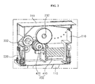
- FIG. 2 shows a cross-sectional view of the exercise machine of FIG. 1 ;
- FIGS. 3 and 4 show front views demonstrating the operation of a first motion unit of the exercise machine of FIG. 1 ;
- FIGS. 5(a) and 5(b) show schematic views of alternative arrangements of a first coupling unit of the exercise machine according to an exemplary embodiment of the present invention:
- FIG. 6 shows a perspective view of a clutch for an exercise machine according to another exemplary embodiment of the present invention.
- the exercise machine includes a support 110, a first motion unit 200 coupled to the support 110 to perform combined translational and pivotal reciprocating motions, a second motion unit 300 coupled to the first motion unit 200 to perform at least one of translational and pivotal reciprocating motions, and a driver 400 for driving the first motion unit 200 and the second motion unit 300.
- the support 110 supports the first motion unit 200 and the second motion unit 300. It is preferable that the support 110 supports the exercise machine at the floor in a way that reduces shaking when the first motion unit 200 and the second motion unit 300 perform reciprocating motions. Further. the support 110 should support the exercise machine to prevent the exercise machine from falling when a person sits at the upper side of the second motion unit 300 and the exercise machine is in operation. It is preferable that the support 110 has a long foothold to support the exercise machine at the floor.
- the first motion unit 200 is coupled to the support 110 to perform translational and pivotal reciprocating motions in a transverse (side-to-side) direction.
- the first motion unit 200 is coupled to the support 110 to perform a pivotal reciprocating motion in which the pivot axis changes in the transverse direction.
- the first motion unit 200 performs a translational reciprocating motion as the pivot axis of the pivotal reciprocating motion changes. Accordingly, the first motion unit 200 performs a combined translational reciprocating motion in the transverse direction and pivotal reciprocating motions in the transverse direction. Further. the first motion unit 200 performs a reciprocating motion in a vertical direction.
- the first motion unit 200 includes a first motion main body 210 provided at the upper side of the support 110, a first transmission unit 230 for transferring the rotary power of the driver 400 to convert the rotary power to a reciprocating motion, and a first coupling unit 220 for connecting the first motion main body 210 to the support 110 so that the first motion main body 210 performs the combined translational and pivotal reciprocating motion in the transverse direction.
- the first motion main body 210 is provided at the upper side of the support 110 and forms a main body of the first motion unit 200.
- the driver 400 for generating the rotary power is provided within the first motion main body 210.
- the first motion main body 210 is pivotally coupled to the first transmission unit 230.
- the first motion main body 210 performs a pivotal reciprocating motion by being coupled to the first coupling unit 220.
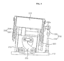
- the first transmission unit 230 transfers the rotary power of the driver 400 and converts the rotary power to a reciprocating motion. In the described embodiment, only a singe transmission unit 230 is provided at the left side or the right side of the first motion main body 210. The first transmission unit 230 will be described later in detail with reference to FIGS. 3 and 4 .
- the first coupling unit 220 connects the first motion main body 210 to the support 110 so that the first motion main body 210 performs a translational and pivotal reciprocating motion in a transverse direction.
- the first coupling unit 220 is formed with a plurality of revolute joints and the first motion main body 210 performs a pivotal reciprocating motion while changing the pivot axis in a transverse direction.
- the first coupling unit 220 allows the first motion main body 210 to perform a pivotal reciprocating motion as well as a translational reciprocating motion in a transverse direction. Further, the first coupling unit 220 allows the first motion main body 210 to perform a reciprocating motion in a vertical direction.
- the first coupling unit 220 may be formed as a four-bar linkage or a crossed four-bar linkage.
- the first coupling unit 220 includes a pair of linkage arms, and the combination of the pair of linkage arms, the first main body 210, and the support 110 forms either a four-bar linkage or a crossed four-bar linkage.
- the first coupling unit 220 may be formed at a front of the first motion main body 210.
- the first coupling unit 220 may be formed at a rear of the first motion main body 210.
- two first coupling units 220 may be provided, one at the front and the other at the rear of the first motion main body 210. The first coupling unit 220 will be described later in detail with reference to FIGS. 5(a) and 5(b) .
- the second motion unit 300 performs at least one of a translational and a pivotal reciprocating motion in the longitudinal (front-rear) direction.
- the second motion unit 300 includes a second motion main body 310 provided at the upper side of the first motion main body 210, a second coupling unit 320 for coupling the second motion unit 300 to the first motion main body 210 so that the second motion main body 310 performs a translational and pivotal reciprocating motion, and a second transmission unit 330 for transferring the rotary power of the driver 400 to convert the rotary power to a reciprocating motion.
- the second motion main body 310 is provided at the upper side of the first motion main body 210. is fixedly coupled to the second transmission unit 330, and is coupled to the first motion main body 210 by the second coupling unit 320.
- the second motion main body 310 performs translational and pivotal reciprocating motion in the longitudinal direction and performs a reciprocating motion in the vertical direction.
- a seat in which a person can sit is provided at the upper side of the second motion main body 310.
- the second transmission unit 330 transfers the rotary power of the driver 400 to convert the rotary power to a reciprocating motion.
- the second transmission unit 330 includes an eccentric wheel 332 for receiving the rotary power from the driver 400. and a second motion shaft 334 having one end rotatably coupled to the eccentric wheel 332 and the other end fixedly coupled to the second motion main body 310.
- the second transmission unit 330 is provided in plural numbers and is provided at the left side and the right side of the second motion main body 310.
- the eccentric wheel 332 receives the rotary power from the driver 400.
- the eccentric wheel 332 is coupled to the driver 400 by a gear to receive the rotary power and may be coupled to a pulley by a belt to receive the rotary power.
- the eccentric wheel 332 is rotatably coupled to one end of the second motion shaft 334 to eccentrically rotate, thereby converting a rotation motion to a reciprocating motion.
- the other end of the second motion shaft 334 is fixedly coupled to the second motion main body 310. As a result, a reciprocating motion of the second motion shaft 334 is transferred to the second motion main body 310 and the second motion main body 310 performs a reciprocating motion.
- the second coupling unit 320 couples the second motion main body 310 and the first motion main body 210 so that the second motion main body 310 performs a translational and pivotal reciprocating motion in the longitudinal direction.
- the second coupling unit 320 is formed with a one-bar linkage having one end pivotally coupled to the second motion main body 310 and the other end pivotally coupled to the first motion main body 210.
- the second coupling unit 320 is provided in plural numbers and is provided at the left side and the right side of the second motion main body 310.
- the driver 400 is provided in the first motion unit 200 to generate the rotary power, thereby driving the first motion unit 200 and/or the second motion unit 300.
- the driver 400 simultaneously drives the first motion unit 200 and the second motion unit 300; however, it is understood that the driver 400 may be provided in plural numbers to drive each of the first motion unit 200 and the second motion unit 300 independently.
- the rotary power of the driver 400 is transferred to each of the first motion unit 200 and/or the second motion unit 300 and is converted to a reciprocating motion, whereby the first motion unit 200 and/or the second motion unit 300 perform a translational and a pivotal reciprocating motion.
- the driver 400 includes a motor 410 for generating the rotary power and a gear unit 420 for changing a rotation axis direction of the rotary power generated by the motor 410 to an orthogonal direction.
- the motor 410 is provided in the first motion main body 210 to generate the rotary power.
- the gear unit 420 may be formed with a bevel gear or a screw gear to change a rotation axis direction of the rotary power generated by the motor 410 to an orthogonal direction.
- the gear unit 420 is coupled to a rotation shaft 232 and the eccentric wheel 332 by a gear and transfers the rotary power to each of the rotation shaft 232 and the eccentric wheel 332.
- the motor 410 and the gear unit 420 simultaneously drive the first motion unit 200 and the second motion unit 300; however, it is understood that the motor 410 and the gear unit 420 may be provided in plural numbers to drive each of the first motion unit 200 or the second motion unit 300 separately.
- the first transmission unit 230 includes the rotation shaft 232 for receiving the rotary power from the driver 400, an eccentric pin 232a formed at the rotation shaft, and a first motion shaft 234 having one end pivotally coupled to the eccentric pin 232a of the rotation shaft 232 and the other end pivotally coupled to the support 110. While the rotation shaft 232 of the exemplary embodiment is shown as being coupled to the driver 400 by a gear to receive the rotary power, it is understood that other means can be used to couple the rotation shaft 232 and the driver 400, such as, for example, by being coupled to a belt by a pulley to receive the rotary power.
- the rotation shaft 232 has the eccentric pin 232a at one end thereof. Because the rotation shaft 232 has the eccentric pin 232a, which eccentrically rotates, the rotation shaft 232 converts a rotation motion to a reciprocating motion.
- the eccentric pin 232a of the rotation shaft 232 is pivotally coupled to the first motion shaft 234.
- one end of the first motion shaft 234 is pivotally coupled to the eccentric pin 232a of the rotation shaft 232 by a universal joint.
- the other end of the first motion shaft 234 is pivotally coupled to the support 110 by a universal joint. It is understood that other joints that allow for pivoting motion can be used in place of the universal joints.
- the eccentric pin 232a eccentrically rotates. Because the first motion shaft 234 is pivotally connected to both the eccentric pin 232a and the support 110, the first motion shaft 234 converts the rotary power from the eccentric pin 232a to a reciprocating motion. Therefore, the first motion main body 210 performs a reciprocating motion.
- the first motion main body 210 is coupled to the support 110 by the first coupling unit 220.
- the first coupling unit 220 includes a pair of linkage arms, and the combination of the pair of linkage arms, the first main body 210, and the support 110 form a four-bar linkage.
- the four-bar linkage is a crossed four-bar linkage to allow the first motion main body 210 to perform a translational and pivotal reciprocating motion in a transverse direction.
- the first coupling unit 220 in combination with the first main body 210, and the support 110 may form either a crossed-four bar linkage 220A ( FIG. 5(a) ) or a four bar linkage 220B ( FIG. 5(b) ).
- the crossed four-bar linkage 220A performs a large pivotal reciprocating motion and a small translational reciprocating motion while the four-bar linkage 220B performs a small pivotal reciprocating motion and a large translational reciprocating motion.
- the crossed four-bar linkage 220A can be used to increase a pivotal reciprocating motion of the first motion main body 210 and the four-bar linkage 220B can be used to increase a translational reciprocating motion of the first motion main body 210.
- the exercise machine according to the present invention having the above-described configuration operates as follows.
- the gear unit 420 changes a rotation axis direction of the rotary power generated by the motor 410 to an orthogonal direction and transfers the rotary power to each of the rotation shaft 232 and the eccentric wheel 332.
- the rotation shaft 232 receives the rotary power from the gear unit 420, thereby causing the eccentric pin 232a of the rotation shaft 232 to eccentrically rotate.
- the first motion shaft 234 coupled to the eccentric pin 232a of the rotation shaft 232 by an universal joint performs a reciprocating motion as the eccentric pin 232a eccentrically rotates.
- the first motion main body 210 performs a translational and pivotal reciprocating motion in a transverse direction when the first motion shaft 234 performs a reciprocating motion.
- the eccentric wheel 332 receives the rotary power from the gear unit 420 to eccentrically rotate.
- the second motion shaft 334 is pivotally coupled to the eccentric wheel 332 to convert a rotation motion to a reciprocating motion. Because the second motion shaft 334 is fixedly coupled to the second motion main body 310, and the second motion main body 310 is coupled to the first motion main body 210 by the second coupling unit 320, which is a one-bar linkage, the second motion main body 310 performs a pivotal reciprocating motion in the longitudinal direction.
- the effect of the combined motions of the first motion unit 200 and the second motion unit is to provide both roll and pitch movements to a ride. It is understood that if the support is set at an angle with respect to a horizontal plane, that a portion of the pitch movement will converted to a yaw motion.
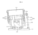
- an exercise machine includes a first clutch (not shown) for intercepting the rotary power transferred from the driver 400 to the first motion unit 200, or a second clutch 336 for intercepting the rotary power transferred to the second motion unit 300.
- the second clutch 336 may be provided at the eccentric wheel 332 of the second transmission unit 330 to intercept the rotary power transferred from the driver 400. Therefore, the second clutch 336 allows the second transmission unit 330 to be connected to a gear assembly, such as a gear train or gear box, to provide different gear ratios, or to fix the second transmission unit 330 by intercepting the rotary power, thereby changing or stopping a motion of the second motion main body 310.
- the first clutch (not shown) may be provided in the rotation shaft 232 of the first transmission unit 230, thereby changing or stopping a motion of the first motion main body 210.
- the exercise machine provides the following effects.
- Fourth, both a pivotal reciprocating motion and a translational reciprocating motion can be performed using a four-bar linkage.
Abstract
Description
- The present invention relates to an exercise machine, and more particularly, to an exercise machine which performs translational reciprocating motions and pivotal reciprocating motions in plural directions.
- These days, many people are interested in health care, health maintenance, and health promotion. In addition, many people receive a diagnosis or advice of a doctor, in medical facilities such as hospitals, for the purpose of early detection or prevention of a disease, and these people often seek health care, health maintenance, or health promotion using non-medical facilities such as a sports club.
- Further, exercise machines, for example, a running machine, a stepping device, and an indoor bicycle, for maintaining or promoting one's health and physical strength are widely used.
US6964614 discloses an exercise machine comprising a support defining a longitudinal direction and a transverse direction; a first motion unit coupled to the support to provide a pivotal movement of the first motion unit in the transverse direction; a second motion unit coupled to the first motion unit to provide one of a translational movement and a pivotal movement of the second motion unit in the longitudinal direction; and a driver configured to impart movement to the first motion unit and the second motion unit. - The present invention has been made in an effort to solve the above problems, and the present invention provides an exercise machine for performing a translational reciprocating motion and a pivotal reciprocating motion using a translational reciprocating motion direction as a rotation axis.
- The present invention further provides an exercise machine for performing a pivotal reciprocating motion in which the rotation axis changes.
- An embodiment of the invention further provides an exercise machine that can change or stop a motion using a clutch.
- The object of the present invention is not limited to the above-described objects and the other objects will be clearly understood by those skilled in the art from the following description.
- According to the present invention, there is provided an exercise machine including a support defining a longitudinal direction and a transverse direction, a first motion unit coupled to the support to provide a combined translational and pivotal movement of the first motion unit in the transverse direction, a second motion unit coupled to the first motion unit to provide one of a translational movement and a pivotal movement of the second motion unit in the longitudinal direction, and a driving source configured to impart movement to the first and second motion units.
- The first motion unit may include a first main body, and a pair of linkage arms connecting the first main body to the support, the combination of the pair of linkage arms, the first main body, and the support form a four-bar linkage.
- Further scope of applicability of the present application will become more apparent from the detailed description given hereinafter. However, it should be understood that the detailed description and specific examples, while indicating preferred embodiments of the invention, are given by way of illustration only, since various changes and modifications within the scope of the invention will become apparent to those skilled in the art from the detailed description.
- The present invention will become more fully understood from the detailed description given hereinbelow and the accompanying drawings, which are provided for illustration purposes only, and thus are not limitative of the present invention, and wherein:
-
FIG. 1 shows a right front perspective view of an exercise machine according to an exemplary embodiment of the present invention; -
FIG. 2 shows a cross-sectional view of the exercise machine ofFIG. 1 ; -
FIGS. 3 and4 show front views demonstrating the operation of a first motion unit of the exercise machine ofFIG. 1 ; -
FIGS. 5(a) and 5(b) show schematic views of alternative arrangements of a first coupling unit of the exercise machine according to an exemplary embodiment of the present invention: and -
FIG. 6 shows a perspective view of a clutch for an exercise machine according to another exemplary embodiment of the present invention. - These and other objects of the present invention will become more readily apparent from the detailed description given hereinafter together with the attached drawings. However, the present invention is not limited to the detailed description given hereinafter, but can be embodied in various forms. It should be understood that the detailed description and specific examples, while indicating preferred embodiments of the invention, are given by way of illustration only, since various changes and modifications within the scope of the invention as defined in the appended claims will become apparent to those skilled in the art from this detailed description. Therefore, the scope of the invention is defined not by the detailed description of the invention but by the appended claims, and all differences within the scope will be construed as being included in the present invention. Like reference numerals designate like elements throughout the specification.
- Hereinafter, exemplary embodiments according to the present invention will be described in detail with reference to the accompanying drawings.
- Referring to
FIG. 1 , the exercise machine according to the present exemplary embodiment includes asupport 110, afirst motion unit 200 coupled to thesupport 110 to perform combined translational and pivotal reciprocating motions, asecond motion unit 300 coupled to thefirst motion unit 200 to perform at least one of translational and pivotal reciprocating motions, and adriver 400 for driving thefirst motion unit 200 and thesecond motion unit 300. - The
support 110 supports thefirst motion unit 200 and thesecond motion unit 300. It is preferable that thesupport 110 supports the exercise machine at the floor in a way that reduces shaking when thefirst motion unit 200 and thesecond motion unit 300 perform reciprocating motions. Further. thesupport 110 should support the exercise machine to prevent the exercise machine from falling when a person sits at the upper side of thesecond motion unit 300 and the exercise machine is in operation. It is preferable that thesupport 110 has a long foothold to support the exercise machine at the floor. - The
first motion unit 200 is coupled to thesupport 110 to perform translational and pivotal reciprocating motions in a transverse (side-to-side) direction. Thefirst motion unit 200 is coupled to thesupport 110 to perform a pivotal reciprocating motion in which the pivot axis changes in the transverse direction. Thefirst motion unit 200 performs a translational reciprocating motion as the pivot axis of the pivotal reciprocating motion changes. Accordingly, thefirst motion unit 200 performs a combined translational reciprocating motion in the transverse direction and pivotal reciprocating motions in the transverse direction. Further. thefirst motion unit 200 performs a reciprocating motion in a vertical direction. - The
first motion unit 200 includes a first motionmain body 210 provided at the upper side of thesupport 110, afirst transmission unit 230 for transferring the rotary power of thedriver 400 to convert the rotary power to a reciprocating motion, and afirst coupling unit 220 for connecting the first motionmain body 210 to thesupport 110 so that the first motionmain body 210 performs the combined translational and pivotal reciprocating motion in the transverse direction. - The first motion
main body 210 is provided at the upper side of thesupport 110 and forms a main body of thefirst motion unit 200. Thedriver 400 for generating the rotary power is provided within the first motionmain body 210. In the described embodiment, the first motionmain body 210 is pivotally coupled to thefirst transmission unit 230. The first motionmain body 210 performs a pivotal reciprocating motion by being coupled to thefirst coupling unit 220. - The
first transmission unit 230 transfers the rotary power of thedriver 400 and converts the rotary power to a reciprocating motion. In the described embodiment, only asinge transmission unit 230 is provided at the left side or the right side of the first motionmain body 210. Thefirst transmission unit 230 will be described later in detail with reference toFIGS. 3 and4 . - The
first coupling unit 220 connects the first motionmain body 210 to thesupport 110 so that the first motionmain body 210 performs a translational and pivotal reciprocating motion in a transverse direction. Thefirst coupling unit 220 is formed with a plurality of revolute joints and the first motionmain body 210 performs a pivotal reciprocating motion while changing the pivot axis in a transverse direction. - The
first coupling unit 220 allows the first motionmain body 210 to perform a pivotal reciprocating motion as well as a translational reciprocating motion in a transverse direction. Further, thefirst coupling unit 220 allows the first motionmain body 210 to perform a reciprocating motion in a vertical direction. - In the described embodiment the
first coupling unit 220 may be formed as a four-bar linkage or a crossed four-bar linkage. For example, thefirst coupling unit 220 includes a pair of linkage arms, and the combination of the pair of linkage arms, the firstmain body 210, and thesupport 110 forms either a four-bar linkage or a crossed four-bar linkage. While the described embodiment shows thefirst coupling unit 220 at a front of the first motionmain body 210, thefirst coupling unit 220 may be formed at a rear of the first motionmain body 210. Alternatively, twofirst coupling units 220 may be provided, one at the front and the other at the rear of the first motionmain body 210. Thefirst coupling unit 220 will be described later in detail with reference toFIGS. 5(a) and 5(b) . - The
second motion unit 300 performs at least one of a translational and a pivotal reciprocating motion in the longitudinal (front-rear) direction. For convenience, further description of the motion of thesecond motion unit 300 will be referred to as translational and pivotal reciprocating motion, but it is understood that only one of translational and pivotal motion need be provided. Thesecond motion unit 300 includes a second motionmain body 310 provided at the upper side of the first motionmain body 210, asecond coupling unit 320 for coupling thesecond motion unit 300 to the first motionmain body 210 so that the second motionmain body 310 performs a translational and pivotal reciprocating motion, and asecond transmission unit 330 for transferring the rotary power of thedriver 400 to convert the rotary power to a reciprocating motion. - The second motion
main body 310 is provided at the upper side of the first motionmain body 210. is fixedly coupled to thesecond transmission unit 330, and is coupled to the first motionmain body 210 by thesecond coupling unit 320. The second motionmain body 310 performs translational and pivotal reciprocating motion in the longitudinal direction and performs a reciprocating motion in the vertical direction. A seat in which a person can sit is provided at the upper side of the second motionmain body 310. - The
second transmission unit 330 transfers the rotary power of thedriver 400 to convert the rotary power to a reciprocating motion. Thesecond transmission unit 330 includes aneccentric wheel 332 for receiving the rotary power from thedriver 400. and asecond motion shaft 334 having one end rotatably coupled to theeccentric wheel 332 and the other end fixedly coupled to the second motionmain body 310. Thesecond transmission unit 330 is provided in plural numbers and is provided at the left side and the right side of the second motionmain body 310. - The
eccentric wheel 332 receives the rotary power from thedriver 400. Theeccentric wheel 332 is coupled to thedriver 400 by a gear to receive the rotary power and may be coupled to a pulley by a belt to receive the rotary power. Theeccentric wheel 332 is rotatably coupled to one end of thesecond motion shaft 334 to eccentrically rotate, thereby converting a rotation motion to a reciprocating motion. The other end of thesecond motion shaft 334 is fixedly coupled to the second motionmain body 310. As a result, a reciprocating motion of thesecond motion shaft 334 is transferred to the second motionmain body 310 and the second motionmain body 310 performs a reciprocating motion. - The
second coupling unit 320 couples the second motionmain body 310 and the first motionmain body 210 so that the second motionmain body 310 performs a translational and pivotal reciprocating motion in the longitudinal direction. Thesecond coupling unit 320 is formed with a one-bar linkage having one end pivotally coupled to the second motionmain body 310 and the other end pivotally coupled to the first motionmain body 210. Thesecond coupling unit 320 is provided in plural numbers and is provided at the left side and the right side of the second motionmain body 310. - In the described embodiment, the
driver 400 is provided in thefirst motion unit 200 to generate the rotary power, thereby driving thefirst motion unit 200 and/or thesecond motion unit 300. In the present exemplary embodiment, thedriver 400 simultaneously drives thefirst motion unit 200 and thesecond motion unit 300; however, it is understood that thedriver 400 may be provided in plural numbers to drive each of thefirst motion unit 200 and thesecond motion unit 300 independently. The rotary power of thedriver 400 is transferred to each of thefirst motion unit 200 and/or thesecond motion unit 300 and is converted to a reciprocating motion, whereby thefirst motion unit 200 and/or thesecond motion unit 300 perform a translational and a pivotal reciprocating motion. Thedriver 400 includes amotor 410 for generating the rotary power and agear unit 420 for changing a rotation axis direction of the rotary power generated by themotor 410 to an orthogonal direction. - The
motor 410 is provided in the first motionmain body 210 to generate the rotary power. Thegear unit 420 may be formed with a bevel gear or a screw gear to change a rotation axis direction of the rotary power generated by themotor 410 to an orthogonal direction. Thegear unit 420 is coupled to arotation shaft 232 and theeccentric wheel 332 by a gear and transfers the rotary power to each of therotation shaft 232 and theeccentric wheel 332. In the present exemplary embodiment, themotor 410 and thegear unit 420 simultaneously drive thefirst motion unit 200 and thesecond motion unit 300; however, it is understood that themotor 410 and thegear unit 420 may be provided in plural numbers to drive each of thefirst motion unit 200 or thesecond motion unit 300 separately. - As seen in
FIGS. 3 and4 , thefirst transmission unit 230 includes therotation shaft 232 for receiving the rotary power from thedriver 400, aneccentric pin 232a formed at the rotation shaft, and afirst motion shaft 234 having one end pivotally coupled to theeccentric pin 232a of therotation shaft 232 and the other end pivotally coupled to thesupport 110. While therotation shaft 232 of the exemplary embodiment is shown as being coupled to thedriver 400 by a gear to receive the rotary power, it is understood that other means can be used to couple therotation shaft 232 and thedriver 400, such as, for example, by being coupled to a belt by a pulley to receive the rotary power. - The
rotation shaft 232 has theeccentric pin 232a at one end thereof. Because therotation shaft 232 has theeccentric pin 232a, which eccentrically rotates, therotation shaft 232 converts a rotation motion to a reciprocating motion. Theeccentric pin 232a of therotation shaft 232 is pivotally coupled to thefirst motion shaft 234. In particular, one end of thefirst motion shaft 234 is pivotally coupled to theeccentric pin 232a of therotation shaft 232 by a universal joint. The other end of thefirst motion shaft 234 is pivotally coupled to thesupport 110 by a universal joint. It is understood that other joints that allow for pivoting motion can be used in place of the universal joints. - When the
rotation shaft 232 receives the rotary power from thedriver 400, theeccentric pin 232a eccentrically rotates. Because thefirst motion shaft 234 is pivotally connected to both theeccentric pin 232a and thesupport 110, thefirst motion shaft 234 converts the rotary power from theeccentric pin 232a to a reciprocating motion. Therefore, the first motionmain body 210 performs a reciprocating motion. - The first motion
main body 210 is coupled to thesupport 110 by thefirst coupling unit 220. Thefirst coupling unit 220 includes a pair of linkage arms, and the combination of the pair of linkage arms, the firstmain body 210, and thesupport 110 form a four-bar linkage. In this exemplary embodiment, the four-bar linkage is a crossed four-bar linkage to allow the first motionmain body 210 to perform a translational and pivotal reciprocating motion in a transverse direction. - As seen in
FIG. 5(a) and 5(b) , thefirst coupling unit 220, in combination with the firstmain body 210, and thesupport 110 may form either a crossed-fourbar linkage 220A (FIG. 5(a) ) or a fourbar linkage 220B (FIG. 5(b) ). The crossed four-bar linkage 220A performs a large pivotal reciprocating motion and a small translational reciprocating motion while the four-bar linkage 220B performs a small pivotal reciprocating motion and a large translational reciprocating motion. Accordingly, it is understood that the crossed four-bar linkage 220A can be used to increase a pivotal reciprocating motion of the first motionmain body 210 and the four-bar linkage 220B can be used to increase a translational reciprocating motion of the first motionmain body 210. - The exercise machine according to the present invention having the above-described configuration operates as follows. When the
motor 410 of thedriver 400 rotates, thegear unit 420 changes a rotation axis direction of the rotary power generated by themotor 410 to an orthogonal direction and transfers the rotary power to each of therotation shaft 232 and theeccentric wheel 332. Next, therotation shaft 232 receives the rotary power from thegear unit 420, thereby causing theeccentric pin 232a of therotation shaft 232 to eccentrically rotate. Thefirst motion shaft 234 coupled to theeccentric pin 232a of therotation shaft 232 by an universal joint performs a reciprocating motion as theeccentric pin 232a eccentrically rotates. Because thefirst motion shaft 234 is coupled to thesupport 110 by an universal joint and the first motionmain body 210 is coupled to thesupport 110 by thefirst coupling unit 220, which forms a crossed four-bar linkage, the first motionmain body 210 performs a translational and pivotal reciprocating motion in a transverse direction when thefirst motion shaft 234 performs a reciprocating motion. - At the same time that the
first motion shaft 234 is reciprocating, theeccentric wheel 332 receives the rotary power from thegear unit 420 to eccentrically rotate. Thesecond motion shaft 334 is pivotally coupled to theeccentric wheel 332 to convert a rotation motion to a reciprocating motion. Because thesecond motion shaft 334 is fixedly coupled to the second motionmain body 310, and the second motionmain body 310 is coupled to the first motionmain body 210 by thesecond coupling unit 320, which is a one-bar linkage, the second motionmain body 310 performs a pivotal reciprocating motion in the longitudinal direction. The effect of the combined motions of thefirst motion unit 200 and the second motion unit is to provide both roll and pitch movements to a ride. It is understood that if the support is set at an angle with respect to a horizontal plane, that a portion of the pitch movement will converted to a yaw motion. - As seen in
FIG. 6 , an exercise machine according to another exemplary embodiment includes a first clutch (not shown) for intercepting the rotary power transferred from thedriver 400 to thefirst motion unit 200, or asecond clutch 336 for intercepting the rotary power transferred to thesecond motion unit 300. With reference toFIG. 4 , thesecond clutch 336 may be provided at theeccentric wheel 332 of thesecond transmission unit 330 to intercept the rotary power transferred from thedriver 400. Therefore, thesecond clutch 336 allows thesecond transmission unit 330 to be connected to a gear assembly, such as a gear train or gear box, to provide different gear ratios, or to fix thesecond transmission unit 330 by intercepting the rotary power, thereby changing or stopping a motion of the second motionmain body 310. Similarly, the first clutch (not shown) may be provided in therotation shaft 232 of thefirst transmission unit 230, thereby changing or stopping a motion of the first motionmain body 210. - The exercise machine according to the present invention provides the following effects. First, a translational reciprocating motion and a pivotal reciprocating motion using a translational reciprocating motion direction as a rotation axis can be performed. Second, a pivotal reciprocating motion in which the rotation axis changes can be performed. Third, a motion can be changed or stopped using a clutch. Fourth, both a pivotal reciprocating motion and a translational reciprocating motion can be performed using a four-bar linkage.
- The effect of the present invention is not limited to the above-described effects and the other effects will be clearly understood by those skilled in the art from the claims.
Claims (15)
- An exercise machine comprising:a support (110) defining a longitudinal direction and a transverse direction;a first motion unit (200) coupled to the support (110) to provide a pivotal movement of the first motion unit (200) in the transverse direction;a second motion unit (300) coupled to the first motion unit (200) to provide one of a translational movement and a pivotal movement of the second motion unit (300) in the longitudinal direction; anda driver (400) configured to impart movement to the first motion unit (200) and the second motion unit (300), characterised in that the first motion unit (200) provides a combined translation and pivotal movement of the first motion unit (200) in the transverse direction
- The exercise machine of claim 1, wherein the first motion unit (200) includes a first motion main body (210) and a first coupling unit (220) connecting the first motion main body (210) to the support (110).
- The exercise machine of claim 2, wherein the first coupling unit (220) includes a pair of linkage arms, and the combination of the pair of linkage arms, the first motion main body (210), and the support (110) form a four-bar linkage.
- The exercise machine of claim 3, wherein the four-bar linkage is a crossed four-bar linkage.
- The exercise machine of claim 2, 3, or 4, wherein the second motion unit (300) includes a second motion main body (310) and a second coupling unit (320) connecting the second motion main body (310) to the first motion main body (210).
- The exercise machine of claim 5, wherein the second coupling unit (320) is a linkage having a first end pivotally connected to the second motion main body (310) and a second end pivotally connected to the first motion main body (210).
- The exercise machine of any of claims 1 to 6, further comprising a first transmission unit (230) connecting the driver (400) to the first motion unit (200).
- The exercise machine of claim 7, wherein the first transmission unit (230) includes:a rotation shaft (232) receiving power from the driver (400), the rotation shaft (232) including an eccentric pin (232a) projecting from the rotation shaft (232); anda first motion shaft (234) having a first end connected to the eccentric pin (232a) and a second end pivotally connected to the support (110).
- The exercise machine of claim 1 to 6, further comprising a second transmission unit (330) connecting the driver (400) to the second motion unit (300).
- The exercise machine of claim 9, wherein the second transmission unit (330) includes:an eccentric wheel (332) receiving power from the driver (400); anda second motion shaft (334) having a first end pivotally connected to the eccentric wheel (332) and a second end fixedly coupled to the second motion unit (300).
- The exercise machine of claim 1, wherein the driver (400) includes:a motor (410) generating the rotary power; anda gear unit (420) changing a rotation axis direction of the rotary power generated by the motor (410) to an orthogonal direction.
- The exercise machine of claim 1, further comprising a first clutch intercepting power transferred from the driver (400) to the first motion unit (200).
- The exercise machine of claim 1, further comprising a second clutch intercepting power transferred from the driver (400) to the second motion unit (300).
- The exercise machine of claim 2, wherein the first motion main body (210) performs a pivotal reciprocating motion while changing the pivot axis in a transverse direction.
- The exercise machine of claim 2, wherein the first coupling unit (220) is formed with a plurality of revolute joints.
Applications Claiming Priority (1)
| Application Number | Priority Date | Filing Date | Title |
|---|---|---|---|
| KR1020080069675A KR101576458B1 (en) | 2008-07-17 | 2008-07-17 | Exercise machine |
Publications (2)
| Publication Number | Publication Date |
|---|---|
| EP2145657A1 EP2145657A1 (en) | 2010-01-20 |
| EP2145657B1 true EP2145657B1 (en) | 2011-04-27 |
Family
ID=41217751
Family Applications (1)
| Application Number | Title | Priority Date | Filing Date |
|---|---|---|---|
| EP09165763A Active EP2145657B1 (en) | 2008-07-17 | 2009-07-17 | Exercise machine |
Country Status (6)
| Country | Link |
|---|---|
| US (1) | US7850627B2 (en) |
| EP (1) | EP2145657B1 (en) |
| KR (1) | KR101576458B1 (en) |
| AT (1) | ATE506991T1 (en) |
| DE (1) | DE602009001150D1 (en) |
| ES (1) | ES2364545T3 (en) |
Families Citing this family (3)
| Publication number | Priority date | Publication date | Assignee | Title |
|---|---|---|---|---|
| DE112010005434B4 (en) * | 2010-03-31 | 2014-11-06 | Xenarts, Inc. | Physical perception robots capable of generating various 3D waveforms with a trajectory of an atypical curve |
| KR101027373B1 (en) * | 2011-01-25 | 2011-04-11 | 유호근 | Cable support structure for underground power lines |
| CN106584447A (en) * | 2017-02-27 | 2017-04-26 | 江苏金刚文化科技集团股份有限公司 | Criss-cross pull wire mechanism and multi-segment criss-cross pull wire mechanism |
Family Cites Families (23)
| Publication number | Priority date | Publication date | Assignee | Title |
|---|---|---|---|---|
| US5884524A (en) * | 1997-09-30 | 1999-03-23 | Single-Tree Art Industry Co., Ltd. | Multi-directional swinging mechanism |
| US6315673B1 (en) * | 1999-10-05 | 2001-11-13 | Midway Amusement Games Llc | Motion simulator for a video game |
| DE60122324T2 (en) * | 2000-06-07 | 2007-08-30 | Matsushita Electric Works, Ltd., Kadoma | DEVICE FOR TRAINING THE BALANCE |
| GB2363993B (en) * | 2000-06-29 | 2002-11-20 | William Ronald Greenwood | Polo training apparatus |
| US6402626B1 (en) * | 2001-07-09 | 2002-06-11 | William A. Beaty | Bucking machine |
| JP3666486B2 (en) * | 2003-01-17 | 2005-06-29 | 松下電工株式会社 | Balance training equipment |
| JP3666485B2 (en) * | 2003-01-17 | 2005-06-29 | 松下電工株式会社 | Balance training equipment |
| EP1629868A4 (en) * | 2003-05-21 | 2008-08-13 | Matsushita Electric Works Ltd | Leg portion training device |
| KR200337159Y1 (en) | 2003-07-16 | 2003-12-31 | 지용구 | Riding Instrument for Exercises |
| JP4039428B2 (en) | 2004-07-27 | 2008-01-30 | 松下電工株式会社 | Oscillating motion device |
| JP4032431B2 (en) * | 2004-10-01 | 2008-01-16 | 松下電工株式会社 | Oscillating motion device |
| JP4032430B2 (en) * | 2004-10-01 | 2008-01-16 | 松下電工株式会社 | Oscillating motion device |
| US6964614B1 (en) * | 2004-10-26 | 2005-11-15 | Tonic Fitness Technology, Inc. | Riding device |
| US7104927B2 (en) * | 2004-10-26 | 2006-09-12 | Tonic Fitness Technology, Inc. | Riding device |
| US20070179022A1 (en) * | 2006-01-27 | 2007-08-02 | Tsung-Yu Chen | Surfing exercisers |
| TWI278333B (en) * | 2006-03-03 | 2007-04-11 | B Green Technology Co Ltd | Equilibrium training exercise apparatus concurrently possessing slide and vibration and exercise method thereof |
| JP4483815B2 (en) | 2006-03-28 | 2010-06-16 | パナソニック電工株式会社 | Oscillating motion device |
| JP4788487B2 (en) * | 2006-06-15 | 2011-10-05 | パナソニック電工株式会社 | Balance training equipment |
| US7448953B2 (en) * | 2006-08-14 | 2008-11-11 | Chiu-Ku Chen | Structure of a horse riding machine |
| US7670230B2 (en) * | 2006-12-13 | 2010-03-02 | Pet Chent Hsu | Transmission mechanism for balance training apparatus |
| KR100838455B1 (en) | 2007-05-15 | 2008-06-16 | 청호나이스 주식회사 | Exercising apparatus for horseback riding |
| US7458923B1 (en) * | 2007-05-22 | 2008-12-02 | King I Tech Corporation | Riding trainer |
| US20090005186A1 (en) * | 2007-06-26 | 2009-01-01 | Jung-Wen Tseng | Horse-riding simulation device |
-
2008
- 2008-07-17 KR KR1020080069675A patent/KR101576458B1/en active IP Right Grant
-
2009
- 2009-07-16 US US12/504,355 patent/US7850627B2/en not_active Expired - Fee Related
- 2009-07-17 DE DE602009001150T patent/DE602009001150D1/en active Active
- 2009-07-17 ES ES09165763T patent/ES2364545T3/en active Active
- 2009-07-17 EP EP09165763A patent/EP2145657B1/en active Active
- 2009-07-17 AT AT09165763T patent/ATE506991T1/en not_active IP Right Cessation
Also Published As
| Publication number | Publication date |
|---|---|
| KR20100009007A (en) | 2010-01-27 |
| DE602009001150D1 (en) | 2011-06-09 |
| EP2145657A1 (en) | 2010-01-20 |
| US20100016124A1 (en) | 2010-01-21 |
| ATE506991T1 (en) | 2011-05-15 |
| KR101576458B1 (en) | 2015-12-10 |
| ES2364545T3 (en) | 2011-09-06 |
| US7850627B2 (en) | 2010-12-14 |
Similar Documents
| Publication | Publication Date | Title |
|---|---|---|
| JP3988642B2 (en) | Balance training equipment | |
| US10500436B1 (en) | Linkage assemblies for exercise devices | |
| US7455623B2 (en) | Elliptical machine | |
| KR100861156B1 (en) | Balance exercise machine | |
| US6475120B2 (en) | Revolving exercise apparatus | |
| CN105142739A (en) | Exercise apparatus comprising adjustable foot pads and related methods | |
| WO2014137512A1 (en) | Exercise assemblies having foot pedal members | |
| CN104958166B (en) | A kind of four limbs cooperative motion recovery training appliance for recovery | |
| TW201431586A (en) | Elliptical trainer | |
| KR101506278B1 (en) | Neck-peripheral muscle exercise apparatus at home | |
| EP2145657B1 (en) | Exercise machine | |
| KR101230458B1 (en) | Rehabilitation machine device for knee joint | |
| CN107030728A (en) | Multi link formula robot neck controlling organization | |
| CN104958165B (en) | A kind of sitting posture state four limbs recovery training appliance for recovery | |
| JP2006271496A (en) | Massage machine | |
| CN108938323A (en) | A kind of four limbs device for healing and training with movement angle detection | |
| CN205799486U (en) | Robot for rehabilitation of anklebone | |
| JP2008264319A (en) | Exercise assisting apparatus | |
| CN108161883A (en) | A kind of main hand of force feedback remote operating | |
| CN210021028U (en) | Joint surgery postoperative rehabilitation training device | |
| CN106377390B (en) | A kind of link-type foot rehabilitation institution | |
| CN201969269U (en) | Elliptic-movement machine | |
| KR101409899B1 (en) | Exercise machine | |
| CN206436232U (en) | The mechanical exoskeleton device of human body Wearable decompression power-assisted | |
| CN105965484A (en) | Ankle rehabilitation robot |
Legal Events
| Date | Code | Title | Description |
|---|---|---|---|
| PUAI | Public reference made under article 153(3) epc to a published international application that has entered the european phase |
Free format text: ORIGINAL CODE: 0009012 |
|
| 17P | Request for examination filed |
Effective date: 20090812 |
|
| AK | Designated contracting states |
Kind code of ref document: A1 Designated state(s): AT BE BG CH CY CZ DE DK EE ES FI FR GB GR HR HU IE IS IT LI LT LU LV MC MK MT NL NO PL PT RO SE SI SK SM TR |
|
| AX | Request for extension of the european patent |
Extension state: AL BA RS |
|
| RIC1 | Information provided on ipc code assigned before grant |
Ipc: A63B 69/04 20060101AFI20100830BHEP |
|
| GRAP | Despatch of communication of intention to grant a patent |
Free format text: ORIGINAL CODE: EPIDOSNIGR1 |
|
| GRAS | Grant fee paid |
Free format text: ORIGINAL CODE: EPIDOSNIGR3 |
|
| GRAA | (expected) grant |
Free format text: ORIGINAL CODE: 0009210 |
|
| RAP1 | Party data changed (applicant data changed or rights of an application transferred) |
Owner name: LG ELECTRONICS INC. |
|
| AK | Designated contracting states |
Kind code of ref document: B1 Designated state(s): AT BE BG CH CY CZ DE DK EE ES FI FR GB GR HR HU IE IS IT LI LT LU LV MC MK MT NL NO PL PT RO SE SI SK SM TR |
|
| REG | Reference to a national code |
Ref country code: GB Ref legal event code: FG4D |
|
| REG | Reference to a national code |
Ref country code: CH Ref legal event code: EP |
|
| REG | Reference to a national code |
Ref country code: IE Ref legal event code: FG4D |
|
| REF | Corresponds to: |
Ref document number: 602009001150 Country of ref document: DE Date of ref document: 20110609 Kind code of ref document: P |
|
| REG | Reference to a national code |
Ref country code: DE Ref legal event code: R096 Ref document number: 602009001150 Country of ref document: DE Effective date: 20110609 |
|
| REG | Reference to a national code |
Ref country code: NL Ref legal event code: VDEP Effective date: 20110427 |
|
| REG | Reference to a national code |
Ref country code: ES Ref legal event code: FG2A Ref document number: 2364545 Country of ref document: ES Kind code of ref document: T3 Effective date: 20110906 |
|
| LTIE | Lt: invalidation of european patent or patent extension |
Effective date: 20110427 |
|
| PG25 | Lapsed in a contracting state [announced via postgrant information from national office to epo] |
Ref country code: HR Free format text: LAPSE BECAUSE OF FAILURE TO SUBMIT A TRANSLATION OF THE DESCRIPTION OR TO PAY THE FEE WITHIN THE PRESCRIBED TIME-LIMIT Effective date: 20110427 Ref country code: NO Free format text: LAPSE BECAUSE OF FAILURE TO SUBMIT A TRANSLATION OF THE DESCRIPTION OR TO PAY THE FEE WITHIN THE PRESCRIBED TIME-LIMIT Effective date: 20110727 Ref country code: LT Free format text: LAPSE BECAUSE OF FAILURE TO SUBMIT A TRANSLATION OF THE DESCRIPTION OR TO PAY THE FEE WITHIN THE PRESCRIBED TIME-LIMIT Effective date: 20110427 Ref country code: SE Free format text: LAPSE BECAUSE OF FAILURE TO SUBMIT A TRANSLATION OF THE DESCRIPTION OR TO PAY THE FEE WITHIN THE PRESCRIBED TIME-LIMIT Effective date: 20110427 Ref country code: PT Free format text: LAPSE BECAUSE OF FAILURE TO SUBMIT A TRANSLATION OF THE DESCRIPTION OR TO PAY THE FEE WITHIN THE PRESCRIBED TIME-LIMIT Effective date: 20110829 |
|
| PG25 | Lapsed in a contracting state [announced via postgrant information from national office to epo] |
Ref country code: FI Free format text: LAPSE BECAUSE OF FAILURE TO SUBMIT A TRANSLATION OF THE DESCRIPTION OR TO PAY THE FEE WITHIN THE PRESCRIBED TIME-LIMIT Effective date: 20110427 Ref country code: BE Free format text: LAPSE BECAUSE OF FAILURE TO SUBMIT A TRANSLATION OF THE DESCRIPTION OR TO PAY THE FEE WITHIN THE PRESCRIBED TIME-LIMIT Effective date: 20110427 Ref country code: AT Free format text: LAPSE BECAUSE OF FAILURE TO SUBMIT A TRANSLATION OF THE DESCRIPTION OR TO PAY THE FEE WITHIN THE PRESCRIBED TIME-LIMIT Effective date: 20110427 Ref country code: LV Free format text: LAPSE BECAUSE OF FAILURE TO SUBMIT A TRANSLATION OF THE DESCRIPTION OR TO PAY THE FEE WITHIN THE PRESCRIBED TIME-LIMIT Effective date: 20110427 Ref country code: IS Free format text: LAPSE BECAUSE OF FAILURE TO SUBMIT A TRANSLATION OF THE DESCRIPTION OR TO PAY THE FEE WITHIN THE PRESCRIBED TIME-LIMIT Effective date: 20110827 Ref country code: SI Free format text: LAPSE BECAUSE OF FAILURE TO SUBMIT A TRANSLATION OF THE DESCRIPTION OR TO PAY THE FEE WITHIN THE PRESCRIBED TIME-LIMIT Effective date: 20110427 Ref country code: CY Free format text: LAPSE BECAUSE OF FAILURE TO SUBMIT A TRANSLATION OF THE DESCRIPTION OR TO PAY THE FEE WITHIN THE PRESCRIBED TIME-LIMIT Effective date: 20110427 Ref country code: GR Free format text: LAPSE BECAUSE OF FAILURE TO SUBMIT A TRANSLATION OF THE DESCRIPTION OR TO PAY THE FEE WITHIN THE PRESCRIBED TIME-LIMIT Effective date: 20110728 |
|
| PG25 | Lapsed in a contracting state [announced via postgrant information from national office to epo] |
Ref country code: NL Free format text: LAPSE BECAUSE OF FAILURE TO SUBMIT A TRANSLATION OF THE DESCRIPTION OR TO PAY THE FEE WITHIN THE PRESCRIBED TIME-LIMIT Effective date: 20110427 Ref country code: MT Free format text: LAPSE BECAUSE OF FAILURE TO SUBMIT A TRANSLATION OF THE DESCRIPTION OR TO PAY THE FEE WITHIN THE PRESCRIBED TIME-LIMIT Effective date: 20110427 |
|
| PG25 | Lapsed in a contracting state [announced via postgrant information from national office to epo] |
Ref country code: EE Free format text: LAPSE BECAUSE OF FAILURE TO SUBMIT A TRANSLATION OF THE DESCRIPTION OR TO PAY THE FEE WITHIN THE PRESCRIBED TIME-LIMIT Effective date: 20110427 Ref country code: CZ Free format text: LAPSE BECAUSE OF FAILURE TO SUBMIT A TRANSLATION OF THE DESCRIPTION OR TO PAY THE FEE WITHIN THE PRESCRIBED TIME-LIMIT Effective date: 20110427 |
|
| PG25 | Lapsed in a contracting state [announced via postgrant information from national office to epo] |
Ref country code: MC Free format text: LAPSE BECAUSE OF NON-PAYMENT OF DUE FEES Effective date: 20110731 Ref country code: SK Free format text: LAPSE BECAUSE OF FAILURE TO SUBMIT A TRANSLATION OF THE DESCRIPTION OR TO PAY THE FEE WITHIN THE PRESCRIBED TIME-LIMIT Effective date: 20110427 Ref country code: PL Free format text: LAPSE BECAUSE OF FAILURE TO SUBMIT A TRANSLATION OF THE DESCRIPTION OR TO PAY THE FEE WITHIN THE PRESCRIBED TIME-LIMIT Effective date: 20110427 |
|
| PLBE | No opposition filed within time limit |
Free format text: ORIGINAL CODE: 0009261 |
|
| STAA | Information on the status of an ep patent application or granted ep patent |
Free format text: STATUS: NO OPPOSITION FILED WITHIN TIME LIMIT |
|
| 26N | No opposition filed |
Effective date: 20120130 |
|
| REG | Reference to a national code |
Ref country code: IE Ref legal event code: MM4A |
|
| REG | Reference to a national code |
Ref country code: DE Ref legal event code: R097 Ref document number: 602009001150 Country of ref document: DE Effective date: 20120130 |
|
| PG25 | Lapsed in a contracting state [announced via postgrant information from national office to epo] |
Ref country code: IE Free format text: LAPSE BECAUSE OF NON-PAYMENT OF DUE FEES Effective date: 20110717 |
|
| PG25 | Lapsed in a contracting state [announced via postgrant information from national office to epo] |
Ref country code: MK Free format text: LAPSE BECAUSE OF FAILURE TO SUBMIT A TRANSLATION OF THE DESCRIPTION OR TO PAY THE FEE WITHIN THE PRESCRIBED TIME-LIMIT Effective date: 20110427 |
|
| PG25 | Lapsed in a contracting state [announced via postgrant information from national office to epo] |
Ref country code: SM Free format text: LAPSE BECAUSE OF FAILURE TO SUBMIT A TRANSLATION OF THE DESCRIPTION OR TO PAY THE FEE WITHIN THE PRESCRIBED TIME-LIMIT Effective date: 20110427 |
|
| PG25 | Lapsed in a contracting state [announced via postgrant information from national office to epo] |
Ref country code: LU Free format text: LAPSE BECAUSE OF NON-PAYMENT OF DUE FEES Effective date: 20110717 |
|
| PG25 | Lapsed in a contracting state [announced via postgrant information from national office to epo] |
Ref country code: BG Free format text: LAPSE BECAUSE OF FAILURE TO SUBMIT A TRANSLATION OF THE DESCRIPTION OR TO PAY THE FEE WITHIN THE PRESCRIBED TIME-LIMIT Effective date: 20110727 |
|
| PG25 | Lapsed in a contracting state [announced via postgrant information from national office to epo] |
Ref country code: TR Free format text: LAPSE BECAUSE OF FAILURE TO SUBMIT A TRANSLATION OF THE DESCRIPTION OR TO PAY THE FEE WITHIN THE PRESCRIBED TIME-LIMIT Effective date: 20110427 |
|
| PG25 | Lapsed in a contracting state [announced via postgrant information from national office to epo] |
Ref country code: HU Free format text: LAPSE BECAUSE OF FAILURE TO SUBMIT A TRANSLATION OF THE DESCRIPTION OR TO PAY THE FEE WITHIN THE PRESCRIBED TIME-LIMIT Effective date: 20110427 |
|
| REG | Reference to a national code |
Ref country code: CH Ref legal event code: PL |
|
| PG25 | Lapsed in a contracting state [announced via postgrant information from national office to epo] |
Ref country code: CH Free format text: LAPSE BECAUSE OF NON-PAYMENT OF DUE FEES Effective date: 20130731 Ref country code: LI Free format text: LAPSE BECAUSE OF NON-PAYMENT OF DUE FEES Effective date: 20130731 |
|
| PGFP | Annual fee paid to national office [announced via postgrant information from national office to epo] |
Ref country code: GB Payment date: 20140611 Year of fee payment: 6 |
|
| PGFP | Annual fee paid to national office [announced via postgrant information from national office to epo] |
Ref country code: ES Payment date: 20140613 Year of fee payment: 6 |
|
| PGFP | Annual fee paid to national office [announced via postgrant information from national office to epo] |
Ref country code: DE Payment date: 20140611 Year of fee payment: 6 |
|
| PGFP | Annual fee paid to national office [announced via postgrant information from national office to epo] |
Ref country code: FR Payment date: 20140611 Year of fee payment: 6 |
|
| PGFP | Annual fee paid to national office [announced via postgrant information from national office to epo] |
Ref country code: IT Payment date: 20140716 Year of fee payment: 6 |
|
| REG | Reference to a national code |
Ref country code: DE Ref legal event code: R119 Ref document number: 602009001150 Country of ref document: DE |
|
| GBPC | Gb: european patent ceased through non-payment of renewal fee |
Effective date: 20150717 |
|
| PG25 | Lapsed in a contracting state [announced via postgrant information from national office to epo] |
Ref country code: GB Free format text: LAPSE BECAUSE OF NON-PAYMENT OF DUE FEES Effective date: 20150717 Ref country code: IT Free format text: LAPSE BECAUSE OF NON-PAYMENT OF DUE FEES Effective date: 20150717 Ref country code: DE Free format text: LAPSE BECAUSE OF NON-PAYMENT OF DUE FEES Effective date: 20160202 |
|
| REG | Reference to a national code |
Ref country code: FR Ref legal event code: ST Effective date: 20160331 |
|
| PG25 | Lapsed in a contracting state [announced via postgrant information from national office to epo] |
Ref country code: FR Free format text: LAPSE BECAUSE OF NON-PAYMENT OF DUE FEES Effective date: 20150731 |
|
| REG | Reference to a national code |
Ref country code: ES Ref legal event code: FD2A Effective date: 20160826 |
|
| PG25 | Lapsed in a contracting state [announced via postgrant information from national office to epo] |
Ref country code: ES Free format text: LAPSE BECAUSE OF NON-PAYMENT OF DUE FEES Effective date: 20150718 |