EP2145526A2 - Center conveyor front coupler for a draper cutting platform - Google Patents
Center conveyor front coupler for a draper cutting platform Download PDFInfo
- Publication number
- EP2145526A2 EP2145526A2 EP09164646A EP09164646A EP2145526A2 EP 2145526 A2 EP2145526 A2 EP 2145526A2 EP 09164646 A EP09164646 A EP 09164646A EP 09164646 A EP09164646 A EP 09164646A EP 2145526 A2 EP2145526 A2 EP 2145526A2
- Authority
- EP
- European Patent Office
- Prior art keywords
- center
- platform
- cutting platform
- draper
- platform section
- Prior art date
- Legal status (The legal status is an assumption and is not a legal conclusion. Google has not performed a legal analysis and makes no representation as to the accuracy of the status listed.)
- Granted
Links
- 230000013011 mating Effects 0.000 claims abstract description 12
- 239000000463 material Substances 0.000 description 20
- 235000013339 cereals Nutrition 0.000 description 13
- 238000000034 method Methods 0.000 description 4
- 230000007246 mechanism Effects 0.000 description 2
- 230000032258 transport Effects 0.000 description 2
- 244000068988 Glycine max Species 0.000 description 1
- 235000010469 Glycine max Nutrition 0.000 description 1
- 241001124569 Lycaenidae Species 0.000 description 1
- 241000209140 Triticum Species 0.000 description 1
- 235000021307 Triticum Nutrition 0.000 description 1
- 238000006243 chemical reaction Methods 0.000 description 1
- 230000001419 dependent effect Effects 0.000 description 1
- 230000009977 dual effect Effects 0.000 description 1
- 238000003306 harvesting Methods 0.000 description 1
- 239000002184 metal Substances 0.000 description 1
Images


Classifications
-
- A—HUMAN NECESSITIES
- A01—AGRICULTURE; FORESTRY; ANIMAL HUSBANDRY; HUNTING; TRAPPING; FISHING
- A01D—HARVESTING; MOWING
- A01D57/00—Delivering mechanisms for harvesters or mowers
- A01D57/20—Delivering mechanisms for harvesters or mowers with conveyor belts
-
- A—HUMAN NECESSITIES
- A01—AGRICULTURE; FORESTRY; ANIMAL HUSBANDRY; HUNTING; TRAPPING; FISHING
- A01D—HARVESTING; MOWING
- A01D41/00—Combines, i.e. harvesters or mowers combined with threshing devices
- A01D41/12—Details of combines
- A01D41/14—Mowing tables
- A01D41/16—Devices for coupling mowing tables to conveyors
-
- A—HUMAN NECESSITIES
- A01—AGRICULTURE; FORESTRY; ANIMAL HUSBANDRY; HUNTING; TRAPPING; FISHING
- A01D—HARVESTING; MOWING
- A01D61/00—Elevators or conveyors for binders or combines
- A01D61/002—Elevators or conveyors for binders or combines transversal conveying devices
-
- Y—GENERAL TAGGING OF NEW TECHNOLOGICAL DEVELOPMENTS; GENERAL TAGGING OF CROSS-SECTIONAL TECHNOLOGIES SPANNING OVER SEVERAL SECTIONS OF THE IPC; TECHNICAL SUBJECTS COVERED BY FORMER USPC CROSS-REFERENCE ART COLLECTIONS [XRACs] AND DIGESTS
- Y10—TECHNICAL SUBJECTS COVERED BY FORMER USPC
- Y10T—TECHNICAL SUBJECTS COVERED BY FORMER US CLASSIFICATION
- Y10T29/00—Metal working
- Y10T29/49—Method of mechanical manufacture
- Y10T29/49826—Assembling or joining
- Y10T29/49895—Associating parts by use of aligning means [e.g., use of a drift pin or a "fixture"]
Definitions
- the present invention relates to agricultural harvesters, and, more particularly, to agricultural combines including a draper cutting platform.
- An agricultural harvester such as a combine includes a head and a feeder housing which remove the crop material from the field, gather the crop material and transport the crop material to a separator.
- the head In the case of thinner stemmed crops such as soybeans, wheat, etc. which may be cut with a sickle bar carrying a plurality of knives, the head may also be known as a cutting platform.
- the separator removes the grain crop material from the non-grain crop material.
- the grain is cleaned and deposited in a grain tank.
- an unloading auger which is positioned alongside the combine during harvesting is moved to the unloading position in which the auger extends approximately perpendicular to the longitudinal axis of the combine.
- the combine drives alongside a vehicle into which the grain is to be unloaded, such as a semi-trailer, and the unloading auger is actuated to discharge the grain into the vehicle.
- a cutting platform may generally be of two types.
- One type typically has a sheet metal floor with a dual feed auger near the rear of the cutting platform for feeding the crop material longitudinally to the feeder housing.
- a cutting platform of this type with auger feed is more common.
- FIG. 1 Another type of cutting platform, also known as a draper platform, utilizes a flat, wide belt, referred to as a draper or draper belt to convey crop material.
- the arrangement and number of belts vary among platforms.
- One style of draper platform has two side belts that convey crop material longitudinally, to the center of the platform, where a center belt moves the crop material laterally into the feeder housing.
- Each belt is wrapped around a pair of rollers, one being a drive roller and the other being an idler roller.
- An example of this type draper arrangement is disclosed in US 6 202 397 B .
- An advantage of a draper platform is that larger amounts of crop material can be transported without plugging, etc. For example, with wide platforms approaching 40 feet or even larger, the amount of crop material transported to the feeder housing can be substantial. With an auger feed platform, the crop material may bind between the auger and the back wall of the platform. In contrast, with a draper platform, the crop material is carried on top of the belt with less chance for plugging.
- a draper platform which may be operated either as a harvester or a swather.
- the center section in front of the feederhousing which carries the center belt is in place between the side sections.
- the center section is removed from the draper cutting platform. This allows the crop material from each side section to be deposited in the open area between the side sections, forming a windrow as the swather moves forward.
- a problem with a removable center section on a draper platform is that it is difficult and time consuming to align and attach the center section to the frame and cutterbar assembly. This process typically takes multiple personnel to accomplish, and results in a loss in productivity.
- the invention in one form is directed to a draper cutting platform for use with an agricultural harvester.
- the cutting platform includes a pair of side platform sections, with each side platform section including a side belt.
- a center platform section is disposed in an area between the side platform sections.
- the center platform section includes at least one alignment device and at least one latch.
- a center conveyor assembly is removably attached to the center platform section, and carries a center belt.
- the center conveyor assembly includes at least one mating alignment device and at least one mating latch.
- the invention in another form is directed to an agricultural harvester, including a feeder housing and a cutting platform.
- the cutting platform includes a pair of side platform sections, with each side platform section having a side belt.
- a center platform section is disposed in an area between the side platform sections, and includes at least one alignment device and at least one latch.
- a center conveyor assembly is attached to the feeder housing and removably attached to the center platform section.
- the center conveyor assembly carries a center belt, and includes at least one mating alignment device and at least one mating latch.
- the invention in yet another form is directed to a method of attaching a center conveyor assembly to a center platform section of a draper cutting platform, including the steps of: positioning a base unit of an agricultural harvester such that a center conveyor assembly mounted to the front of the base unit is in general alignment with a center platform section of the cutting platform; moving the base unit forward until at least one alignment device mounted to the center platform section engages with a corresponding at least one mating alignment device mounted to the center conveyor assembly; and latching the center conveyor assembly to the center platform section.
- Combine 10 includes a feeder housing 14 which is detachably coupled with cutting platform 12.
- Feeder housing 14 receives the crop material from cutting platform 12, both grain and non-grain crop material, and transports the crop material to a separator within combine 10 in known manner (not shown).
- the grain crop material is separated from the non-grain crop material, cleaned and transported to a grain tank.
- the non-grain crop material is transported to a chopper, blower, etc. in known manner and distributed back to the field.
- Cutting platform 12 generally includes a plurality of platform sections 16, 18 and 20, a cutterbar assembly 22 and a reel assembly 24.
- platform section 16 is a center platform section
- platform section 18 is a first side platform section
- platform section 20 is a second side platform section.
- First side platform section 18 and second side platform section 20 are each configured as partially foldable wing sections in the illustrated embodiment, and thus may be referred to as wing platform sections hereinafter. It will be appreciated, however, that side platform sections 18 and 20 need not be partially foldable. Further, although shown with three platform sections, cutting platform 12 may be configured with more or less platform sections, depending upon the particular application.
- Each platform section 16, 18 and 20 generally includes a frame 26, a plurality of float arms 28 coupled with a respective frame 26, a cutterbar assembly 22 carried by the outboard ends of respective float arms 28, and at least one endless belt 32 ( Fig. 2 ).
- the frame 26 of first wing platform section 18 and second wing platform section 20 are each pivotally coupled with center platform section 16, such that the outboard ends of first wing platform section 18 and second wing platform section 20 can move up and down independent from center platform section 16.
- a lift cylinder 36 coupled between the frame of combine 10 and feeder housing 14 lifts the entire cutting platform 12
- a first tilt cylinder 38 coupled between the respective frame 26 of first wing platform section 18 and center platform section 16 pivotally moves first wing platform section 18 relative to center platform section 16
- a second tilt cylinder 40 coupled between the respective frame 26 of second wing platform section 20 and center platform section 16 pivotally moves second wing platform section 20 relative to center platform section 16.
- Reel assembly 24 includes two reels 56, center reel support arm 58 and a pair of outer reel support arms 60.
- Outer reel support arms 60 are pivotally coupled at one end thereof with an outboard end of a respective first wing platform section 18 or second wing platform section 20.
- Outer reel support arms 60 rotationally carry a respective reel 56 at an opposite end thereof.
- Each outer reel support arm 60 may be selectively moved up and down using a hydraulic cylinder, and the pair of hydraulic cylinders are typically coupled in parallel so that they move together upon actuation.
- Center reel support arm 58 is pivotally coupled at one end thereof with center platform section 16 above the opening leading to feeder housing 14.
- Center reel support arm 58 rotationally carries an inboard end of each reel 56 at an opposite end thereof.
- a hydraulic motor 62 or other suitable mechanical drive rotationally drives each reel 56. More particularly, hydraulic motor 62 drives a common drive shaft 64 through a chain and sprocket or other suitable arrangement (not shown). The rotational speed of reels 56 can be adjusted by an operator by adjusting the rotational speed of hydraulic motor 62.
- Center reel support arm 58 may be selectively moved up and down using a hydraulic cylinder 66. Center reel support arm 58 is movable independently from outer reel support arms 60. To accommodate this independent movement, drive shaft 64 driven by hydraulic motor 62 is coupled at each end thereof via a universal joint 68 with a respective reel 56. This independent movement of center reel support arm 58 can be accomplished manually using a separate actuating switch or lever in operator's cab 70, or automatically using an electronic controller 72 located within cab 70 or other suitable location.
- center platform section 16 includes a removable center conveyor assembly 70 which is positioned between the pair of side belts (one of which is shown and labeled 32B) carried by respective side platform sections 18 and 20.
- Each side platform section 18 and 20 carries cutterbar assembly 22, which also spans across center platform section 16.
- Center conveyor assembly 70 includes a sub-frame 72 which carries at least a pair of rollers (not specifically shown), which in turn carry a center belt 32A.
- the rear end 74 of center conveyor assembly 70 is coupled with a feeder drum 76 positioned at the front of feeder housing 14.
- the front or leading edge 78 of center conveyor assembly 70 carries at least one alignment device 80 which mates with a corresponding alignment device 82 carried by center platform section 16.
- center platform section 16 includes at least one alignment device 82 in the form of a pair of vertical alignment guides.
- Each vertical alignment guide 82 has a generally triangular shape when viewed from the side, and includes a top flange 84, a spaced apart diverging bottom flange 86, and a seat 88 at an apex between top and bottom flanges 84 and 86.
- Bottom flange 86 defines an upwardly sloped ramp which guides the alignment device 80 at the leading edge of center conveyor assembly 70.
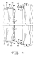
- Each vertical alignment guide 82 is also slightly laterally flared (see Fig. 4 ) which assists in side to side alignment between center conveyor assembly 70 and center platform section 16.
- Vertical alignment guide 82 also includes a latch hole 90 which extends through a side wall of vertical alignment guide 82 at a position adjacent to seat 88, and defines an axis of rotation 92 about which vertical alignment guide 82 may pivot through a fixed angular range.
- Figs. 5 and 6 show the vertical alignment guide 82 when positioned at a downward angle of about 20 degrees prior to connection with alignment device 80, and Figs. 7 and 8 show the vertical alignment guide 82 when rotated upward upon seating of alignment device 80.
- the at least one alignment device 80 includes a pair of guide pins 94 and corresponding guide plates 96.
- Each guide pin 94 extends laterally from a respective forward, lateral edge 78 of center conveyor assembly 70.
- Guide pins 94 have an outside diameter which is sized to seat within a corresponding seat 88 of a vertical alignment guide 82.
- Each guide plate 96 extends rearwardly and generally tangent from a top edge of a corresponding guide pin 94.
- Guide plates 96 engage top flange 84 of a respective vertical alignment guide 82 and rotate vertical alignment guides 82 to the upper position shown in Figs. 7 and 8 when guide pin 94 is fully seated in seat 88.
- a pair of latch pins 98 are slidably disposed in a bore (not numbered) formed in a respective guide pin 94. Each latch pin 98 passes through a respective guide pin 94 and extends into a respective latch hole 90. Latch pins 98 are preferably spring biased ( Fig. 5-7 ) into a respective latch hole 90 when guide pin 94 is in the seated position in seat 88.
- each lock 100 includes a spring biased pin 102 which engages with a recess 104 formed in a corresponding vertical alignment guide 82.
- Fig. 8 shows pin 102 in the unlocked position
- Fig. 9 shows pin 102 in the locked position.
- Pin 102 is spring biased (see, e.g., Fig. 5 ) and can be manually moved from the locked to the unlocked position, or vice versa.
- alignment guide 80 includes a guide pin 94 and a guide plate 96.
- vertical alignment guide 82 includes a top flange 84, bottom flange 86 and seat 88. It is possible, however, that a different type of alignment arrangement can be provided between center conveyor assembly 70 and center platform section 16. For example, it could be possible that the leading edge of center conveyor assembly 70 can have a generally U-shaped nose extending across its width which fits into a corresponding U-shaped recess positioned behind the cutterbar assembly 22. Further, it is possible that the latching mechanisms for latching center conveyor assembly 70 to center platform section 16 can be of a different form. Additionally, it is possible that the locking mechanisms for locking the angular orientation of vertical alignment guide 82 can be of a different form.
- the base unit of agricultural harvester 10 is positioned such that center conveyor assembly 70 mounted to the front of the base unit is in general alignment with center platform section 16 ( Fig. 3 ).
- the base unit is moved forward (as indicated by arrow 106) until each vertical alignment guide 82 mounted to center platform section 16 engages with a corresponding alignment device 80 mounted to center conveyor assembly 70.
- each spring biased latch pin 98 latches within a corresponding latch hole 90 to latch center conveyor assembly 70 to center platform section 16 ( Figs. 7 and 8 ).
- latch pins 102 may be manually pulled, rotated and locked in place within a corresponding recess 104 to lock the vertical alignment guide 82 in the up position.
- the procedure can be simply reversed.
Abstract
Description
- The present invention relates to agricultural harvesters, and, more particularly, to agricultural combines including a draper cutting platform.
- An agricultural harvester such as a combine includes a head and a feeder housing which remove the crop material from the field, gather the crop material and transport the crop material to a separator. In the case of thinner stemmed crops such as soybeans, wheat, etc. which may be cut with a sickle bar carrying a plurality of knives, the head may also be known as a cutting platform. The separator removes the grain crop material from the non-grain crop material. The grain is cleaned and deposited in a grain tank. When the grain tank becomes full, an unloading auger which is positioned alongside the combine during harvesting is moved to the unloading position in which the auger extends approximately perpendicular to the longitudinal axis of the combine. The combine drives alongside a vehicle into which the grain is to be unloaded, such as a semi-trailer, and the unloading auger is actuated to discharge the grain into the vehicle.
- A cutting platform may generally be of two types. One type typically has a sheet metal floor with a dual feed auger near the rear of the cutting platform for feeding the crop material longitudinally to the feeder housing. A cutting platform of this type with auger feed is more common.
- Another type of cutting platform, also known as a draper platform, utilizes a flat, wide belt, referred to as a draper or draper belt to convey crop material. The arrangement and number of belts vary among platforms. One style of draper platform has two side belts that convey crop material longitudinally, to the center of the platform, where a center belt moves the crop material laterally into the feeder housing. Each belt is wrapped around a pair of rollers, one being a drive roller and the other being an idler roller. An example of this type draper arrangement is disclosed in
US 6 202 397 B . - An advantage of a draper platform is that larger amounts of crop material can be transported without plugging, etc. For example, with wide platforms approaching 40 feet or even larger, the amount of crop material transported to the feeder housing can be substantial. With an auger feed platform, the crop material may bind between the auger and the back wall of the platform. In contrast, with a draper platform, the crop material is carried on top of the belt with less chance for plugging.
- With a draper platform as described above, it is known to have a draper platform which may be operated either as a harvester or a swather. When configured as a harvester, the center section in front of the feederhousing which carries the center belt is in place between the side sections. When configured as a swather, the center section is removed from the draper cutting platform. This allows the crop material from each side section to be deposited in the open area between the side sections, forming a windrow as the swather moves forward.
- A problem with a removable center section on a draper platform is that it is difficult and time consuming to align and attach the center section to the frame and cutterbar assembly. This process typically takes multiple personnel to accomplish, and results in a loss in productivity.
- What is needed in the art is a draper cutting platform which may be operated either as a harvester or a swather, with simple and fast conversion between the two.
- This object is achieved with the subject matter of claim 1. The dependent claims recite advantageous embodiments of the invention.
- The invention in one form is directed to a draper cutting platform for use with an agricultural harvester. The cutting platform includes a pair of side platform sections, with each side platform section including a side belt. A center platform section is disposed in an area between the side platform sections. The center platform section includes at least one alignment device and at least one latch. A center conveyor assembly is removably attached to the center platform section, and carries a center belt. The center conveyor assembly includes at least one mating alignment device and at least one mating latch.
- The invention in another form is directed to an agricultural harvester, including a feeder housing and a cutting platform. The cutting platform includes a pair of side platform sections, with each side platform section having a side belt. A center platform section is disposed in an area between the side platform sections, and includes at least one alignment device and at least one latch. A center conveyor assembly is attached to the feeder housing and removably attached to the center platform section. The center conveyor assembly carries a center belt, and includes at least one mating alignment device and at least one mating latch.
- The invention in yet another form is directed to a method of attaching a center conveyor assembly to a center platform section of a draper cutting platform, including the steps of: positioning a base unit of an agricultural harvester such that a center conveyor assembly mounted to the front of the base unit is in general alignment with a center platform section of the cutting platform; moving the base unit forward until at least one alignment device mounted to the center platform section engages with a corresponding at least one mating alignment device mounted to the center conveyor assembly; and latching the center conveyor assembly to the center platform section.
- An embodiment of the invention is shown in the drawings, in which:
-
Fig. 1 is a fragmentary, top view of an agricultural combine including an embodiment of a draper platform of the present invention; -
Fig. 2 is a fragmentary, perspective view of the agricultural combine ofFig. 1 ; -
Fig. 3 is a fragmentary, perspective view of the center conveyor assembly positioned relative to the center platform section; -
Fig. 4 is a top, fragmentary view of the center conveyor assembly and center platform section shown inFig. 3 ; -
Fig. 5 is a fragmentary, perspective, partially phantom view of the center conveyor assembly and center platform section shown inFigs. 3 and4 ; -
Fig. 6 is another fragmentary, perspective, partially phantom view of the center conveyor assembly and center platform section shown inFigs. 3-5 ; -
Fig. 7 is yet another fragmentary, perspective, partially phantom view of the center conveyor assembly and center platform section shown inFigs. 3-6 ; -
Fig. 8 is a side view illustrating the alignment device of the center conveyor assembly in a seated position within the vertical alignment guide of the center platform section; and -
Fig. 9 is a perspective view of the vertical alignment guide in a locked position. - Referring now to the drawings, and, more particularly to
Figs. 1 and2 , there is shown an agricultural harvester in the form of acombine 10 including an embodiment of acutting platform 12 of the present invention. Combine 10 includes afeeder housing 14 which is detachably coupled withcutting platform 12.Feeder housing 14 receives the crop material from cuttingplatform 12, both grain and non-grain crop material, and transports the crop material to a separator within combine 10 in known manner (not shown). The grain crop material is separated from the non-grain crop material, cleaned and transported to a grain tank. The non-grain crop material is transported to a chopper, blower, etc. in known manner and distributed back to the field. -
Cutting platform 12 generally includes a plurality ofplatform sections cutterbar assembly 22 and areel assembly 24. In the embodiment shown,platform section 16 is a center platform section,platform section 18 is a first side platform section, andplatform section 20 is a second side platform section. Firstside platform section 18 and secondside platform section 20 are each configured as partially foldable wing sections in the illustrated embodiment, and thus may be referred to as wing platform sections hereinafter. It will be appreciated, however, thatside platform sections cutting platform 12 may be configured with more or less platform sections, depending upon the particular application. - Each
platform section frame 26, a plurality offloat arms 28 coupled with arespective frame 26, acutterbar assembly 22 carried by the outboard ends ofrespective float arms 28, and at least one endless belt 32 (Fig. 2 ). Theframe 26 of firstwing platform section 18 and secondwing platform section 20 are each pivotally coupled withcenter platform section 16, such that the outboard ends of firstwing platform section 18 and secondwing platform section 20 can move up and down independent fromcenter platform section 16. To that end, alift cylinder 36 coupled between the frame ofcombine 10 andfeeder housing 14 lifts theentire cutting platform 12, afirst tilt cylinder 38 coupled between therespective frame 26 of firstwing platform section 18 andcenter platform section 16 pivotally moves firstwing platform section 18 relative tocenter platform section 16, and asecond tilt cylinder 40 coupled between therespective frame 26 of secondwing platform section 20 andcenter platform section 16 pivotally moves secondwing platform section 20 relative tocenter platform section 16. -
Reel assembly 24 includes tworeels 56, centerreel support arm 58 and a pair of outerreel support arms 60. Outerreel support arms 60 are pivotally coupled at one end thereof with an outboard end of a respective firstwing platform section 18 or secondwing platform section 20. Outerreel support arms 60 rotationally carry arespective reel 56 at an opposite end thereof. Each outerreel support arm 60 may be selectively moved up and down using a hydraulic cylinder, and the pair of hydraulic cylinders are typically coupled in parallel so that they move together upon actuation. - Center
reel support arm 58 is pivotally coupled at one end thereof withcenter platform section 16 above the opening leading tofeeder housing 14. Centerreel support arm 58 rotationally carries an inboard end of eachreel 56 at an opposite end thereof. Ahydraulic motor 62 or other suitable mechanical drive rotationally drives eachreel 56. More particularly,hydraulic motor 62 drives acommon drive shaft 64 through a chain and sprocket or other suitable arrangement (not shown). The rotational speed ofreels 56 can be adjusted by an operator by adjusting the rotational speed ofhydraulic motor 62. - Center
reel support arm 58 may be selectively moved up and down using ahydraulic cylinder 66. Centerreel support arm 58 is movable independently from outerreel support arms 60. To accommodate this independent movement, driveshaft 64 driven byhydraulic motor 62 is coupled at each end thereof via a universal joint 68 with arespective reel 56. This independent movement of centerreel support arm 58 can be accomplished manually using a separate actuating switch or lever in operator'scab 70, or automatically using anelectronic controller 72 located withincab 70 or other suitable location. - Referring to
Fig. 3 ,center platform section 16 includes a removablecenter conveyor assembly 70 which is positioned between the pair of side belts (one of which is shown and labeled 32B) carried by respectiveside platform sections side platform section carries cutterbar assembly 22, which also spans acrosscenter platform section 16. Whencenter conveyor assembly 70 is in the installed position, cuttingplatform 12 may be used as a harvester, and when in an uninstalled position, cuttingplatform 12 may be used as a swather or windrower. -
Center conveyor assembly 70 includes asub-frame 72 which carries at least a pair of rollers (not specifically shown), which in turn carry acenter belt 32A. The rear end 74 ofcenter conveyor assembly 70 is coupled with afeeder drum 76 positioned at the front offeeder housing 14. The front or leadingedge 78 ofcenter conveyor assembly 70 carries at least onealignment device 80 which mates with acorresponding alignment device 82 carried bycenter platform section 16. - Referring to
Figs. 4-9 ,center platform section 16 includes at least onealignment device 82 in the form of a pair of vertical alignment guides. Eachvertical alignment guide 82 has a generally triangular shape when viewed from the side, and includes atop flange 84, a spaced apart divergingbottom flange 86, and aseat 88 at an apex between top andbottom flanges Bottom flange 86 defines an upwardly sloped ramp which guides thealignment device 80 at the leading edge ofcenter conveyor assembly 70. Eachvertical alignment guide 82 is also slightly laterally flared (seeFig. 4 ) which assists in side to side alignment betweencenter conveyor assembly 70 andcenter platform section 16. -
Vertical alignment guide 82 also includes alatch hole 90 which extends through a side wall ofvertical alignment guide 82 at a position adjacent toseat 88, and defines an axis ofrotation 92 about whichvertical alignment guide 82 may pivot through a fixed angular range.Figs. 5 and 6 show thevertical alignment guide 82 when positioned at a downward angle of about 20 degrees prior to connection withalignment device 80, andFigs. 7 and 8 show thevertical alignment guide 82 when rotated upward upon seating ofalignment device 80. - In the specific embodiment of
Figs. 3-8 , the at least onealignment device 80 includes a pair of guide pins 94 andcorresponding guide plates 96. Eachguide pin 94 extends laterally from a respective forward,lateral edge 78 ofcenter conveyor assembly 70. Guide pins 94 have an outside diameter which is sized to seat within acorresponding seat 88 of avertical alignment guide 82. Eachguide plate 96 extends rearwardly and generally tangent from a top edge of acorresponding guide pin 94.Guide plates 96 engagetop flange 84 of a respectivevertical alignment guide 82 and rotate vertical alignment guides 82 to the upper position shown inFigs. 7 and 8 whenguide pin 94 is fully seated inseat 88. - A pair of latch pins 98 are slidably disposed in a bore (not numbered) formed in a
respective guide pin 94. Eachlatch pin 98 passes through arespective guide pin 94 and extends into arespective latch hole 90. Latch pins 98 are preferably spring biased (Fig. 5-7 ) into arespective latch hole 90 whenguide pin 94 is in the seated position inseat 88. - Referring to
Figs. 8 and9 , the angular position of eachvertical alignment guide 82 may be locked in place using alock 100. In the illustrated embodiment, eachlock 100 includes a springbiased pin 102 which engages with arecess 104 formed in a correspondingvertical alignment guide 82.Fig. 8 showspin 102 in the unlocked position, andFig. 9 showspin 102 in the locked position.Pin 102 is spring biased (see, e.g.,Fig. 5 ) and can be manually moved from the locked to the unlocked position, or vice versa. - In the embodiment illustrated in
Figs. 3-9 ,alignment guide 80 includes aguide pin 94 and aguide plate 96. Further,vertical alignment guide 82 includes atop flange 84,bottom flange 86 andseat 88. It is possible, however, that a different type of alignment arrangement can be provided betweencenter conveyor assembly 70 andcenter platform section 16. For example, it could be possible that the leading edge ofcenter conveyor assembly 70 can have a generally U-shaped nose extending across its width which fits into a corresponding U-shaped recess positioned behind thecutterbar assembly 22. Further, it is possible that the latching mechanisms for latchingcenter conveyor assembly 70 tocenter platform section 16 can be of a different form. Additionally, it is possible that the locking mechanisms for locking the angular orientation ofvertical alignment guide 82 can be of a different form. - During an attachment procedure, the base unit of
agricultural harvester 10 is positioned such thatcenter conveyor assembly 70 mounted to the front of the base unit is in general alignment with center platform section 16 (Fig. 3 ). The base unit is moved forward (as indicated by arrow 106) until eachvertical alignment guide 82 mounted to centerplatform section 16 engages with acorresponding alignment device 80 mounted to centerconveyor assembly 70. When in the seated position, each spring biasedlatch pin 98 latches within acorresponding latch hole 90 to latchcenter conveyor assembly 70 to center platform section 16 (Figs. 7 and 8 ). When cuttingplatform 12 is used as a windrower, it may be desirable to holdvertical alignment guide 82 in an up position to avoid dragging on the ground during use. Accordingly, latch pins 102 may be manually pulled, rotated and locked in place within acorresponding recess 104 to lock thevertical alignment guide 82 in the up position. To remove thecenter conveyor assembly 70 from cuttingplatform 12, the procedure can be simply reversed.
Claims (11)
- A draper cutting platform for use with an agricultural harvester, said cutting platform comprising:a pair of side platform sections, each said side platform section including a side belt;a center platform section in an area between said side platform sections, said center platform section including at least one alignment device and at least one latch; anda center conveyor assembly removably attached to said center platform section, said center conveyor assembly carrying a center belt, said center conveyor assembly including at least one mating alignment device and at least one mating latch.
- The draper cutting platform of claim 1, wherein said at least one alignment device associated with said center platform section includes a pair of vertical alignment guides, and said at least one mating alignment device associated with said center conveyor assembly includes a pair of guide pins.
- The draper cutting platform of claim 2, wherein said at least one mating alignment device associated with said center conveyor assembly further includes a pair of guide plates, each said guide plate associated with a respective said guide pin.
- The draper cutting platform of claim 3, wherein each said vertical alignment guide associated with said center platform section has a top flange, a spaced apart diverging bottom flange, and a seat at an apex between said top flange and said bottom flange.
- The draper cutting platform of claim 4, wherein each said vertical alignment guide includes a latch hole adjacent said seat, and each said mating alignment device includes a latch pin passing through a respective said guide pin and into a respective said latch hole.
- The draper cutting platform of claim 5, wherein each said vertical alignment guide is pivotable through a fixed range about an axis of rotation of said latch hole.
- The draper cutting platform of claim 6, including a pair of locks, each for locking pivotal movement of a respective said vertical alignment guide.
- The draper cutting platform of claim 7, wherein each said lock includes a spring biased pin.
- The draper cutting platform of claim 5, wherein each said latch pin is spring biased into a respective said latch hole.
- The draper cutting platform of claim 1, wherein each said side platform section carries a cutterbar assembly extending across a working width of said cutting platform, said center platform section being positioned behind said cutterbar assembly.
- An agricultural harvester, comprising:a feeder housing; anda draper cutting platform according to one of the preceding claims.
Applications Claiming Priority (1)
| Application Number | Priority Date | Filing Date | Title |
|---|---|---|---|
| US12/173,932 US7650736B1 (en) | 2008-07-16 | 2008-07-16 | Center conveyor front coupler for a draper cutting platform |
Publications (3)
| Publication Number | Publication Date |
|---|---|
| EP2145526A2 true EP2145526A2 (en) | 2010-01-20 |
| EP2145526A3 EP2145526A3 (en) | 2010-03-03 |
| EP2145526B1 EP2145526B1 (en) | 2012-05-23 |
Family
ID=41172460
Family Applications (1)
| Application Number | Title | Priority Date | Filing Date |
|---|---|---|---|
| EP09164646A Active EP2145526B1 (en) | 2008-07-16 | 2009-07-06 | Center conveyor front coupler for a draper cutting platform |
Country Status (5)
| Country | Link |
|---|---|
| US (1) | US7650736B1 (en) |
| EP (1) | EP2145526B1 (en) |
| BR (1) | BRPI0903406B1 (en) |
| CA (1) | CA2671039A1 (en) |
| EA (1) | EA016430B1 (en) |
Cited By (3)
| Publication number | Priority date | Publication date | Assignee | Title |
|---|---|---|---|---|
| RU2446662C1 (en) * | 2010-10-04 | 2012-04-10 | Иван Григорьевич Мухин | Grain harvester "kiv" |
| EP2586288A1 (en) * | 2011-10-25 | 2013-05-01 | Deere & Company | Draper platform with center conveyor and method of replacing the center conveyor belt |
| IT201600131283A1 (en) * | 2016-12-27 | 2018-06-27 | Capello S R L | Harvesting head for a cereal harvesting machine |
Families Citing this family (15)
| Publication number | Priority date | Publication date | Assignee | Title |
|---|---|---|---|---|
| US7310929B2 (en) | 2003-03-31 | 2007-12-25 | Oxbo International Corporation | Windrow merging apparatus |
| US8091331B2 (en) * | 2008-08-15 | 2012-01-10 | Oxbo International Corporation | Windrow merger |
| US8087224B1 (en) | 2010-09-16 | 2012-01-03 | Deere & Company | Flexible draper platform with pivot geometry |
| WO2012094331A2 (en) | 2011-01-03 | 2012-07-12 | Oxbo International Corporation | Self-propelled merger |
| US8336280B2 (en) | 2011-05-20 | 2012-12-25 | Deere & Company | Pivoting center conveyor for draper platform |
| US9185844B2 (en) * | 2013-10-01 | 2015-11-17 | Cnh Industrial America Llc | Feeding mechanism of a header for a combine harvester |
| US9723785B2 (en) * | 2014-08-29 | 2017-08-08 | Deere & Company | Header latch mechanism for agricultural vehicle |
| US9999178B2 (en) | 2015-06-12 | 2018-06-19 | Oxbo International Corporation | Cam for a windrow merger and pickup head having a variable radius |
| US9854723B2 (en) | 2015-11-30 | 2018-01-02 | Cnh Industrial America Llc | Guide for lift arm of header attachment apparatus |
| US10264728B2 (en) | 2017-06-16 | 2019-04-23 | Deere & Company | Harvester head draper belt tracking |
| US10813282B2 (en) * | 2018-07-20 | 2020-10-27 | Deere & Company | Harvesting head with tension frame assembly and central pivot |
| US10687468B1 (en) * | 2018-12-18 | 2020-06-23 | Contitech Antriebssysteme Gmbh | Flexible synchronous toothed belt with narrow splice |
| US20210045292A1 (en) * | 2019-08-15 | 2021-02-18 | Kuhn North America, Inc | Systems, apparatus, and related methods for use with mergers |
| GB201913928D0 (en) | 2019-09-27 | 2019-11-13 | Agco Do Brazil Solucoes Agricolas Ltda | Feederhouse assemblies having biased lock pins, agricultural harvesters, and related methods |
| US11627701B2 (en) * | 2019-10-31 | 2023-04-18 | Deere & Company | Agricultural header with flexible joint |
Citations (1)
| Publication number | Priority date | Publication date | Assignee | Title |
|---|---|---|---|---|
| US6202397B1 (en) | 1999-05-27 | 2001-03-20 | Deere & Company | Draper belt tensioning mechanism for a harvesting platform |
Family Cites Families (20)
| Publication number | Priority date | Publication date | Assignee | Title |
|---|---|---|---|---|
| US2389193A (en) * | 1944-08-18 | 1945-11-20 | Earl C Graves | Supplemental feed for drapers |
| US2999348A (en) * | 1959-04-20 | 1961-09-12 | Cunningham & Sons | Windrower mechanism |
| US4429517A (en) * | 1981-10-06 | 1984-02-07 | Hesston Corporation | Harvesting header with adjustable draper for left, right or center delivery |
| CA1248763A (en) * | 1985-01-23 | 1989-01-17 | Donald J.S. Wallis | Swather attachment |
| EP0266338A1 (en) * | 1985-07-22 | 1988-05-11 | Rippelton N.V. | Apparatus for a harvesting machine |
| US5005343A (en) * | 1988-06-22 | 1991-04-09 | Macdon Industries Ltd. | Header for a combine harvesting machine |
| US4956966A (en) * | 1988-06-22 | 1990-09-18 | Macdon Industries Ltd. | Header for a combine harvesting machine |
| US5243810A (en) * | 1991-10-28 | 1993-09-14 | Macdon Industries | Header transport system |
| CA2110775C (en) * | 1993-12-06 | 1999-03-02 | Gregory J. Honey | A feeder adapter for mounting a combine header to a feeder housing of a combine |
| US6029429A (en) * | 1997-02-27 | 2000-02-29 | Macdon Industries Ltd. | Header for a crop harvesting machine with adjustment of a longitudinal shape of the cutter bar |
| CA2357825A1 (en) * | 2001-03-16 | 2002-09-16 | Macdon Industries Ltd. | Crop stripper for the crop transport draper of a header |
| CA2387898C (en) * | 2001-06-18 | 2005-01-11 | Macdon Industries Ltd. | Multi-section header with flexible crop cutting knife |
| FR2852485B1 (en) * | 2003-03-17 | 2006-01-06 | MACHINE FOR GROUPING PRODUCTS SUCH AS GRASS | |
| DE10331197B4 (en) * | 2003-07-10 | 2012-09-06 | Deere & Company | Crop pickup device with conveyor belt assembly |
| CA2434981C (en) * | 2003-07-11 | 2006-05-02 | Macdon Industries Ltd. | Crop feed draper for a header |
| US6865871B2 (en) * | 2003-07-14 | 2005-03-15 | Macdon Industries Ltd. | Crop feed arrangement for the header of a combine harvester |
| US20070193243A1 (en) | 2006-02-10 | 2007-08-23 | Schmidt James R | Combine Harvester Draper Header Having Flexible Cutterbar |
| US20080276590A1 (en) * | 2006-02-10 | 2008-11-13 | Agco Corporation | Flexible draper and cutter bar with tilt arm for cutterbar drive |
| US7444798B2 (en) * | 2006-07-26 | 2008-11-04 | Macdon Industries Ltd. | Crop feed arrangement for the header of a combine harvester |
| CA2572274C (en) * | 2006-12-29 | 2014-05-27 | Honey Bee Manufacturing Ltd. | Rock trap for combine header |
-
2008
- 2008-07-16 US US12/173,932 patent/US7650736B1/en active Active
-
2009
- 2009-07-02 EA EA200900775A patent/EA016430B1/en not_active IP Right Cessation
- 2009-07-02 CA CA002671039A patent/CA2671039A1/en not_active Abandoned
- 2009-07-06 EP EP09164646A patent/EP2145526B1/en active Active
- 2009-07-14 BR BRPI0903406-4A patent/BRPI0903406B1/en active IP Right Grant
Patent Citations (1)
| Publication number | Priority date | Publication date | Assignee | Title |
|---|---|---|---|---|
| US6202397B1 (en) | 1999-05-27 | 2001-03-20 | Deere & Company | Draper belt tensioning mechanism for a harvesting platform |
Cited By (6)
| Publication number | Priority date | Publication date | Assignee | Title |
|---|---|---|---|---|
| RU2446662C1 (en) * | 2010-10-04 | 2012-04-10 | Иван Григорьевич Мухин | Grain harvester "kiv" |
| EP2586288A1 (en) * | 2011-10-25 | 2013-05-01 | Deere & Company | Draper platform with center conveyor and method of replacing the center conveyor belt |
| IT201600131283A1 (en) * | 2016-12-27 | 2018-06-27 | Capello S R L | Harvesting head for a cereal harvesting machine |
| WO2018122744A1 (en) * | 2016-12-27 | 2018-07-05 | Capello S.R.L. | Harvesting header for a grain harvesting machine |
| CN110099560A (en) * | 2016-12-27 | 2019-08-06 | 卡佩罗公司 | Harvesting head for corn mowing machine |
| US10743466B2 (en) | 2016-12-27 | 2020-08-18 | Capello S.R.L. | Harvesting header for a grain harvesting machine |
Also Published As
| Publication number | Publication date |
|---|---|
| EA016430B1 (en) | 2012-04-30 |
| BRPI0903406A2 (en) | 2011-02-01 |
| US20100011729A1 (en) | 2010-01-21 |
| CA2671039A1 (en) | 2010-01-16 |
| EP2145526B1 (en) | 2012-05-23 |
| EA200900775A1 (en) | 2010-04-30 |
| US7650736B1 (en) | 2010-01-26 |
| EP2145526A3 (en) | 2010-03-03 |
| BRPI0903406B1 (en) | 2017-11-28 |
Similar Documents
| Publication | Publication Date | Title |
|---|---|---|
| EP2145526B1 (en) | Center conveyor front coupler for a draper cutting platform | |
| EP2138029B1 (en) | Endless belt mounting configuration for an agricultural harvester | |
| EP1993340B1 (en) | Independent center reel position adjustment for an agricultural harvesting machine | |
| US7467506B2 (en) | Lockout for float arms in a cutting platform of an agricultural harvesting machine | |
| US7478521B2 (en) | Flexible cutting platform to follow ground contour in an agricultural harvesting machine | |
| EP1993343B1 (en) | Sectionalized belt guide for draper belt in an agricultural harvesting machine | |
| EP1993342B1 (en) | Height control for a multi-section cutting platform in an agricultural harvesting machine | |
| EP2420128A2 (en) | Flexible draper belt drive for an agricultural harvesting machine | |
| CA2670242C (en) | Hybrid seam for a draper belt in an agricultural harvester |
Legal Events
| Date | Code | Title | Description |
|---|---|---|---|
| PUAI | Public reference made under article 153(3) epc to a published international application that has entered the european phase |
Free format text: ORIGINAL CODE: 0009012 |
|
| AK | Designated contracting states |
Kind code of ref document: A2 Designated state(s): AT BE BG CH CY CZ DE DK EE ES FI FR GB GR HR HU IE IS IT LI LT LU LV MC MK MT NL NO PL PT RO SE SI SK SM TR |
|
| AX | Request for extension of the european patent |
Extension state: AL BA RS |
|
| PUAL | Search report despatched |
Free format text: ORIGINAL CODE: 0009013 |
|
| AK | Designated contracting states |
Kind code of ref document: A3 Designated state(s): AT BE BG CH CY CZ DE DK EE ES FI FR GB GR HR HU IE IS IT LI LT LU LV MC MK MT NL NO PL PT RO SE SI SK SM TR |
|
| AX | Request for extension of the european patent |
Extension state: AL BA RS |
|
| RIC1 | Information provided on ipc code assigned before grant |
Ipc: A01D 57/20 20060101AFI20091023BHEP Ipc: A01D 41/16 20060101ALI20100127BHEP Ipc: A01D 61/00 20060101ALI20100127BHEP |
|
| 17P | Request for examination filed |
Effective date: 20100903 |
|
| 17Q | First examination report despatched |
Effective date: 20101001 |
|
| REG | Reference to a national code |
Ref country code: DE Ref legal event code: R079 Ref document number: 602009007160 Country of ref document: DE Free format text: PREVIOUS MAIN CLASS: A01D0057200000 Ipc: A01D0041160000 |
|
| GRAP | Despatch of communication of intention to grant a patent |
Free format text: ORIGINAL CODE: EPIDOSNIGR1 |
|
| RIC1 | Information provided on ipc code assigned before grant |
Ipc: A01D 61/00 20060101ALN20111124BHEP Ipc: A01D 57/20 20060101ALN20111124BHEP Ipc: A01D 41/16 20060101AFI20111124BHEP |
|
| GRAS | Grant fee paid |
Free format text: ORIGINAL CODE: EPIDOSNIGR3 |
|
| GRAA | (expected) grant |
Free format text: ORIGINAL CODE: 0009210 |
|
| AK | Designated contracting states |
Kind code of ref document: B1 Designated state(s): AT BE BG CH CY CZ DE DK EE ES FI FR GB GR HR HU IE IS IT LI LT LU LV MC MK MT NL NO PL PT RO SE SI SK SM TR |
|
| REG | Reference to a national code |
Ref country code: GB Ref legal event code: FG4D |
|
| REG | Reference to a national code |
Ref country code: CH Ref legal event code: EP |
|
| REG | Reference to a national code |
Ref country code: AT Ref legal event code: REF Ref document number: 558603 Country of ref document: AT Kind code of ref document: T Effective date: 20120615 |
|
| REG | Reference to a national code |
Ref country code: IE Ref legal event code: FG4D |
|
| REG | Reference to a national code |
Ref country code: DE Ref legal event code: R096 Ref document number: 602009007160 Country of ref document: DE Effective date: 20120719 |
|
| REG | Reference to a national code |
Ref country code: NL Ref legal event code: VDEP Effective date: 20120523 |
|
| REG | Reference to a national code |
Ref country code: LT Ref legal event code: MG4D Effective date: 20120523 |
|
| PG25 | Lapsed in a contracting state [announced via postgrant information from national office to epo] |
Ref country code: FI Free format text: LAPSE BECAUSE OF FAILURE TO SUBMIT A TRANSLATION OF THE DESCRIPTION OR TO PAY THE FEE WITHIN THE PRESCRIBED TIME-LIMIT Effective date: 20120523 Ref country code: SE Free format text: LAPSE BECAUSE OF FAILURE TO SUBMIT A TRANSLATION OF THE DESCRIPTION OR TO PAY THE FEE WITHIN THE PRESCRIBED TIME-LIMIT Effective date: 20120523 Ref country code: LT Free format text: LAPSE BECAUSE OF FAILURE TO SUBMIT A TRANSLATION OF THE DESCRIPTION OR TO PAY THE FEE WITHIN THE PRESCRIBED TIME-LIMIT Effective date: 20120523 Ref country code: NO Free format text: LAPSE BECAUSE OF FAILURE TO SUBMIT A TRANSLATION OF THE DESCRIPTION OR TO PAY THE FEE WITHIN THE PRESCRIBED TIME-LIMIT Effective date: 20120823 Ref country code: IS Free format text: LAPSE BECAUSE OF FAILURE TO SUBMIT A TRANSLATION OF THE DESCRIPTION OR TO PAY THE FEE WITHIN THE PRESCRIBED TIME-LIMIT Effective date: 20120923 Ref country code: CY Free format text: LAPSE BECAUSE OF FAILURE TO SUBMIT A TRANSLATION OF THE DESCRIPTION OR TO PAY THE FEE WITHIN THE PRESCRIBED TIME-LIMIT Effective date: 20120523 |
|
| REG | Reference to a national code |
Ref country code: AT Ref legal event code: MK05 Ref document number: 558603 Country of ref document: AT Kind code of ref document: T Effective date: 20120523 |
|
| PG25 | Lapsed in a contracting state [announced via postgrant information from national office to epo] |
Ref country code: LV Free format text: LAPSE BECAUSE OF FAILURE TO SUBMIT A TRANSLATION OF THE DESCRIPTION OR TO PAY THE FEE WITHIN THE PRESCRIBED TIME-LIMIT Effective date: 20120523 Ref country code: HR Free format text: LAPSE BECAUSE OF FAILURE TO SUBMIT A TRANSLATION OF THE DESCRIPTION OR TO PAY THE FEE WITHIN THE PRESCRIBED TIME-LIMIT Effective date: 20120523 Ref country code: PT Free format text: LAPSE BECAUSE OF FAILURE TO SUBMIT A TRANSLATION OF THE DESCRIPTION OR TO PAY THE FEE WITHIN THE PRESCRIBED TIME-LIMIT Effective date: 20120924 Ref country code: SI Free format text: LAPSE BECAUSE OF FAILURE TO SUBMIT A TRANSLATION OF THE DESCRIPTION OR TO PAY THE FEE WITHIN THE PRESCRIBED TIME-LIMIT Effective date: 20120523 Ref country code: GR Free format text: LAPSE BECAUSE OF FAILURE TO SUBMIT A TRANSLATION OF THE DESCRIPTION OR TO PAY THE FEE WITHIN THE PRESCRIBED TIME-LIMIT Effective date: 20120824 |
|
| PG25 | Lapsed in a contracting state [announced via postgrant information from national office to epo] |
Ref country code: CZ Free format text: LAPSE BECAUSE OF FAILURE TO SUBMIT A TRANSLATION OF THE DESCRIPTION OR TO PAY THE FEE WITHIN THE PRESCRIBED TIME-LIMIT Effective date: 20120523 Ref country code: SK Free format text: LAPSE BECAUSE OF FAILURE TO SUBMIT A TRANSLATION OF THE DESCRIPTION OR TO PAY THE FEE WITHIN THE PRESCRIBED TIME-LIMIT Effective date: 20120523 Ref country code: EE Free format text: LAPSE BECAUSE OF FAILURE TO SUBMIT A TRANSLATION OF THE DESCRIPTION OR TO PAY THE FEE WITHIN THE PRESCRIBED TIME-LIMIT Effective date: 20120523 Ref country code: RO Free format text: LAPSE BECAUSE OF FAILURE TO SUBMIT A TRANSLATION OF THE DESCRIPTION OR TO PAY THE FEE WITHIN THE PRESCRIBED TIME-LIMIT Effective date: 20120523 Ref country code: AT Free format text: LAPSE BECAUSE OF FAILURE TO SUBMIT A TRANSLATION OF THE DESCRIPTION OR TO PAY THE FEE WITHIN THE PRESCRIBED TIME-LIMIT Effective date: 20120523 Ref country code: NL Free format text: LAPSE BECAUSE OF FAILURE TO SUBMIT A TRANSLATION OF THE DESCRIPTION OR TO PAY THE FEE WITHIN THE PRESCRIBED TIME-LIMIT Effective date: 20120523 Ref country code: DK Free format text: LAPSE BECAUSE OF FAILURE TO SUBMIT A TRANSLATION OF THE DESCRIPTION OR TO PAY THE FEE WITHIN THE PRESCRIBED TIME-LIMIT Effective date: 20120523 |
|
| PG25 | Lapsed in a contracting state [announced via postgrant information from national office to epo] |
Ref country code: MK Free format text: LAPSE BECAUSE OF FAILURE TO SUBMIT A TRANSLATION OF THE DESCRIPTION OR TO PAY THE FEE WITHIN THE PRESCRIBED TIME-LIMIT Effective date: 20120523 Ref country code: MC Free format text: LAPSE BECAUSE OF NON-PAYMENT OF DUE FEES Effective date: 20120731 Ref country code: PL Free format text: LAPSE BECAUSE OF FAILURE TO SUBMIT A TRANSLATION OF THE DESCRIPTION OR TO PAY THE FEE WITHIN THE PRESCRIBED TIME-LIMIT Effective date: 20120523 |
|
| PLBE | No opposition filed within time limit |
Free format text: ORIGINAL CODE: 0009261 |
|
| STAA | Information on the status of an ep patent application or granted ep patent |
Free format text: STATUS: NO OPPOSITION FILED WITHIN TIME LIMIT |
|
| REG | Reference to a national code |
Ref country code: FR Ref legal event code: ST Effective date: 20130329 |
|
| PG25 | Lapsed in a contracting state [announced via postgrant information from national office to epo] |
Ref country code: FR Free format text: LAPSE BECAUSE OF NON-PAYMENT OF DUE FEES Effective date: 20120731 Ref country code: ES Free format text: LAPSE BECAUSE OF FAILURE TO SUBMIT A TRANSLATION OF THE DESCRIPTION OR TO PAY THE FEE WITHIN THE PRESCRIBED TIME-LIMIT Effective date: 20120903 |
|
| 26N | No opposition filed |
Effective date: 20130226 |
|
| REG | Reference to a national code |
Ref country code: IE Ref legal event code: MM4A |
|
| REG | Reference to a national code |
Ref country code: DE Ref legal event code: R097 Ref document number: 602009007160 Country of ref document: DE Effective date: 20130226 |
|
| PG25 | Lapsed in a contracting state [announced via postgrant information from national office to epo] |
Ref country code: BG Free format text: LAPSE BECAUSE OF FAILURE TO SUBMIT A TRANSLATION OF THE DESCRIPTION OR TO PAY THE FEE WITHIN THE PRESCRIBED TIME-LIMIT Effective date: 20120823 Ref country code: MT Free format text: LAPSE BECAUSE OF FAILURE TO SUBMIT A TRANSLATION OF THE DESCRIPTION OR TO PAY THE FEE WITHIN THE PRESCRIBED TIME-LIMIT Effective date: 20120523 Ref country code: IE Free format text: LAPSE BECAUSE OF NON-PAYMENT OF DUE FEES Effective date: 20120706 |
|
| REG | Reference to a national code |
Ref country code: CH Ref legal event code: PL |
|
| GBPC | Gb: european patent ceased through non-payment of renewal fee |
Effective date: 20130706 |
|
| PG25 | Lapsed in a contracting state [announced via postgrant information from national office to epo] |
Ref country code: TR Free format text: LAPSE BECAUSE OF FAILURE TO SUBMIT A TRANSLATION OF THE DESCRIPTION OR TO PAY THE FEE WITHIN THE PRESCRIBED TIME-LIMIT Effective date: 20120523 Ref country code: GB Free format text: LAPSE BECAUSE OF NON-PAYMENT OF DUE FEES Effective date: 20130706 Ref country code: LI Free format text: LAPSE BECAUSE OF NON-PAYMENT OF DUE FEES Effective date: 20130731 Ref country code: CH Free format text: LAPSE BECAUSE OF NON-PAYMENT OF DUE FEES Effective date: 20130731 |
|
| PG25 | Lapsed in a contracting state [announced via postgrant information from national office to epo] |
Ref country code: LU Free format text: LAPSE BECAUSE OF NON-PAYMENT OF DUE FEES Effective date: 20120706 Ref country code: SM Free format text: LAPSE BECAUSE OF FAILURE TO SUBMIT A TRANSLATION OF THE DESCRIPTION OR TO PAY THE FEE WITHIN THE PRESCRIBED TIME-LIMIT Effective date: 20120523 |
|
| PG25 | Lapsed in a contracting state [announced via postgrant information from national office to epo] |
Ref country code: HU Free format text: LAPSE BECAUSE OF FAILURE TO SUBMIT A TRANSLATION OF THE DESCRIPTION OR TO PAY THE FEE WITHIN THE PRESCRIBED TIME-LIMIT Effective date: 20090706 |
|
| PGFP | Annual fee paid to national office [announced via postgrant information from national office to epo] |
Ref country code: IT Payment date: 20140721 Year of fee payment: 6 |
|
| PG25 | Lapsed in a contracting state [announced via postgrant information from national office to epo] |
Ref country code: IT Free format text: LAPSE BECAUSE OF NON-PAYMENT OF DUE FEES Effective date: 20150706 |
|
| PGFP | Annual fee paid to national office [announced via postgrant information from national office to epo] |
Ref country code: DE Payment date: 20230621 Year of fee payment: 15 Ref country code: BE Payment date: 20230727 Year of fee payment: 15 |