EP2145347B1 - Metallhalogenlampe mit ionisierbarer salzfüllung - Google Patents
Metallhalogenlampe mit ionisierbarer salzfüllung Download PDFInfo
- Publication number
- EP2145347B1 EP2145347B1 EP08763038A EP08763038A EP2145347B1 EP 2145347 B1 EP2145347 B1 EP 2145347B1 EP 08763038 A EP08763038 A EP 08763038A EP 08763038 A EP08763038 A EP 08763038A EP 2145347 B1 EP2145347 B1 EP 2145347B1
- Authority
- EP
- European Patent Office
- Prior art keywords
- iodide
- lamp
- mol
- discharge vessel
- metal halide
- Prior art date
- Legal status (The legal status is an assumption and is not a legal conclusion. Google has not performed a legal analysis and makes no representation as to the accuracy of the status listed.)
- Not-in-force
Links
Images


Classifications
-
- H—ELECTRICITY
- H01—ELECTRIC ELEMENTS
- H01J—ELECTRIC DISCHARGE TUBES OR DISCHARGE LAMPS
- H01J61/00—Gas-discharge or vapour-discharge lamps
- H01J61/82—Lamps with high-pressure unconstricted discharge having a cold pressure > 400 Torr
- H01J61/827—Metal halide arc lamps
-
- H—ELECTRICITY
- H01—ELECTRIC ELEMENTS
- H01J—ELECTRIC DISCHARGE TUBES OR DISCHARGE LAMPS
- H01J61/00—Gas-discharge or vapour-discharge lamps
- H01J61/02—Details
- H01J61/12—Selection of substances for gas fillings; Specified operating pressure or temperature
- H01J61/125—Selection of substances for gas fillings; Specified operating pressure or temperature having an halogenide as principal component
-
- H—ELECTRICITY
- H01—ELECTRIC ELEMENTS
- H01J—ELECTRIC DISCHARGE TUBES OR DISCHARGE LAMPS
- H01J61/00—Gas-discharge or vapour-discharge lamps
- H01J61/02—Details
- H01J61/30—Vessels; Containers
- H01J61/33—Special shape of cross-section, e.g. for producing cool spot
Definitions
- the present invention relates to a metal halide lamp comprising an ionisable salt filling and especially relates to a metal halide lamp with a ceramic discharge vessel, especially a shaped ceramic discharge vessel, comprising such a salt filling.
- Metal halide lamps are known in the art and are for instance described in EP 0215524 and WO 2006/046175 . Such lamps operate under high pressure and have burners or ceramic discharge vessels comprising ionisable gas fillings of for instance NaI (sodium iodide), TlI (thallium iodide), CaI 2 (calcium iodide) and/or REI n .
- REI n refers to rare earth iodides. Characteristic rare earth iodides for metal halide lamps are CeI 3 , PrI 3 , HoI 3 , DyI 3 and TmI 3 .
- WO 2005/088673 discloses a metal halide lamp suitable as a projection lamp, for instance as a vehicle headlamp, comprising a discharge vessel surrounded by an outer envelope with clearance and having a ceramic wall which encloses a discharge space filled with a filling comprising an inert gas, such as xenon, and an ionisable salt, wherein in the discharge space two electrodes are arranged whose tips have a mutual interspacing so as to define a discharge path between them, with the special feature that the ionisable salt comprises NaI, TlI, CaI 2 and XI 3 , where X is selected from the group comprising rare earth metals.
- WO 2005/088675 discloses a metal halide lamp comprising a discharge vessel surrounded by an outer envelope with clearance and having a ceramic wall which encloses a discharge space filled with a filling comprising an inert gas, such as xenon (Xe), and an ionisable salt, wherein in said discharge space two electrodes are arranged whose tips have a mutual interspacing so as to define a discharge path between them, with the special feature that said ionisable salt comprises NaI, TlI, CaI 2 and X-iodide, where X is selected from the group comprising rare earth metals.
- the ionisable salt may also comprise a halide selected from Mn and In.
- Most of the present-day discharge vessels for metal halide lamps have a spherical shape, such as for instance described in DE 20205707 , a cylindrical shape, such as for instance described in EP 0215524 or WO 2006/046175 , or an extended spherical shape such as for example described in EP 0841687 ( US 5,936,351 ).
- the latter document describes a ceramic discharge vessel for a high-pressure discharge lamp formed of a cylindrical central part and two hemispherical end pieces, the length of the central part being smaller than or equal to the radius of the end pieces. In this way, the isothermy of the discharge vessel is improved.
- the invention provides a metal halide lamp comprising a ceramic discharge vessel (i.e. a Ceramic Discharge Metal halide (CDM) lamp), the discharge vessel enclosing a discharge volume containing an ionisable salt filling, and the ionisable salt filling comprising 4-30 mol % sodium iodide, 0.5-3.5 mol % thallium iodide, 65-92 mol % calcium iodide, 0.5-5.5 mol % cerium iodide and 0.5-3.5 mol % indium iodide (the mol percentages being relative to the total amount of ionisable salt filling).
- the total amounts of the individual ionisable salts add up to 100 mol %, as will be clear to the person skilled in the art.
- the metal halide lamp according to the invention has an efficacy of at least 100 lm/W at nominal operation and an efficacy of at least 80 lm/W at 50% of nominal operation, also indicated as “nominal operation power”.
- nominal operation or “nominal operation power” herein mean operation at the maximum power and conditions for which the lamp has been designed to be operated.
- the CRI in the range of 50-100 % of nominal operation is at least 85. Hence, a good color rendering is obtained over a substantial part of the dimming range.
- the metal halide lamp according to the invention is dimmable in a range of the color temperature Tc (also known as correlated color temperature CCT) of about 2800-5000 K while still having a good color rendering and, at increasing dim percentages, substantially not deviating from the BBL.
- the Ra can even be maintained at about 80 or higher in a dimming range of about 40-100 % of nominal operation and at least for dim percentages of 50% and more the deviation from the BBL in this range is equal to or less than about 15 scale parts of Standard Deviation of Color Matching SDCM, more preferably 10 SDCM.
- the SDCM is a unit over which a color may deviate with little or no noticeable differences for the human perception.
- lamps can be provided which emit light during operation having a color temperature as low as 2800 K.
- the lamps of the invention have ionisable salt fillings comprising 0.5-5 mol % indium iodide, more preferably 0.5-3 mol % (relative to the total amount of ionisable salt filling).
- indium concentrations 0.5-5 mol % indium iodide, more preferably 0.5-3 mol % (relative to the total amount of ionisable salt filling).
- concentration range indicated herein it appears that the light-technical properties deteriorate.
- concentrations than about 5 mol % there is a relatively strong shift of the color point to below the BBL.
- concentrations than about 0.5 mol % the desired light-technical properties are not obtained and a possible loss of In over lifetime will have a relatively huge impact on the resulting color properties of the light generated by the lamp.
- the ionisable salt filling comprises 4-30 mol % sodium iodide, 0.5-3.5 mol % thallium iodide, and 65-92 mol % calcium iodide, as well as 0.5-5.5 mol % cerium iodide (preferably 1.5-3.5 mol %) and 0.5-5 mol % indium iodide (preferably 0.5-3 mol %).
- Such lamps have a good color rendering with a Ra of about 85 or higher at nominal operation (i.e. 100 % of nominal operation) and have a color point at nominal operation in the range of about 2800-5000 K.
- the lamp of the invention has an external wall load of about 20-30 W/cm 2 (this is the wall load at nominal operation power). At higher wall loads, dimming may lead to a substantial shift in color point.
- the invention also provides a metal halide lamp, wherein the ionisable salt filling further comprises one or more elements selected from the group consisting of scandium, yttrium and rare earth metals other than Ce, wherein preferably the molar percentage ratio X-iodide / (NaI + TlI + CaI 2 + Inl +X-iodide) is above 0% and up to and including 10%, in particular in the range of 0.5-7%, more in particular in the range of 1-6%, where X-iodide refers to Ce and optionally one or more elements selected from the group consisting of scandium, yttrium and rare earth metals other than Ce.
- the preferred ratio Ce-iodide / (NaI + TlI + CaI 2 + InI +X-iodide) is 0.5-5.5 %.
- the total molar percentage ratio of these metals is larger than 0% and up to 10%, while Ce preferably being in the range of 0.5-5.5 %.
- the ionisable salt filling may further comprise Mn iodide, especially 0.5-10 mol % Mn iodide.
- Mn iodide especially 0.5-10 mol % Mn iodide.
- the addition of Mn provides the effect of increasing the color rendering.
- Mn is added to the salt filling, in the denominator of the above formulas also the molar amount of Mn is included.
- the discharge vessel may have any shape, such as described above, like a spherical shape, a cylindrical shape, an extended spherical shape, etc, but in a specific embodiment, especially advantageous at a nominal operation power above about 150 W, the invention provides in a specific embodiment a metal halide lamp comprising a ceramic discharge vessel, the discharge vessel having a vessel wall enclosing a discharge space containing an ionisable filling, the discharge space further enclosing electrodes having electrode tips arranged opposite each other and arranged to define a discharge arc between the electrode tips during operation of the lamp, the discharge vessel having a spheroid-like shape with a main axis and a length L1 (outer length), and the discharge vessel having a largest internal diameter d1 and a largest outer diameter d2, the discharge vessel further having curved extremities, the curved extremities having a curvature with a radius r3, an aspect ratio L1/d2 being 1.1 ⁇ L1/d2 ⁇ 2.2 and a first shape parameter
- this lamp is that especially a lamp which such a discharge vessel is dimmable while maintaining desired light-technical properties.
- the lamp can be operated horizontally and vertically, i.e. the lamp is suitable for universal burning, that is burning at a universal burning position.
- the lamp is less apt to form cracks in the discharge vessel than state of the art lamps. For instance, when a lamp is used with a shape parameter of 0.5 (which is outside the range of this preferred embodiment), at high powers often small cracks in the wall of the discharge vessel are observed. Likewise, discharge vessels of lamps with a large shape parameter often show cracks.
- the lamp of this specific embodiment of the invention has a discharge vessel shape that provides a stable discharge vessel while allowing high power during operation of the lamp, and further high efficacy and universal burning.
- Another advantage of these shaped discharge vessels in comparison to vessels having a cylindrical shape is a relatively large lumen output, a better dimmabilitiy and a relatively high stability.
- the electrode tips are arranged at a distance L3 from each other and a second space parameter, L3/L1, is in the range 0.4 ⁇ L3/L1 ⁇ 0.7. Within this range, a stable discharge vessel (operation) is found, whereas outside this range, the phenomenon of formation of cracks strongly increases.
- the discharge vessel further comprises protruding end plugs, which protruding end plugs surround at least part of the electrodes.
- metal halide lamps or ceramic discharge metal (CDM) halide lamps as such are generally known.
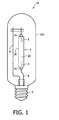
- a schematic Figure of an embodiment of such a metal halide lamp is depicted in Figure 1 .
- metal halide lamps here indicated with reference number 25, comprise a discharge vessel 1 surrounded by an outer envelope 105 with clearance and having a ceramic wall or vessel wall 30 (with internal surface 12 and external surface 13) which encloses a discharge space 22 filled with a filling comprising an inert gas, such as xenon (Xe) or argon (Ar), and an ionisable salt, and in said discharge space 22 two electrodes 4 and 5 are arranged.
- an inert gas such as xenon (Xe) or argon (Ar)
- the discharge vessel 1 is surrounded by outer bulb or outer envelop 105 which is provided with a lamp cap 2 at one end.
- the outer envelop 105 may be in vacuum or filled with an inert gas such as nitrogen.
- a discharge will extend between the electrodes 4,5 when the lamp is operating.
- the electrode 4 is connected to a first electrical contact forming part of the lamp cap 2 via a current lead through conductor 8.
- the electrode 5 is connected to a second electrical contact forming part of the lamp cap 2 via a current lead through conductor 9.
- the discharge vessel 1 further comprises protruding end plugs 34,35, each at one side and each arranged to enclose at least part of the electrodes 4,5, respectively.
- the invention is also directed to discharge vessels 1 which do not comprise such protruding end plugs 34,35 (see also below).
- the ceramic wall 30 is understood to mean both a wall of metal oxide such as, for example, sapphire or densely sintered polycrystalline Al 2 O 3 and metal nitride, for example, AlN. According to the state of the art, these ceramics are well suited to form translucent discharge vessel walls 30.
- FIG. 2 shows in more detail a preferred embodiment of the lamp.
- a shaped discharge vessel 1 is schematically depicted.
- the lamp shown is not drawn on scale.
- Figure 2 shows that the electrodes have electrode tips 4b,5b having a mutual interspacing so as to define a discharge path between them during operation of the lamp.
- each electrode 4,5 is supported by a current lead through conductor 20,21 entering the discharge vessel 1.
- the current lead through conductors 20,21 preferably consist of a first part made of an halide resistant material, such as for instance a Mo-Al 2 O 3 cermet, and a second part made of for instance niobium.
- Niobium is chosen because this material has a coefficient of thermal expansion corresponding to that of the discharge vessel 1 in order to prevent leakage of the lamp 25.
- Other possible constructions are known, for example, from EP0587238 (wherein a Mo coil-to-rod configuration is described).
- the current lead through conductors may be sealed into the protruding end plugs 34,35 with seals 10.
- the ionisable filling in general comprises a salt (including a mixture of salts), which herein comprises 3.5-82 mol % sodium iodide, 0.5-8.5 mol % thallium iodide, 14-92 mol % calcium iodide, 0.5-5.5 mol % cerium iodide and 0.5-5 mol % indium iodide, the mol percentages being relative to the total amount of ionisable salt filling.
- a salt including a mixture of salts
- the ionisable salt filling comprises 4-30 mol % sodium iodide, 0.5-3.5 mol % thallium iodide, and 65-92 mol % calcium iodide, as well as 0.5-5.5 mol % cerium iodide (preferably 1.5-3.5 mol %) and 0.5-5 mol % indium iodide (preferably 0.5-3 mol %).
- the ionisable salt filling comprises at least 70 mol % calcium iodide, such as 75 mol %, relative to the total amount of ionisable salt filling.
- the ionisable salt filling comprises 3.5-25 mol % sodium iodide, such as 3.5-20 mol %, relative to the total amount of ionisable salt filling.
- the ionisable filling used in the invention may further comprise one or more components selected from the group consisting of iodides of Li, K, Rb, Cs, Mg, Sr, Ba, Sc, Y, La, Pr, Nd, Sm, Eu, Gd, Tb, Dy, Ho, Er, Tm, Yb, Lu, Sn, Mn and Zn, especially one or more components selected from the group consisting of LiI, KI, RbI, CsI, MgI 2 , CaI 2 , SrI 2 , BaI 2 , ScI 3 , YI 3 , LaI 3 , PrI 3 , NdI 3 , SmI 2 , EuI 2 , GdI 3 , TbI 3 , DyI 3 , HoI 3 , ErI 3 , TmI 3 , YbI 2 , LuI 3 , SnI 2 , MnI 2 and ZnI 2 .
- the discharge space 22 contains in general Hg (mercury) and further contains a starter gas such as Ar (argon) or Xe (xenon), as known in the art.
- the discharge vessel 1 further contains mercury (Hg).
- the discharge vessel 1 is mercury-free.
- the amounts of filling do not take into account the amount of mercury present.
- Mercury is dosed to the discharge vessel 1 in amounts known to the person skilled in the art.
- the ionisable filling comprises NaI, TlI, CaI 2 and X-iodide, where X is one or more elements selected from the group comprising rare earth metals, yttrium and scandium, and X comprises at least Ce.
- X can be formed by a single element or by a mixture of two or more elements.
- the terms "rare earth and "X" include Sc and Y.
- Rare earth elements include lanthanum, cerium, praseodymium, neodymium, samarium, europium, gadolinium, terbium, dysprosium, holmium, erbium, thulium, ytterbium and lutetium.
- elements other than Ce are selected from the group comprising Sc, Y, La, Pr, Gd, Tb, Dy, Ho, Er, Tm, Yb, Lu, and Nd.
- the elements Sc, Y, La, Ce, Pr, Nd, Gd, Tb, Dy, Ho, Er, Tm, Yb, Lu, Na, Tl, Ca and I stand for scandium, yttrium, lanthanum, cerium, praseodymium, neodymium, gadolinium, terbium, dysprosium, holmium, erbium, thulium, ytterbium, lutetium, sodium, thallium, calcium and iodine, respectively.
- X-iodide may also include a plurality of different iodides.
- the ionisable filling further comprises halides, especially iodides, of manganese.
- X is the total amount of rare earth, scandium and yttrium and the molar percentage ratio X-iodide / (NaI + TlI + CaI 2 + InI + X- iodide (+ optionally MnI 2 )) lies above 0 % up to a maximum of 10 %, in particular in the range of 0.5-7 %, more in particular in the range of 1-6 %.
- the preferred ratio Ce-iodide / is 0.5-5.5 % (as defined above).
- the total molar percentage ratio of these metals is larger than 0% and maximally 10%, while Ce being in the range of 0.5-5.5 %.
- X an amount of X
- experiments have shown that the electrodes may reach too high temperature values to operate satisfactorily.
- amounts of X above the indicated maximum it becomes more difficult to maintain a W-halide cycle that prevents or reduces the deposition of tungsten on the wall of the discharge vessel 1 during lamp operation.
- X being the total amount of rare earth (including Sc and Y), the molar percentage ratio CaI 2 / (NaI +T1L +CaI 2 + InI + X-iodide (+ optionally MnI 2 )) is in the range of 14-92 %.
- the amount of NaI, TlL, CaI 2 , InI and X-iodide (+ optionally MnI 2 ) is in the range of 0.001-0.5 g/cm 3 , in particular in the range of 0.005-0.3 g/cm 3 .
- the volume of the discharge vessel particularly ranges between 0.05-10.0 cm 3 , depending on the lamp power.
- Characteristic amounts of ionisable gas fillings are salt doses of about 5-70 mg, such as 5-50 mg.
- Nominal operation i.e. stable nominal operation, means in this respect that the lamp 25 is operated at a power and voltage for which it is designed. The designed power of the lamp 25 is called the nominal power or rated power.
- Wall load as defined herein is the lamp power divided by the surface of the external wall 13 excluding the optional protruding plugs 34,35.
- Characteristic wall loads of the discharge vessel wall surface 13 of the lamp 25 in accordance with the invention are in the range of about 20-30 W/cm 2 , especially in the range of about 20-28 W/cm 2 (i.e. the external wall load at nominal operation power).
- the loads of the internal wall surface 12 are generally in the range of about 25-35 W/cm 2 .
- the term "dimming range” refers to the range wherein the lamp can be dimmed without substantially affecting the light-technical properties, assuming nominal operation to be 100 % (which is also indicated as 100% of nominal operation).
- the lamp of the invention can be dimmed in a range to about 50 % of nominal operation (i.e. 50-100 % of nominal operation), while having a Ra of at least 80, or even at least 85 (see also table 4 below).
- a Ra of at least 80 can be obtained even in the dimming range of about 40-100 % of nominal operation.
- an efficacy above 80 lm/W, or even above 85 lm/W can be obtained, while in the range of about 40-100 % of nominal operation, over the whole range, the efficacy is over about 75 lm/W.
- the color temperature in the dimming range of 50-100% of nominal operation may vary in the range of about 2800-5000 K, in a variant over a range of at least 1500 K.
- the deviation from the BBL for large dimming percentages of the lamp of the invention is within the range of about 15 SDCM, more preferably 10 SDCM.
- the lamp of the invention provides a color shift as a function of dimming substantially parallel to the BBL, there is, unlike prior art lamps (see also Figure 5 ), no substantial increase in deviation from the BBL with dimming.
- Figure 5 shows for a lamp according to the invention (b) and prior art lamps (c and d; not containing InI) curves for the position of the color point as a function of the dimming percentage between 100-30% of nominal operation).
- the color point shows a sharp deviation from the color points of the dimming range. Consequently, a curve representing the position of the color point as a function of the power of the lamp with such high wall loads may not be substantially parallel to the BBL.
- FIG. 3 shows an embodiment of discharge vessel 1 of a metal halide lamp 25 having a ceramic wall 30 which encloses a discharge space 22 containing an ionisable filling.
- Two, for instance, tungsten electrodes 4,5 with tips 4b, 5b at a mutual distance L3, are located in the discharge vessel 1.
- the discharge vessel 1 is closed by means of ceramic protruding end plugs 34,35 which enclose, with a small clearance, current lead-through conductors 20,21 to electrodes 4,5 positioned in the discharge vessel 1 and are connected to these conductors 20,21 in a gas tight manner by means of a melting-ceramic joint or sealing 10 at ends remote from the discharge space 22 (see also above).
- the invention is not confined to the embodiment depicted in Figure 3 ; see for instance also Figure 4 .
- the description of the discharge vessel 1 below first concentrates on the general aspects of the shaped discharge vessel 1 of the lamp 25 of the invention, and then deals with some preferred embodiments.
- the discharge vessel 1 has a vessel wall 30 enclosing the discharge space 22 containing the ionisable filling.
- the discharge space encloses electrodes 4,5 with electrode tips 4b,5b.
- the discharge vessel 1 has a spheroid-like shape with a main axis 60 and an outer length L1, a largest internal diameter d1 and a largest outer diameter d2.
- the discharge vessel 1 further has curved extremities 114,115 and openings 54,55 at (or in) the curved extremities 114,115. These openings 54,55 are arranged to surround the electrodes 4,5. These curved extremities 114,115 have a curvature with radius r3.
- the discharge vessel 1 has a spheroid-like shape, more especially a prolate spheroid-like shape (i.e. a shape like a rugby ball).
- a prolate spheroid has a main axis, here indicated with reference number 60, and a minor axis, here indicated with reference number 61; the main axis 60 is larger than the minor axis 61.
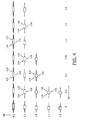
- Figure 4 schematically depicts a number of possible discharge vessel constructions, both within and outside the aspect ratio and shape parameter values as described herein.
- the term "spheroid-like shape" is used since the discharge vessel 1 of the lamp 25 of the invention may have shapes close to spherical at low aspect ratios AR and at small values of the first shape parameter SP.
- the discharge vessel 1 substantially has a spheroid shape.
- the aspect ratio AR further increases, especially above about 1.5
- the discharge vessel 1 can be characterized by a spheroid having a central cylindrical part.
- this is indicated with cylindrical intermediate part 116, which may be (substantially) absent at low aspect ratios and low shape parameters but which is present especially at relatively high aspect ratios.
- the discharge vessel according to a preferred embodiment of the lamp of the invention has shapes in the range from close-to-spherical to cigar-like. These shapes are herein indicated as "spheroid-like shapes”.
- the discharge vessel 1 since the discharge vessel 1 according to a preferred embodiment has a spheroid-like shape, this also implies that discharge vessel 1 having a shape close to spherical has a radius r3 that is substantially constant over the curved extremities 114,115. However, when the discharge vessel 1 has a shape deviating from close to spherical and has a shape that is more like a spheroid, the radius r3 may in some embodiments vary over the curved extremities 114,115. Radius r3 may therefore also be indicated as mean radius r3. As will be clear to the person skilled in the art, the mean curvature 1/r3 can then be derived by integration of the local curvature along the contour of the curved part and dividing by the length of the contour along which the curvature is integrated
- the discharge vessel 1 of the lamp 25 is substantially symmetrical around main axis 60.
- a coordinate system is drawn, wherein the main axis 60 is along the y axis, and the minor axis 61 is along the z axis, perpendicular to the y axis.
- the discharge vessel 1 is essentially rotationally symmetric around main axis 60.
- a longitudinal axis 100 through the discharge vessel 1 is drawn.
- Main axis 60 coincides with part of this longitudinal axis.
- the optional protruding end plugs 34 and 35 are also rotationally symmetric around the longitudinal axis 100 of the discharge vessel (and thus in fact also around main axis 60).
- the discharge vessel has a largest internal radius r1, i.e. the length of a perpendicular from main axis 60 to the internal surface 12 of vessel wall 30 and a largest external radius r2, i.e. the length of a perpendicular from main axis 60 to the external surface 13 of vessel wall 30.
- the discharge vessel 1 has a wall thickness w1 which is equal to r2-r1.
- the wall thickness w1 is substantially equal all over the discharge vessel wall 30.
- the discharge vessel 1 has a wall thickness w1 in the range of 0.5-2 mm, more preferably about 0.8-1.2 mm.
- the discharge vessel 1 also has a largest internal diameter d1, i.e. the largest diameter of the vessel from internal surface 12 to an opposite internal surface measured along a perpendicular to main axis 60.
- This internal diameter d1 is equal to the length of the minor axis 61 within the discharge vessel 1.
- the discharge vessel 1 has a maximum external diameter d2.
- the external diameter d2 is equal to the length of the minor axis 61.
- (d1+d2)/2 w1.
- the part or region of the discharge vessel 1 with the largest diameter d2 is indicated as intermediate region 116.
- the discharge vessel 1 of the invention can be seen as two curved parts or curved extremities 114,115 between which an intermediate region 116 is found which may for instance be cylindrical. These regions or parts 114, 115 and 116 are only indicated for the sake of simplicity.
- the extremities 114 and 115 of the discharge vessel 1 are curved. Note that in the Figures here, protruding end plugs 34 and 35 are connected to these extremities. The protruding end plugs are optional, and are also discussed below. These curved extremities have a certain curvature (or mean curvature) with radius r3 (see above). Since the discharge vessel is rotationally symmetric around its main axis 60, and preferably also symmetric around its minor axis 61, the curvature of these curved extremities 114,115 is the same at each side of an intersection (vertex) of the main axis 60 and minor axis 61.
- the curved extremities 114 and 115 have openings 54 and 55 which are arranged to enclose or surround at least partially the electrodes 4 and 5.
- the electrodes 4,5, or more precisely the current lead-through conductors 20,21 may be directly sintered to the discharge vessel wall 30, but may also be partially integrated into protruding end plugs 34,35. Further, the current lead-through conductors 20,21 may also be directly sintered into the protruding end plugs 34,35, respectively, or may be sealed into the protruding end plugs 34,35 with seals 10. Anyhow, the current lead-through conductors 20,21 are arranged in discharge vessel 1 in a vacuum tight manner.
- the electrodes 4,5 enter the discharge vessel 1 via openings 54 and 55, which openings 54,55 surround at least part of the electrodes.
- the distance from the openings 54,55 to each other, or the distance from one side of the main axis 60 to the other side of the main axis 60 is indicated as length L1 (or outer length L1) of the discharge vessel 1.
- length L1 is equal to the length of the main axis 60
- diameter d2 is equal to the length of the minor axis 61.
- the electrodes 4,5 have electrode tips 4b and 5b, which are arranged at a distance L3 from each other. This distance is often also indicated as ED or also EA. Note that the electrodes 4,5 are located in the discharge vessel 1 along main axis 60.
- lamps 25 are provided with excellent optical properties, maintenance, efficacy and universal burning.
- the lamp 25 of the invention has the advantages of high efficacy, good maintenance, a universal burning position and good optical properties (relatively high values for Ra and good color temperature CCT) and a long life. Efficacies of at least 100 lm/W during operation (stable operation at rated power) can be reached, even efficacies of at least 105 lm/W can be obtained for the lamp 25 of the invention (at stable operation at rated power).
- lamps 25 wherein the first shape parameter is 0.75 ⁇ r3/d2 ⁇ 0.9 and/or wherein the aspect ratio is 1.3 ⁇ L1/d2 ⁇ 1.7 are advantageous lamps in terms of efficacy, color rendering and long life.
- Lamps of any wattage can be made, such as between about 20 W nominal operation power and about 150 W nominal operation power.
- lamps can be made with wattages above 100W, preferably above 150 W (even up to or above 1000W) that are suitable for a universal burning position.
- the rated power of the lamp 25 may be larger than 100W, preferably in the order of about 150W or higher, preferably in the range of 150-1000W, although higher powers are also possible.
- Characteristic wattages are for instance 150W, 210W, 315W, 400W, 600W and 1000W. These values refer to nominal operation power.
- lamps can be made with powers at nominal operation in the range between 20 and 1000 W.
- the ratio of the distance between the electrode tips 4b,5b L3 and the length L1 of the discharge vessel 1 is advantageously in the range of 0.4-0.7.
- the distance from the electrode (tips) to the discharge vessel wall 30, i.e. especially its internal surface 12, is sufficient such that crack formation is prevented or diminished.
- the ratio L3/L1, indicated as second space parameter SPP is preferably 0.4 ⁇ L3/L1 ⁇ 0.7.
- the discharge vessel 1 further comprises protruding end plugs 34,35, such as schematically depicted in Figures 2-4 .
- These protruding end plugs 34,35 may be integral with with discharge vessel wall 30.
- the protruding end plugs 34,35 are rotationally symmetric around longitudinal axis 100, and are arranged to enclose the current lead-through conductors 20 and 21, respectively.
- the conductors 20,21 may be sealed into the protruding end plugs 34,35 by means of sealing 10 or may directly be sealed into the plugs 34,35, without using a separate sealing material to form sealing 10.
- the protruding end plugs have an internal diameter d6, d7 and an external diameter d4,d5, respectively.
- the protruding end plugs 34,35 have a wall width w2, which is preferably substantially equal to wall width w1 of ceramic discharge vessel wall 30.
- the plugs 34,35 have a length L4,L5, respectively, which are preferably substantially equal.
- the openings 54,55 at the curved extremities 114,115 may in an embodiment be arranged to surround the electrodes 4,5 (especially when no protruding end plugs 34,35 are used) and may in another embodiment be arranged to surround the current lead-through conductors 20,21.
- the wall 30 of discharge vessel 1 may at the end of the extremities 114,115 show a further curvature, different from the curvature with radius r3, in the direction of the protruding end plugs 34,35.
- This curvature is indicated with radius r4.
- This curved part is in general only a minor part of the curved extremities 114,115.
- the curvature radius r4 is in general in the order of about 0.5-3.0 mm, preferably 1.0-2.0 mm.
- the invention also relates to a metal halide lamp 25 to be used in a vehicle headlamp and to a headlamp comprising the lamp 25 according to the invention.
- the lamp according to the invention (indicated with “b”; this is the lamp with 2.7 mol Inl) "follows” the BBL (indicated with “a") while dimming from 100% of nominal power (i.e. nominal operation) to about 30% of nominal power.
- the distance to the BBL is in the range of 15 SDCM, more preferably 10 SDCM (i.e. 0-10 SDCM).
- lamps without the herein prescribed InI as shown in Figure 5 with reference “c” and “d” ("d” is comparable to the reference lamp indicated in the above tables; "c” is another type of ceramic discharge lamps not comprising Inl (master color CDM-T 70 W/830 lamp), substantially deviate from the BBL, leading to a lamp with undesired light-technical properties at powers below nominal operation.
- point AA the color point of the inventive lamp having 2.7 mol % In when the lamp is operated with a wall loading on the outside surface of 35.3 W/cm 2 , which means an operating power of 138 W, being more than the nominal value.
- the color point deviates sharply from the color points in the power range of 100% to 30% of the nominal power.
- the color point has the coordinates (x,y) (0.410; 0.375).
Landscapes
- Discharge Lamp (AREA)
- Vessels And Coating Films For Discharge Lamps (AREA)
Claims (14)
- Halogen-Metalldampflampe (25) mit einem keramischen Entladungsgefäß (1), wobei das Entladungsgefäß (1) ein Entladungsvolumen (11) einschließt, das eine ionisierbare Salzfüllung enthält, wobei die ionisierbare Salzfüllung 4-30 Mol-% Natriumiodid, 0,5-3,5 Mol-% Thalliumiodid, 65-92 Mol-% Calciumiodid, 0,5-5,5 Mol-% Ceriodid sowie 0,5-3,5 Mol-% Indiumiodid umfasst, wobei die Molprozente auf die Gesamtmenge der ionisierbaren Salzfüllung bezogen sind.
- Halogen-Metalldampflampe (25) nach Anspruch 1, wobei die ionisierbare Salzfüllung 0,5-3 Mol-% Indiumiodid umfasst.
- Halogen-Metalldampflampe (25) nach einem der vorangegangenen Ansprüche, wobei die Lampe eine externe Wandbelastung von 20-30 W/cm2 aufweist.
- Halogen-Metalldampflampe (25) nach einem der vorangegangenen Ansprüche, wobei die ionisierbare Salzfüllung weiterhin ein oder mehrere Elemente umfasst, die aus der Gruppe, bestehend aus Scandium, Yttrium sowie anderen Seltenerdmetallen als Ce, ausgewählt werden, wobei das Molprozentverhältnis X-Iodid / (Nal + TII + Cal2 + Inl + X-Iodid) über 0% und maximal 10% beträgt, vorzugsweise jedoch im Bereich von 0,5-7%, noch besser im Bereich von 1-6% liegt, und wobei X-Iodid auf Ce und das optionale Element oder mehrere Elemente, die aus der Gruppe, bestehend aus Scandium, Yttrium sowie anderen Seltenerdmetallen als Ce, ausgewählt werden, bezogen ist.
- Halogen-Metalldampflampe (25) nach einem der vorangegangenen Ansprüche, wobei die Menge an Nal, Tll, Cal2, Inl und X-Iodid in dem Entladungsgefäß (1) im Bereich von 0,001-0,5 g/cm3, vorzugsweise im Bereich von 0,025-0,3 g/cm3, liegt, wobei X-Iodid auf Ce und das optionale Element oder mehrere Elemente, die aus der Gruppe, bestehend aus Scandium, Yttrium sowie anderen Seltenerdmetallen als Ce, ausgewählt werden, bezogen ist.
- Halogen-Metalldampflampe (25) nach einem der vorangegangenen Ansprüche, wobei diese eine Leuchtstärke von mindestens 100 Im/W bei Nennbetrieb und eine Leuchtstärke von mindestens 80 Im/W bei 50% Nennbetrieb sowie einen CRI von mindestens 85 bei Nennbetrieb im Bereich von 50-100 % aufweist.
- Halogen-Metalldampflampe (25) nach einem der vorangegangenen Ansprüche, wobei diese während des Betriebs Licht mit einer Farbtemperatur CCT über 2800 K emittiert.
- Halogen-Metalldampflampe (25) nach einem der vorangegangenen Ansprüche, wobei die ionisierbare Salzfüllung weiterhin 0,5-10 Mol-% Mn-iodid umfasst.
- Halogen-Metalldampflampe (25) nach einem der vorangegangenen Ansprüche, wobei das Entladungsgefäß (1) eine Gefäßwand (30) aufweist, die einen Entladungsraum (22) mit einer ionisierbaren Füllung einschließt, wobei der Entladungsraum (22) weiterhin Elektroden (4,5) mit Elektrodenspitzen (4b,5b) einschließt, die einander gegenüberliegend angeordnet und so vorgesehen sind, dass sie während des Betriebs der Lampe (25) einen Entladungsbogen zwischen den Elektrodenspitzen (4b,5b) definieren, wobei das Entladungsgefäß (1) eine kugelähnliche Form mit einer Hauptachse (60) und einer Länge L1 aufweist, wobei das Entladungsgefäß (1) einen größten Innendurchmesser d1 und einen größten Außendurchmesser d2 hat, wobei das Entladungsgefäß (1) weiterhin gekrümmte Extremitäten (114,115) aufweist, wobei die gekrümmten Extremitäten (114,115) eine Krümmung mit Radius r3 haben, wobei ein Aspektverhältnis L1/d2 = 1,1≤L1/d2≤2,2 und wobei ein Formparameter r3/d2 = 0,7≤r3/d2≤1,1.
- Halogen-Metalldampflampe (25) nach Anspruch 9, wobei die Elektrodenspitzen (4b,5b) in einem Abstand L3 voneinander angeordnet sind und wobei 0,4≤L3/L1≤0,7.
- Halogen-Metalldampflampe (25) nach einem der Ansprüche 9-10, wobei der Formparameter 0,75≤r3/d2≤0,9 ist.
- Halogen-Metalldampflampe (25) nach einem der Ansprüche 9-11, wobei das Aspektverhältnis 1,3≤L1/d2≤1,7 ist.
- Halogen-Metalldampflampe (25) nach einem der Ansprüche 9 bis 12, wobei das Entladungsgefäß (1) eine Wanddicke (w1) im Bereich von 0,5-2 mm aufweist.
- Halogen-Metalldampflampe (25) nach einem der Ansprüche 9 bis 13, wobei das Entladungsgefäß (1) weiterhin hervorstehende Endstopfen (34,35) umfasst und die hervorstehenden Endstopfen (34,35) zumindest einen Teil der Elektroden (4,5) umgeben.
Priority Applications (1)
| Application Number | Priority Date | Filing Date | Title |
|---|---|---|---|
| EP08763038A EP2145347B1 (de) | 2007-04-20 | 2008-04-18 | Metallhalogenlampe mit ionisierbarer salzfüllung |
Applications Claiming Priority (3)
| Application Number | Priority Date | Filing Date | Title |
|---|---|---|---|
| EP07106601 | 2007-04-20 | ||
| EP08763038A EP2145347B1 (de) | 2007-04-20 | 2008-04-18 | Metallhalogenlampe mit ionisierbarer salzfüllung |
| PCT/IB2008/051492 WO2008129486A2 (en) | 2007-04-20 | 2008-04-18 | Metal halide lamp comprising an ionisable salt filling |
Publications (2)
| Publication Number | Publication Date |
|---|---|
| EP2145347A2 EP2145347A2 (de) | 2010-01-20 |
| EP2145347B1 true EP2145347B1 (de) | 2011-01-05 |
Family
ID=39876043
Family Applications (1)
| Application Number | Title | Priority Date | Filing Date |
|---|---|---|---|
| EP08763038A Not-in-force EP2145347B1 (de) | 2007-04-20 | 2008-04-18 | Metallhalogenlampe mit ionisierbarer salzfüllung |
Country Status (7)
| Country | Link |
|---|---|
| US (1) | US8227991B2 (de) |
| EP (1) | EP2145347B1 (de) |
| JP (1) | JP5220096B2 (de) |
| CN (1) | CN101669189B (de) |
| AT (1) | ATE494628T1 (de) |
| DE (1) | DE602008004334D1 (de) |
| WO (1) | WO2008129486A2 (de) |
Families Citing this family (13)
| Publication number | Priority date | Publication date | Assignee | Title |
|---|---|---|---|---|
| US8207674B2 (en) * | 2008-02-18 | 2012-06-26 | General Electric Company | Dose composition suitable for low wattage ceramic metal halide lamp |
| DE102008056173A1 (de) * | 2008-11-06 | 2010-05-12 | Osram Gesellschaft mit beschränkter Haftung | Hochdruckentladungslampe |
| JP2012515413A (ja) * | 2009-01-14 | 2012-07-05 | コーニンクレッカ フィリップス エレクトロニクス エヌ ヴィ | 高い色温度を持つセラミックガス放電メタルハライドランプ |
| WO2011121492A2 (en) * | 2010-04-02 | 2011-10-06 | Koninklijke Philips Electronics N.V. | Metal halide lamp |
| US8339044B2 (en) | 2010-12-28 | 2012-12-25 | General Electric Company | Mercury-free ceramic metal halide lamp with improved lumen run-up |
| CN103563046B (zh) * | 2011-03-31 | 2016-10-19 | 皇家飞利浦有限公司 | 陶瓷放电金属卤化物(cdm)灯及其制造方法 |
| US8552646B2 (en) | 2011-05-05 | 2013-10-08 | General Electric Company | Low T1I/low InI-based dose for dimming with minimal color shift and high performance |
| US20130127336A1 (en) * | 2011-11-17 | 2013-05-23 | General Electric Company | Influence of indium iodide on ceramic metal halide lamp performance |
| JP5874589B2 (ja) * | 2012-09-18 | 2016-03-02 | 岩崎電気株式会社 | セラミックメタルハライドランプ |
| CN104183462A (zh) * | 2013-05-28 | 2014-12-03 | 海洋王照明科技股份有限公司 | 陶瓷金卤灯电极及陶瓷金卤灯 |
| US20150015144A1 (en) * | 2013-07-09 | 2015-01-15 | General Electric Company | High efficiency ceramic lamp |
| CN103887144A (zh) * | 2014-03-28 | 2014-06-25 | 溢阳(太仓)光电科技有限公司 | 一种高光效高显色性氙气金卤灯 |
| CN103951244B (zh) * | 2014-05-08 | 2016-01-13 | 宁波大学 | 稀土离子掺杂的Cs2LiYI6微晶玻璃及其制备方法 |
Family Cites Families (19)
| Publication number | Priority date | Publication date | Assignee | Title |
|---|---|---|---|---|
| NL8502509A (nl) | 1985-09-13 | 1987-04-01 | Philips Nv | Hogedrukkwikdampontladingslamp. |
| JP3635797B2 (ja) * | 1996-07-29 | 2005-04-06 | 日本電池株式会社 | 金属蒸気放電灯 |
| DE19645960A1 (de) | 1996-11-07 | 1998-05-14 | Patent Treuhand Ges Fuer Elektrische Gluehlampen Mbh | Keramisches Entladungsgefäß |
| JP2003168391A (ja) * | 2001-09-20 | 2003-06-13 | Koito Mfg Co Ltd | 放電ランプ装置用水銀フリーアークチューブ |
| EP1466345A2 (de) * | 2002-01-04 | 2004-10-13 | Philips Electronics N.V. | Entladungslampe |
| DE20205707U1 (de) | 2002-04-12 | 2003-05-28 | Patent-Treuhand-Gesellschaft für elektrische Glühlampen mbH, 81543 München | Keramisches Entladungsgefäß mit Innenradius |
| US6819050B1 (en) | 2003-05-02 | 2004-11-16 | Matsushita Electric Industrial Co., Ltd. | Metal halide lamp with trace T1I filling for improved dimming properties |
| US6844687B1 (en) * | 2003-09-26 | 2005-01-18 | Osram Sylvania Inc. | Method of operating a discharge lamp |
| JP4062234B2 (ja) * | 2003-10-28 | 2008-03-19 | 松下電器産業株式会社 | メタルハライドランプとそれを用いた点灯装置 |
| US8106590B2 (en) | 2004-03-08 | 2012-01-31 | Koninklijke Philips Electronics N.V. | Vehicle headlamp |
| WO2005088675A1 (en) * | 2004-03-08 | 2005-09-22 | Koninklijke Philips Electronics N.V. | Metal halide lamp |
| US7012375B2 (en) * | 2004-03-23 | 2006-03-14 | Osram Sylvania Inc. | Thallium-free metal halide fill for discharge lamps and discharge lamp containing same |
| JP2008518391A (ja) * | 2004-10-26 | 2008-05-29 | コーニンクレッカ フィリップス エレクトロニクス エヌ ヴィ | メタルハライドランプ |
| US7268495B2 (en) * | 2005-01-21 | 2007-09-11 | General Electric Company | Ceramic metal halide lamp |
| US7414368B2 (en) * | 2005-01-21 | 2008-08-19 | General Electric Company | Ceramic metal halide lamp with cerium-containing fill |
| EP1869694A2 (de) * | 2005-04-08 | 2007-12-26 | Koninklijke Philips Electronics N.V. | Hochdruckentladungslampe |
| US20090278457A1 (en) * | 2005-04-29 | 2009-11-12 | Koninklijke Philips Electronics, N.V. | Metal halide lamp |
| DE102005025155A1 (de) * | 2005-06-01 | 2006-12-07 | Patent-Treuhand-Gesellschaft für elektrische Glühlampen mbH | Hochdrucklampe und zugehöriges Betriebsverfahren für den Resonanzbetrieb von Hochdrucklampen im longitudinalen Mode und zugehöriges System |
| JP2008218192A (ja) * | 2007-03-05 | 2008-09-18 | Osram Melco Toshiba Lighting Kk | 高圧放電ランプおよび照明器具 |
-
2008
- 2008-04-18 EP EP08763038A patent/EP2145347B1/de not_active Not-in-force
- 2008-04-18 CN CN2008800127503A patent/CN101669189B/zh not_active Expired - Fee Related
- 2008-04-18 DE DE602008004334T patent/DE602008004334D1/de active Active
- 2008-04-18 JP JP2010503656A patent/JP5220096B2/ja not_active Expired - Fee Related
- 2008-04-18 US US12/595,642 patent/US8227991B2/en not_active Expired - Fee Related
- 2008-04-18 AT AT08763038T patent/ATE494628T1/de not_active IP Right Cessation
- 2008-04-18 WO PCT/IB2008/051492 patent/WO2008129486A2/en not_active Ceased
Also Published As
| Publication number | Publication date |
|---|---|
| WO2008129486A2 (en) | 2008-10-30 |
| US8227991B2 (en) | 2012-07-24 |
| WO2008129486A3 (en) | 2009-04-02 |
| DE602008004334D1 (de) | 2011-02-17 |
| ATE494628T1 (de) | 2011-01-15 |
| JP5220096B2 (ja) | 2013-06-26 |
| CN101669189A (zh) | 2010-03-10 |
| JP2010525521A (ja) | 2010-07-22 |
| CN101669189B (zh) | 2011-11-23 |
| EP2145347A2 (de) | 2010-01-20 |
| US20100052531A1 (en) | 2010-03-04 |
Similar Documents
| Publication | Publication Date | Title |
|---|---|---|
| EP2145347B1 (de) | Metallhalogenlampe mit ionisierbarer salzfüllung | |
| US8390196B2 (en) | Methal halide lamp comprising a shaped ceramic discharge vessel | |
| US7268495B2 (en) | Ceramic metal halide lamp | |
| JP3825009B2 (ja) | メタルハライドランプ | |
| JP4531946B2 (ja) | 水銀を含まないメタルハライドランプ | |
| EP2115766B1 (de) | Metallhalogenlampe | |
| US20030020408A1 (en) | Metal halide lamp | |
| EP2313910B1 (de) | Metallhalogenlampe | |
| US20110273089A1 (en) | Ceramic gas discharge metal halide lamp with high color temperature | |
| JP3981301B2 (ja) | メタルハライドランプ | |
| EP1878040B1 (de) | Metallhalogenidlampe mit verbesserter Emission im Roten | |
| US20130113372A1 (en) | Dysprosium-halide-containing high-pressure discharge lamp | |
| US8339044B2 (en) | Mercury-free ceramic metal halide lamp with improved lumen run-up | |
| US20050082988A1 (en) | Metal-halide lamp | |
| WO2011121492A2 (en) | Metal halide lamp | |
| WO2010007576A1 (en) | Metal halide lamp |
Legal Events
| Date | Code | Title | Description |
|---|---|---|---|
| PUAI | Public reference made under article 153(3) epc to a published international application that has entered the european phase |
Free format text: ORIGINAL CODE: 0009012 |
|
| 17P | Request for examination filed |
Effective date: 20091120 |
|
| AK | Designated contracting states |
Kind code of ref document: A2 Designated state(s): AT BE BG CH CY CZ DE DK EE ES FI FR GB GR HR HU IE IS IT LI LT LU LV MC MT NL NO PL PT RO SE SI SK TR |
|
| AX | Request for extension of the european patent |
Extension state: AL BA MK RS |
|
| GRAP | Despatch of communication of intention to grant a patent |
Free format text: ORIGINAL CODE: EPIDOSNIGR1 |
|
| DAX | Request for extension of the european patent (deleted) | ||
| GRAS | Grant fee paid |
Free format text: ORIGINAL CODE: EPIDOSNIGR3 |
|
| GRAA | (expected) grant |
Free format text: ORIGINAL CODE: 0009210 |
|
| AK | Designated contracting states |
Kind code of ref document: B1 Designated state(s): AT BE BG CH CY CZ DE DK EE ES FI FR GB GR HR HU IE IS IT LI LT LU LV MC MT NL NO PL PT RO SE SI SK TR |
|
| REG | Reference to a national code |
Ref country code: GB Ref legal event code: FG4D |
|
| REG | Reference to a national code |
Ref country code: CH Ref legal event code: EP |
|
| REG | Reference to a national code |
Ref country code: IE Ref legal event code: FG4D |
|
| REF | Corresponds to: |
Ref document number: 602008004334 Country of ref document: DE Date of ref document: 20110217 Kind code of ref document: P |
|
| REG | Reference to a national code |
Ref country code: DE Ref legal event code: R096 Ref document number: 602008004334 Country of ref document: DE Effective date: 20110217 |
|
| REG | Reference to a national code |
Ref country code: NL Ref legal event code: T3 |
|
| PG25 | Lapsed in a contracting state [announced via postgrant information from national office to epo] |
Ref country code: SI Free format text: LAPSE BECAUSE OF FAILURE TO SUBMIT A TRANSLATION OF THE DESCRIPTION OR TO PAY THE FEE WITHIN THE PRESCRIBED TIME-LIMIT Effective date: 20110105 |
|
| LTIE | Lt: invalidation of european patent or patent extension |
Effective date: 20110105 |
|
| PG25 | Lapsed in a contracting state [announced via postgrant information from national office to epo] |
Ref country code: IS Free format text: LAPSE BECAUSE OF FAILURE TO SUBMIT A TRANSLATION OF THE DESCRIPTION OR TO PAY THE FEE WITHIN THE PRESCRIBED TIME-LIMIT Effective date: 20110505 Ref country code: GR Free format text: LAPSE BECAUSE OF FAILURE TO SUBMIT A TRANSLATION OF THE DESCRIPTION OR TO PAY THE FEE WITHIN THE PRESCRIBED TIME-LIMIT Effective date: 20110406 Ref country code: NO Free format text: LAPSE BECAUSE OF FAILURE TO SUBMIT A TRANSLATION OF THE DESCRIPTION OR TO PAY THE FEE WITHIN THE PRESCRIBED TIME-LIMIT Effective date: 20110405 Ref country code: PT Free format text: LAPSE BECAUSE OF FAILURE TO SUBMIT A TRANSLATION OF THE DESCRIPTION OR TO PAY THE FEE WITHIN THE PRESCRIBED TIME-LIMIT Effective date: 20110505 Ref country code: ES Free format text: LAPSE BECAUSE OF FAILURE TO SUBMIT A TRANSLATION OF THE DESCRIPTION OR TO PAY THE FEE WITHIN THE PRESCRIBED TIME-LIMIT Effective date: 20110416 Ref country code: LT Free format text: LAPSE BECAUSE OF FAILURE TO SUBMIT A TRANSLATION OF THE DESCRIPTION OR TO PAY THE FEE WITHIN THE PRESCRIBED TIME-LIMIT Effective date: 20110105 Ref country code: LV Free format text: LAPSE BECAUSE OF FAILURE TO SUBMIT A TRANSLATION OF THE DESCRIPTION OR TO PAY THE FEE WITHIN THE PRESCRIBED TIME-LIMIT Effective date: 20110105 Ref country code: SE Free format text: LAPSE BECAUSE OF FAILURE TO SUBMIT A TRANSLATION OF THE DESCRIPTION OR TO PAY THE FEE WITHIN THE PRESCRIBED TIME-LIMIT Effective date: 20110105 Ref country code: HR Free format text: LAPSE BECAUSE OF FAILURE TO SUBMIT A TRANSLATION OF THE DESCRIPTION OR TO PAY THE FEE WITHIN THE PRESCRIBED TIME-LIMIT Effective date: 20110105 |
|
| PG25 | Lapsed in a contracting state [announced via postgrant information from national office to epo] |
Ref country code: FI Free format text: LAPSE BECAUSE OF FAILURE TO SUBMIT A TRANSLATION OF THE DESCRIPTION OR TO PAY THE FEE WITHIN THE PRESCRIBED TIME-LIMIT Effective date: 20110105 Ref country code: CY Free format text: LAPSE BECAUSE OF FAILURE TO SUBMIT A TRANSLATION OF THE DESCRIPTION OR TO PAY THE FEE WITHIN THE PRESCRIBED TIME-LIMIT Effective date: 20110105 Ref country code: AT Free format text: LAPSE BECAUSE OF FAILURE TO SUBMIT A TRANSLATION OF THE DESCRIPTION OR TO PAY THE FEE WITHIN THE PRESCRIBED TIME-LIMIT Effective date: 20110105 Ref country code: BG Free format text: LAPSE BECAUSE OF FAILURE TO SUBMIT A TRANSLATION OF THE DESCRIPTION OR TO PAY THE FEE WITHIN THE PRESCRIBED TIME-LIMIT Effective date: 20110405 Ref country code: PL Free format text: LAPSE BECAUSE OF FAILURE TO SUBMIT A TRANSLATION OF THE DESCRIPTION OR TO PAY THE FEE WITHIN THE PRESCRIBED TIME-LIMIT Effective date: 20110105 |
|
| PG25 | Lapsed in a contracting state [announced via postgrant information from national office to epo] |
Ref country code: DK Free format text: LAPSE BECAUSE OF FAILURE TO SUBMIT A TRANSLATION OF THE DESCRIPTION OR TO PAY THE FEE WITHIN THE PRESCRIBED TIME-LIMIT Effective date: 20110105 Ref country code: EE Free format text: LAPSE BECAUSE OF FAILURE TO SUBMIT A TRANSLATION OF THE DESCRIPTION OR TO PAY THE FEE WITHIN THE PRESCRIBED TIME-LIMIT Effective date: 20110105 |
|
| PLBE | No opposition filed within time limit |
Free format text: ORIGINAL CODE: 0009261 |
|
| STAA | Information on the status of an ep patent application or granted ep patent |
Free format text: STATUS: NO OPPOSITION FILED WITHIN TIME LIMIT |
|
| PG25 | Lapsed in a contracting state [announced via postgrant information from national office to epo] |
Ref country code: RO Free format text: LAPSE BECAUSE OF FAILURE TO SUBMIT A TRANSLATION OF THE DESCRIPTION OR TO PAY THE FEE WITHIN THE PRESCRIBED TIME-LIMIT Effective date: 20110105 Ref country code: CZ Free format text: LAPSE BECAUSE OF FAILURE TO SUBMIT A TRANSLATION OF THE DESCRIPTION OR TO PAY THE FEE WITHIN THE PRESCRIBED TIME-LIMIT Effective date: 20110105 Ref country code: SK Free format text: LAPSE BECAUSE OF FAILURE TO SUBMIT A TRANSLATION OF THE DESCRIPTION OR TO PAY THE FEE WITHIN THE PRESCRIBED TIME-LIMIT Effective date: 20110105 Ref country code: MC Free format text: LAPSE BECAUSE OF NON-PAYMENT OF DUE FEES Effective date: 20110430 |
|
| 26N | No opposition filed |
Effective date: 20111006 |
|
| PG25 | Lapsed in a contracting state [announced via postgrant information from national office to epo] |
Ref country code: MT Free format text: LAPSE BECAUSE OF FAILURE TO SUBMIT A TRANSLATION OF THE DESCRIPTION OR TO PAY THE FEE WITHIN THE PRESCRIBED TIME-LIMIT Effective date: 20110105 Ref country code: IT Free format text: LAPSE BECAUSE OF FAILURE TO SUBMIT A TRANSLATION OF THE DESCRIPTION OR TO PAY THE FEE WITHIN THE PRESCRIBED TIME-LIMIT Effective date: 20110105 |
|
| REG | Reference to a national code |
Ref country code: IE Ref legal event code: MM4A |
|
| REG | Reference to a national code |
Ref country code: DE Ref legal event code: R097 Ref document number: 602008004334 Country of ref document: DE Effective date: 20111006 |
|
| PG25 | Lapsed in a contracting state [announced via postgrant information from national office to epo] |
Ref country code: IE Free format text: LAPSE BECAUSE OF NON-PAYMENT OF DUE FEES Effective date: 20110418 |
|
| PGFP | Annual fee paid to national office [announced via postgrant information from national office to epo] |
Ref country code: NL Payment date: 20120501 Year of fee payment: 5 |
|
| REG | Reference to a national code |
Ref country code: CH Ref legal event code: PL |
|
| PG25 | Lapsed in a contracting state [announced via postgrant information from national office to epo] |
Ref country code: LI Free format text: LAPSE BECAUSE OF NON-PAYMENT OF DUE FEES Effective date: 20120430 Ref country code: CH Free format text: LAPSE BECAUSE OF NON-PAYMENT OF DUE FEES Effective date: 20120430 |
|
| PG25 | Lapsed in a contracting state [announced via postgrant information from national office to epo] |
Ref country code: LU Free format text: LAPSE BECAUSE OF NON-PAYMENT OF DUE FEES Effective date: 20110418 |
|
| PG25 | Lapsed in a contracting state [announced via postgrant information from national office to epo] |
Ref country code: TR Free format text: LAPSE BECAUSE OF FAILURE TO SUBMIT A TRANSLATION OF THE DESCRIPTION OR TO PAY THE FEE WITHIN THE PRESCRIBED TIME-LIMIT Effective date: 20110105 |
|
| PG25 | Lapsed in a contracting state [announced via postgrant information from national office to epo] |
Ref country code: HU Free format text: LAPSE BECAUSE OF FAILURE TO SUBMIT A TRANSLATION OF THE DESCRIPTION OR TO PAY THE FEE WITHIN THE PRESCRIBED TIME-LIMIT Effective date: 20110105 |
|
| REG | Reference to a national code |
Ref country code: NL Ref legal event code: V1 Effective date: 20131101 |
|
| PG25 | Lapsed in a contracting state [announced via postgrant information from national office to epo] |
Ref country code: NL Free format text: LAPSE BECAUSE OF NON-PAYMENT OF DUE FEES Effective date: 20131101 |
|
| REG | Reference to a national code |
Ref country code: DE Ref legal event code: R082 Ref document number: 602008004334 Country of ref document: DE Representative=s name: MEISSNER, BOLTE & PARTNER GBR, DE |
|
| REG | Reference to a national code |
Ref country code: DE Ref legal event code: R082 Ref document number: 602008004334 Country of ref document: DE Representative=s name: MEISSNER BOLTE PATENTANWAELTE RECHTSANWAELTE P, DE Effective date: 20140328 Ref country code: DE Ref legal event code: R081 Ref document number: 602008004334 Country of ref document: DE Owner name: PHILIPS LIGHTING HOLDING B.V., NL Free format text: FORMER OWNER: KONINKLIJKE PHILIPS ELECTRONICS N.V., EINDHOVEN, NL Effective date: 20140328 Ref country code: DE Ref legal event code: R081 Ref document number: 602008004334 Country of ref document: DE Owner name: KONINKLIJKE PHILIPS N.V., NL Free format text: FORMER OWNER: KONINKLIJKE PHILIPS ELECTRONICS N.V., EINDHOVEN, NL Effective date: 20140328 Ref country code: DE Ref legal event code: R082 Ref document number: 602008004334 Country of ref document: DE Representative=s name: MEISSNER, BOLTE & PARTNER GBR, DE Effective date: 20140328 |
|
| REG | Reference to a national code |
Ref country code: FR Ref legal event code: CD Owner name: KONINKLIJKE PHILIPS ELECTRONICS N.V., NL Effective date: 20141126 Ref country code: FR Ref legal event code: CA Effective date: 20141126 |
|
| REG | Reference to a national code |
Ref country code: FR Ref legal event code: PLFP Year of fee payment: 8 |
|
| PGFP | Annual fee paid to national office [announced via postgrant information from national office to epo] |
Ref country code: FR Payment date: 20150430 Year of fee payment: 8 Ref country code: BE Payment date: 20150429 Year of fee payment: 8 |
|
| PG25 | Lapsed in a contracting state [announced via postgrant information from national office to epo] |
Ref country code: BE Free format text: LAPSE BECAUSE OF NON-PAYMENT OF DUE FEES Effective date: 20160430 |
|
| REG | Reference to a national code |
Ref country code: GB Ref legal event code: 732E Free format text: REGISTERED BETWEEN 20161006 AND 20161012 |
|
| REG | Reference to a national code |
Ref country code: FR Ref legal event code: ST Effective date: 20161230 |
|
| PG25 | Lapsed in a contracting state [announced via postgrant information from national office to epo] |
Ref country code: FR Free format text: LAPSE BECAUSE OF NON-PAYMENT OF DUE FEES Effective date: 20160502 |
|
| REG | Reference to a national code |
Ref country code: DE Ref legal event code: R081 Ref document number: 602008004334 Country of ref document: DE Owner name: SIGNIFY HOLDING B.V., NL Free format text: FORMER OWNER: KONINKLIJKE PHILIPS N.V., EINDHOVEN, NL Ref country code: DE Ref legal event code: R082 Ref document number: 602008004334 Country of ref document: DE Representative=s name: MEISSNER BOLTE PATENTANWAELTE RECHTSANWAELTE P, DE Ref country code: DE Ref legal event code: R081 Ref document number: 602008004334 Country of ref document: DE Owner name: PHILIPS LIGHTING HOLDING B.V., NL Free format text: FORMER OWNER: KONINKLIJKE PHILIPS N.V., EINDHOVEN, NL |
|
| REG | Reference to a national code |
Ref country code: DE Ref legal event code: R082 Ref document number: 602008004334 Country of ref document: DE Representative=s name: MEISSNER BOLTE PATENTANWAELTE RECHTSANWAELTE P, DE Ref country code: DE Ref legal event code: R081 Ref document number: 602008004334 Country of ref document: DE Owner name: SIGNIFY HOLDING B.V., NL Free format text: FORMER OWNER: PHILIPS LIGHTING HOLDING B.V., EINDHOVEN, NL |
|
| PGFP | Annual fee paid to national office [announced via postgrant information from national office to epo] |
Ref country code: DE Payment date: 20210428 Year of fee payment: 14 |
|
| PGFP | Annual fee paid to national office [announced via postgrant information from national office to epo] |
Ref country code: GB Payment date: 20220419 Year of fee payment: 15 |
|
| REG | Reference to a national code |
Ref country code: DE Ref legal event code: R119 Ref document number: 602008004334 Country of ref document: DE |
|
| PG25 | Lapsed in a contracting state [announced via postgrant information from national office to epo] |
Ref country code: DE Free format text: LAPSE BECAUSE OF NON-PAYMENT OF DUE FEES Effective date: 20221103 |
|
| GBPC | Gb: european patent ceased through non-payment of renewal fee |
Effective date: 20230418 |
|
| PG25 | Lapsed in a contracting state [announced via postgrant information from national office to epo] |
Ref country code: GB Free format text: LAPSE BECAUSE OF NON-PAYMENT OF DUE FEES Effective date: 20230418 |
|
| PG25 | Lapsed in a contracting state [announced via postgrant information from national office to epo] |
Ref country code: GB Free format text: LAPSE BECAUSE OF NON-PAYMENT OF DUE FEES Effective date: 20230418 |