EP2145060B1 - A support system for mounting building facade elements to a framework - Google Patents
A support system for mounting building facade elements to a framework Download PDFInfo
- Publication number
- EP2145060B1 EP2145060B1 EP08751341.2A EP08751341A EP2145060B1 EP 2145060 B1 EP2145060 B1 EP 2145060B1 EP 08751341 A EP08751341 A EP 08751341A EP 2145060 B1 EP2145060 B1 EP 2145060B1
- Authority
- EP
- European Patent Office
- Prior art keywords
- support system
- spacer section
- fixing element
- bracket
- support
- Prior art date
- Legal status (The legal status is an assumption and is not a legal conclusion. Google has not performed a legal analysis and makes no representation as to the accuracy of the status listed.)
- Active
Links
Images






Classifications
-
- E—FIXED CONSTRUCTIONS
- E04—BUILDING
- E04F—FINISHING WORK ON BUILDINGS, e.g. STAIRS, FLOORS
- E04F13/00—Coverings or linings, e.g. for walls or ceilings
- E04F13/07—Coverings or linings, e.g. for walls or ceilings composed of covering or lining elements; Sub-structures therefor; Fastening means therefor
- E04F13/08—Coverings or linings, e.g. for walls or ceilings composed of covering or lining elements; Sub-structures therefor; Fastening means therefor composed of a plurality of similar covering or lining elements
- E04F13/0801—Separate fastening elements
- E04F13/0803—Separate fastening elements with load-supporting elongated furring elements between wall and covering elements
- E04F13/0805—Separate fastening elements with load-supporting elongated furring elements between wall and covering elements with additional fastening elements between furring elements and the wall
-
- E—FIXED CONSTRUCTIONS
- E04—BUILDING
- E04F—FINISHING WORK ON BUILDINGS, e.g. STAIRS, FLOORS
- E04F13/00—Coverings or linings, e.g. for walls or ceilings
- E04F13/07—Coverings or linings, e.g. for walls or ceilings composed of covering or lining elements; Sub-structures therefor; Fastening means therefor
- E04F13/08—Coverings or linings, e.g. for walls or ceilings composed of covering or lining elements; Sub-structures therefor; Fastening means therefor composed of a plurality of similar covering or lining elements
- E04F13/0801—Separate fastening elements
- E04F13/0803—Separate fastening elements with load-supporting elongated furring elements between wall and covering elements
Definitions
- the invention relates to a support system for an exterior cladding system.
- the invention relates to a support for a rainscreen system.
- a cladding or rainscreen is applied to a building frame.
- a rainscreen in the form of a façade panel or board and its supports is attached to a building frame by means of a number of brackets.
- the purpose of the brackets is to carry the load from the façade. The load can be due to the weight of the panel and/or wind pressure.
- the brackets are inserted through pre cut holes in the insulation layer. Screws are used to fix the brackets to the substrate beneath. The length of the brackets is varied, depending on the insulation thickness and cavity required. After fitting the pre-cut holes are refilled and sealed.
- the brackets provide a heat conductor which may adversely affect the thermal performance.
- the systems are also labour intensive and require an installer to carry out a number of steps for correct fitting and finishing.
- Angle brackets are of either generally angular or cylindrical form. Angle brackets are typically of stainless steel or aluminium construction to resist corrosion and are provided with holes for installation to the substrate and a set of attachment features for the façade support grid. See for example DE 203 17 103 U1 .
- brackets perform well structurally when fixed to a rigid substrate such as reinforced concrete or masonry. They can also be made to perform structurally adequately when fixed to timber and steel framing. Thermal performance is generally adequate when angle brackets are fastened to low conductivity substrates such as concrete and timber, but major and disproportionate heat losses can result when angle brackets are fixed to conductive materials such as steel. The insulation will also need to be cut and made good to insert the bracket. In façade applications where the cavity is freely ventilated and the façade may have open joints, it is important to be able to seal the weather resisting surface for air, water and vapour permeability. The fin projection of angle brackets is difficult to seal to membrane type barriers, and also to rigid faces that have been cut and made good. Seals applied tend to be mastic and wet applied polymer types, these have a limited life expectancy and are difficult to replace when the façade is in place. They are also very dependant on good initial workmanship in order to perform.
- Cylindrical type brackets tend to be used into concrete or masonry substrates and are fixed with threaded rod cores that anchor into the substrate by mechanical or adhesive means. They are generally dependant for their resistance to vertical loads on the bending strength of the threaded bar element and the shear strength of the substrate, i.e. the threaded rod element must act as a cantilever. In some cases the rod acts as a tension element, and the cylindrical covering element is clamped back to the substrate. In this case the system relies on the rigidity of the substrate for its resistance to overturning. Where the substrate is of limited depth and rigidity, e.g. thin steel, aluminium or soft wood. Some fasteners rely on their bearing onto rigid insulation materials, this substantially limits their load carrying capacity and possibly their long term durability and function.
- the threaded rod element has a relatively large cross section for structural purposes where it acts as a cantilever: this is relatively unimportant where low conductivity substrates are concerned.
- the covering element can be manufactured from low conductivity materials to give good thermal performance. Products that have small fixings and rely on the rigidity of insulation, or do not resist high vertical loads may be manufactured from low conductivity materials such as plastics for good thermal performance. These are generally used solely to install insulation materials and hold them in place.
- Cylindrical elements are intrinsically simpler to seal then plate/fin elements, and can easily incorporate a sealing washer into their design.
- This invention is directed towards providing a bracket with the capacity to carry relatively high vertical loads associated with the weight of façade cladding materials and horizontal wind loads, whilst minimising the thermal losses though the system when connected to a thermally conductive substrate or frame. This is combined with features to provide good leakage resistance performance to air, water and vapour, on a repeatable and easily attainable basis.
- the bracket provides versatility in its provision for mounting alternative materials and a variety of cavity sizes.
- a support system for mounting building façade elements to a framework according to claim 1.
- the frame fixing element extends from the spacer section.
- the frame fixing element may extend from one end of the spacer section and the spacer section comprises a flange at an opposite end.
- the frame fixing element is a separate component from the spacer section.
- the frame fixing element may be movable relative to the spacer section.
- the frame fixing element is fixed relative to the spacer section.
- the frame fixing element is integral with the spacer section.
- the spacer section is at least partially hollow.
- the spacer section may be engageable with the bracket fixing element.
- the spacer section may screw threadingly engageable with the bracket fixing element.
- the frame fixing element is self penetrating through an insulation body.
- the frame fixing element is self drilling and self tapping.
- the spacer section has a stiffening flange.
- the support system may have a washer which is engageable with the stiffening flange.
- brackets and the support element are integral in a single unit.
- the invention also provides a cladding system incorporating a support system of the invention.
- the invention provides a cladding system according to claim 18.
- a support system comprising a number of bracket elements and spacer elements; the spacer elements comprising cylindrical spacer section, a frame fixing element and a bracket fixing element, the flanged bracket elements being interconnected by a linear support element.
- the invention also provides a rainscreen support system incorporating a support system of the invention.
- An insulation body 3 is attached to the framework 2 and a plurality of brackets 5 are used to interconnect the framework 2 and the facade elements 2.
- a plurality of spacer elements or fixings 6 are used to mount the brackets 5 to the support framework 2.
- In - line brackets 5 are interconnected by a support element 7.
- a sheathing board 8 may be interposed between the frame 2 and the insulation body 3.
- the brackets 5 may have slotted fixing holes 9 to facilitate thermal expansion
- the fixing 6 comprises a generally cylindrical spacer section 10 and a frame fixing element I in the form of a screw for fixing to a frame 2.
- the spacer section 10 also defines a receiver 12 for reception of a bracket fixing 13 which may be in the form of a bolt.
- the spacer section 10 may be screw threaded at 14 to receive a correspondingly threaded shank of the bolt 3.
- the spacer section 10 has a front end 20 which is tapered to facilitate penetration and embedding of the front end 20 in the insulation 3 and sheathing board 8 when the screw 11 is driven.
- the spacer section 10 has a stiffening flange 21 which acts as a land for the bracket 5, the bracket 5 being securely fixed to the flange 21 by the bolt 13.
- the frame fixing screw 11 is a separate component which is extendable through a hole 22 in the tapered end 20 of the spacer section 10.
- the fixing 11 is self drilling and self tapping.
- the screw 11 may be adapted to suit the frame 2 for improved strength.
- the frame fixing element is a self drilling and self tapping screw 24.
- the frame fixing element 24 is held captive in the spacer section 10 for ease of use.
- the spacer section 10 has a shoulder 25 and the frame fixing end of the spacer section 10 is turned inwardly at 26 to hold the frame fixing element 24. Rotation of the frame fixing element 24 is facilitated whilst retaining the fixing element for ease of use.
- An external self sealing washer 27 is provided. The washer functions to create a water and air seal when the spacer is tightened into position. The seal is created between the spacer flange and the surface of the insulation.
- the screw 11 may have any type of suitable driving head.
- the screw may be held at least partially captive at the tapered end 20.
- the spacer section 10 may be engagable in any suitable manner with the bracket fixing element 13.
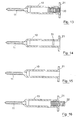
- the spacer section 10 may be provided with a threaded insert 30 [ Fig. 13 ] or may be adapted at 31 to receive a bayonet type fixing [ Fig. 14 ] or the fixing may be a push type [ Fig. 15 ], or the fixing may be a threaded stud 32 to accept a nut fastener [ Fig. 16 ]
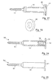
- the spacer section 10 has an external self sealing washer 40 as illustrated in Figs. 17 and 18 .
- the washer 40 may be of any suitable material such as of a flexible polymer material.
- the tapered end 20 of the spacer section 10 need not necessarily penetrate the sheathing 8.
- a frame fixing screw 51 is integral with the spacer section 10. This may be of the same material as the spacer section 10, be mechanically or adhesively connected to the spacer section 10 or moulded unto the spacer.
- the head 21 of the spacer section 10 may be of any suitable form and may have engagement features 60 to enable a tool to be located to grip the spacer 10 and preventing rotation during tightening of the bracket bolt 13.
- the assembly of the system involves pushing the hollow spacer section 10 through the insulation material 3. This can be done manually or be automated.
- a frame fixing screw 11 is then driven through the sheathing board 5 into the steel frame 2.
- a manufactured bracket 5 is then bolted to the flat head 21 of the spacer section 10 with a bolt 13.
- a number of the in-line brackets 5 are connected vertically with linear support element 7. The interface between the head 21 of the spacer section 10 and the bracket 5 acts as a moment resisting joint ensuring that load on the screw acts only in tension, compression and shear.
- the fixing and spacing element 6 supports a bracket 5 at the surface of the insulation. It may self penetrate the insulation layer or pre-formed holes may be provided. It also transfers loading to the frame 2 of the building.
- Thermal performance is improved as the fixing/spacing element 6 may be of stainless steel and has a small conductive cross sectional area. Because the fixing 6 is at least partially self penetrating and symmetrical on its central axis it is easy to use and assembly is readily automated. The joint has improved mechanical performance as moments are resisted ensuring that only shear and axial stresses are applied.
- the linear support element 7 may be of consistent cross section i.e. prismatic, or may vary in section along its length.
- the linear support element 7 may have an array of holes for connectivity or may be provided with other engagement features such as knurls, dogs, teeth and captive pins.
- the linear support element 7 may be of decorative nature to provide an architectural feature.
- the linear support element 7 may be formed from metal or polymer/reinforced polymer materials, or may be made from timber or other organic materials.
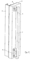
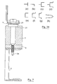
- the profile of the support element 7 can be of, but not limited to, the types shown in Fig. 34 .
- Figs. 34(a) to 34(h) illustrate various cross sectional profiles of the linear bracket connecting element 7 used in system of the invention.
- the sections illustrated in Figs. 34(a) to 34(d) are suitable for use with separate bracket elements.
- the brackets and support elements may be integral in a single unit.
- the sections illustrated in Figs. 34 (e) to 34(g) can be utilised to provide such integral brackets and connecting element.
- the design of the spacer element/fixing lends itself to various manufacturing methods. It may be cold formed from tube, turned from bar, cast in metal or injection moulded from polymer or reinforced polymer material. Sintering or moulding of ceramic or vitreous materials may also be used. These materials may be used to further reduce thermal conductivity.
Landscapes
- Engineering & Computer Science (AREA)
- Architecture (AREA)
- Civil Engineering (AREA)
- Structural Engineering (AREA)
- Finishing Walls (AREA)
- Building Environments (AREA)
- Joining Of Building Structures In Genera (AREA)
Description
- The invention relates to a support system for an exterior cladding system. In particular, the invention relates to a support for a rainscreen system.
- Generally, a cladding or rainscreen is applied to a building frame. In one known system, a rainscreen in the form of a façade panel or board and its supports is attached to a building frame by means of a number of brackets. The purpose of the brackets is to carry the load from the façade. The load can be due to the weight of the panel and/or wind pressure. In one arrangement the brackets are inserted through pre cut holes in the insulation layer. Screws are used to fix the brackets to the substrate beneath. The length of the brackets is varied, depending on the insulation thickness and cavity required. After fitting the pre-cut holes are refilled and sealed.
- There are a number of problems with conventional systems. The brackets provide a heat conductor which may adversely affect the thermal performance. The systems are also labour intensive and require an installer to carry out a number of steps for correct fitting and finishing.
- Current solutions for brackets are of either generally angular or cylindrical form. Angle brackets are typically of stainless steel or aluminium construction to resist corrosion and are provided with holes for installation to the substrate and a set of attachment features for the façade support grid. See for example
DE 203 17 103 U1 . - These brackets perform well structurally when fixed to a rigid substrate such as reinforced concrete or masonry. They can also be made to perform structurally adequately when fixed to timber and steel framing. Thermal performance is generally adequate when angle brackets are fastened to low conductivity substrates such as concrete and timber, but major and disproportionate heat losses can result when angle brackets are fixed to conductive materials such as steel. The insulation will also need to be cut and made good to insert the bracket. In façade applications where the cavity is freely ventilated and the façade may have open joints, it is important to be able to seal the weather resisting surface for air, water and vapour permeability. The fin projection of angle brackets is difficult to seal to membrane type barriers, and also to rigid faces that have been cut and made good. Seals applied tend to be mastic and wet applied polymer types, these have a limited life expectancy and are difficult to replace when the façade is in place. They are also very dependant on good initial workmanship in order to perform.
- Cylindrical type brackets tend to be used into concrete or masonry substrates and are fixed with threaded rod cores that anchor into the substrate by mechanical or adhesive means. They are generally dependant for their resistance to vertical loads on the bending strength of the threaded bar element and the shear strength of the substrate, i.e. the threaded rod element must act as a cantilever. In some cases the rod acts as a tension element, and the cylindrical covering element is clamped back to the substrate. In this case the system relies on the rigidity of the substrate for its resistance to overturning. Where the substrate is of limited depth and rigidity, e.g. thin steel, aluminium or soft wood. Some fasteners rely on their bearing onto rigid insulation materials, this substantially limits their load carrying capacity and possibly their long term durability and function.
- Thermally, the threaded rod element has a relatively large cross section for structural purposes where it acts as a cantilever: this is relatively unimportant where low conductivity substrates are concerned. Where the threaded element acts in tension, the covering element can be manufactured from low conductivity materials to give good thermal performance. Products that have small fixings and rely on the rigidity of insulation, or do not resist high vertical loads may be manufactured from low conductivity materials such as plastics for good thermal performance. These are generally used solely to install insulation materials and hold them in place.
- Cylindrical elements are intrinsically simpler to seal then plate/fin elements, and can easily incorporate a sealing washer into their design.
- This invention is directed towards providing a bracket with the capacity to carry relatively high vertical loads associated with the weight of façade cladding materials and horizontal wind loads, whilst minimising the thermal losses though the system when connected to a thermally conductive substrate or frame. This is combined with features to provide good leakage resistance performance to air, water and vapour, on a repeatable and easily attainable basis. The bracket provides versatility in its provision for mounting alternative materials and a variety of cavity sizes.
- According to the invention there is provided a support system for mounting building façade elements to a framework, according to
claim 1. - In one embodiment the frame fixing element extends from the spacer section. The frame fixing element may extend from one end of the spacer section and the spacer section comprises a flange at an opposite end.
- In one case the frame fixing element is a separate component from the spacer section. The frame fixing element may be movable relative to the spacer section. In another embodiment the frame fixing element is fixed relative to the spacer section.
- In another case the frame fixing element is integral with the spacer section.
- In one embodiment the spacer section is at least partially hollow. The spacer section may be engageable with the bracket fixing element. For example, the spacer section may screw threadingly engageable with the bracket fixing element.
- In one embodiment the frame fixing element is self penetrating through an insulation body.
- In one case the frame fixing element is self drilling and self tapping.
- In another embodiment the spacer section has a stiffening flange.
- The support system may have a washer which is engageable with the stiffening flange.
- In a further embodiment the brackets and the support element are integral in a single unit.
- The invention also provides a cladding system incorporating a support system of the invention.
- In another aspect the invention provides a cladding system according to claim 18.
- In the invention there is provided a support system comprising a number of bracket elements and spacer elements; the spacer elements comprising cylindrical spacer section, a frame fixing element and a bracket fixing element, the flanged bracket elements being interconnected by a linear support element.
- The invention also provides a rainscreen support system incorporating a support system of the invention.
- The invention will be more clearly understood from the following description thereof given by way of example only, in which:-
-
Fig. 1 is a cross sectional view of a rainscreen system incorporating a support system of the invention; -
Fig. 2 is a perspective view of part of the rainscreen system ofFig. 1 ; -
Fig. 3 is a cross sectional view of a detail of the rainscreen system and support system ofFig. 1 ; -
Fig. 4 is an cross sectional view of a fixing device of the system; -
Fig. 5 is a cross sectional view of a spacer part of the device ofFig. 4 ; -
Fig. 6 is an elevational view of the spacer ofFig. 5 ; -
Fig. 7 is a cross sectional view of an alternative detail of the rainscreen and support system with an alternative fixing; -
Fig. 8 is a perspective view of the fixing ofFig. 7 : -
Fig. 9 is a top plan view of the fixing ofFig. 8 : -
Fig. 10 is a side elevational view of the fixing; -
Fig. 11 is cross sectional view on the line XI - XI inFig. 9 : -
Fig. 12 is a perspective view of the fixing ofFigs. 7 to 11 with a washer in place; -
Figs. 13 to 16 are views of alternative fixing devices; -
Fig. 17 is a cross sectional view of another fixing device of the invention including a washer; -
Fig. 18 is a perspective view of the washer ofFig. 17 ; -
Fig. 19 is an exploded perspective view of a fixing device; -
Figs. 20 and 21 are force diagrams; -
Fig. 22 is a cross sectional view of an alternative rainscreen system; -
Fig. 23 is a cross sectional view of a detail of another rainscreen system; -
Figs. 24 and 25 are respectively cross sectional and elevational views of a fixing device used in the system ofFig. 23 ; -
Fig. 26 is a perspective view of the fixing device ofFigs. 24 and 25 ; -
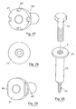
Figs. 27 to 29 are views of alternative heads of the fixing device ofFig. 13 ; -
Fig. 30 is a perspective view of a fixing device; -
Figs. 31 to 33 are views of alternative heads of the fixing device ofFig. 15 ; and -
Figs. 34(a) to 34(h) illustrate various cross sectional profiles of a linear connecting element used in the system of the invention. - Referring to the drawings and initially to
Figs. 1 to 6 there is illustrated a support system for mountingbuilding facade elements 1 to aframework 2. Aninsulation body 3 is attached to theframework 2 and a plurality ofbrackets 5 are used to interconnect theframework 2 and thefacade elements 2. A plurality of spacer elements orfixings 6 are used to mount thebrackets 5 to thesupport framework 2. In -line brackets 5 are interconnected by asupport element 7. Asheathing board 8 may be interposed between theframe 2 and theinsulation body 3. Thebrackets 5 may have slotted fixingholes 9 to facilitate thermal expansion - The fixing 6 comprises a generally
cylindrical spacer section 10 and a frame fixing element I in the form of a screw for fixing to aframe 2. Thespacer section 10 also defines areceiver 12 for reception of a bracket fixing 13 which may be in the form of a bolt. Thespacer section 10 may be screw threaded at 14 to receive a correspondingly threaded shank of thebolt 3. - The
spacer section 10 has afront end 20 which is tapered to facilitate penetration and embedding of thefront end 20 in theinsulation 3 andsheathing board 8 when thescrew 11 is driven. At the opposite end thespacer section 10 has a stiffeningflange 21 which acts as a land for thebracket 5, thebracket 5 being securely fixed to theflange 21 by thebolt 13. - In this case the
frame fixing screw 11 is a separate component which is extendable through ahole 22 in thetapered end 20 of thespacer section 10. The fixing 11 is self drilling and self tapping. Thescrew 11 may be adapted to suit theframe 2 for improved strength. - Referring to
Figs. 7 to 12 there is illustrated an alternative detail of the cladding and support system of the invention with analternative fixing system 23 which is similar to that described above and like parts are assigned the same reference numerals. In this case the frame fixing element is a self drilling andself tapping screw 24. Theframe fixing element 24 is held captive in thespacer section 10 for ease of use. Thespacer section 10 has ashoulder 25 and the frame fixing end of thespacer section 10 is turned inwardly at 26 to hold theframe fixing element 24. Rotation of theframe fixing element 24 is facilitated whilst retaining the fixing element for ease of use. An externalself sealing washer 27 is provided. The washer functions to create a water and air seal when the spacer is tightened into position. The seal is created between the spacer flange and the surface of the insulation. - As illustrated in
Fig. 19 thescrew 11 may have any type of suitable driving head. For ease of use the screw may be held at least partially captive at thetapered end 20. - The
spacer section 10 may be engagable in any suitable manner with thebracket fixing element 13. For example, thespacer section 10 may be provided with a threaded insert 30 [Fig. 13 ] or may be adapted at 31 to receive a bayonet type fixing [Fig. 14 ] or the fixing may be a push type [Fig. 15 ], or the fixing may be a threadedstud 32 to accept a nut fastener [Fig. 16 ] - Preferably the
spacer section 10 has an externalself sealing washer 40 as illustrated inFigs. 17 and 18 . Thewasher 40 may be of any suitable material such as of a flexible polymer material. - Referring to
Fig. 22 thetapered end 20 of thespacer section 10 need not necessarily penetrate thesheathing 8. - Referring to
Figs. 23 to 25 there is illustrated another fixing 50. In this case aframe fixing screw 51 is integral with thespacer section 10. This may be of the same material as thespacer section 10, be mechanically or adhesively connected to thespacer section 10 or moulded unto the spacer. - As illustrated in
Figs. 26 to 33 thehead 21 of thespacer section 10 may be of any suitable form and may have engagement features 60 to enable a tool to be located to grip thespacer 10 and preventing rotation during tightening of thebracket bolt 13. - The assembly of the system involves pushing the
hollow spacer section 10 through theinsulation material 3. This can be done manually or be automated. Aframe fixing screw 11 is then driven through thesheathing board 5 into thesteel frame 2. A manufacturedbracket 5 is then bolted to theflat head 21 of thespacer section 10 with abolt 13. A number of the in-line brackets 5 are connected vertically withlinear support element 7. The interface between thehead 21 of thespacer section 10 and thebracket 5 acts as a moment resisting joint ensuring that load on the screw acts only in tension, compression and shear. - Referring to
Fig. 20 in use of the fixing/spacing element loading L is applied downwardly on thebracket 5 due to gravity. This load is transmitted along thespacer element 10 to thescrew 11 which acts in a shear direction S. Rotational moments M1 and M2 are resisted by resistance to rotation from the bracket connection element 7 (R1) and (R2) [Fig. 21 ]. Wind load W acts along thespacer 6. - The fixing and
spacing element 6 supports abracket 5 at the surface of the insulation. It may self penetrate the insulation layer or pre-formed holes may be provided. It also transfers loading to theframe 2 of the building. - Thermal performance is improved as the fixing/
spacing element 6 may be of stainless steel and has a small conductive cross sectional area. Because the fixing 6 is at least partially self penetrating and symmetrical on its central axis it is easy to use and assembly is readily automated. The joint has improved mechanical performance as moments are resisted ensuring that only shear and axial stresses are applied. - The
linear support element 7 may be of consistent cross section i.e. prismatic, or may vary in section along its length. Thelinear support element 7 may have an array of holes for connectivity or may be provided with other engagement features such as knurls, dogs, teeth and captive pins. Thelinear support element 7 may be of decorative nature to provide an architectural feature. Thelinear support element 7 may be formed from metal or polymer/reinforced polymer materials, or may be made from timber or other organic materials. The profile of thesupport element 7 can be of, but not limited to, the types shown inFig. 34 . -
Figs. 34(a) to 34(h) illustrate various cross sectional profiles of the linearbracket connecting element 7 used in system of the invention. The sections illustrated inFigs. 34(a) to 34(d) are suitable for use with separate bracket elements. The brackets and support elements may be integral in a single unit. The sections illustrated inFigs. 34 (e) to 34(g) can be utilised to provide such integral brackets and connecting element. - The design of the spacer element/fixing lends itself to various manufacturing methods. It may be cold formed from tube, turned from bar, cast in metal or injection moulded from polymer or reinforced polymer material. Sintering or moulding of ceramic or vitreous materials may also be used. These materials may be used to further reduce thermal conductivity.
- Many variations on the embodiments described will be readily apparent. Accordingly the invention is not limited to the embodiments hereinbefore described which may be varied in detail.
Claims (19)
- A support system for mounting building facade elements to a framework, the support system comprising:-a plurality of spaced-apart brackets;a plurality of fixings for mounting the brackets to a framework,the fixing comprising a generally cylindrical spacer section having a frame end and a bracket end, the spacer section having a flange at the bracket end,a frame fixing element extending from the frame end of the spacer section for fixing to a framework and a bracket fixing element for extending from the bracket end of the spacer section for fixing to the bracket; anda facade support element fixedly interconnecting in-line brackets.
- A support system as claimed in claim 1 wherein the frame fixing element is a separate component from the spacer section.
- A support system as claimed in claim 2 wherein the frame fixing element is held captive in the spacer section.
- A support system as claimed in claim 2 or 3 wherein the frame fixing element is rotatably movable relative to the spacer section.
- A support system as claimed in claim 2 wherein the frame fixing element is fixed relative to the spacer section.
- A support system as claimed in claim 1 wherein the frame fixing element is integral with the spacer section.
- A support system as claimed in any of claims 1 to 6 wherein the spacer section is at least partially hollow.
- A support system as claimed in claim 7 wherein the spacer section is engagable with the bracket fixing element.
- A support system as claimed in claim 8 wherein the spacer section is screw threadingly engagable with the bracket fixing element.
- A support system as claimed in any of claims 1 to 9 wherein the spacer section has a small conductive cross sectional area.
- A support system as claimed in any of claims I to 10 wherein the spacer section is of stainless steel.
- A support system as claimed in any of claims 1 to 10 wherein the spacer section is of a polymer material, a reinforced polymer material, a ceramic material, or a vitreous material.
- A support system as claimed in any of claims 1 to 12 wherein the frame fixing element is self penetrating through an insulation body.
- A support system as claimed in any of claims I to 13 wherein the frame fixing element is self drilling and self tapping.
- A support system as claimed in any of claims 1 to 14 comprising a washer which is engageable with the flange.
- A support system as claimed in claim 15 wherein the washer is an external self sealing washer.
- A support system as claimed in claim 1 wherein the brackets and the support element are integral in a single unit.
- A cladding system incorporating a support system as claimed in any preceding claim.
- A cladding system comprising:-a support framework;an insulation body attached to the framework;a plurality of spaced - apart brackets;a support system as claimed in any of claims 1 to 19; andfacade elements mounted to the support element.
Priority Applications (1)
| Application Number | Priority Date | Filing Date | Title |
|---|---|---|---|
| PL08751341T PL2145060T3 (en) | 2007-05-17 | 2008-05-16 | A support system for mounting building facade elements to a framework |
Applications Claiming Priority (2)
| Application Number | Priority Date | Filing Date | Title |
|---|---|---|---|
| IE20070358 | 2007-05-17 | ||
| PCT/IE2008/000058 WO2008142667A1 (en) | 2007-05-17 | 2008-05-16 | A support system for mounting building facade elements to a framework |
Publications (2)
| Publication Number | Publication Date |
|---|---|
| EP2145060A1 EP2145060A1 (en) | 2010-01-20 |
| EP2145060B1 true EP2145060B1 (en) | 2014-02-12 |
Family
ID=39596038
Family Applications (1)
| Application Number | Title | Priority Date | Filing Date |
|---|---|---|---|
| EP08751341.2A Active EP2145060B1 (en) | 2007-05-17 | 2008-05-16 | A support system for mounting building facade elements to a framework |
Country Status (10)
| Country | Link |
|---|---|
| US (1) | US20100199585A1 (en) |
| EP (1) | EP2145060B1 (en) |
| AU (1) | AU2008252394B2 (en) |
| CA (1) | CA2683279A1 (en) |
| ES (1) | ES2452832T3 (en) |
| GB (1) | GB2449360B (en) |
| IE (1) | IE86153B1 (en) |
| PL (1) | PL2145060T3 (en) |
| WO (1) | WO2008142667A1 (en) |
| ZA (1) | ZA200907600B (en) |
Cited By (1)
| Publication number | Priority date | Publication date | Assignee | Title |
|---|---|---|---|---|
| US10011418B2 (en) | 2014-09-26 | 2018-07-03 | Pelican Biothermal Llc | High efficiency bolt-on thermal insulating panel and thermally insulated shipping container employing such a thermal insulating panel |
Families Citing this family (23)
| Publication number | Priority date | Publication date | Assignee | Title |
|---|---|---|---|---|
| DE102010061244A1 (en) * | 2010-02-05 | 2011-08-11 | fischerwerke GmbH & Co. KG, 72178 | Fastening arrangement, scaffolding and fixing anchor for this |
| USD666894S1 (en) | 2011-04-15 | 2012-09-11 | Cascadia Windows, Ltd. | Girt spacer |
| DE202011100848U1 (en) * | 2011-05-18 | 2011-08-03 | Henning Gmbh & Co. Kg | Scaffold anchoring device |
| GB2497796A (en) * | 2011-12-21 | 2013-06-26 | Hardie James Technology Ltd | Thermally Efficient Façade |
| CA2763058C (en) | 2012-01-05 | 2014-10-14 | Cascadia Windows Ltd. | Thermally insulative spacer and methods involving use of same |
| CA2784018C (en) * | 2012-07-26 | 2019-12-24 | Engineered Assemblies Inc. | Thermal clip system and apparatus for a building wall assembly |
| US8919070B2 (en) | 2012-08-30 | 2014-12-30 | Technoform Holding GmbH | Spacer for retaining cladding element on structural building element |
| FR2995928B1 (en) * | 2012-09-26 | 2014-10-31 | Iso Ouest | DEVICE FOR FIXING A COMPLEX INSULATING MATERIAL ON A SUPPORT |
| US9140007B2 (en) | 2013-04-23 | 2015-09-22 | MOTO Extrusions, Inc. | Rain screen framing system |
| US9140008B2 (en) | 2013-04-23 | 2015-09-22 | MOTO Extrusions, Inc. | Multi-layered cladding frame system |
| US9493941B2 (en) * | 2013-05-02 | 2016-11-15 | Donald George White | Thermal break wall systems and thermal adjustable clip |
| CN104328881B (en) * | 2014-03-14 | 2015-05-13 | 建研科技股份有限公司 | Vacuum insulation panel heat-preservation decoration dry hanging system and construction method thereof |
| FR3018837A1 (en) * | 2014-03-21 | 2015-09-25 | Gen Innovation Ind France | PANEL CONNECTOR EXTERIOR TO A FRAMEWORK |
| US20170020287A1 (en) * | 2015-04-24 | 2017-01-26 | Qtran, Inc. | Support bracket system |
| DE102015220120B4 (en) * | 2015-10-15 | 2017-05-18 | Manfred Lutz | Spacing device for attaching a load to a supporting structure of a building |
| CZ2018129A3 (en) * | 2018-03-14 | 2019-05-15 | IzoDol s.r.o. | Anchoring for producing a shaped facade, shaped facade and method of producing a shaped facade |
| EP3686370A1 (en) | 2019-01-25 | 2020-07-29 | Pittsburgh Corning Europe NV | Façade cladding fixing system |
| CA3075824C (en) * | 2019-03-15 | 2024-05-14 | Invent To Build Inc. | Thermally separated composite panel assembly |
| US11566421B2 (en) | 2020-06-25 | 2023-01-31 | Advanced Architectural Products, Llc | Adjustable support system for a building structure and a wall structure having an adjustable support system |
| US11542702B2 (en) | 2020-06-25 | 2023-01-03 | Advanced Architectural Products, Llc | Adjustable support system for a building structure and a wall structure having an adjustable support system |
| US11459769B2 (en) * | 2020-09-02 | 2022-10-04 | Eutoplus Co., Ltd | Brick panel assembly system |
| US20230048980A1 (en) * | 2021-08-12 | 2023-02-16 | James Tiner | Stack-It Bracket |
| GB2700096A (en) * | 2023-12-15 | 2025-09-24 | Autex Industries Ltd | Fixing of pet panels to allow for recycling |
Family Cites Families (23)
| Publication number | Priority date | Publication date | Assignee | Title |
|---|---|---|---|---|
| US4455801A (en) * | 1982-07-29 | 1984-06-26 | Canadian Patents & Development Limited | Light weight vault wall |
| GB8507191D0 (en) * | 1985-03-20 | 1985-04-24 | Cladcolor Profiling Ltd | Support system |
| CA1296502C (en) * | 1988-06-13 | 1992-03-03 | William F. Dempsey | Fascia panel structures |
| DE4342748A1 (en) * | 1993-12-15 | 1995-06-22 | Fischer Artur Werke Gmbh | Fastening system for facade panels |
| AUPO215996A0 (en) * | 1996-09-05 | 1996-10-03 | James Hardie International Finance B.V. | An improved cladding board mounting system |
| US6167664B1 (en) * | 1997-05-28 | 2001-01-02 | Knoll, Inc. | Hybrid office panel construction for a modular office furniture system |
| EP0919674A1 (en) * | 1997-11-28 | 1999-06-02 | Willy Trittenbach | Supporting element |
| DK0921252T3 (en) * | 1997-12-02 | 2006-04-03 | Sfs Intec Holding Ag | Fixing element for spacer attachment of profiles, profiles, plates and the like |
| CH693798A5 (en) * | 1999-05-03 | 2004-02-13 | Reto Demont | Method of anchoring rear ventilated cladding on wall involves attaching support bridges directly through the insulation |
| DE29912412U1 (en) * | 1999-07-15 | 1999-11-25 | Haase, Walter, Dipl.-Ing., 22941 Jersbek | Bracket for ventilated building cladding |
| US6945001B1 (en) * | 2000-05-01 | 2005-09-20 | Masao Suzuki | Building using external facing material for construction |
| DE10141308C1 (en) * | 2001-08-28 | 2002-10-31 | Wilhelm Nauth | Fastening system for facade element on building has screw on horizontal slider engaging in facade plate and includes horizontal rail on vertical support |
| ATE318970T1 (en) * | 2002-01-30 | 2006-03-15 | Architectural Profiles Ltd | FAIRING |
| DE10205623B4 (en) * | 2002-02-12 | 2004-04-22 | Wendker Fassaden-Systembau Gmbh | Fastening system for small format wall elements on building walls |
| DE20320430U1 (en) * | 2002-07-24 | 2004-12-02 | Albert Hangleiter Gmbh & Co. Kg | Fastener for securing vacuum insulating panels has a flexible film linking two grip flanges and with attached wall mounting grip |
| CH696546A5 (en) * | 2003-04-10 | 2007-07-31 | Reto Demont | Fastening element for fastening on building of insulating course and ventilated protective layer, has metal shaft inserted from outside into insulating course and with first and second load application elements on respective ends |
| US7021876B2 (en) * | 2003-08-28 | 2006-04-04 | Bulent Gulistan | Simplified installation captive panel fastener |
| US6815650B1 (en) * | 2004-01-02 | 2004-11-09 | Kathleen M. Bartz | Energization cycle counter for induction heating tool |
| WO2005088024A1 (en) * | 2004-03-11 | 2005-09-22 | Harald Zahn Gmbh | Sealing plate for a fixing element, fixing element formed thereby, and auxiliary assembly device therefor |
| ATE433023T1 (en) * | 2004-04-28 | 2009-06-15 | Ranit Befestigungssysteme Gmbh | FASTENING SYSTEM FOR COMPONENTS ON A WALL |
| DE202006003142U1 (en) * | 2006-03-01 | 2006-05-24 | Schmidt, Werner | Bounce back wall for sports hall, has anchor for supporting spring unit and section guided directly or indirectly on anchor in relocatable manner, where spring unit, section and anchor are made from non-combustible manner e.g. steel |
| CA2661259A1 (en) * | 2008-04-01 | 2009-10-01 | Firestone Diversified Products, Llc | Wall panel system with snap clip |
| US20090313935A1 (en) * | 2008-06-24 | 2009-12-24 | Environmental Interiors, Inc. | High Impact, Moisture Resistant Wall Panel System |
-
2008
- 2008-05-16 IE IE20080388A patent/IE86153B1/en not_active IP Right Cessation
- 2008-05-16 ES ES08751341.2T patent/ES2452832T3/en active Active
- 2008-05-16 EP EP08751341.2A patent/EP2145060B1/en active Active
- 2008-05-16 GB GB0808963.3A patent/GB2449360B/en not_active Expired - Fee Related
- 2008-05-16 US US12/451,391 patent/US20100199585A1/en not_active Abandoned
- 2008-05-16 PL PL08751341T patent/PL2145060T3/en unknown
- 2008-05-16 CA CA2683279A patent/CA2683279A1/en not_active Abandoned
- 2008-05-16 AU AU2008252394A patent/AU2008252394B2/en active Active
- 2008-05-16 WO PCT/IE2008/000058 patent/WO2008142667A1/en not_active Ceased
-
2009
- 2009-10-29 ZA ZA200907600A patent/ZA200907600B/en unknown
Cited By (1)
| Publication number | Priority date | Publication date | Assignee | Title |
|---|---|---|---|---|
| US10011418B2 (en) | 2014-09-26 | 2018-07-03 | Pelican Biothermal Llc | High efficiency bolt-on thermal insulating panel and thermally insulated shipping container employing such a thermal insulating panel |
Also Published As
| Publication number | Publication date |
|---|---|
| WO2008142667A8 (en) | 2009-12-03 |
| CA2683279A1 (en) | 2008-11-27 |
| IE20080388A1 (en) | 2009-06-24 |
| GB0808963D0 (en) | 2008-06-25 |
| EP2145060A1 (en) | 2010-01-20 |
| PL2145060T3 (en) | 2014-05-30 |
| ZA200907600B (en) | 2010-07-28 |
| GB2449360B (en) | 2012-06-06 |
| AU2008252394B2 (en) | 2014-10-23 |
| IE86153B1 (en) | 2013-03-13 |
| GB2449360A (en) | 2008-11-19 |
| ES2452832T3 (en) | 2014-04-02 |
| AU2008252394A1 (en) | 2008-11-27 |
| WO2008142667A1 (en) | 2008-11-27 |
| US20100199585A1 (en) | 2010-08-12 |
Similar Documents
| Publication | Publication Date | Title |
|---|---|---|
| AU2008252394B2 (en) | A support system for mounting building facade elements to a framework | |
| EP2800846B1 (en) | A facade system | |
| US9995333B2 (en) | Devices, systems, and methods for securing a component to a surface | |
| JP7847613B2 (en) | Anchor and fastener combination assembly | |
| US20070094955A1 (en) | Sectional construction assemblies | |
| JP2011226095A (en) | Post-construction anchor for foundation | |
| US20130164096A1 (en) | Fastening device on a building | |
| CN215367891U (en) | Aerogel composite inorganic foam external thermal insulation system | |
| CN215166714U (en) | Heat preservation outer wall and reinforced structure thereof | |
| EP2449185B1 (en) | Supplementary insulation system and a method for insulating a façade | |
| JP4005975B2 (en) | Exterior wall panel mounting hardware for buildings using the exterior insulation method | |
| CN217420160U (en) | Steel constructs and pierces through glass unitized curtain wall system | |
| CN216974023U (en) | Switching subassembly and hang brick system | |
| CN217580675U (en) | A mounting structure and wall body structure behind moulding for keeping warm and structure integration building facade | |
| CN221073073U (en) | Connecting structure of preset screw rod type steel column and rock wool board external heat preservation system | |
| CN214272765U (en) | Keel structure of hanging plate | |
| AU2026201285A1 (en) | Veneer and fixing system | |
| CA2815508A1 (en) | Sealing anchor and anchoring system for insulated panel walls | |
| CN223661250U (en) | An exterior wall insulation and decorative panel system | |
| EP4741599A1 (en) | Fastening bracket | |
| CN211973883U (en) | External wall protection heat-proof device | |
| FI108364B (en) | Fastening band for laminated body | |
| CN118128257A (en) | A thermal insulation bridge structure and construction method for steel tube concrete column | |
| JP2004027804A (en) | Exterior support member and its mounting method | |
| JP3403943B2 (en) | Outer insulation outer wall structure |
Legal Events
| Date | Code | Title | Description |
|---|---|---|---|
| PUAI | Public reference made under article 153(3) epc to a published international application that has entered the european phase |
Free format text: ORIGINAL CODE: 0009012 |
|
| 17P | Request for examination filed |
Effective date: 20091027 |
|
| AK | Designated contracting states |
Kind code of ref document: A1 Designated state(s): AT BE BG CH CY CZ DE DK EE ES FI FR GB GR HR HU IE IS IT LI LT LU LV MC MT NL NO PL PT RO SE SI SK TR |
|
| AX | Request for extension of the european patent |
Extension state: AL BA MK RS |
|
| GRAP | Despatch of communication of intention to grant a patent |
Free format text: ORIGINAL CODE: EPIDOSNIGR1 |
|
| INTG | Intention to grant announced |
Effective date: 20130909 |
|
| RIN1 | Information on inventor provided before grant (corrected) |
Inventor name: GARNER, LEO Inventor name: STEVENS, MARK, VICTOR |
|
| GRAS | Grant fee paid |
Free format text: ORIGINAL CODE: EPIDOSNIGR3 |
|
| GRAA | (expected) grant |
Free format text: ORIGINAL CODE: 0009210 |
|
| AK | Designated contracting states |
Kind code of ref document: B1 Designated state(s): AT BE BG CH CY CZ DE DK EE ES FI FR GB GR HR HU IE IS IT LI LT LU LV MC MT NL NO PL PT RO SE SI SK TR |
|
| AX | Request for extension of the european patent |
Extension state: AL BA MK RS |
|
| REG | Reference to a national code |
Ref country code: GB Ref legal event code: FG4D |
|
| REG | Reference to a national code |
Ref country code: CH Ref legal event code: EP |
|
| REG | Reference to a national code |
Ref country code: AT Ref legal event code: REF Ref document number: 652249 Country of ref document: AT Kind code of ref document: T Effective date: 20140215 |
|
| REG | Reference to a national code |
Ref country code: IE Ref legal event code: FG4D |
|
| REG | Reference to a national code |
Ref country code: DE Ref legal event code: R096 Ref document number: 602008030254 Country of ref document: DE Effective date: 20140327 |
|
| REG | Reference to a national code |
Ref country code: ES Ref legal event code: FG2A Ref document number: 2452832 Country of ref document: ES Kind code of ref document: T3 Effective date: 20140402 |
|
| REG | Reference to a national code |
Ref country code: NL Ref legal event code: T3 |
|
| REG | Reference to a national code |
Ref country code: PL Ref legal event code: T3 |
|
| REG | Reference to a national code |
Ref country code: AT Ref legal event code: MK05 Ref document number: 652249 Country of ref document: AT Kind code of ref document: T Effective date: 20140212 |
|
| REG | Reference to a national code |
Ref country code: LT Ref legal event code: MG4D |
|
| PG25 | Lapsed in a contracting state [announced via postgrant information from national office to epo] |
Ref country code: NO Free format text: LAPSE BECAUSE OF FAILURE TO SUBMIT A TRANSLATION OF THE DESCRIPTION OR TO PAY THE FEE WITHIN THE PRESCRIBED TIME-LIMIT Effective date: 20140512 Ref country code: LT Free format text: LAPSE BECAUSE OF FAILURE TO SUBMIT A TRANSLATION OF THE DESCRIPTION OR TO PAY THE FEE WITHIN THE PRESCRIBED TIME-LIMIT Effective date: 20140212 Ref country code: IS Free format text: LAPSE BECAUSE OF FAILURE TO SUBMIT A TRANSLATION OF THE DESCRIPTION OR TO PAY THE FEE WITHIN THE PRESCRIBED TIME-LIMIT Effective date: 20140612 |
|
| PG25 | Lapsed in a contracting state [announced via postgrant information from national office to epo] |
Ref country code: FI Free format text: LAPSE BECAUSE OF FAILURE TO SUBMIT A TRANSLATION OF THE DESCRIPTION OR TO PAY THE FEE WITHIN THE PRESCRIBED TIME-LIMIT Effective date: 20140212 Ref country code: PT Free format text: LAPSE BECAUSE OF FAILURE TO SUBMIT A TRANSLATION OF THE DESCRIPTION OR TO PAY THE FEE WITHIN THE PRESCRIBED TIME-LIMIT Effective date: 20140612 Ref country code: SE Free format text: LAPSE BECAUSE OF FAILURE TO SUBMIT A TRANSLATION OF THE DESCRIPTION OR TO PAY THE FEE WITHIN THE PRESCRIBED TIME-LIMIT Effective date: 20140212 Ref country code: AT Free format text: LAPSE BECAUSE OF FAILURE TO SUBMIT A TRANSLATION OF THE DESCRIPTION OR TO PAY THE FEE WITHIN THE PRESCRIBED TIME-LIMIT Effective date: 20140212 Ref country code: CY Free format text: LAPSE BECAUSE OF FAILURE TO SUBMIT A TRANSLATION OF THE DESCRIPTION OR TO PAY THE FEE WITHIN THE PRESCRIBED TIME-LIMIT Effective date: 20140212 |
|
| PG25 | Lapsed in a contracting state [announced via postgrant information from national office to epo] |
Ref country code: LV Free format text: LAPSE BECAUSE OF FAILURE TO SUBMIT A TRANSLATION OF THE DESCRIPTION OR TO PAY THE FEE WITHIN THE PRESCRIBED TIME-LIMIT Effective date: 20140212 Ref country code: HR Free format text: LAPSE BECAUSE OF FAILURE TO SUBMIT A TRANSLATION OF THE DESCRIPTION OR TO PAY THE FEE WITHIN THE PRESCRIBED TIME-LIMIT Effective date: 20140212 Ref country code: BE Free format text: LAPSE BECAUSE OF FAILURE TO SUBMIT A TRANSLATION OF THE DESCRIPTION OR TO PAY THE FEE WITHIN THE PRESCRIBED TIME-LIMIT Effective date: 20140212 |
|
| PG25 | Lapsed in a contracting state [announced via postgrant information from national office to epo] |
Ref country code: RO Free format text: LAPSE BECAUSE OF FAILURE TO SUBMIT A TRANSLATION OF THE DESCRIPTION OR TO PAY THE FEE WITHIN THE PRESCRIBED TIME-LIMIT Effective date: 20140212 Ref country code: EE Free format text: LAPSE BECAUSE OF FAILURE TO SUBMIT A TRANSLATION OF THE DESCRIPTION OR TO PAY THE FEE WITHIN THE PRESCRIBED TIME-LIMIT Effective date: 20140212 Ref country code: CZ Free format text: LAPSE BECAUSE OF FAILURE TO SUBMIT A TRANSLATION OF THE DESCRIPTION OR TO PAY THE FEE WITHIN THE PRESCRIBED TIME-LIMIT Effective date: 20140212 Ref country code: DK Free format text: LAPSE BECAUSE OF FAILURE TO SUBMIT A TRANSLATION OF THE DESCRIPTION OR TO PAY THE FEE WITHIN THE PRESCRIBED TIME-LIMIT Effective date: 20140212 |
|
| REG | Reference to a national code |
Ref country code: DE Ref legal event code: R097 Ref document number: 602008030254 Country of ref document: DE |
|
| PG25 | Lapsed in a contracting state [announced via postgrant information from national office to epo] |
Ref country code: SK Free format text: LAPSE BECAUSE OF FAILURE TO SUBMIT A TRANSLATION OF THE DESCRIPTION OR TO PAY THE FEE WITHIN THE PRESCRIBED TIME-LIMIT Effective date: 20140212 |
|
| PLBE | No opposition filed within time limit |
Free format text: ORIGINAL CODE: 0009261 |
|
| STAA | Information on the status of an ep patent application or granted ep patent |
Free format text: STATUS: NO OPPOSITION FILED WITHIN TIME LIMIT |
|
| PG25 | Lapsed in a contracting state [announced via postgrant information from national office to epo] |
Ref country code: LU Free format text: LAPSE BECAUSE OF FAILURE TO SUBMIT A TRANSLATION OF THE DESCRIPTION OR TO PAY THE FEE WITHIN THE PRESCRIBED TIME-LIMIT Effective date: 20140516 |
|
| REG | Reference to a national code |
Ref country code: CH Ref legal event code: PL |
|
| 26N | No opposition filed |
Effective date: 20141113 |
|
| PG25 | Lapsed in a contracting state [announced via postgrant information from national office to epo] |
Ref country code: LI Free format text: LAPSE BECAUSE OF NON-PAYMENT OF DUE FEES Effective date: 20140531 Ref country code: CH Free format text: LAPSE BECAUSE OF NON-PAYMENT OF DUE FEES Effective date: 20140531 Ref country code: MC Free format text: LAPSE BECAUSE OF FAILURE TO SUBMIT A TRANSLATION OF THE DESCRIPTION OR TO PAY THE FEE WITHIN THE PRESCRIBED TIME-LIMIT Effective date: 20140212 |
|
| REG | Reference to a national code |
Ref country code: DE Ref legal event code: R097 Ref document number: 602008030254 Country of ref document: DE Effective date: 20141113 |
|
| PG25 | Lapsed in a contracting state [announced via postgrant information from national office to epo] |
Ref country code: IT Free format text: LAPSE BECAUSE OF FAILURE TO SUBMIT A TRANSLATION OF THE DESCRIPTION OR TO PAY THE FEE WITHIN THE PRESCRIBED TIME-LIMIT Effective date: 20140212 |
|
| PGFP | Annual fee paid to national office [announced via postgrant information from national office to epo] |
Ref country code: IE Payment date: 20150306 Year of fee payment: 8 |
|
| PG25 | Lapsed in a contracting state [announced via postgrant information from national office to epo] |
Ref country code: SI Free format text: LAPSE BECAUSE OF FAILURE TO SUBMIT A TRANSLATION OF THE DESCRIPTION OR TO PAY THE FEE WITHIN THE PRESCRIBED TIME-LIMIT Effective date: 20140212 |
|
| REG | Reference to a national code |
Ref country code: FR Ref legal event code: PLFP Year of fee payment: 8 |
|
| PGFP | Annual fee paid to national office [announced via postgrant information from national office to epo] |
Ref country code: ES Payment date: 20150622 Year of fee payment: 8 |
|
| PGFP | Annual fee paid to national office [announced via postgrant information from national office to epo] |
Ref country code: FR Payment date: 20150529 Year of fee payment: 8 Ref country code: NL Payment date: 20150526 Year of fee payment: 8 |
|
| PGFP | Annual fee paid to national office [announced via postgrant information from national office to epo] |
Ref country code: DE Payment date: 20150730 Year of fee payment: 8 |
|
| PG25 | Lapsed in a contracting state [announced via postgrant information from national office to epo] |
Ref country code: MT Free format text: LAPSE BECAUSE OF FAILURE TO SUBMIT A TRANSLATION OF THE DESCRIPTION OR TO PAY THE FEE WITHIN THE PRESCRIBED TIME-LIMIT Effective date: 20140212 |
|
| PG25 | Lapsed in a contracting state [announced via postgrant information from national office to epo] |
Ref country code: BG Free format text: LAPSE BECAUSE OF FAILURE TO SUBMIT A TRANSLATION OF THE DESCRIPTION OR TO PAY THE FEE WITHIN THE PRESCRIBED TIME-LIMIT Effective date: 20140212 |
|
| PG25 | Lapsed in a contracting state [announced via postgrant information from national office to epo] |
Ref country code: GR Free format text: LAPSE BECAUSE OF FAILURE TO SUBMIT A TRANSLATION OF THE DESCRIPTION OR TO PAY THE FEE WITHIN THE PRESCRIBED TIME-LIMIT Effective date: 20140513 |
|
| PG25 | Lapsed in a contracting state [announced via postgrant information from national office to epo] |
Ref country code: HU Free format text: LAPSE BECAUSE OF FAILURE TO SUBMIT A TRANSLATION OF THE DESCRIPTION OR TO PAY THE FEE WITHIN THE PRESCRIBED TIME-LIMIT; INVALID AB INITIO Effective date: 20080516 Ref country code: TR Free format text: LAPSE BECAUSE OF FAILURE TO SUBMIT A TRANSLATION OF THE DESCRIPTION OR TO PAY THE FEE WITHIN THE PRESCRIBED TIME-LIMIT Effective date: 20140212 |
|
| REG | Reference to a national code |
Ref country code: DE Ref legal event code: R119 Ref document number: 602008030254 Country of ref document: DE |
|
| REG | Reference to a national code |
Ref country code: NL Ref legal event code: MM Effective date: 20160601 |
|
| REG | Reference to a national code |
Ref country code: IE Ref legal event code: MM4A |
|
| PG25 | Lapsed in a contracting state [announced via postgrant information from national office to epo] |
Ref country code: NL Free format text: LAPSE BECAUSE OF NON-PAYMENT OF DUE FEES Effective date: 20160601 |
|
| REG | Reference to a national code |
Ref country code: FR Ref legal event code: ST Effective date: 20170131 |
|
| PG25 | Lapsed in a contracting state [announced via postgrant information from national office to epo] |
Ref country code: DE Free format text: LAPSE BECAUSE OF NON-PAYMENT OF DUE FEES Effective date: 20161201 Ref country code: FR Free format text: LAPSE BECAUSE OF NON-PAYMENT OF DUE FEES Effective date: 20160531 |
|
| PG25 | Lapsed in a contracting state [announced via postgrant information from national office to epo] |
Ref country code: IE Free format text: LAPSE BECAUSE OF NON-PAYMENT OF DUE FEES Effective date: 20160516 |
|
| PG25 | Lapsed in a contracting state [announced via postgrant information from national office to epo] |
Ref country code: ES Free format text: LAPSE BECAUSE OF NON-PAYMENT OF DUE FEES Effective date: 20160517 |
|
| REG | Reference to a national code |
Ref country code: ES Ref legal event code: FD2A Effective date: 20181204 |
|
| PGFP | Annual fee paid to national office [announced via postgrant information from national office to epo] |
Ref country code: PL Payment date: 20230418 Year of fee payment: 16 |
|
| PGFP | Annual fee paid to national office [announced via postgrant information from national office to epo] |
Ref country code: GB Payment date: 20230405 Year of fee payment: 16 |
|
| GBPC | Gb: european patent ceased through non-payment of renewal fee |
Effective date: 20240516 |
|
| PG25 | Lapsed in a contracting state [announced via postgrant information from national office to epo] |
Ref country code: GB Free format text: LAPSE BECAUSE OF NON-PAYMENT OF DUE FEES Effective date: 20240516 |
|
| PG25 | Lapsed in a contracting state [announced via postgrant information from national office to epo] |
Ref country code: PL Free format text: LAPSE BECAUSE OF NON-PAYMENT OF DUE FEES Effective date: 20240516 |