EP2144346A1 - Interactive electric power demand limiting scheme - Google Patents
Interactive electric power demand limiting scheme Download PDFInfo
- Publication number
- EP2144346A1 EP2144346A1 EP20080172212 EP08172212A EP2144346A1 EP 2144346 A1 EP2144346 A1 EP 2144346A1 EP 20080172212 EP20080172212 EP 20080172212 EP 08172212 A EP08172212 A EP 08172212A EP 2144346 A1 EP2144346 A1 EP 2144346A1
- Authority
- EP
- European Patent Office
- Prior art keywords
- power
- power switch
- controller
- demand
- closing
- Prior art date
- Legal status (The legal status is an assumption and is not a legal conclusion. Google has not performed a legal analysis and makes no representation as to the accuracy of the status listed.)
- Granted
Links
Images


Classifications
-
- H—ELECTRICITY
- H02—GENERATION; CONVERSION OR DISTRIBUTION OF ELECTRIC POWER
- H02J—ELECTRIC POWER NETWORKS; CIRCUIT ARRANGEMENTS OR SYSTEMS FOR SUPPLYING OR DISTRIBUTING ELECTRIC POWER; SYSTEMS FOR STORING ELECTRIC ENERGY
- H02J13/00—Circuit arrangements for providing remote monitoring or remote control of equipment in a power distribution network
- H02J13/13—Circuit arrangements for providing remote monitoring or remote control of equipment in a power distribution network characterised by the transmission of data to equipment in the power network
-
- H—ELECTRICITY
- H02—GENERATION; CONVERSION OR DISTRIBUTION OF ELECTRIC POWER
- H02J—ELECTRIC POWER NETWORKS; CIRCUIT ARRANGEMENTS OR SYSTEMS FOR SUPPLYING OR DISTRIBUTING ELECTRIC POWER; SYSTEMS FOR STORING ELECTRIC ENERGY
- H02J3/00—Circuit arrangements for AC mains or AC distribution networks
- H02J3/17—Demand-responsive operation of AC power transmission or distribution networks
-
- H—ELECTRICITY
- H02—GENERATION; CONVERSION OR DISTRIBUTION OF ELECTRIC POWER
- H02J—ELECTRIC POWER NETWORKS; CIRCUIT ARRANGEMENTS OR SYSTEMS FOR SUPPLYING OR DISTRIBUTING ELECTRIC POWER; SYSTEMS FOR STORING ELECTRIC ENERGY
- H02J2105/00—Networks for supplying or distributing electric power characterised by their spatial reach or by the load
- H02J2105/50—Networks for supplying or distributing electric power characterised by their spatial reach or by the load for selectively controlling the operation of the loads
- H02J2105/52—Networks for supplying or distributing electric power characterised by their spatial reach or by the load for selectively controlling the operation of the loads for limitation of the power consumption in the networks or in one section of the networks, e.g. load shedding or peak shaving
-
- Y—GENERAL TAGGING OF NEW TECHNOLOGICAL DEVELOPMENTS; GENERAL TAGGING OF CROSS-SECTIONAL TECHNOLOGIES SPANNING OVER SEVERAL SECTIONS OF THE IPC; TECHNICAL SUBJECTS COVERED BY FORMER USPC CROSS-REFERENCE ART COLLECTIONS [XRACs] AND DIGESTS
- Y02—TECHNOLOGIES OR APPLICATIONS FOR MITIGATION OR ADAPTATION AGAINST CLIMATE CHANGE
- Y02B—CLIMATE CHANGE MITIGATION TECHNOLOGIES RELATED TO BUILDINGS, e.g. HOUSING, HOUSE APPLIANCES OR RELATED END-USER APPLICATIONS
- Y02B70/00—Technologies for an efficient end-user side electric power management and consumption
- Y02B70/30—Systems integrating technologies related to power network operation and communication or information technologies for improving the carbon footprint of the management of residential or tertiary loads, i.e. smart grids as climate change mitigation technology in the buildings sector, including also the last stages of power distribution and the control, monitoring or operating management systems at local level
- Y02B70/3225—Demand response systems, e.g. load shedding, peak shaving
-
- Y—GENERAL TAGGING OF NEW TECHNOLOGICAL DEVELOPMENTS; GENERAL TAGGING OF CROSS-SECTIONAL TECHNOLOGIES SPANNING OVER SEVERAL SECTIONS OF THE IPC; TECHNICAL SUBJECTS COVERED BY FORMER USPC CROSS-REFERENCE ART COLLECTIONS [XRACs] AND DIGESTS
- Y04—INFORMATION OR COMMUNICATION TECHNOLOGIES HAVING AN IMPACT ON OTHER TECHNOLOGY AREAS
- Y04S—SYSTEMS INTEGRATING TECHNOLOGIES RELATED TO POWER NETWORK OPERATION, COMMUNICATION OR INFORMATION TECHNOLOGIES FOR IMPROVING THE ELECTRICAL POWER GENERATION, TRANSMISSION, DISTRIBUTION, MANAGEMENT OR USAGE, i.e. SMART GRIDS
- Y04S20/00—Management or operation of end-user stationary applications or the last stages of power distribution; Controlling, monitoring or operating thereof
- Y04S20/20—End-user application control systems
- Y04S20/221—General power management systems
-
- Y—GENERAL TAGGING OF NEW TECHNOLOGICAL DEVELOPMENTS; GENERAL TAGGING OF CROSS-SECTIONAL TECHNOLOGIES SPANNING OVER SEVERAL SECTIONS OF THE IPC; TECHNICAL SUBJECTS COVERED BY FORMER USPC CROSS-REFERENCE ART COLLECTIONS [XRACs] AND DIGESTS
- Y04—INFORMATION OR COMMUNICATION TECHNOLOGIES HAVING AN IMPACT ON OTHER TECHNOLOGY AREAS
- Y04S—SYSTEMS INTEGRATING TECHNOLOGIES RELATED TO POWER NETWORK OPERATION, COMMUNICATION OR INFORMATION TECHNOLOGIES FOR IMPROVING THE ELECTRICAL POWER GENERATION, TRANSMISSION, DISTRIBUTION, MANAGEMENT OR USAGE, i.e. SMART GRIDS
- Y04S20/00—Management or operation of end-user stationary applications or the last stages of power distribution; Controlling, monitoring or operating thereof
- Y04S20/20—End-user application control systems
- Y04S20/222—Demand response systems, e.g. load shedding, peak shaving
Definitions
- the present invention is related to electrical power load management within an entity fed by a power limited supply system where the potential demand largely exceeds the power limits.
- a demand management system In small power systems that are permanently or temporarily operated without a connection to a powerful electricity distribution system, a demand management system, be it quite current like frequency driven load shedding, is necessary for balancing demand and supply. In such power systems, the stability and security criteria requires avoiding exceeding the power supply limits, even for very short periods. On the other hand, advanced prioritization methods have to be used for fulfilling the demand in a flexible and user-friendly way.
- Patent application WO 2004/023624 discloses a power load management system, wherein load control switches provide feedback data to a load management CPU.
- the load management CPU monitors the load feedback data and other operational parameters for selectively switching load control switches to the open circuit state in order to ensure that the total load demanded does not exceed the demand limits imposed by the power source.
- the load management CPU allows automatic prioritization of the loads.
- the invention relates to power load management systems, which refer to methods and/or devices for balancing the demand of electrical power to the availability thereof.
- Power load management methods and devices according to the invention can preserve the need for safe operation while responding to user's and client's process requirements.
- methods and devices of the invention handle power demand requests and analyze them before releasing the demand.
- a method of balancing the demand of electrical power to the availability thereof in a system comprising a plurality of electrical power consuming circuits, the system supplied at least temporarily with limited electrical power by a supply, wherein the method comprises the steps of: connecting each of said circuits to the supply through a power switch, providing a controller for controlling operation of the power switches, closing the power switch of a circuit and opening the closed power switch.
- the step of closing the power switch comprises the steps of: firstly, sending a request to the controller for closing the power switch, secondly analysing the request by the controller in order to verify that the total demand of electrical power of the system will not exceed a predetermined limit upon closing the power switch and thirdly closing the power switch if verification resulted in that said total demand of electrical power will not exceed the predetermined limit upon closing said power switch.
- the predetermined limit is calculated based on the available electrical power in the system, or by the supply.
- the predetermined limit is calculated based on the electrical power reserve in the system, or by the supply. More preferably, for instance when storage batteries are used or when a generator set with limited fuel reserve is used, the predetermined limit is calculated also based on the energy reserve available in the system (in the supply).
- the method comprises the step of forcing the closed power switch to open after a predetermined time period.
- the method comprises the step of forcing the closed power switch to open if the power drawn by the circuit remained below a predetermined threshold over a predetermined second time period.
- the power switch is (state) controlled based on: an idle state wherein the power switch is open and idle, a closed state wherein the power switch is closed and a pending state wherein the power switch is open and a request for closing the switch is pending.
- Each transition from the open state to the closed state passes through the pending state.
- the power switch is (state) controlled based on an additional blocked state wherein the power switch is open and the operation of the power switch is blocked. At least one possible transition from the closed state to the open state passes through the blocked state.
- the power switch is hence preferably controlled based on multiple states, possibly at least three states and more preferably four states, or more.
- the method comprises the step of scheduling a priority ranking for the circuits.
- the power switch of a first circuit can be opened following a second circuit of higher priority than the first circuit sending a request for closing and if the predetermined limit would be exceeded upon closing the second circuit.
- the method comprises the step of sending a signal by the controller in order to acknowledge a reception of the request for closing. More preferably, the method comprises the step of cancelling the request for closing, the cancelling step comprising sending a second request for closing to the controller following the step of sending a signal. The step of sending a second request cancels the request for closing. Pumping can be avoided by disabling the controller input for receiving the requests during a predetermined time period (dead time).
- the (total) demand of electrical power of the system is the (total) instantaneous demand.
- the (total) demand of electrical power of the system is the interval averaged demand.
- the demand of electrical power of the system is measured and evaluated in current amplitudes.
- the invention implements a method or device with different operation modes that ensure flexibility and interactivity with the user's and client's processes.
- it implements a simple interface for entering power demand and/or priority requests.
- the invention is applicable to any system where demands are managed by a central controller with preferably real time communication for measurement and control of the electric circuits.
- the present invention relates to an electricity demand management method that is implemented in a centralized controller and that schedules the activation, curtailment or shedding of several electrical circuits in order to limit the total instantaneous or time averaged power demanded by a group of circuits.
- any of the above methods of the invention can use real time measurements of the total demand, possibly by summation of individual demand signals. In addition, or alternatively, they can use real time measurements of the current in the individual circuits under control; possibly for part of them if the measurement of the total demand is independently available.
- any of the above methods of the invention can use data characterizing each demand circuit, specifically concerning the rated or expected demand of the circuit (the load).
- any of the above methods of the invention can use data characterizing the power supply conditions and constraints. In addition, or alternatively, they can use real time information about the power supply capability.
- Methods according to the invention can use direct control of a contactor switch on each circuit under control.
- Methods according to the invention can use a priority ranking system between the different circuits.
- circuit/power switch when a circuit/power switch is in the open state, it closes only after a request has been issued by the user or by a client process, and analyzed by the controller which is verifying that, after closing, the total instantaneous (power) or interval averaged demand will not exceed the prescribed limits.
- the limit is fixed by the reserve power available on the system.
- the demand is measured and evaluated in current amplitudes (Amps).
- the same controller contributes to the protection selectivity when the system operates in low short-circuit power conditions.
- any of the above methods according to the invention uses multiple exclusive modes of operation having each their own priority ranking systems and algorithms, the switching between said modes being triggered by:
- Change of mode requests can also be entered and supervised by the local or remote consoles of the central controller.
- local user requests are given through 2-way communicating interfaces equipped with a push button for sending pulses to the controller and with a light emitting device controlled by the central controller.
- the light emitting device is activated following specific flashing codes, informing the user about reception of his request and the priority received.
- a further activation of the push button cancels the request.
- a device for balancing the demand of electrical power to the availability thereof is connectable in a system which comprises a plurality of electrical circuits arranged to consume electrical power, the system in use being supplied at least temporarily with limited electrical power by a supply that additionally is possibly limited in energy.
- the device according to the invention comprises: a plurality of power switches for connecting the electrical circuits to the supply and a controller for controlling the operation of the power switches.
- the device further comprises means for carrying out the method according to any one of the preceding claims.
- the controller is (at least) a three-state controller, more preferably a four-state controller for at least one power switch.
- the device comprises an interface for two-way communication between the power switches and the controller. More preferably, the interface for two-way communication comprises a push button for sending pulses to the controller and a light emitting device controlled by the controller. Even more preferably, the light emitting device is configured to emit light according to predetermined flashing codes relating to the analysis by the controller of a request for closing and/or to a priority ranking.
- Figure 1 shows the power system on which the invention is applied.
- Figure 2a shows the frequency droop characteristic of the inverters.
- Figure 2b represents the frequency driven curtailment of the renewable sources.
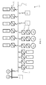
- FIG. 3 shows typical demand circuits 30 with their power switching units 32, 33, 34.
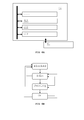
- Figure 4A represents a scheme of a centralized controller.
- Figure 4B represents a four-state controller for the power switch units
- Figure 5 shows LED flashing codes.
- the invention relates to power load management systems, which refer to methods and/or devices for balancing the demand of electrical power to the availability thereof.
- power load management systems are useful in grids where the electrical power available is at least temporarily limited.
- the different loads connected to the grid which can be electrical power consuming circuits of various kind, are connected through power switches.
- a power switch enables to disconnect the load connected to that switch from the electrical grid in order to limit the demand for electrical power within the system.
- the operation of the power switches is supervised by a controller, which is preferably centralized.
- the central (or centralized) controller decides when and if a power switch is closed or opened.
- Each power switch can be provided as a module additionally comprising a unit which is configured to manage the operation (actuation) of the power switch, the communication with the (central) controller, and which is possibly also configured to measure the electrical power consumed by the circuit (the load).
- a power switch can only be closed after a request has been sent for closing the power switch. This can be the case for some, or for all the power switches.
- a request can be sent to the central controller by a user or a client process related to the circuit (the load).
- the request is processed and analysed by the controller, which verifies that closure of the power switch will not cause the demand of electrical power to exceed the available power.
- the verification can be performed based on measuring the total demand within the system (e.g. at a single location in the system) and/or separately measuring the demand of some (or all) the circuits. The two measurements can be combined.
- the verification of the request by the controller can take into account an expected demand of the corresponding circuit. This can be a rated demand, or an extrapolation based on historical data concerning the circuit.
- the verification of the request can comprise comparing the expected increase in the demand (i.e. the expected demand of the corresponding circuit) with the available reserve of electrical power and/or energy.
- a correction factor can be applied (i.e. the actual reserve is multiplied by a number ⁇ 1), such that a smaller power reserve is used in the comparison.
- Measurements of electrical power demand, as well as of the available electrical power can be predetermined, either in advance, or preferably real-time.
- the central controller is aware of every process (circuit) that is about to take up power, and is able to check the impact of the potential electrical power consumption of the circuit before releasing its operation.
- a power switch can be opened after the circuit has terminated with drawing power, after a time slot that has been accorded to the circuit/the power switch has elapsed, after the time for the circuit to actually draw power after it was connected has elapsed without effect, or according to other policies.
- the available power resources can be used efficiently and be distributed to circuits which actually require power at the given instant of time.
- the controller can avoid to take into account potential power demand of "sleeping" circuits (i.e. circuits which at a given instant do not consume power).
- a preferred embodiment concerns the implementation of one of the policies of opening a power switch.
- a circuit once a circuit has been connected to the grid, it has a predetermined time delay for actually starting to draw power from the grid. If it does not (the central controller e.g. monitors a power below a predetermined threshold), the corresponding power switch is opened and can remain blocked for a predetermined time period.
- the circuit/the power switch after closing of the power switch associated with a circuit, receives a time slot in which the power switch remains closed. Upon expiry of the time slot, the power switch is forced to open.
- priority ranking rules can be implemented in the central controller, for assigning a priority level to each of the circuits (and hence each of the corresponding power switches).
- Systems according to the invention can be implemented in an operational base or station.
- the electricity demand can be much influenced by the momentary activities of the crews. It is possible, often without any compromise with the working and living comfort to restrict the supply to specific areas.
- Systems of the invention can do this by considering different operation modes that match the current activities in the base:
- the switching from one mode to another can be triggered by user requests (such as by push buttons or touch screens), client processes, timers & clocks, electrical parameters and alarms.
- Operation modes can be implemented in combination with priority ranking. Each time the operation mode is modified, the priority levels of the (demand) circuits or loads are revised and updated.
- Specific conditions can be defined for each transition. For example, a user cannot cause a transition into the kitchen mode when the Fire & evacuation mode is on.
- the control of the power switch of a controlled distribution circuit is preferably based on a four-state controller as illustrated in figure 4B .
- the power switch In the “Idle” state, the power switch is open and no requests for closing the switch are pending. In the “Pending” state, the power switch is open and a request for closing the switch is pending. In the “On” state, the power switch is closed.
- the Pending - Idle time-out refers to the time after which the "Pending" state returns to "Idle".
- the self-release time refers to the delay to return to "Idle” state if the demand remained below the detection threshold.
- the detection threshold can be expressed in % of the rated demand.
- the lock-on time refers to the time during which the "On” state is secured.
- the lock-out time refers to the time after which transition from "On" to “Blocked” is forced.
- the blocking time refers to the duration of stay in "Blocked” state (zero if the timer is not activated).
- the above parameters can be defined in a configuration menu for each circuit's priority level and per operation mode as illustrated in table 1. They can be defined user by user or per process or group (HVAC, kitchen,...) .
- Table 1 Typical parameters for the control of the circuits connected to the grid via a (controllable) power switch.
- the power switches are advantageously arranged to be remote controlled.
- An interface can be provided for communicating between the central controller and a power switch, preferably enabling bidirectional (or two-way) communication. This can allow the user or client process to be informed about the current state of the power switch.
- the interface can comprise a user interface for requesting energizing of a circuit by engagement of a power switch, such as a local unit with a push-button for sending pulses to the controller and a LED (light emitting diode) actuated by the controller.
- a power switch such as a local unit with a push-button for sending pulses to the controller and a LED (light emitting diode) actuated by the controller.
- the user interface can be an interface for a client process.
- the pulses sent by the user can trigger the ["Idle” to “Pending”], ["Pending” to “Idle] and ["ON" to “Idle”] transitions of the power switch (circuit) to which they are associated.
- a dead time interval is preferred before repeating a pulse, such as a dead time interval of 3 s.
- the LED of the user interface can be used for informing the user about the course of his request:
- the user can request or force change of modes trough various types of interfaces such as touch screens, emergency buttons and particularly also through the same simple interface as described here above.
- the control logic can be the same and, by so doing, the LED flashing codes can be used for informing the user about the course of his request.
- the central controller advantageously comprises a priority manager.
- the priority manager is preferably permanently cycling, for making an arbitration between the requests and priorities and possibly for calculating the power reserve.
- the true limitation of the power source is on the current rather than on the power.
- the calculation (of power or current) is preferably done phase by phase since the demand is not necessarily equally balanced between the three phases.
- the central controller can make an arbitration between the power (or current) reserve (availability) and the requests by the various circuits (loads).
- a correction factor can be applied to the power (current) reserve.
- a correction factor refers to a multiplication of the actual power (current) reserve by a number ⁇ 1.
- a correction factor e.g. of 0.5
- the actual available energy reserve e.g. state of charge of the batteries
- the actual energy reserve e.g. state of charge of the batteries
- the priority manager can make an arbitration between power demand and current circuit priorities, possibly disconnecting circuits of lower priority for accepting power demands of higher priorities.
- the priority manager can trigger transitions from 'ON' to 'Pending' or 'Idle' in such a way that the prospective increase of demand remains under the limits of the reserve power of each phase, with due consideration for the parameters and state registers of the circuit controller units.
- the central controller can make use of the actual current (or taken up power) for deciding on which power switch possibly to open.
- the central controller can make use of the rated demand of the circuit for deciding which request for closing to grant.
- the priority manager can make an arbitration between circuits on same data.
- the rated demand is preferably taken into account in cases wherein no measurement is available.
- the periodicity of the working cycle of the central controller is preferably such that the power switches have the time to establish or to clear the circuits (maximum reaction time of contactors etc.) between two cycles.
- the power system 10 as illustrated in figure 1 is designed for an operational base without any external power supply or public grid; it is designed to use renewable energy sources for electricity generation.
- the power supply consists of:
- the total potential demand consisting of loads 16, 6 kW dump loads 17 and loads 18 related to garage and welding tools, amounts to 400 kVA, significantly more than the installed generation capacity.
- Voltage regulation and power balancing are achieved by AC/DC battery inverters 14 from SunnyIslandTM. They are synchronized and take care of a primary regulation by implementing droops for active power/frequency and reactive power/voltage control (see figure 2a ).
- the renewable sources work at maximum available power but, if the system frequency (controlled by the inverters) exceeds 51 Hz, their production is curtailed ( figure 2b ).
- the blade angle of the wind turbines is not adjustable and the excess energy produced by the wind generator is dissipated in resistors (this energy can be recuperated for water de-icing and heating), whereas the maximum power point operating mode (MPP) of the PV modules is modified accordingly.
- MPP maximum power point operating mode
- the inverter is permanently tracking on the U-I characteristic of the PV cells the point maximising the power output; it varies in function of the momentary actual solar radiation, cell temperature, age, surface pollution.
- the operating mode of the PV modules is changed from MPP to a regulation mode where the power output is limited according to the system power frequency deviation.
- the purpose is to keep the frequency within limits even when the source power exceeds the demand (of course when yet there is no more possibility of energy storage in the batteries).
- the power curtailment is frequency driven, in such a way that it is adequately shared between the sources.
- the inverter characteristic is such that when the renewable sources are curtailed, any possibility to increase the rate of charge of the batteries has been used already.
- the genset is started by the battery inverter. In this case, the battery inverters switch to constant charge operation while the power balancing is taken over by the genset.
- This system is stable in voltage and frequency as far as it works within the regulating limits of the inverters. In such applications, covering the demand in all possible situations would lead to over dimensioned inverters. This is avoided by systems (methods and/or devices) according to the present invention.
- the demand power management system is focusing on instantaneous power limitation in order to keep the system in safe working conditions.
- the distribution circuits can be of the following type (see figure 3 ):
- a power switch module comprises the power switch and associated control unit.
- the control unit can be arranged for actuating the power switch upon reception of a signal.
- the control unit can further comprise a communication unit and/or a measurement unit.
- the total demand as well as the demand seen by the main power switch modules (main control units 32 and 33) is measured and transmitted to the central controller.
- the total demand of electrical power can be measured at a measurement unit 35 on the (main) grid 19.
- the demand of different circuits can be measured locally by measurement units 321 and 331 for example. Each circuit is represented in figure 3 with an electrical power consuming load 30.
- Each measurement unit measures the amplitude of the current of the three individual phases.
- the currents fed-in by the inverters (positive or negative) and genset are also measured.
- the centralized controller 40 stands for all the processes (see figure 4A ).
- the demand power management module 401 which is part of it, communicates with remote controlled units 41, such as switching units (the power switches / control units), user interfaces for power or priority requests, measurement units for the power demand, alarms and emergency signals and other units.
- the centralized controller 40 can comprise additional modules for managing other units, such as
- Two-way communication between the demand management module and other modules can include power demand requests, priority requests, demand measurements, alarms, switching controller status,...
- the control of the power switch of a controlled distribution circuit is based on a four-state controller as identified above.
- the user interface for requesting energizing of a circuit is a local unit with a push-button for sending pulses to the controller and a LED (light emitting diode) actuated by the controller.
- the pulses sent by the user trigger the ["Idle” to “Pending”], ["Pending” to “Idle] and ["ON" to “Idle”] transitions of the circuit to which they are associated.
- the priority manager is permanently cycling, for calculating the power reserve and for making an arbitration between the requests and priorities.
- the calculation of the power reserve is made in terms of current instead of active power. Moreover, the calculation is done phase by phase since the demand is not necessarily equally balanced between the three phases.
- the priority manager makes an arbitration between power demand and current circuit priorities, possibly disconnecting circuits of lower priority for accepting power demands of higher priorities.
- the priority manager triggers transitions from 'ON' to 'Pending' or 'Idle' in such a way that the prospective increase of demand remains under the limits of the reserve power of each phase, with due consideration for the parameters and state registers of the circuit controller units.
- the demand management module can also switch off the circuits for which a phase current would exceed a predefined level.
Landscapes
- Engineering & Computer Science (AREA)
- Power Engineering (AREA)
- Supply And Distribution Of Alternating Current (AREA)
Abstract
Description
- The present invention is related to electrical power load management within an entity fed by a power limited supply system where the potential demand largely exceeds the power limits.
- In small power systems that are permanently or temporarily operated without a connection to a powerful electricity distribution system, a demand management system, be it quite current like frequency driven load shedding, is necessary for balancing demand and supply. In such power systems, the stability and security criteria requires avoiding exceeding the power supply limits, even for very short periods. On the other hand, advanced prioritization methods have to be used for fulfilling the demand in a flexible and user-friendly way.
- Current demand management methods typically focus on time interval balancing, focussing on economic optimisation without consideration for instantaneous exceeding of the stability limits.
- Patent application
WO 2004/023624 discloses a power load management system, wherein load control switches provide feedback data to a load management CPU. The load management CPU monitors the load feedback data and other operational parameters for selectively switching load control switches to the open circuit state in order to ensure that the total load demanded does not exceed the demand limits imposed by the power source. The load management CPU allows automatic prioritization of the loads. - Whereas such a system guarantees that the power limits are never exceeded, it fails to use the available power efficiently and flexibly. In order to be able to supply all high priority loads with power, an unnecessary margin has to be foreseen on the power demand, leading to an increased cost, or reduced operation.
- It is an aim of the invention to provide a power load management method and device which overcomes drawbacks of methods and devices of the prior art. In particular, it is an aim of the invention, to provide a power load management method and device, which enables to use the available electrical power more efficiently and/or with greater flexibility.
- The invention relates to power load management systems, which refer to methods and/or devices for balancing the demand of electrical power to the availability thereof. Power load management methods and devices according to the invention can preserve the need for safe operation while responding to user's and client's process requirements. In order to avoid unexpected overrides of the limits, methods and devices of the invention handle power demand requests and analyze them before releasing the demand.
- According to a first aspect of the invention, there is provided a method of balancing the demand of electrical power to the availability thereof in a system comprising a plurality of electrical power consuming circuits, the system supplied at least temporarily with limited electrical power by a supply, wherein the method comprises the steps of: connecting each of said circuits to the supply through a power switch, providing a controller for controlling operation of the power switches, closing the power switch of a circuit and opening the closed power switch. According to the invention, the step of closing the power switch comprises the steps of: firstly, sending a request to the controller for closing the power switch, secondly analysing the request by the controller in order to verify that the total demand of electrical power of the system will not exceed a predetermined limit upon closing the power switch and thirdly closing the power switch if verification resulted in that said total demand of electrical power will not exceed the predetermined limit upon closing said power switch.
- Preferably, the predetermined limit is calculated based on the available electrical power in the system, or by the supply. Alternatively, the predetermined limit is calculated based on the electrical power reserve in the system, or by the supply. More preferably, for instance when storage batteries are used or when a generator set with limited fuel reserve is used, the predetermined limit is calculated also based on the energy reserve available in the system (in the supply).
- Preferably, the method comprises the step of forcing the closed power switch to open after a predetermined time period.
- Preferably, the method comprises the step of forcing the closed power switch to open if the power drawn by the circuit remained below a predetermined threshold over a predetermined second time period.
- Preferably, the power switch is (state) controlled based on: an idle state wherein the power switch is open and idle, a closed state wherein the power switch is closed and a pending state wherein the power switch is open and a request for closing the switch is pending. Each transition from the open state to the closed state passes through the pending state. More preferably, the power switch is (state) controlled based on an additional blocked state wherein the power switch is open and the operation of the power switch is blocked. At least one possible transition from the closed state to the open state passes through the blocked state. The power switch is hence preferably controlled based on multiple states, possibly at least three states and more preferably four states, or more.
- Preferably, the method comprises the step of scheduling a priority ranking for the circuits. The power switch of a first circuit can be opened following a second circuit of higher priority than the first circuit sending a request for closing and if the predetermined limit would be exceeded upon closing the second circuit.
- Preferably, the method comprises the step of sending a signal by the controller in order to acknowledge a reception of the request for closing. More preferably, the method comprises the step of cancelling the request for closing, the cancelling step comprising sending a second request for closing to the controller following the step of sending a signal. The step of sending a second request cancels the request for closing. Pumping can be avoided by disabling the controller input for receiving the requests during a predetermined time period (dead time).
- Preferably, the (total) demand of electrical power of the system is the (total) instantaneous demand. Alternatively, the (total) demand of electrical power of the system is the interval averaged demand.
- Preferably, the demand of electrical power of the system is measured and evaluated in current amplitudes.
- In a preferred embodiment, the invention implements a method or device with different operation modes that ensure flexibility and interactivity with the user's and client's processes. In particular, it implements a simple interface for entering power demand and/or priority requests.
- The invention is applicable to any system where demands are managed by a central controller with preferably real time communication for measurement and control of the electric circuits.
- According to an aspect, the present invention relates to an electricity demand management method that is implemented in a centralized controller and that schedules the activation, curtailment or shedding of several electrical circuits in order to limit the total instantaneous or time averaged power demanded by a group of circuits.
- Any of the above methods of the invention can use real time measurements of the total demand, possibly by summation of individual demand signals. In addition, or alternatively, they can use real time measurements of the current in the individual circuits under control; possibly for part of them if the measurement of the total demand is independently available.
- In addition, or alternatively, any of the above methods of the invention can use data characterizing each demand circuit, specifically concerning the rated or expected demand of the circuit (the load).
- In addition, or alternatively, any of the above methods of the invention can use data characterizing the power supply conditions and constraints. In addition, or alternatively, they can use real time information about the power supply capability.
- Methods according to the invention can use direct control of a contactor switch on each circuit under control.
- Methods according to the invention can use a priority ranking system between the different circuits.
- For some or all of the circuits/power switches, when a circuit/power switch is in the open state, it closes only after a request has been issued by the user or by a client process, and analyzed by the controller which is verifying that, after closing, the total instantaneous (power) or interval averaged demand will not exceed the prescribed limits.
- Preferably, the limit is fixed by the reserve power available on the system.
- Preferably, the demand is measured and evaluated in current amplitudes (Amps).
- Preferably, the same controller contributes to the protection selectivity when the system operates in low short-circuit power conditions.
- Preferably, any of the above methods according to the invention uses multiple exclusive modes of operation having each their own priority ranking systems and algorithms, the switching between said modes being triggered by:
- local user requests for change of mode and, or, local user power demand requests, and/or
- programmed time schedules or constraints, and/or
- alarm and emergency signals, and/or
- signals from appliances or client processes.
- Change of mode requests can also be entered and supervised by the local or remote consoles of the central controller.
- Preferably, local user requests are given through 2-way communicating interfaces equipped with a push button for sending pulses to the controller and with a light emitting device controlled by the central controller.
- Preferably, after reception of a request, the light emitting device is activated following specific flashing codes, informing the user about reception of his request and the priority received. When this is established, a further activation of the push button cancels the request.
- According to another aspect of the invention, there is provided a device for balancing the demand of electrical power to the availability thereof. The device is connectable in a system which comprises a plurality of electrical circuits arranged to consume electrical power, the system in use being supplied at least temporarily with limited electrical power by a supply that additionally is possibly limited in energy. The device according to the invention comprises: a plurality of power switches for connecting the electrical circuits to the supply and a controller for controlling the operation of the power switches. The device further comprises means for carrying out the method according to any one of the preceding claims.
- Preferably, the controller is (at least) a three-state controller, more preferably a four-state controller for at least one power switch.
- Preferably, the device comprises an interface for two-way communication between the power switches and the controller. More preferably, the interface for two-way communication comprises a push button for sending pulses to the controller and a light emitting device controlled by the controller. Even more preferably, the light emitting device is configured to emit light according to predetermined flashing codes relating to the analysis by the controller of a request for closing and/or to a priority ranking.
-
Figure 1 shows the power system on which the invention is applied. -
Figure 2a shows the frequency droop characteristic of the inverters. -
Figure 2b represents the frequency driven curtailment of the renewable sources. -
Figure 3 showstypical demand circuits 30 with theirpower switching units -
Figure 4A represents a scheme of a centralized controller.Figure 4B represents a four-state controller for the power switch units -
Figure 5 shows LED flashing codes. - The invention relates to power load management systems, which refer to methods and/or devices for balancing the demand of electrical power to the availability thereof. Such power load management systems are useful in grids where the electrical power available is at least temporarily limited.
- The different loads connected to the grid, which can be electrical power consuming circuits of various kind, are connected through power switches. A power switch enables to disconnect the load connected to that switch from the electrical grid in order to limit the demand for electrical power within the system.
- According to the invention, the operation of the power switches is supervised by a controller, which is preferably centralized. The central (or centralized) controller decides when and if a power switch is closed or opened.
- Each power switch can be provided as a module additionally comprising a unit which is configured to manage the operation (actuation) of the power switch, the communication with the (central) controller, and which is possibly also configured to measure the electrical power consumed by the circuit (the load).
- According to the invention, a power switch can only be closed after a request has been sent for closing the power switch. This can be the case for some, or for all the power switches. Such a request can be sent to the central controller by a user or a client process related to the circuit (the load).
- The request is processed and analysed by the controller, which verifies that closure of the power switch will not cause the demand of electrical power to exceed the available power. The verification can be performed based on measuring the total demand within the system (e.g. at a single location in the system) and/or separately measuring the demand of some (or all) the circuits. The two measurements can be combined. In addition, the verification of the request by the controller can take into account an expected demand of the corresponding circuit. This can be a rated demand, or an extrapolation based on historical data concerning the circuit.
- The verification of the request can comprise comparing the expected increase in the demand (i.e. the expected demand of the corresponding circuit) with the available reserve of electrical power and/or energy. In case the available reserve is slim, e.g. below a predetermined threshold, a correction factor can be applied (i.e. the actual reserve is multiplied by a number < 1), such that a smaller power reserve is used in the comparison.
- Only after a positive verification that the expected total demand will not exceed a predetermined limit representative of the available power (or similarly that the expected increase in demand does not exceed a predetermined limit representative of the available reserve) will the request for closing the power switch be granted.
- Measurements of electrical power demand, as well as of the available electrical power can be predetermined, either in advance, or preferably real-time.
- By so doing, the central controller is aware of every process (circuit) that is about to take up power, and is able to check the impact of the potential electrical power consumption of the circuit before releasing its operation.
- A circuit (or a load) which has been connected to the grid, and thus to the electrical power supply, by closing the power switch, is disconnected afterwards. A power switch can be opened after the circuit has terminated with drawing power, after a time slot that has been accorded to the circuit/the power switch has elapsed, after the time for the circuit to actually draw power after it was connected has elapsed without effect, or according to other policies. By so doing, the available power resources can be used efficiently and be distributed to circuits which actually require power at the given instant of time. Also, the controller can avoid to take into account potential power demand of "sleeping" circuits (i.e. circuits which at a given instant do not consume power).
- A preferred embodiment concerns the implementation of one of the policies of opening a power switch. Once a circuit has been connected to the grid, the central controller will monitor the power it draws. If the power drawn by the circuit falls below a predetermined threshold (e.g. can not be detected) for a predetermined time period, the central controller will disconnect the circuit by opening the corresponding power switch. If the circuit wants to draw power again, a new request has to be sent to the central controller.
- According to another preferred embodiment, once a circuit has been connected to the grid, it has a predetermined time delay for actually starting to draw power from the grid. If it does not (the central controller e.g. monitors a power below a predetermined threshold), the corresponding power switch is opened and can remain blocked for a predetermined time period.
- According to another embodiment, after closing of the power switch associated with a circuit, the circuit/the power switch receives a time slot in which the power switch remains closed. Upon expiry of the time slot, the power switch is forced to open.
- Two or more of the policies identified in the above embodiments can be implemented in combination in a single method according to the invention.
- In addition, priority ranking rules can be implemented in the central controller, for assigning a priority level to each of the circuits (and hence each of the corresponding power switches).
- Systems according to the invention can be implemented in an operational base or station. In such an operational base, the electricity demand can be much influenced by the momentary activities of the crews. It is possible, often without any compromise with the working and living comfort to restrict the supply to specific areas. Systems of the invention can do this by considering different operation modes that match the current activities in the base:
- Start-up
- Normal mode
- Office & laboratory mode
- Kitchen mode
- Medical aid mode
- Living room mode
- Derated power mode
- Genset mode
- Fire & evacuation mode
- Survival mode
- Winter mode
- Shutdown
- The switching from one mode to another can be triggered by user requests (such as by push buttons or touch screens), client processes, timers & clocks, electrical parameters and alarms.
- Operation modes can be implemented in combination with priority ranking. Each time the operation mode is modified, the priority levels of the (demand) circuits or loads are revised and updated.
- Specific conditions can be defined for each transition. For example, a user cannot cause a transition into the kitchen mode when the Fire & evacuation mode is on.
- The control of the power switch of a controlled distribution circuit is preferably based on a four-state controller as illustrated in
figure 4B . - The key issue is that a power switch always passes through a "Pending" state before going to the "On" state; any demand is analysed before being released. The power switch is engaged in the "On" state only.
- In the "Idle" state, the power switch is open and no requests for closing the switch are pending. In the "Pending" state, the power switch is open and a request for closing the switch is pending. In the "On" state, the power switch is closed.
- In a possibly additional "Blocked" state, the power switch is open and its operation is blocked. In this case, the requesting user or process can be immediately informed that his requests will be ignored (see further interface). The "Blocked" state provides the advantage of safer programming the controller.
- In the following, possible state transition conditions are identified:
- from "Idle" to "Pending"
- o local user request (user interface - activation of the push-button)
- o internal request from the controller (time scheduler, change of operation mode, emergency management, requests from client processes, ..)
- from "Idle" to "Blocked"
- o for specific changes of operation mode (including emergency management, shutdown,..)
- from "Pending" to "On"
- o reserve power is higher than expected incremental demand, under control of the priority manager
- from "Pending" to "Idle"
- o local user request cancelling the demand (user interface - activation of the push-button)
- o Pending-Idle time-out as defined for the current priority allocated to the circuit
- from "Pending" to "Blocked"
- o for specific change of operation mode (including emergency management, shutdown, ...)
- from "ON" to "Idle"
- o local user request releasing the demand (user interface - activation of the push-button )
- o decision of the priority manager, but not before a secured time interval defined by the lock-on time parameter defined for the current priority allocated to the circuit
- o demand remained below the detection threshold during a period longer that the self-release time
- from "ON" to "Pending"
- o for specific change of operation mode (including emergency management, shutdown, ...)
- from "ON" to "Blocked"
- o Lock-out time as defined for the corresponding circuit within the current operating mode; sets a Blocking time controlling the time in the "Blocked" state
- from "Blocked" to "Idle"
- o Blocking time (if activated)
- o internal request from the controller (time scheduler, change of operation mode, emergency management, request through controller console)
- The Pending - Idle time-out refers to the time after which the "Pending" state returns to "Idle".
- The self-release time refers to the delay to return to "Idle" state if the demand remained below the detection threshold.
The detection threshold can be expressed in % of the rated demand.
The lock-on time refers to the time during which the "On" state is secured.
The lock-out time refers to the time after which transition from "On" to "Blocked" is forced.
The blocking time refers to the duration of stay in "Blocked" state (zero if the timer is not activated). - The above parameters can be defined in a configuration menu for each circuit's priority level and per operation mode as illustrated in table 1. They can be defined user by user or per process or group (HVAC, kitchen,...) .
Table 1: Typical parameters for the control of the circuits connected to the grid via a (controllable) power switch. Priority level Pending-Idle Timeout (min) Self release time (min) Detection threshold (%) Lock-on time (min) Lock-out time (s) Blocking time (min) 1 ∞ ∞ 0 ∞ ∞ 0 2 30 30 By user 30 60 5 3 15 15 By user 15 45 15 4 5 5 By user 5 30 30 5 1/10 1 By user 0 15 60 - The power switches are advantageously arranged to be remote controlled. An interface can be provided for communicating between the central controller and a power switch, preferably enabling bidirectional (or two-way) communication. This can allow the user or client process to be informed about the current state of the power switch.
- The interface can comprise a user interface for requesting energizing of a circuit by engagement of a power switch, such as a local unit with a push-button for sending pulses to the controller and a LED (light emitting diode) actuated by the controller. Alternatively, the user interface can be an interface for a client process.
- The pulses sent by the user (or the client) can trigger the ["Idle" to "Pending"], ["Pending" to "Idle] and ["ON" to "Idle"] transitions of the power switch (circuit) to which they are associated.
- For avoiding pumping, a dead time interval is preferred before repeating a pulse, such as a dead time interval of 3 s.
- The LED of the user interface can be used for informing the user about the course of his request:
- the LED is OFF when the controller is in the "Blocked" state;
- the LED is ON:
- when the push-button is depressed, except in the "Blocked" state; for the user, this is a confirmation that the controller is sensing his input, or
- when the controller is in the "ON" state, while the demand is above the detection threshold level;
- the LED is flashing such as in cases as represented in
figure 5 . - The user can request or force change of modes trough various types of interfaces such as touch screens, emergency buttons and particularly also through the same simple interface as described here above. In the latter case, the control logic can be the same and, by so doing, the LED flashing codes can be used for informing the user about the course of his request.
- In case of a priority ranking of the various circuits, the central controller advantageously comprises a priority manager. The priority manager is preferably permanently cycling, for making an arbitration between the requests and priorities and possibly for calculating the power reserve.
- In some cases, the true limitation of the power source is on the current rather than on the power. In those cases, it can be advantageous to make the calculation of the power reserve in terms of current instead of active power. Moreover, the calculation (of power or current) is preferably done phase by phase since the demand is not necessarily equally balanced between the three phases.
- Once the power reserve (in Amps) has been calculated, possibly for each phase, the central controller can make an arbitration between the power (or current) reserve (availability) and the requests by the various circuits (loads).
- In case the power (current) reserve is below a predetermined threshold, and/or in case the total available energy reserve (state of charge of batteries, fuel reserve, ...) is below a predetermined threshold, a correction factor can be applied to the power (current) reserve. A correction factor refers to a multiplication of the actual power (current) reserve by a number < 1. For example, a correction factor (e.g. of 0.5) can be applied to the power (current) reserve, or to the total available power (current) in case the actual available energy reserve (e.g. state of charge of the batteries) is smaller than between 35% and 15% of a nominal value, e.g. smaller than 25%.
In case the actual energy reserve (e.g. state of charge of the batteries) is smaller than between 20% and 5% of a nominal value, e.g. smaller than 15%, absolute priority is preferably given to the reconstitution of the energy reserve (e.g. state of charge of the batteries), possibly considering a total lack of power reserve (setting power reserve to zero). - In case of a priority manager, the priority manager can make an arbitration between power demand and current circuit priorities, possibly disconnecting circuits of lower priority for accepting power demands of higher priorities.
- The priority manager can trigger transitions from 'ON' to 'Pending' or 'Idle' in such a way that the prospective increase of demand remains under the limits of the reserve power of each phase, with due consideration for the parameters and state registers of the circuit controller units.
- For circuits (or loads) that are 'on' and hence consuming power, the central controller can make use of the actual current (or taken up power) for deciding on which power switch possibly to open. The central controller can make use of the rated demand of the circuit for deciding which request for closing to grant. The priority manager can make an arbitration between circuits on same data. The rated demand is preferably taken into account in cases wherein no measurement is available.
- The periodicity of the working cycle of the central controller (and possibly of the priority manager) is preferably such that the power switches have the time to establish or to clear the circuits (maximum reaction time of contactors etc.) between two cycles.
- The invention will be understood better from the following description of an embodiment thereof provided by way of example and therefore in no way limiting, and given with reference to the appended drawings.
- The
power system 10 as illustrated infigure 1 is designed for an operational base without any external power supply or public grid; it is designed to use renewable energy sources for electricity generation. - For security reasons, the system is equipped with a kerosene fuelled emergency generator set. The power supply consists of:
- 9 x 6 kW
peak wind turbines 11, coupled to thegrid 19 by AC/DC inverters 111 and DC/AC inverters 112; - 63 kW peak Photovoltaic (PV)
modules 12, coupled to thegrid 19 by DC/AC inverters 121; - 4 x 2000 Ah
x 48V batteries 13; - 4 sets of 3 x 5 kW single phase synchronized AC/
DC inverters 14 for driving thebatteries 13 and stabilizing thesystem 10 and - 2 x 40 kVA
emergency genset 15. - The total potential demand, consisting of
loads 16, 6 kW dump loads 17 and loads 18 related to garage and welding tools, amounts to 400 kVA, significantly more than the installed generation capacity. - Voltage regulation and power balancing are achieved by AC/
DC battery inverters 14 from SunnyIsland™. They are synchronized and take care of a primary regulation by implementing droops for active power/frequency and reactive power/voltage control (seefigure 2a ). - The renewable sources work at maximum available power but, if the system frequency (controlled by the inverters) exceeds 51 Hz, their production is curtailed (
figure 2b ). The blade angle of the wind turbines is not adjustable and the excess energy produced by the wind generator is dissipated in resistors (this energy can be recuperated for water de-icing and heating), whereas the maximum power point operating mode (MPP) of the PV modules is modified accordingly. In the MPP mode, the inverter is permanently tracking on the U-I characteristic of the PV cells the point maximising the power output; it varies in function of the momentary actual solar radiation, cell temperature, age, surface pollution. In the present installation, when the system frequency exceeds a predetermined limit, such as 51 Hz (for a 50 Hz grid, seefigure 2b ), the operating mode of the PV modules is changed from MPP to a regulation mode where the power output is limited according to the system power frequency deviation. The purpose is to keep the frequency within limits even when the source power exceeds the demand (of course when yet there is no more possibility of energy storage in the batteries). The power curtailment is frequency driven, in such a way that it is adequately shared between the sources. - So doing, the inverter characteristic is such that when the renewable sources are curtailed, any possibility to increase the rate of charge of the batteries has been used already.
- If only 20% of battery energy is left, the genset is started by the battery inverter. In this case, the battery inverters switch to constant charge operation while the power balancing is taken over by the genset.
- This system is stable in voltage and frequency as far as it works within the regulating limits of the inverters. In such applications, covering the demand in all possible situations would lead to over dimensioned inverters. This is avoided by systems (methods and/or devices) according to the present invention. The demand power management system is focusing on instantaneous power limitation in order to keep the system in safe working conditions.
- The distribution circuits can be of the following type (see
figure 3 ): - Always on circuits 31 (i.e. constantly closed power switch, or no power switch at all)
- Individually controlled circuit with a
power switch module 32. - Multi load circuits with main control (main power switch modules 33) and sub control units (sub power switch modules 34).
- A power switch module comprises the power switch and associated control unit. The control unit can be arranged for actuating the power switch upon reception of a signal. The control unit can further comprise a communication unit and/or a measurement unit.
- The total demand as well as the demand seen by the main power switch modules (
main control units 32 and 33) is measured and transmitted to the central controller. The total demand of electrical power can be measured at ameasurement unit 35 on the (main)grid 19. The demand of different circuits can be measured locally bymeasurement units 321 and 331 for example. Each circuit is represented infigure 3 with an electricalpower consuming load 30. - Each measurement unit measures the amplitude of the current of the three individual phases. The currents fed-in by the inverters (positive or negative) and genset are also measured.
- The
centralized controller 40 stands for all the processes (seefigure 4A ). The demandpower management module 401 which is part of it, communicates with remote controlledunits 41, such as switching units (the power switches / control units), user interfaces for power or priority requests, measurement units for the power demand, alarms and emergency signals and other units. Thecentralized controller 40 can comprise additional modules for managing other units, such as -
Water treatment module 402 -
HVAC management module 403 - Fire security module
- ....
- Two-way communication between the demand management module and other modules can include power demand requests, priority requests, demand measurements, alarms, switching controller status,...
- The control of the power switch of a controlled distribution circuit is based on a four-state controller as identified above.
- The user interface for requesting energizing of a circuit is a local unit with a push-button for sending pulses to the controller and a LED (light emitting diode) actuated by the controller.
- The pulses sent by the user trigger the ["Idle" to "Pending"], ["Pending" to "Idle] and ["ON" to "Idle"] transitions of the circuit to which they are associated.
- For avoiding pumping, a dead time interval of 3s is necessary before repeating a pulse.
- The priority manager is permanently cycling, for calculating the power reserve and for making an arbitration between the requests and priorities.
- The true limitation of the power inverters being on the current rather than on the power, the calculation of the power reserve is made in terms of current instead of active power. Moreover, the calculation is done phase by phase since the demand is not necessarily equally balanced between the three phases.
-


- Once the power reserve (in Amps) has been calculated for each phase, the priority manager makes an arbitration between power demand and current circuit priorities, possibly disconnecting circuits of lower priority for accepting power demands of higher priorities.
- The priority manager triggers transitions from 'ON' to 'Pending' or 'Idle' in such a way that the prospective increase of demand remains under the limits of the reserve power of each phase, with due consideration for the parameters and state registers of the circuit controller units.
- When the system is operated in "power derated mode" the demand management module can also switch off the circuits for which a phase current would exceed a predefined level.
Claims (15)
- A method of balancing the demand of electrical power to the availability thereof in a system (10), the system comprising a plurality of electrical power consuming circuits (16,17,18,30) and supplied at least temporarily with limited electrical power by a supply (11,12,13,15), wherein the method comprises the steps of:- connecting each of said circuits to the supply through a power switch (32,33,34),- providing a controller for controlling operation of the power switches,- closing the power switch of a circuit and- opening the closed power switch,wherein the step of closing the power switch comprises the steps of:- sending a request to the controller for closing the power switch,- analysing the request by the controller in order to verify that the total demand of electrical power of the system will not exceed a predetermined limit upon closing the power switch,- closing the power switch if verification resulted in that said total demand of electrical power will not exceed the predetermined limit upon closing said power switch.
- The method according to claim 1, comprising the step of forcing the closed power switch to open after a predetermined time period.
- The method according to claim 1 or 2, comprising the step of forcing the closed power switch to open if the power drawn by the circuit remained below a predetermined threshold over a predetermined second time period.
- The method according to any one of the preceding claims, wherein the power switch is controlled based on:- an idle state wherein the power switch is open and idle,- a closed state wherein the power switch is closed and- a pending state wherein the power switch is open and a request for closing the switch is pending,and wherein each transition from the open state to the closed state passes through the pending state.
- The method according to claim 4, wherein the power switch is controlled based on an additional blocked state wherein the power switch is open and the operation of the power switch is blocked and wherein a transition from the closed state to the open state passes through the blocked state.
- The method according to any one of the preceding claims, the supply at least temporarily comprising limited energy, wherein both the reserve of electrical power available from the supply and the reserve of energy available in the supply are taken into account for calculating the predetermined limit.
- The method according to any one of the preceding claims, comprising the step of sending a signal by the controller in order to acknowledge a reception of the request for closing.
- The method according to claim 7, comprising the step of cancelling the request for closing, the cancelling step comprising sending a second request for closing to the controller following the step of sending a signal, the step of sending a second request cancelling the request for closing.
- The method according to any one of the preceding claims, wherein the total demand of electrical power of the system is the total instantaneous demand or the total interval averaged demand.
- The method according to any one of the preceding claims, wherein the demand of electrical power of the system is measured and evaluated in current amplitudes.
- A device for balancing the demand of electrical power to the availability thereof, connectable in a system, the system comprising a plurality of electrical circuits arranged to consume electrical power, the system in use being supplied at least temporarily with limited electrical power by a supply, wherein the device comprises:- a plurality of power switches (32,33,34) for connecting the electrical circuits to the supply and- a controller for controlling the operation of the power switches,wherein the device comprises means for carrying out the method according to any one of the preceding claims.
- The device according to claim 11, wherein the controller is a state controller for at least one power switch, the state controller implementing at least three states, preferably four states.
- The device according to claim 11 or 12, comprising an interface for two-way communication between the power switches and the controller.
- The device according to claim 13, wherein the interface for two-way communication comprises a push button for sending pulses to the controller and a light emitting device controlled by the controller.
- The device according to claim 14, wherein the light emitting device is configured to emit light according to predetermined flashing codes relating to the analysis by the controller of a request for closing and/or to a priority ranking.
Priority Applications (1)
| Application Number | Priority Date | Filing Date | Title |
|---|---|---|---|
| EP08172212.6A EP2144346B1 (en) | 2008-07-11 | 2008-12-18 | Interactive electric power demand limiting scheme |
Applications Claiming Priority (2)
| Application Number | Priority Date | Filing Date | Title |
|---|---|---|---|
| EP08160243 | 2008-07-11 | ||
| EP08172212.6A EP2144346B1 (en) | 2008-07-11 | 2008-12-18 | Interactive electric power demand limiting scheme |
Publications (2)
| Publication Number | Publication Date |
|---|---|
| EP2144346A1 true EP2144346A1 (en) | 2010-01-13 |
| EP2144346B1 EP2144346B1 (en) | 2015-09-16 |
Family
ID=40613047
Family Applications (1)
| Application Number | Title | Priority Date | Filing Date |
|---|---|---|---|
| EP08172212.6A Not-in-force EP2144346B1 (en) | 2008-07-11 | 2008-12-18 | Interactive electric power demand limiting scheme |
Country Status (1)
| Country | Link |
|---|---|
| EP (1) | EP2144346B1 (en) |
Cited By (4)
| Publication number | Priority date | Publication date | Assignee | Title |
|---|---|---|---|---|
| WO2015048737A1 (en) * | 2013-09-30 | 2015-04-02 | Do Rosario Jackseario Antonio Dionisio | Power quality of service optimization for microgrids |
| US9981836B2 (en) | 2015-03-31 | 2018-05-29 | Crown Equipment Corporation | Method for controlling a functional system of a materials handling vehicle |
| EP3713040A1 (en) * | 2019-03-20 | 2020-09-23 | Toyota Jidosha Kabushiki Kaisha | Supply-demand control device |
| WO2021247015A1 (en) * | 2020-06-03 | 2021-12-09 | Hewlett-Packard Development Company, L.P. | Surge recovery with processor power control |
Citations (5)
| Publication number | Priority date | Publication date | Assignee | Title |
|---|---|---|---|---|
| EP0660486A1 (en) * | 1993-12-23 | 1995-06-28 | ZELTRON S.p.A. | Improvement in an electric load management arrangement |
| US6465908B1 (en) * | 1999-09-10 | 2002-10-15 | Intra International Ab | Intelligent power management system |
| WO2004023624A1 (en) | 2002-09-05 | 2004-03-18 | Dynagen Technologies Inc. | System and method for power load management |
| US20050116814A1 (en) * | 2003-10-24 | 2005-06-02 | Rodgers Barry N. | Intelligent power management control system |
| US20080197698A1 (en) * | 2003-09-11 | 2008-08-21 | Daimlerchrysler Ag | Method For Energy Management |
-
2008
- 2008-12-18 EP EP08172212.6A patent/EP2144346B1/en not_active Not-in-force
Patent Citations (6)
| Publication number | Priority date | Publication date | Assignee | Title |
|---|---|---|---|---|
| EP0660486A1 (en) * | 1993-12-23 | 1995-06-28 | ZELTRON S.p.A. | Improvement in an electric load management arrangement |
| US6465908B1 (en) * | 1999-09-10 | 2002-10-15 | Intra International Ab | Intelligent power management system |
| WO2004023624A1 (en) | 2002-09-05 | 2004-03-18 | Dynagen Technologies Inc. | System and method for power load management |
| US20040075343A1 (en) * | 2002-09-05 | 2004-04-22 | Paul Wareham | System and method for power load management |
| US20080197698A1 (en) * | 2003-09-11 | 2008-08-21 | Daimlerchrysler Ag | Method For Energy Management |
| US20050116814A1 (en) * | 2003-10-24 | 2005-06-02 | Rodgers Barry N. | Intelligent power management control system |
Cited By (9)
| Publication number | Priority date | Publication date | Assignee | Title |
|---|---|---|---|---|
| WO2015048737A1 (en) * | 2013-09-30 | 2015-04-02 | Do Rosario Jackseario Antonio Dionisio | Power quality of service optimization for microgrids |
| US10211638B2 (en) | 2013-09-30 | 2019-02-19 | Board Of Regents, The University Of Texas System | Power quality of service optimization for microgrids |
| US9981836B2 (en) | 2015-03-31 | 2018-05-29 | Crown Equipment Corporation | Method for controlling a functional system of a materials handling vehicle |
| EP3713040A1 (en) * | 2019-03-20 | 2020-09-23 | Toyota Jidosha Kabushiki Kaisha | Supply-demand control device |
| EP4030582A1 (en) * | 2019-03-20 | 2022-07-20 | Toyota Jidosha Kabushiki Kaisha | Supply-demand control device |
| US11537156B2 (en) * | 2019-03-20 | 2022-12-27 | Toyota Jidosha Kabushiki Kaisha | Power supply-demand control device |
| US11899484B2 (en) | 2019-03-20 | 2024-02-13 | Toyota Jidosha Kabushiki Kaisha | Supply-demand control device |
| WO2021247015A1 (en) * | 2020-06-03 | 2021-12-09 | Hewlett-Packard Development Company, L.P. | Surge recovery with processor power control |
| US12174680B2 (en) | 2020-06-03 | 2024-12-24 | Hewlett-Packard Development Company, L.P. | Surge recovery with processor power control |
Also Published As
| Publication number | Publication date |
|---|---|
| EP2144346B1 (en) | 2015-09-16 |
Similar Documents
| Publication | Publication Date | Title |
|---|---|---|
| RU2475923C2 (en) | Alternative source energy control | |
| US20200073427A1 (en) | Aggregation system, method for controlling same, and complex power conversion device | |
| JP5655167B2 (en) | Power management apparatus and program | |
| US20140316599A1 (en) | Consumer energy management system and consumer energy management method | |
| US20070257654A1 (en) | Power management apparatus | |
| US20120229077A1 (en) | Electric power supply system and method for controlling electric power discharge | |
| CN108604820B (en) | Management apparatus and control method | |
| EP2144346B1 (en) | Interactive electric power demand limiting scheme | |
| JP2017169349A (en) | Power supply system | |
| JP2020523971A (en) | Energy storage system | |
| KR20210048759A (en) | Reverse power blocking method and system for photovoltaic generation | |
| JP2024051003A (en) | Power Conversion Systems | |
| US9804212B2 (en) | Energy management system | |
| JP5952069B2 (en) | Consumption monitoring system | |
| WO2015001767A1 (en) | Control device and power management system | |
| Hossain et al. | Real-time battery energy management for residential solar power system | |
| JP7844549B2 (en) | Communication equipment and communication methods | |
| Dimitrova et al. | Integration of a photovoltaic plant to a building management system | |
| JP2013165577A (en) | Power conditioner, power generation system, and current suppression circuit | |
| JP7695390B2 (en) | Power system and control method | |
| JP6762297B2 (en) | Equipment control system and control method | |
| JP2021052549A (en) | Posiwatt trading support device and posiwatt trading method | |
| JP7351169B2 (en) | Posiwatt trading support device and Posiwatt trading method | |
| KR101762742B1 (en) | Combined energy management system and its operation method | |
| CN220421472U (en) | Direct current stores up fills system |
Legal Events
| Date | Code | Title | Description |
|---|---|---|---|
| PUAI | Public reference made under article 153(3) epc to a published international application that has entered the european phase |
Free format text: ORIGINAL CODE: 0009012 |
|
| AK | Designated contracting states |
Kind code of ref document: A1 Designated state(s): AT BE BG CH CY CZ DE DK EE ES FI FR GB GR HR HU IE IS IT LI LT LU LV MC MT NL NO PL PT RO SE SI SK TR |
|
| AX | Request for extension of the european patent |
Extension state: AL BA MK RS |
|
| 17P | Request for examination filed |
Effective date: 20100623 |
|
| AKX | Designation fees paid |
Designated state(s): AT BE BG CH CY CZ DE DK EE ES FI FR GB GR HR HU IE IS IT LI LT LU LV MC MT NL NO PL PT RO SE SI SK TR |
|
| 17Q | First examination report despatched |
Effective date: 20120622 |
|
| REG | Reference to a national code |
Ref country code: DE Ref legal event code: R079 Ref document number: 602008040179 Country of ref document: DE Free format text: PREVIOUS MAIN CLASS: H02J0001140000 Ipc: H02J0003140000 |
|
| GRAP | Despatch of communication of intention to grant a patent |
Free format text: ORIGINAL CODE: EPIDOSNIGR1 |
|
| RIC1 | Information provided on ipc code assigned before grant |
Ipc: H02J 3/14 20060101AFI20150312BHEP Ipc: H02J 13/00 20060101ALI20150312BHEP |
|
| INTG | Intention to grant announced |
Effective date: 20150331 |
|
| GRAS | Grant fee paid |
Free format text: ORIGINAL CODE: EPIDOSNIGR3 |
|
| GRAA | (expected) grant |
Free format text: ORIGINAL CODE: 0009210 |
|
| AK | Designated contracting states |
Kind code of ref document: B1 Designated state(s): AT BE BG CH CY CZ DE DK EE ES FI FR GB GR HR HU IE IS IT LI LT LU LV MC MT NL NO PL PT RO SE SI SK TR |
|
| REG | Reference to a national code |
Ref country code: GB Ref legal event code: FG4D |
|
| REG | Reference to a national code |
Ref country code: CH Ref legal event code: EP |
|
| REG | Reference to a national code |
Ref country code: IE Ref legal event code: FG4D |
|
| REG | Reference to a national code |
Ref country code: AT Ref legal event code: REF Ref document number: 750483 Country of ref document: AT Kind code of ref document: T Effective date: 20151015 |
|
| REG | Reference to a national code |
Ref country code: DE Ref legal event code: R096 Ref document number: 602008040179 Country of ref document: DE |
|
| REG | Reference to a national code |
Ref country code: FR Ref legal event code: PLFP Year of fee payment: 8 |
|
| REG | Reference to a national code |
Ref country code: NL Ref legal event code: MP Effective date: 20150916 |
|
| PG25 | Lapsed in a contracting state [announced via postgrant information from national office to epo] |
Ref country code: LT Free format text: LAPSE BECAUSE OF FAILURE TO SUBMIT A TRANSLATION OF THE DESCRIPTION OR TO PAY THE FEE WITHIN THE PRESCRIBED TIME-LIMIT Effective date: 20150916 Ref country code: GR Free format text: LAPSE BECAUSE OF FAILURE TO SUBMIT A TRANSLATION OF THE DESCRIPTION OR TO PAY THE FEE WITHIN THE PRESCRIBED TIME-LIMIT Effective date: 20151217 Ref country code: FI Free format text: LAPSE BECAUSE OF FAILURE TO SUBMIT A TRANSLATION OF THE DESCRIPTION OR TO PAY THE FEE WITHIN THE PRESCRIBED TIME-LIMIT Effective date: 20150916 Ref country code: LV Free format text: LAPSE BECAUSE OF FAILURE TO SUBMIT A TRANSLATION OF THE DESCRIPTION OR TO PAY THE FEE WITHIN THE PRESCRIBED TIME-LIMIT Effective date: 20150916 Ref country code: NO Free format text: LAPSE BECAUSE OF FAILURE TO SUBMIT A TRANSLATION OF THE DESCRIPTION OR TO PAY THE FEE WITHIN THE PRESCRIBED TIME-LIMIT Effective date: 20151216 |
|
| REG | Reference to a national code |
Ref country code: LT Ref legal event code: MG4D |
|
| REG | Reference to a national code |
Ref country code: AT Ref legal event code: MK05 Ref document number: 750483 Country of ref document: AT Kind code of ref document: T Effective date: 20150916 |
|
| PG25 | Lapsed in a contracting state [announced via postgrant information from national office to epo] |
Ref country code: SE Free format text: LAPSE BECAUSE OF FAILURE TO SUBMIT A TRANSLATION OF THE DESCRIPTION OR TO PAY THE FEE WITHIN THE PRESCRIBED TIME-LIMIT Effective date: 20150916 Ref country code: HR Free format text: LAPSE BECAUSE OF FAILURE TO SUBMIT A TRANSLATION OF THE DESCRIPTION OR TO PAY THE FEE WITHIN THE PRESCRIBED TIME-LIMIT Effective date: 20150916 |
|
| PG25 | Lapsed in a contracting state [announced via postgrant information from national office to epo] |
Ref country code: NL Free format text: LAPSE BECAUSE OF FAILURE TO SUBMIT A TRANSLATION OF THE DESCRIPTION OR TO PAY THE FEE WITHIN THE PRESCRIBED TIME-LIMIT Effective date: 20150916 |
|
| PG25 | Lapsed in a contracting state [announced via postgrant information from national office to epo] |
Ref country code: SK Free format text: LAPSE BECAUSE OF FAILURE TO SUBMIT A TRANSLATION OF THE DESCRIPTION OR TO PAY THE FEE WITHIN THE PRESCRIBED TIME-LIMIT Effective date: 20150916 Ref country code: IT Free format text: LAPSE BECAUSE OF FAILURE TO SUBMIT A TRANSLATION OF THE DESCRIPTION OR TO PAY THE FEE WITHIN THE PRESCRIBED TIME-LIMIT Effective date: 20150916 Ref country code: IS Free format text: LAPSE BECAUSE OF FAILURE TO SUBMIT A TRANSLATION OF THE DESCRIPTION OR TO PAY THE FEE WITHIN THE PRESCRIBED TIME-LIMIT Effective date: 20160116 Ref country code: ES Free format text: LAPSE BECAUSE OF FAILURE TO SUBMIT A TRANSLATION OF THE DESCRIPTION OR TO PAY THE FEE WITHIN THE PRESCRIBED TIME-LIMIT Effective date: 20150916 Ref country code: EE Free format text: LAPSE BECAUSE OF FAILURE TO SUBMIT A TRANSLATION OF THE DESCRIPTION OR TO PAY THE FEE WITHIN THE PRESCRIBED TIME-LIMIT Effective date: 20150916 Ref country code: CZ Free format text: LAPSE BECAUSE OF FAILURE TO SUBMIT A TRANSLATION OF THE DESCRIPTION OR TO PAY THE FEE WITHIN THE PRESCRIBED TIME-LIMIT Effective date: 20150916 |
|
| PG25 | Lapsed in a contracting state [announced via postgrant information from national office to epo] |
Ref country code: RO Free format text: LAPSE BECAUSE OF FAILURE TO SUBMIT A TRANSLATION OF THE DESCRIPTION OR TO PAY THE FEE WITHIN THE PRESCRIBED TIME-LIMIT Effective date: 20150916 Ref country code: AT Free format text: LAPSE BECAUSE OF FAILURE TO SUBMIT A TRANSLATION OF THE DESCRIPTION OR TO PAY THE FEE WITHIN THE PRESCRIBED TIME-LIMIT Effective date: 20150916 Ref country code: PL Free format text: LAPSE BECAUSE OF FAILURE TO SUBMIT A TRANSLATION OF THE DESCRIPTION OR TO PAY THE FEE WITHIN THE PRESCRIBED TIME-LIMIT Effective date: 20150916 Ref country code: PT Free format text: LAPSE BECAUSE OF FAILURE TO SUBMIT A TRANSLATION OF THE DESCRIPTION OR TO PAY THE FEE WITHIN THE PRESCRIBED TIME-LIMIT Effective date: 20160118 |
|
| REG | Reference to a national code |
Ref country code: DE Ref legal event code: R097 Ref document number: 602008040179 Country of ref document: DE |
|
| REG | Reference to a national code |
Ref country code: DE Ref legal event code: R119 Ref document number: 602008040179 Country of ref document: DE |
|
| PLBE | No opposition filed within time limit |
Free format text: ORIGINAL CODE: 0009261 |
|
| STAA | Information on the status of an ep patent application or granted ep patent |
Free format text: STATUS: NO OPPOSITION FILED WITHIN TIME LIMIT |
|
| PG25 | Lapsed in a contracting state [announced via postgrant information from national office to epo] |
Ref country code: MC Free format text: LAPSE BECAUSE OF FAILURE TO SUBMIT A TRANSLATION OF THE DESCRIPTION OR TO PAY THE FEE WITHIN THE PRESCRIBED TIME-LIMIT Effective date: 20150916 Ref country code: LU Free format text: LAPSE BECAUSE OF FAILURE TO SUBMIT A TRANSLATION OF THE DESCRIPTION OR TO PAY THE FEE WITHIN THE PRESCRIBED TIME-LIMIT Effective date: 20151218 |
|
| REG | Reference to a national code |
Ref country code: CH Ref legal event code: PL |
|
| 26N | No opposition filed |
Effective date: 20160617 |
|
| GBPC | Gb: european patent ceased through non-payment of renewal fee |
Effective date: 20151218 |
|
| PG25 | Lapsed in a contracting state [announced via postgrant information from national office to epo] |
Ref country code: DK Free format text: LAPSE BECAUSE OF FAILURE TO SUBMIT A TRANSLATION OF THE DESCRIPTION OR TO PAY THE FEE WITHIN THE PRESCRIBED TIME-LIMIT Effective date: 20150916 |
|
| REG | Reference to a national code |
Ref country code: IE Ref legal event code: MM4A |
|
| PG25 | Lapsed in a contracting state [announced via postgrant information from national office to epo] |
Ref country code: GB Free format text: LAPSE BECAUSE OF NON-PAYMENT OF DUE FEES Effective date: 20151218 Ref country code: IE Free format text: LAPSE BECAUSE OF NON-PAYMENT OF DUE FEES Effective date: 20151218 Ref country code: DE Free format text: LAPSE BECAUSE OF NON-PAYMENT OF DUE FEES Effective date: 20160701 Ref country code: CH Free format text: LAPSE BECAUSE OF NON-PAYMENT OF DUE FEES Effective date: 20151231 Ref country code: LI Free format text: LAPSE BECAUSE OF NON-PAYMENT OF DUE FEES Effective date: 20151231 |
|
| REG | Reference to a national code |
Ref country code: FR Ref legal event code: PLFP Year of fee payment: 9 |
|
| PG25 | Lapsed in a contracting state [announced via postgrant information from national office to epo] |
Ref country code: SI Free format text: LAPSE BECAUSE OF FAILURE TO SUBMIT A TRANSLATION OF THE DESCRIPTION OR TO PAY THE FEE WITHIN THE PRESCRIBED TIME-LIMIT Effective date: 20150916 |
|
| PGFP | Annual fee paid to national office [announced via postgrant information from national office to epo] |
Ref country code: FR Payment date: 20161121 Year of fee payment: 9 |
|
| PGFP | Annual fee paid to national office [announced via postgrant information from national office to epo] |
Ref country code: BE Payment date: 20161123 Year of fee payment: 9 |
|
| PG25 | Lapsed in a contracting state [announced via postgrant information from national office to epo] |
Ref country code: HU Free format text: LAPSE BECAUSE OF FAILURE TO SUBMIT A TRANSLATION OF THE DESCRIPTION OR TO PAY THE FEE WITHIN THE PRESCRIBED TIME-LIMIT; INVALID AB INITIO Effective date: 20081218 Ref country code: BG Free format text: LAPSE BECAUSE OF FAILURE TO SUBMIT A TRANSLATION OF THE DESCRIPTION OR TO PAY THE FEE WITHIN THE PRESCRIBED TIME-LIMIT Effective date: 20150916 |
|
| PG25 | Lapsed in a contracting state [announced via postgrant information from national office to epo] |
Ref country code: CY Free format text: LAPSE BECAUSE OF FAILURE TO SUBMIT A TRANSLATION OF THE DESCRIPTION OR TO PAY THE FEE WITHIN THE PRESCRIBED TIME-LIMIT Effective date: 20150916 |
|
| PG25 | Lapsed in a contracting state [announced via postgrant information from national office to epo] |
Ref country code: TR Free format text: LAPSE BECAUSE OF FAILURE TO SUBMIT A TRANSLATION OF THE DESCRIPTION OR TO PAY THE FEE WITHIN THE PRESCRIBED TIME-LIMIT Effective date: 20150916 Ref country code: MT Free format text: LAPSE BECAUSE OF FAILURE TO SUBMIT A TRANSLATION OF THE DESCRIPTION OR TO PAY THE FEE WITHIN THE PRESCRIBED TIME-LIMIT Effective date: 20150916 |
|
| REG | Reference to a national code |
Ref country code: FR Ref legal event code: ST Effective date: 20180831 |
|
| REG | Reference to a national code |
Ref country code: BE Ref legal event code: FP Effective date: 20151204 Ref country code: BE Ref legal event code: MM Effective date: 20171231 |
|
| PG25 | Lapsed in a contracting state [announced via postgrant information from national office to epo] |
Ref country code: FR Free format text: LAPSE BECAUSE OF NON-PAYMENT OF DUE FEES Effective date: 20180102 |
|
| PG25 | Lapsed in a contracting state [announced via postgrant information from national office to epo] |
Ref country code: BE Free format text: LAPSE BECAUSE OF NON-PAYMENT OF DUE FEES Effective date: 20171231 |