EP2143979A1 - Double-clutch gearchange - Google Patents
Double-clutch gearchange Download PDFInfo
- Publication number
- EP2143979A1 EP2143979A1 EP08425335A EP08425335A EP2143979A1 EP 2143979 A1 EP2143979 A1 EP 2143979A1 EP 08425335 A EP08425335 A EP 08425335A EP 08425335 A EP08425335 A EP 08425335A EP 2143979 A1 EP2143979 A1 EP 2143979A1
- Authority
- EP
- European Patent Office
- Prior art keywords
- clutch
- shaft
- gearchange
- double
- sleeve
- Prior art date
- Legal status (The legal status is an assumption and is not a legal conclusion. Google has not performed a legal analysis and makes no representation as to the accuracy of the status listed.)
- Granted
Links
Images


Classifications
-
- F—MECHANICAL ENGINEERING; LIGHTING; HEATING; WEAPONS; BLASTING
- F16—ENGINEERING ELEMENTS AND UNITS; GENERAL MEASURES FOR PRODUCING AND MAINTAINING EFFECTIVE FUNCTIONING OF MACHINES OR INSTALLATIONS; THERMAL INSULATION IN GENERAL
- F16H—GEARING
- F16H61/00—Control functions within control units of change-speed- or reversing-gearings for conveying rotary motion ; Control of exclusively fluid gearing, friction gearing, gearings with endless flexible members or other particular types of gearing
- F16H61/68—Control functions within control units of change-speed- or reversing-gearings for conveying rotary motion ; Control of exclusively fluid gearing, friction gearing, gearings with endless flexible members or other particular types of gearing specially adapted for stepped gearings
- F16H61/684—Control functions within control units of change-speed- or reversing-gearings for conveying rotary motion ; Control of exclusively fluid gearing, friction gearing, gearings with endless flexible members or other particular types of gearing specially adapted for stepped gearings without interruption of drive
- F16H61/688—Control functions within control units of change-speed- or reversing-gearings for conveying rotary motion ; Control of exclusively fluid gearing, friction gearing, gearings with endless flexible members or other particular types of gearing specially adapted for stepped gearings without interruption of drive with two inputs, e.g. selection of one of two torque-flow paths by clutches
-
- F—MECHANICAL ENGINEERING; LIGHTING; HEATING; WEAPONS; BLASTING
- F16—ENGINEERING ELEMENTS AND UNITS; GENERAL MEASURES FOR PRODUCING AND MAINTAINING EFFECTIVE FUNCTIONING OF MACHINES OR INSTALLATIONS; THERMAL INSULATION IN GENERAL
- F16H—GEARING
- F16H61/00—Control functions within control units of change-speed- or reversing-gearings for conveying rotary motion ; Control of exclusively fluid gearing, friction gearing, gearings with endless flexible members or other particular types of gearing
- F16H61/26—Generation or transmission of movements for final actuating mechanisms
- F16H61/28—Generation or transmission of movements for final actuating mechanisms with at least one movement of the final actuating mechanism being caused by a non-mechanical force, e.g. power-assisted
-
- F—MECHANICAL ENGINEERING; LIGHTING; HEATING; WEAPONS; BLASTING
- F16—ENGINEERING ELEMENTS AND UNITS; GENERAL MEASURES FOR PRODUCING AND MAINTAINING EFFECTIVE FUNCTIONING OF MACHINES OR INSTALLATIONS; THERMAL INSULATION IN GENERAL
- F16H—GEARING
- F16H63/00—Control outputs from the control unit to change-speed- or reversing-gearings for conveying rotary motion or to other devices than the final output mechanism
- F16H63/02—Final output mechanisms therefor; Actuating means for the final output mechanisms
- F16H2063/025—Final output mechanisms for double clutch transmissions
-
- F—MECHANICAL ENGINEERING; LIGHTING; HEATING; WEAPONS; BLASTING
- F16—ENGINEERING ELEMENTS AND UNITS; GENERAL MEASURES FOR PRODUCING AND MAINTAINING EFFECTIVE FUNCTIONING OF MACHINES OR INSTALLATIONS; THERMAL INSULATION IN GENERAL
- F16H—GEARING
- F16H63/00—Control outputs from the control unit to change-speed- or reversing-gearings for conveying rotary motion or to other devices than the final output mechanism
- F16H63/02—Final output mechanisms therefor; Actuating means for the final output mechanisms
- F16H63/08—Multiple final output mechanisms being moved by a single common final actuating mechanism
- F16H63/20—Multiple final output mechanisms being moved by a single common final actuating mechanism with preselection and subsequent movement of each final output mechanism by movement of the final actuating mechanism in two different ways, e.g. guided by a shift gate
- F16H2063/208—Multiple final output mechanisms being moved by a single common final actuating mechanism with preselection and subsequent movement of each final output mechanism by movement of the final actuating mechanism in two different ways, e.g. guided by a shift gate using two or more selecting fingers
-
- F—MECHANICAL ENGINEERING; LIGHTING; HEATING; WEAPONS; BLASTING
- F16—ENGINEERING ELEMENTS AND UNITS; GENERAL MEASURES FOR PRODUCING AND MAINTAINING EFFECTIVE FUNCTIONING OF MACHINES OR INSTALLATIONS; THERMAL INSULATION IN GENERAL
- F16H—GEARING
- F16H3/00—Toothed gearings for conveying rotary motion with variable gear ratio or for reversing rotary motion
- F16H3/006—Toothed gearings for conveying rotary motion with variable gear ratio or for reversing rotary motion power being selectively transmitted by parallel flow paths, e.g. dual clutch transmissions
-
- F—MECHANICAL ENGINEERING; LIGHTING; HEATING; WEAPONS; BLASTING
- F16—ENGINEERING ELEMENTS AND UNITS; GENERAL MEASURES FOR PRODUCING AND MAINTAINING EFFECTIVE FUNCTIONING OF MACHINES OR INSTALLATIONS; THERMAL INSULATION IN GENERAL
- F16H—GEARING
- F16H63/00—Control outputs from the control unit to change-speed- or reversing-gearings for conveying rotary motion or to other devices than the final output mechanism
- F16H63/02—Final output mechanisms therefor; Actuating means for the final output mechanisms
- F16H63/08—Multiple final output mechanisms being moved by a single common final actuating mechanism
- F16H63/20—Multiple final output mechanisms being moved by a single common final actuating mechanism with preselection and subsequent movement of each final output mechanism by movement of the final actuating mechanism in two different ways, e.g. guided by a shift gate
-
- Y—GENERAL TAGGING OF NEW TECHNOLOGICAL DEVELOPMENTS; GENERAL TAGGING OF CROSS-SECTIONAL TECHNOLOGIES SPANNING OVER SEVERAL SECTIONS OF THE IPC; TECHNICAL SUBJECTS COVERED BY FORMER USPC CROSS-REFERENCE ART COLLECTIONS [XRACs] AND DIGESTS
- Y10—TECHNICAL SUBJECTS COVERED BY FORMER USPC
- Y10T—TECHNICAL SUBJECTS COVERED BY FORMER US CLASSIFICATION
- Y10T74/00—Machine element or mechanism
- Y10T74/19—Gearing
- Y10T74/19219—Interchangeably locked
- Y10T74/19284—Meshing assisters
Definitions
- the present invention relates to a double-clutch gearchange.
- servo transmissions which are structurally similar to manual transmissions of a traditional type except for the fact that the clutch pedal and the lever for selection of the gears traditionally operated by the driver are replaced by corresponding electrical or hydraulic servos.
- the driver only needs to send to a control unit of the transmission the order to passing to a higher gear or else to a lower gear, and the control unit of the transmission autonomously carries out gear change by acting both on the engine and on the servos associated to the clutch and gearchange.
- a double-clutch gearchange In order to reduce the time necessary for carrying out a gear change and to eliminate the "torque drop" that occurs during gear change as a result of opening of the clutch, servo transmissions have been proposed provided with a double-clutch gearchange.
- the engine shaft transmits the motion to two coaxial clutches, each of which in turn transmits the motion to a respective primary shaft of the gear change.
- the two primary shafts of the gear change are coaxial, are set inside one another and are coupled to a common secondary shaft that transmits the motion to the drive wheels by means of respective gear trains, each of which has a transmission ratio of its own and defines a particular gear speed.
- each gear train comprises a primary gear wheel fixed to the respective primary shaft and a secondary gear wheel that meshes permanently with the primary gear wheel, is mounted idle on the secondary shaft, and can be rendered fixed with respect to the secondary shaft by means of a synchronizer of its own axially mobile along the secondary shaft.
- each synchronizer is set between two secondary gear wheels and is actuated by a respective fork that displaces axially along the secondary shaft in the two directions for displacing the synchronizer between two limit positions of meshing, in each of which the synchronizer engages a respective secondary gear wheel, and an intermediate idle position, in which the synchronizer does not engage either of the two secondary gear wheels.
- each fork is actuated by a finger that is fixed with respect to a control shaft of a gear actuator.
- the gear actuator impresses on the control shaft, and hence on the finger fixed with respect to the control shaft, a movement of axial translation for selecting the range of the gears (i.e., for selecting the fork to be actuated) and a movement of rotation for engaging/disengaging the gears (i.e., for displacing the fork to be actuated).
- gear actuators In double-clutch gearchanges currently available on the market, two gear actuators are provided, each of which is associated to a respective primary shaft and hence actuates all and exclusively the forks coupled to its own primary shaft.
- the presence of two distinct gear actuators entails an increase in the number of components and hence an increase in the cost, weight, and overall dimensions, and a higher likelihood of malfunctioning.
- the aim of the present invention is to provide a double-clutch gearchange that will be free from the drawbacks above described and, in particular, will be easy and inexpensive to produce, as well as being light, compact and reliable.
- the reference number 1 designates as a whole a servo transmission for an automobile (not illustrated) driven by an internal-combustion engine 2, which is provided with an engine shaft 3.
- the servo transmission 1 comprises a servo double-clutch gearchange 4, which is provided with a pair of primary shafts 5 coaxial to one another, independent of one another, and inserted inside one another.
- the double-clutch gearchange 4 comprises two coaxial clutches 6 set in series, each of which is designed to connect a respective primary shaft 5 to the engine shaft 3 of the internal-combustion engine 2.
- the double-clutch gearchange 4 comprises a single secondary shaft 7 connected to a differential (not illustrated) that transmits the motion to the drive wheels (not illustrated).
- the double-clutch gearchange 4 illustrated in the attached figure has six forward gears denoted by roman numbers (first gear I, second gear II, third gear III, fourth gear IV, fifth gear V, and sixth gear VI) and a reverse gear (denoted by the letter R).
- the primary shaft 5 and the secondary shaft 7 are mechanically coupled to one another by means of a plurality of pairs of gears, each of which defines a respective gear speed and comprises a primary gear wheel 8 mounted on the primary shaft 5 and a secondary gear wheel 9 mounted on the secondary shaft 7.
- each primary gear wheel 8 is fitted to a respective primary shaft 5 for rotating always in a fixed way with respect to the primary shaft 5 and meshes in a permanent way with the respective secondary gear wheel 9; instead, each secondary gear wheel 9 is mounted idle on the secondary shaft 7.
- the double-clutch gearchange 4 comprises four synchronizers 10, each of which is mounted coaxial to the secondary shaft 7, is set between two secondary gear wheels 9, and is designed to be actuated for engaging alternatively the two respective secondary gear wheels 9 to the secondary shaft 7 (i.e., for rendering the two respective secondary gear wheels 9 alternatively angularly fixed with respect to the secondary shaft 7).
- each synchronizer 10 can be displaced in one direction to engage a secondary gear wheel 9 to the secondary shaft 7, or else can be displaced in the other direction to engage the other secondary gear wheel 9 to the secondary shaft 7.
- Each synchronizer 10 is set between two secondary gear wheels 9 and is actuated by a respective fork 11 that displaces axially along the secondary shaft 7 in the two directions for displacing the synchronizer 10 between two limit positions of engagement, in each of which the synchronizer 10 engages a respective secondary gear wheel 9, and an idle intermediate position, in which the synchronizer 10 does not engage either of the two secondary gear wheels 9.
- each fork 11 is actuated by a finger 12 that is moved by a control shaft 13 of a single common gear actuator 14.
- the gear actuator 14 impresses upon the control shaft 13 a movement of axial translation (i.e., parallel to a longitudinal axis 15 of the control shaft 13) and a movement of rotation about the longitudinal axis 15 of the control shaft 13.
- the four forks 11 are divided into two sets, each of which comprises two forks 11 and is actuated by a respective finger 12.
- the two forks 11a that control the two synchronizers 10 coupled to the secondary gear wheels 9 that mesh with the primary gear wheels 8 of the primary shaft 5a are actuated by a finger 12a
- the two forks 11b that control the two synchronizers 10 coupled to the secondary gear wheels 9 that mesh with the primary gear wheels 8 of the primary shaft 5b are actuated by a finger 12b separate from and independent of the finger 12a.
- control shaft 13 is mounted in a rotatable and slidable way by means of a pair of bearings 17 within a fixed box-like frame 16 of the double-clutch gearchange 4.
- One end of the control shaft 13 comes out of the frame 16 to couple with the gear actuator 14 that is set on the outside of the frame 16.
- Each finger 12 is carried by a tubular sleeve 18 fitted idle about the control shaft 13 so as to be able to rotate and translate freely with respect to the control shaft 13.
- Each sleeve 18 is pushed axially in the direction of the other sleeve 18 by a spring 19 that is set around the sleeve 18 and is compressed between a projection of the frame 16 and a projection of the sleeve 18 (for example, defined by the respective finger 12).
- the displacement of each sleeve 18 in the direction of the other sleeve 18 under the thrust of the spring 19 is limited by a detent 20, which is fixed to the frame 16 and defines an internal end-of-travel element for both of the sleeves 18.
- the respective finger 12 is found to be aligned with a respective external fork 11 that controls an external synchronizer 10 (i.e., set towards the outside).
- an external synchronizer 10 i.e., set towards the outside.
- the external end-of-travel elements of the sleeves 18 are not defined by the bearings 17, but by other detents fixed with respect to the frame 16.
- a pin 21 is provided, which is fixed with respect to the control shaft 13, comes out radially (i.e., in a direction perpendicular to the longitudinal axis 15) from the control shaft 13, and is designed to insert alternatively in each coupling slit 22 that is made in each sleeve 18 and reproduces in negative the shape of the pin 21.
- the ensemble of the pin 21 and the coupling slits 22 constitutes a coupling system, which is designed to render the control shaft 13 alternatively angularly fixed with respect to the sleeves 18. It should be noted that the two sleeves 18 are axially separate from one another so as to define between them a free area.
- the control shaft 13 is angularly independent of the two sleeves 18 and can hence rotate freely with respect to the two sleeves 18 themselves.
- each sleeve 18 comprises a retention device 23, which is preferably made with the known spring-ball architecture and is designed to maintain the sleeve 18 in the current angular position with a constant and predetermined retention torque.
- the function of each retention device 23 is to maintain the sleeve 18 in the current angular position preventing random, uncontrolled, and undesirable angular movements of the sleeve 18.
- the control shaft 13 is able to apply to each sleeve 18 a torque that is sufficiently greater than the retention torque generated by the respective retention device 23 for guaranteeing the desired rotation of the sleeve 18.
- the servo transmission 1 comprises a control unit 24, which drives the gear actuator 14 for engaging/disengaging the gears, and drives the clutch actuators (not illustrated) that control opening and closing of the two clutches 6.
- the pin 21 is found in the intermediate position between the two coupling slits 22 illustrated in Figure 2 .
- the gear actuator 14 displaces the control shaft 13 axially so as to bring the pin 21 to insert into the coupling slit 22a.
- the gear actuator 14 rotates the control shaft 13 about the longitudinal axis 15 so as to rotate the sleeve 18a, and hence the finger 12a fixed with respect to the sleeve 18a and the external fork 11a pushed by the finger 12a, in the direction necessary for engaging the first gear I. If it had been necessary to engage the third gear III, then the gear actuator 14 would have rotated the sleeve 18a in the opposite direction. As has been said previously, in rotating the sleeve 18a, the gear actuator 14 must overcome the retention torque generated by the retention device 23a.
- the clutch 6a can be closed for transmitting the motion from the engine shaft 3 to the drive wheels (not illustrated) with the transmission ratio of the first gear I.
- the gear actuator 14 acts for engaging also the second gear II rotating the internal fork 11b (the consequent movement of the pin 21 is illustrated schematically in Figure 5 ).
- the gear actuator 14 In order to engage the second gear II, the gear actuator 14 displaces the control shaft 13 axially without performing any rotation so as to bring the pin 21 to be released from the coupling slit 22a. This operation does not entail disengagement of the first gear I thanks to the retention torque exerted by the retention device 23a, which prevents the sleeve 18a from performing rotations except under the control of the gear actuator 14.
- the gear actuator 14 rotates the control shaft 13 for aligning the pin 21 to the coupling slit 22b and then impresses on the control shaft 13 a new axial displacement so as to bring the pin 21 to insert within the coupling slit 22b.
- the control shaft 13 is angularly fixed with respect to the sleeve 18b.
- the finger 12b carried by the sleeve 18b is aligned with the internal fork 11b that controls the internal synchronizer 10.
- the gear actuator 14 rotates the control shaft 13 about the longitudinal axis 15 for rotating the sleeve 18b, hence the finger 12b fixed with respect to the sleeve 18b and the internal fork 11b pushed by the finger 12b, in the direction necessary for engaging the second gear II. If it had been necessary to engage the fourth gear IV, then the gear actuator 14 would have rotated the sleeve 18b in the opposite direction. As mentioned previously, in rotating the sleeve 18b, the gear actuator 14 must overcome the retention torque generated by the retention device 23b.
- the clutch 6b can be closed, and simultaneously the clutch 6a must be opened for transmitting the motion from the engine shaft 3 to the drive wheels (not illustrated) with the transmission ratio of the second gear II.
- the gear actuator 14 acts for disengaging the first gear I and then engaging the third gear III by rotating the external fork 11a (the consequent movement of the pin 21 is illustrated schematically in Figure 6 ).
- the gear actuator 14 For disengaging the first gear I and then engaging the third gear III, the gear actuator 14 axially displaces the control shaft 13 without performing any rotation so as to bring the pin 21 to be released from the coupling slit 22b and then inserted in the coupling slit 22a.
- This operation does not entail disengagement of the second gear II thanks to the retention torque exerted by the retention device 23b, which prevents the sleeve 18b from performing any rotation except under the thrust of the gear actuator 14.
- the gear actuator 14 rotates the control shaft 13 about the longitudinal axis 15 for rotating the sleeve 18a, hence the finger 12a fixed with respect to the sleeve 18a and the external fork 11a pushed by the finger 12a, in the direction necessary for disengaging the first gear I (which is not involved in the transmission of the torque in so far as the clutch 6a is open) and hence for engaging the third gear III.
- the gear actuator 14 in rotating the sleeve 18a, the gear actuator 14 must overcome the retention torque generated by the retention device 23a.
- the clutch 6a can be closed, and simultaneously the clutch 6b must be opened for transmitting the motion from the engine shaft 3 to the drive wheels (not illustrated) with the transmission ratio of the third gear III.
- the double-clutch gearchange 4 described above presents numerous advantages in so far as it is simple, inexpensive and compact, and requires the use of just one gear actuator 14 that is able to actuate all the forks 11 in an efficient and effective way.
Landscapes
- Engineering & Computer Science (AREA)
- General Engineering & Computer Science (AREA)
- Mechanical Engineering (AREA)
- Structure Of Transmissions (AREA)
- Gear-Shifting Mechanisms (AREA)
- Valve-Gear Or Valve Arrangements (AREA)
- Mechanical Operated Clutches (AREA)
Abstract
Description
- The present invention relates to a double-clutch gearchange.
- There is an increasingly widespread use of servo transmissions, which are structurally similar to manual transmissions of a traditional type except for the fact that the clutch pedal and the lever for selection of the gears traditionally operated by the driver are replaced by corresponding electrical or hydraulic servos. Using a servo transmission, the driver only needs to send to a control unit of the transmission the order to passing to a higher gear or else to a lower gear, and the control unit of the transmission autonomously carries out gear change by acting both on the engine and on the servos associated to the clutch and gearchange.
- In order to reduce the time necessary for carrying out a gear change and to eliminate the "torque drop" that occurs during gear change as a result of opening of the clutch, servo transmissions have been proposed provided with a double-clutch gearchange. In a double-clutch gearchange, the engine shaft transmits the motion to two coaxial clutches, each of which in turn transmits the motion to a respective primary shaft of the gear change. The two primary shafts of the gear change are coaxial, are set inside one another and are coupled to a common secondary shaft that transmits the motion to the drive wheels by means of respective gear trains, each of which has a transmission ratio of its own and defines a particular gear speed. In order to enable proper operation of the double-clutch gearchange, all the odd gears are coupled to one and the same primary shaft, whilst all the even gears are coupled to the other primary shaft. Typically, each gear train comprises a primary gear wheel fixed to the respective primary shaft and a secondary gear wheel that meshes permanently with the primary gear wheel, is mounted idle on the secondary shaft, and can be rendered fixed with respect to the secondary shaft by means of a synchronizer of its own axially mobile along the secondary shaft.
- Normally, each synchronizer is set between two secondary gear wheels and is actuated by a respective fork that displaces axially along the secondary shaft in the two directions for displacing the synchronizer between two limit positions of meshing, in each of which the synchronizer engages a respective secondary gear wheel, and an intermediate idle position, in which the synchronizer does not engage either of the two secondary gear wheels. In addition, each fork is actuated by a finger that is fixed with respect to a control shaft of a gear actuator. Normally, the gear actuator impresses on the control shaft, and hence on the finger fixed with respect to the control shaft, a movement of axial translation for selecting the range of the gears (i.e., for selecting the fork to be actuated) and a movement of rotation for engaging/disengaging the gears (i.e., for displacing the fork to be actuated).
- In double-clutch gearchanges currently available on the market, two gear actuators are provided, each of which is associated to a respective primary shaft and hence actuates all and exclusively the forks coupled to its own primary shaft. However, the presence of two distinct gear actuators entails an increase in the number of components and hence an increase in the cost, weight, and overall dimensions, and a higher likelihood of malfunctioning.
- The aim of the present invention is to provide a double-clutch gearchange that will be free from the drawbacks above described and, in particular, will be easy and inexpensive to produce, as well as being light, compact and reliable.
- According to the present invention, a double-clutch gearchange is provided according to what is claimed in the annexed claims.
- The present invention will now be described with reference to the annexed drawings, which illustrate a non-limiting example of embodiment thereof and in which:
-
Figure 1 is a schematic view with parts removed for clarity of a double-clutch gearchange made in accordance with the present invention; -
Figure 2 is a schematic view, partially in cross section and with parts removed for reasons of clarity of a control shaft of a gear actuator of the double-clutch gearchange ofFigure 1 ; -
Figure 3 is a view of a scheme of the gears of the double-clutch gearchange ofFigure 1 ; -
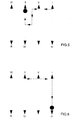
Figure 4 is a schematic view of the movements performed for engaging a first gear I in the double-clutch gearchange ofFigure 1 ; -
Figure 5 is a schematic view of the movements performed for engaging a second gear II in the double-clutch gearchange ofFigure 1 ; and -
Figure 6 is a schematic view of the movements performed for disengaging a first gear I and then engaging a third gear III in the double-clutch gearchange ofFigure 1 . - In
Figure 1 , the reference number 1 designates as a whole a servo transmission for an automobile (not illustrated) driven by an internal-combustion engine 2, which is provided with anengine shaft 3. - The servo transmission 1 comprises a servo double-
clutch gearchange 4, which is provided with a pair of primary shafts 5 coaxial to one another, independent of one another, and inserted inside one another. In addition, the double-clutch gearchange 4 comprises two coaxial clutches 6 set in series, each of which is designed to connect a respective primary shaft 5 to theengine shaft 3 of the internal-combustion engine 2. The double-clutch gearchange 4 comprises a singlesecondary shaft 7 connected to a differential (not illustrated) that transmits the motion to the drive wheels (not illustrated). - The double-
clutch gearchange 4 illustrated in the attached figure has six forward gears denoted by roman numbers (first gear I, second gear II, third gear III, fourth gear IV, fifth gear V, and sixth gear VI) and a reverse gear (denoted by the letter R). The primary shaft 5 and thesecondary shaft 7 are mechanically coupled to one another by means of a plurality of pairs of gears, each of which defines a respective gear speed and comprises aprimary gear wheel 8 mounted on the primary shaft 5 and asecondary gear wheel 9 mounted on thesecondary shaft 7. In order to enable proper operation of the double-clutch gearchange 4, all the odd gears (first gear I, third gear III, fifth gear V) are coupled to one and the sameprimary shaft 5b, whilst all the even gears (second gear II, fourth gear IV, and sixth gear VI) are coupled to the otherprimary shaft 5a. - Each
primary gear wheel 8 is fitted to a respective primary shaft 5 for rotating always in a fixed way with respect to the primary shaft 5 and meshes in a permanent way with the respectivesecondary gear wheel 9; instead, eachsecondary gear wheel 9 is mounted idle on thesecondary shaft 7. In addition, the double-clutch gearchange 4 comprises four synchronizers 10, each of which is mounted coaxial to thesecondary shaft 7, is set between twosecondary gear wheels 9, and is designed to be actuated for engaging alternatively the two respectivesecondary gear wheels 9 to the secondary shaft 7 (i.e., for rendering the two respectivesecondary gear wheels 9 alternatively angularly fixed with respect to the secondary shaft 7). In other words, each synchronizer 10 can be displaced in one direction to engage asecondary gear wheel 9 to thesecondary shaft 7, or else can be displaced in the other direction to engage the othersecondary gear wheel 9 to thesecondary shaft 7. - Each synchronizer 10 is set between two
secondary gear wheels 9 and is actuated by a respective fork 11 that displaces axially along thesecondary shaft 7 in the two directions for displacing the synchronizer 10 between two limit positions of engagement, in each of which the synchronizer 10 engages a respectivesecondary gear wheel 9, and an idle intermediate position, in which the synchronizer 10 does not engage either of the twosecondary gear wheels 9. In addition, each fork 11 is actuated by a finger 12 that is moved by acontrol shaft 13 of a singlecommon gear actuator 14. Thegear actuator 14 impresses upon the control shaft 13 a movement of axial translation (i.e., parallel to alongitudinal axis 15 of the control shaft 13) and a movement of rotation about thelongitudinal axis 15 of thecontrol shaft 13. - The four forks 11 are divided into two sets, each of which comprises two forks 11 and is actuated by a respective finger 12. In particular, the two
forks 11a that control the two synchronizers 10 coupled to thesecondary gear wheels 9 that mesh with theprimary gear wheels 8 of theprimary shaft 5a are actuated by afinger 12a, whilst the twoforks 11b that control the two synchronizers 10 coupled to thesecondary gear wheels 9 that mesh with theprimary gear wheels 8 of theprimary shaft 5b are actuated by afinger 12b separate from and independent of thefinger 12a. - According to what is illustrated in
Figure 2 , thecontrol shaft 13 is mounted in a rotatable and slidable way by means of a pair ofbearings 17 within a fixed box-like frame 16 of the double-clutch gearchange 4. One end of thecontrol shaft 13 comes out of theframe 16 to couple with thegear actuator 14 that is set on the outside of theframe 16. - Each finger 12 is carried by a tubular sleeve 18 fitted idle about the
control shaft 13 so as to be able to rotate and translate freely with respect to thecontrol shaft 13. Each sleeve 18 is pushed axially in the direction of the other sleeve 18 by a spring 19 that is set around the sleeve 18 and is compressed between a projection of theframe 16 and a projection of the sleeve 18 (for example, defined by the respective finger 12). The displacement of each sleeve 18 in the direction of the other sleeve 18 under the thrust of the spring 19 is limited by a detent 20, which is fixed to theframe 16 and defines an internal end-of-travel element for both of the sleeves 18. It should be noted that, when a sleeve 18 comes to bear upon thedetent 20 that defines the internal end-of-travel element, the respective finger 12 is found to be aligned with a respective internal fork 11 that controls an internal synchronizer 10 (i.e., set inwards) as illustrated inFigure 2 . In addition, the moving of each sleeve 18 away from the other sleeve 18 (and hence compressing the spring 19) is limited by the body of therespective bearing 17 that defines an external end-of-travel element for the sleeve 18. It should be noted that, when a sleeve 18 bears upon the body of therespective bearing 17 that defines the external end-of-travel element, the respective finger 12 is found to be aligned with a respective external fork 11 that controls an external synchronizer 10 (i.e., set towards the outside). In a different embodiment (not illustrated), the external end-of-travel elements of the sleeves 18 are not defined by thebearings 17, but by other detents fixed with respect to theframe 16. - In the area comprised between the two sleeves 18, a
pin 21 is provided, which is fixed with respect to thecontrol shaft 13, comes out radially (i.e., in a direction perpendicular to the longitudinal axis 15) from thecontrol shaft 13, and is designed to insert alternatively in each coupling slit 22 that is made in each sleeve 18 and reproduces in negative the shape of thepin 21. The ensemble of thepin 21 and the coupling slits 22 constitutes a coupling system, which is designed to render thecontrol shaft 13 alternatively angularly fixed with respect to the sleeves 18. It should be noted that the two sleeves 18 are axially separate from one another so as to define between them a free area. When thepin 21 comes to occupy the free area comprised between the two sleeves 18 (i.e., when thepin 21 is not inserted within a slit), thecontrol shaft 13 is angularly independent of the two sleeves 18 and can hence rotate freely with respect to the two sleeves 18 themselves. - Finally, each sleeve 18 comprises a retention device 23, which is preferably made with the known spring-ball architecture and is designed to maintain the sleeve 18 in the current angular position with a constant and predetermined retention torque. The function of each retention device 23 is to maintain the sleeve 18 in the current angular position preventing random, uncontrolled, and undesirable angular movements of the sleeve 18. Obviously, according to the modalities described in what follows, the
control shaft 13 is able to apply to eachsleeve 18 a torque that is sufficiently greater than the retention torque generated by the respective retention device 23 for guaranteeing the desired rotation of the sleeve 18. - The servo transmission 1 comprises a
control unit 24, which drives thegear actuator 14 for engaging/disengaging the gears, and drives the clutch actuators (not illustrated) that control opening and closing of the two clutches 6. - Operation of the double-
clutch gearchange 4 is described hereinafter with reference toFigures 2-6 . In particular, there follows a description of the modality of engagement of the first gear I starting from an idle condition (Figure 4 ), the subsequent modality of engagement of the second gear II (Figure 5 ), and finally the modality of disengagement of the first gear I and subsequent engagement of the third gear III (Figure 6 ). - Starting from an idle condition, in which no gear is engaged and the two clutches 6 are open (i.e., the
engine shaft 3 is disconnected from both of the primary shafts 5), thepin 21 is found in the intermediate position between the two coupling slits 22 illustrated inFigure 2 . To engage the first gear I, it is necessary to rotate theexternal fork 11a (the consequent movement of thepin 21 is illustrated schematically inFigure 4 ). Consequently, thegear actuator 14 displaces thecontrol shaft 13 axially so as to bring thepin 21 to insert into thecoupling slit 22a. Once thepin 21 of thecontrol shaft 13 is fitted within thecoupling slit 22a, thecontrol shaft 13 is angularly fixed with respect to thesleeve 18a. In this position, thefinger 12a carried by thesleeve 18a is aligned with theinternal fork 11a. Consequently, thegear actuator 14 axially displaces thecontrol shaft 13 to push thesleeve 18a so that it bears upon the external end-of-travel element so compressing thespring 19a in order to align thefinger 12a with theexternal fork 11a. - At this point, the
gear actuator 14 rotates thecontrol shaft 13 about thelongitudinal axis 15 so as to rotate thesleeve 18a, and hence thefinger 12a fixed with respect to thesleeve 18a and theexternal fork 11a pushed by thefinger 12a, in the direction necessary for engaging the first gear I. If it had been necessary to engage the third gear III, then thegear actuator 14 would have rotated thesleeve 18a in the opposite direction. As has been said previously, in rotating thesleeve 18a, thegear actuator 14 must overcome the retention torque generated by theretention device 23a. - Once the first gear I is engaged in the way described above, the clutch 6a can be closed for transmitting the motion from the
engine shaft 3 to the drive wheels (not illustrated) with the transmission ratio of the first gear I. In addition, once the first gear I has been engaged in the way described above, thegear actuator 14 acts for engaging also the second gear II rotating theinternal fork 11b (the consequent movement of thepin 21 is illustrated schematically inFigure 5 ). - In order to engage the second gear II, the
gear actuator 14 displaces thecontrol shaft 13 axially without performing any rotation so as to bring thepin 21 to be released from thecoupling slit 22a. This operation does not entail disengagement of the first gear I thanks to the retention torque exerted by theretention device 23a, which prevents thesleeve 18a from performing rotations except under the control of thegear actuator 14. Once thepin 21 has been disengaged from thecoupling slit 22a, thegear actuator 14 rotates thecontrol shaft 13 for aligning thepin 21 to thecoupling slit 22b and then impresses on the control shaft 13 a new axial displacement so as to bring thepin 21 to insert within thecoupling slit 22b. Once thepin 21 of thecontrol shaft 13 is fitted within thecoupling slit 22b, thecontrol shaft 13 is angularly fixed with respect to thesleeve 18b. In addition, in this position, thefinger 12b carried by thesleeve 18b is aligned with theinternal fork 11b that controls the internal synchronizer 10. At this point, thegear actuator 14 rotates thecontrol shaft 13 about thelongitudinal axis 15 for rotating thesleeve 18b, hence thefinger 12b fixed with respect to thesleeve 18b and theinternal fork 11b pushed by thefinger 12b, in the direction necessary for engaging the second gear II. If it had been necessary to engage the fourth gear IV, then thegear actuator 14 would have rotated thesleeve 18b in the opposite direction. As mentioned previously, in rotating thesleeve 18b, thegear actuator 14 must overcome the retention torque generated by theretention device 23b. - Once the second gear II has been engaged in the way described above, the clutch 6b can be closed, and simultaneously the clutch 6a must be opened for transmitting the motion from the
engine shaft 3 to the drive wheels (not illustrated) with the transmission ratio of the second gear II. In addition, once the second gear II has been engaged in the way described above, thegear actuator 14 acts for disengaging the first gear I and then engaging the third gear III by rotating theexternal fork 11a (the consequent movement of thepin 21 is illustrated schematically inFigure 6 ). - For disengaging the first gear I and then engaging the third gear III, the
gear actuator 14 axially displaces thecontrol shaft 13 without performing any rotation so as to bring thepin 21 to be released from thecoupling slit 22b and then inserted in thecoupling slit 22a. This operation does not entail disengagement of the second gear II thanks to the retention torque exerted by theretention device 23b, which prevents thesleeve 18b from performing any rotation except under the thrust of thegear actuator 14. Once thepin 21 of thecontrol shaft 13 is fitted within thecoupling slit 22a, thecontrol shaft 13 is angularly fixed with respect to thesleeve 18a. In addition, in this position, thefinger 12a carried by thesleeve 18a is aligned with theexternal fork 11a that controls theexternal synchronizer 10a. At this point, thegear actuator 14 rotates thecontrol shaft 13 about thelongitudinal axis 15 for rotating thesleeve 18a, hence thefinger 12a fixed with respect to thesleeve 18a and theexternal fork 11a pushed by thefinger 12a, in the direction necessary for disengaging the first gear I (which is not involved in the transmission of the torque in so far as the clutch 6a is open) and hence for engaging the third gear III. As mentioned previously, in rotating thesleeve 18a, thegear actuator 14 must overcome the retention torque generated by theretention device 23a. - Once the third gear III has been engaged in the way described above, the clutch 6a can be closed, and simultaneously the clutch 6b must be opened for transmitting the motion from the
engine shaft 3 to the drive wheels (not illustrated) with the transmission ratio of the third gear III. - The double-
clutch gearchange 4 described above presents numerous advantages in so far as it is simple, inexpensive and compact, and requires the use of just onegear actuator 14 that is able to actuate all the forks 11 in an efficient and effective way.
Claims (14)
- A double-clutch gearchange (4) comprising:two primary shafts (5);a secondary shaft (7);a plurality of pairs of gear wheels (8, 9), each of which couples mechanically the primary shaft (5) to the secondary shaft (7), defines a respective gear speed and comprises a primary gear wheel (8) mounted on the primary shaft (5) and a secondary gear wheel (9) that is mounted on the secondary shaft (7) and meshes permanently with the primary gear wheel (8);a plurality of synchronizers (10), each of which is mounted coaxial to a shaft (5; 7) between two gear wheels (8; 9) of two pairs of gears and is designed to be actuated for engaging alternatively the two gear wheels (8; 9) to the shaft (5; 7);a plurality of forks (11), which actuate the synchronizers (10) and are divided into two distinct groups, each of which is associated to a respective primary shaft (5); andtwo fingers (12), each of which is associated to a set of forks (11) for actuating all and exclusively the forks (11) of the set of forks (11);the double-clutch gearchange (4) being characterized in that it comprises:a single control shaft (13) mounted so that it can turn about a longitudinal axis (15) and axially slidable along the longitudinal axis (15);a single gear actuator (14) connected to the control shaft (13) for rotating the control shaft (13) about the longitudinal axis (15) and for displacing the control shaft (13) axially along the longitudinal axis (15);two sleeves (18), each of which supports a respective finger (12) and is fitted idle about the control shaft (13) so as to be able to rotate and translate freely with respect to the control shaft (13); anda coupling system, which is designed to render the control shaft (13) alternatively angularly fixed with respect to the sleeves (18).
- The double-clutch gearchange (4) according to Claim 1, wherein the coupling system comprises:two coupling slits (22), each of which is made in a respective sleeve (18); anda pin (21), which is fixed with respect to the control shaft (13), comes radially out from the control shaft (13), and is designed to insert alternatively in each coupling slit (22).
- The double-clutch gearchange (4) according to Claim 2, wherein the two slits reproduce in negative the shape of the pin (21) and are set facing one another.
- The double-clutch gearchange (4) according to Claim 2 or Claim 3, wherein the two sleeves (18) are axially separate from one another so as to define between the two sleeves (18) themselves a free area.
- The double-clutch gearchange (4) according to Claim 4, wherein, when the pin (21) comes to be in the free area comprised between the two sleeves (18), the control shaft (13) is angularly independent of the two sleeves (18) and can hence rotate freely with respect to the two sleeves (18) themselves.
- The double-clutch gearchange (4) according to any one of Claims 1 to 5 and comprising two springs (19), each of which pushes a respective sleeve (18) towards the other sleeve (18).
- The double-clutch gearchange (4) according to Claim 6, wherein each spring (19) is set around the respective sleeve (18) and is compressed between a projection of a fixed frame (16) that houses the control shaft (13) and a projection of the sleeve (18).
- The double-clutch gearchange (4) according to Claim 6 or Claim 7, and comprising for each sleeve (18) an internal end-of-travel element, which limits the displacement of each sleeve (18) in the direction of the other sleeve (18) under the thrust of the spring (19).
- The double-clutch gearchange (4) according to Claim 8, wherein the two internal end-of-travel elements are defined by one and the same detent (20) fixed with respect to a fixed frame (16) that houses the control shaft (13).
- The double-clutch gearchange (4) according to Claim 8 or Claim 9, wherein, when each sleeve (18) bears upon the internal end-of-travel element, the respective finger (12) is aligned with an internal fork (11).
- The double-clutch gearchange (4) according to any one of Claims 1 to 10 and comprising for each sleeve (18) an external end-of-travel element, which limits the displacement of each sleeve (18) as it moves away from the other sleeve (18).
- The double-clutch gearchange (4) according to Claim 11, wherein each external end-of-travel element is defined by a body of a bearing (17) that is carried by a fixed frame (16) that houses the control shaft (13) and supports the control shaft (13) in a rotatable and slidable way.
- The double-clutch gearchange (4) according to Claim 11 or Claim 12, wherein, when each sleeve (18) bears upon the external end-of-travel element, the respective finger (12) is aligned with an external fork (11).
- The double-clutch gearchange (4) according to any one of Claims 1 to 13 and comprising two retention devices (23), each of which is designed to maintain a respective sleeve (18) in the current angular position with a constant and predetermined retention torque.
Priority Applications (5)
| Application Number | Priority Date | Filing Date | Title |
|---|---|---|---|
| EP08425335A EP2143979B1 (en) | 2008-05-13 | 2008-05-13 | Double-clutch gearchange |
| RU2009118017/11A RU2495300C2 (en) | 2008-05-13 | 2009-05-12 | Gear shifting mechanism with double coupling |
| US12/464,397 US20090293657A1 (en) | 2008-05-13 | 2009-05-12 | Double-clutch gearchange |
| BRPI0901705A BRPI0901705B8 (en) | 2008-05-13 | 2009-05-12 | gearbox with double clutch |
| CN200910203809.3A CN101581361B (en) | 2008-05-13 | 2009-05-13 | Double-clutch gearchange |
Applications Claiming Priority (1)
| Application Number | Priority Date | Filing Date | Title |
|---|---|---|---|
| EP08425335A EP2143979B1 (en) | 2008-05-13 | 2008-05-13 | Double-clutch gearchange |
Publications (2)
| Publication Number | Publication Date |
|---|---|
| EP2143979A1 true EP2143979A1 (en) | 2010-01-13 |
| EP2143979B1 EP2143979B1 (en) | 2012-02-08 |
Family
ID=39734090
Family Applications (1)
| Application Number | Title | Priority Date | Filing Date |
|---|---|---|---|
| EP08425335A Ceased EP2143979B1 (en) | 2008-05-13 | 2008-05-13 | Double-clutch gearchange |
Country Status (5)
| Country | Link |
|---|---|
| US (1) | US20090293657A1 (en) |
| EP (1) | EP2143979B1 (en) |
| CN (1) | CN101581361B (en) |
| BR (1) | BRPI0901705B8 (en) |
| RU (1) | RU2495300C2 (en) |
Cited By (4)
| Publication number | Priority date | Publication date | Assignee | Title |
|---|---|---|---|---|
| ITRM20100253A1 (en) * | 2010-05-17 | 2011-11-18 | Magneti Marelli Spa | DOUBLE CLUTCH CHANGE |
| EP2690323A1 (en) * | 2009-06-17 | 2014-01-29 | Scania CV AB | Device for the automatic operation of a manual gear box |
| DE102013004953A1 (en) * | 2013-03-22 | 2014-09-25 | Audi Ag | Actuator device for a transmission of a motor vehicle and corresponding transmission of a motor vehicle |
| EP4248110B1 (en) * | 2020-11-18 | 2026-04-22 | Robert Bosch GmbH | Transmission with a coupling device for coupling and/or uncoupling a gearwheel to or from a shaft |
Families Citing this family (4)
| Publication number | Priority date | Publication date | Assignee | Title |
|---|---|---|---|---|
| DE102011119833B4 (en) * | 2011-12-01 | 2019-08-29 | Audi Ag | Switching device for dual-clutch transmission in motor vehicles |
| DE102012100870B4 (en) * | 2011-12-29 | 2014-07-31 | Getrag Ford Transmissions Gmbh | Switching device for a manual transmission |
| IT201700054752A1 (en) * | 2017-05-19 | 2018-11-19 | Magneti Marelli Spa | DRIVING DEVICE FOR A DRIVE SHAFT OF A SERVO-CHANGE |
| CN113624107B (en) * | 2021-06-30 | 2023-06-16 | 眉山中车制动科技股份有限公司 | Altitude valve and main shaft composition detection device thereof |
Citations (7)
| Publication number | Priority date | Publication date | Assignee | Title |
|---|---|---|---|---|
| FR2089271A5 (en) * | 1970-04-06 | 1972-01-07 | Int Harvester Co | |
| DE4115675A1 (en) * | 1990-05-30 | 1992-02-06 | Bratislavske Automobilobe Z Ak | Stepped ratio vehicle gearbox - uses single control shaft in guide tube with blocking balls and pins engaging forks |
| JPH07332490A (en) * | 1994-06-10 | 1995-12-22 | Aisin Ee I Kk | Shift control mechanism for manual transmission |
| DE19920064A1 (en) * | 1999-05-03 | 2000-11-16 | Daimler Chrysler Ag | Gear wheel discrete gearbox for motor vehicle has change rod movable w.r.t change body in first state, coupled to change body in second state by electromagnetically actuated coupling element |
| DE10108881A1 (en) * | 2001-02-23 | 2002-09-05 | Volkswagen Ag | Dual clutch gearbox has two gearbox parts and single shift shaft axially displaced and rotated by selection actuator and shift actuator with shift shaft connecting to shift rod of one gearbox part without disengaging previously engaged gear |
| FR2848629A1 (en) * | 2002-12-12 | 2004-06-18 | Renault Sa | MECHANICAL GEARBOX WITH COAXIAL PRIMARY SHAFTS AND METHODS OF CONTROLLING THE SAME. |
| WO2007065611A1 (en) * | 2005-12-07 | 2007-06-14 | H.C.F. Porsche Aktiengesellschaft | Actuating device for a transmission having a plurality of gear stages |
Family Cites Families (17)
| Publication number | Priority date | Publication date | Assignee | Title |
|---|---|---|---|---|
| SU1062034A1 (en) * | 1982-09-20 | 1983-12-23 | Lifshits Isaak | Ten-speed transmission |
| US4569247A (en) * | 1982-12-15 | 1986-02-11 | Toyota Jidosha Kabushiki Kaisha | Detent mechanism in manual transmission |
| SU1169845A1 (en) * | 1984-05-04 | 1985-07-30 | Lifshits Isaak | Method of vehicle transmission |
| FR2615798B1 (en) * | 1987-05-25 | 1989-09-15 | Peugeot | CONTROL DEVICE FOR A MOTOR VEHICLE GEARBOX |
| FR2733020B1 (en) * | 1995-04-14 | 1997-05-09 | Peugeot | INTERNAL GEARBOX CONTROL WITH SELECTION DEVICE RECALL |
| RU2082625C1 (en) * | 1995-08-04 | 1997-06-27 | Акционерное общество "АвтоВАЗ" | Vehicle gearshift mechanism |
| US5737969A (en) * | 1996-04-22 | 1998-04-14 | Eaton Corporation | Single shaft shifting mechanism |
| GB0226934D0 (en) * | 2002-11-19 | 2002-12-24 | Luk Lamellen & Kupplungsbau | Gear engagement mechanism |
| EP1651513A4 (en) * | 2003-07-21 | 2008-09-03 | Nautitech Pty Ltd | Dual speed transmission |
| GB0319705D0 (en) * | 2003-08-21 | 2003-09-24 | Ricardo Uk Ltd | Gear selector mechanisms |
| US7219571B2 (en) * | 2004-11-15 | 2007-05-22 | Borgwarner, Inc. | Transmission having an electro-mechanical gear actuation system |
| JP4970753B2 (en) * | 2005-08-03 | 2012-07-11 | 日産自動車株式会社 | Automatic manual transmission shift control device |
| US7467564B2 (en) * | 2006-03-13 | 2008-12-23 | Ford Global Technologies, Llc | Actuator mechanism for shift motors of a transmission |
| US7455619B2 (en) * | 2006-05-10 | 2008-11-25 | Ford Global Technologies, Llc | Control strategy for avoiding tip-in noise in a powershift transmission |
| JP4696221B2 (en) * | 2007-03-01 | 2011-06-08 | 三菱自動車工業株式会社 | Synchronous meshing automatic transmission |
| US7845247B2 (en) * | 2007-05-30 | 2010-12-07 | Gm Global Technology Operations, Inc. | Shift fork actuation system for control of synchronizer position |
| KR100957146B1 (en) * | 2007-12-03 | 2010-05-11 | 현대자동차주식회사 | Double clutch transmission |
-
2008
- 2008-05-13 EP EP08425335A patent/EP2143979B1/en not_active Ceased
-
2009
- 2009-05-12 US US12/464,397 patent/US20090293657A1/en not_active Abandoned
- 2009-05-12 BR BRPI0901705A patent/BRPI0901705B8/en not_active IP Right Cessation
- 2009-05-12 RU RU2009118017/11A patent/RU2495300C2/en active
- 2009-05-13 CN CN200910203809.3A patent/CN101581361B/en not_active Expired - Fee Related
Patent Citations (7)
| Publication number | Priority date | Publication date | Assignee | Title |
|---|---|---|---|---|
| FR2089271A5 (en) * | 1970-04-06 | 1972-01-07 | Int Harvester Co | |
| DE4115675A1 (en) * | 1990-05-30 | 1992-02-06 | Bratislavske Automobilobe Z Ak | Stepped ratio vehicle gearbox - uses single control shaft in guide tube with blocking balls and pins engaging forks |
| JPH07332490A (en) * | 1994-06-10 | 1995-12-22 | Aisin Ee I Kk | Shift control mechanism for manual transmission |
| DE19920064A1 (en) * | 1999-05-03 | 2000-11-16 | Daimler Chrysler Ag | Gear wheel discrete gearbox for motor vehicle has change rod movable w.r.t change body in first state, coupled to change body in second state by electromagnetically actuated coupling element |
| DE10108881A1 (en) * | 2001-02-23 | 2002-09-05 | Volkswagen Ag | Dual clutch gearbox has two gearbox parts and single shift shaft axially displaced and rotated by selection actuator and shift actuator with shift shaft connecting to shift rod of one gearbox part without disengaging previously engaged gear |
| FR2848629A1 (en) * | 2002-12-12 | 2004-06-18 | Renault Sa | MECHANICAL GEARBOX WITH COAXIAL PRIMARY SHAFTS AND METHODS OF CONTROLLING THE SAME. |
| WO2007065611A1 (en) * | 2005-12-07 | 2007-06-14 | H.C.F. Porsche Aktiengesellschaft | Actuating device for a transmission having a plurality of gear stages |
Cited By (6)
| Publication number | Priority date | Publication date | Assignee | Title |
|---|---|---|---|---|
| EP2690323A1 (en) * | 2009-06-17 | 2014-01-29 | Scania CV AB | Device for the automatic operation of a manual gear box |
| ITRM20100253A1 (en) * | 2010-05-17 | 2011-11-18 | Magneti Marelli Spa | DOUBLE CLUTCH CHANGE |
| DE102013004953A1 (en) * | 2013-03-22 | 2014-09-25 | Audi Ag | Actuator device for a transmission of a motor vehicle and corresponding transmission of a motor vehicle |
| EP2976555B1 (en) * | 2013-03-22 | 2020-01-15 | Audi AG | Actuator device for a gearbox of a motor vehicle and corresponding gearbox for a motor vehicle |
| US10746292B2 (en) | 2013-03-22 | 2020-08-18 | Audi Ag | Actuator device for a gearbox of a motor vehicle and corresponding gearbox for a motor vehicle |
| EP4248110B1 (en) * | 2020-11-18 | 2026-04-22 | Robert Bosch GmbH | Transmission with a coupling device for coupling and/or uncoupling a gearwheel to or from a shaft |
Also Published As
| Publication number | Publication date |
|---|---|
| EP2143979B1 (en) | 2012-02-08 |
| US20090293657A1 (en) | 2009-12-03 |
| BRPI0901705A2 (en) | 2010-01-26 |
| RU2009118017A (en) | 2010-11-20 |
| BRPI0901705B1 (en) | 2020-09-08 |
| RU2495300C2 (en) | 2013-10-10 |
| BRPI0901705B8 (en) | 2021-02-09 |
| CN101581361A (en) | 2009-11-18 |
| CN101581361B (en) | 2014-10-29 |
Similar Documents
| Publication | Publication Date | Title |
|---|---|---|
| EP2143979B1 (en) | Double-clutch gearchange | |
| US7661331B2 (en) | Shifting device for dual clutch transmission | |
| EP2042783B1 (en) | Twin clutch type speed-change apparatus | |
| EP3120045B1 (en) | Heavy duty transmission architecture | |
| CN102588522B (en) | Eight speed dual clutch transmissions | |
| US20150096393A1 (en) | Power transmitting apparatus for vehicle | |
| DE102010012134A1 (en) | Gear box switching device e.g. automated gear box switching device, for use in drive train device for driving motor car, has drum switch comprising clutch rolling path designed as recess to operate load clutch element | |
| CN104913050B (en) | Gear shift arrangement and shifting method for motor-vehicle gearbox | |
| EP1400724B1 (en) | Transmission | |
| US20100242657A1 (en) | Dual clutch transmission | |
| US9719564B2 (en) | Synchronizer re-energization for improved cold shift comfort | |
| EP2189681B1 (en) | Double-clutch gearbox | |
| EP2110578A2 (en) | Dual clutch type automated transmission apparatus | |
| EP2372199B1 (en) | Automatic manual transmission provided with parking lock device | |
| EP2372197B1 (en) | Device for selecting and displacing actuating elements of a gear-box for motor-vehicles | |
| CN107664177B (en) | Transmission for vehicle | |
| EP3818277B1 (en) | Lay-shaft assembly for use in a vehicle transmission | |
| US8172715B2 (en) | Multiplexed gear actuation system for a dual clutch transmission | |
| JPH07127739A (en) | Electronically controlled transmission | |
| JP6288122B2 (en) | Manual transmission | |
| CN213744867U (en) | An automatic transmission shifting device | |
| JP2006070929A (en) | Selectively meshing gear mechanism for vehicle transmission | |
| EP1830112A1 (en) | Transmission unit provided with a control device for a motor vehicle | |
| JP2025054492A (en) | Vehicle transmission | |
| EP2116745A1 (en) | Electric servo-control for a servo-assited gearbox |
Legal Events
| Date | Code | Title | Description |
|---|---|---|---|
| PUAI | Public reference made under article 153(3) epc to a published international application that has entered the european phase |
Free format text: ORIGINAL CODE: 0009012 |
|
| 17P | Request for examination filed |
Effective date: 20091015 |
|
| AK | Designated contracting states |
Kind code of ref document: A1 Designated state(s): AT BE BG CH CY CZ DE DK EE ES FI FR GB GR HR HU IE IS IT LI LT LU LV MC MT NL NO PL PT RO SE SI SK TR |
|
| AX | Request for extension of the european patent |
Extension state: AL BA MK RS |
|
| AKX | Designation fees paid |
Designated state(s): DE FR IT |
|
| GRAP | Despatch of communication of intention to grant a patent |
Free format text: ORIGINAL CODE: EPIDOSNIGR1 |
|
| RAP1 | Party data changed (applicant data changed or rights of an application transferred) |
Owner name: MAGNETI MARELLI S.P.A. |
|
| GRAS | Grant fee paid |
Free format text: ORIGINAL CODE: EPIDOSNIGR3 |
|
| GRAA | (expected) grant |
Free format text: ORIGINAL CODE: 0009210 |
|
| AK | Designated contracting states |
Kind code of ref document: B1 Designated state(s): DE FR IT |
|
| REG | Reference to a national code |
Ref country code: DE Ref legal event code: R096 Ref document number: 602008013238 Country of ref document: DE Effective date: 20120405 |
|
| PLBE | No opposition filed within time limit |
Free format text: ORIGINAL CODE: 0009261 |
|
| STAA | Information on the status of an ep patent application or granted ep patent |
Free format text: STATUS: NO OPPOSITION FILED WITHIN TIME LIMIT |
|
| 26N | No opposition filed |
Effective date: 20121109 |
|
| REG | Reference to a national code |
Ref country code: DE Ref legal event code: R097 Ref document number: 602008013238 Country of ref document: DE Effective date: 20121109 |
|
| REG | Reference to a national code |
Ref country code: FR Ref legal event code: PLFP Year of fee payment: 9 |
|
| REG | Reference to a national code |
Ref country code: FR Ref legal event code: PLFP Year of fee payment: 10 |
|
| REG | Reference to a national code |
Ref country code: FR Ref legal event code: PLFP Year of fee payment: 11 |
|
| PGFP | Annual fee paid to national office [announced via postgrant information from national office to epo] |
Ref country code: DE Payment date: 20240418 Year of fee payment: 17 |
|
| PGFP | Annual fee paid to national office [announced via postgrant information from national office to epo] |
Ref country code: IT Payment date: 20240418 Year of fee payment: 17 Ref country code: FR Payment date: 20240418 Year of fee payment: 17 |
|
| REG | Reference to a national code |
Ref country code: DE Ref legal event code: R119 Ref document number: 602008013238 Country of ref document: DE |
|
| PG25 | Lapsed in a contracting state [announced via postgrant information from national office to epo] |
Ref country code: DE Free format text: LAPSE BECAUSE OF NON-PAYMENT OF DUE FEES Effective date: 20251202 |
|
| PG25 | Lapsed in a contracting state [announced via postgrant information from national office to epo] |
Ref country code: IT Free format text: LAPSE BECAUSE OF NON-PAYMENT OF DUE FEES Effective date: 20250513 |
|
| PG25 | Lapsed in a contracting state [announced via postgrant information from national office to epo] |
Ref country code: FR Free format text: LAPSE BECAUSE OF NON-PAYMENT OF DUE FEES Effective date: 20250531 |