EP2143911A2 - Brennstoffzufuhrsystem für ein Gasturbinentriebwerk - Google Patents
Brennstoffzufuhrsystem für ein Gasturbinentriebwerk Download PDFInfo
- Publication number
- EP2143911A2 EP2143911A2 EP09164127A EP09164127A EP2143911A2 EP 2143911 A2 EP2143911 A2 EP 2143911A2 EP 09164127 A EP09164127 A EP 09164127A EP 09164127 A EP09164127 A EP 09164127A EP 2143911 A2 EP2143911 A2 EP 2143911A2
- Authority
- EP
- European Patent Office
- Prior art keywords
- fuel
- valves
- valve
- pilot
- main
- Prior art date
- Legal status (The legal status is an assumption and is not a legal conclusion. Google has not performed a legal analysis and makes no representation as to the accuracy of the status listed.)
- Granted
Links
- 239000000446 fuel Substances 0.000 title claims abstract description 125
- 238000002347 injection Methods 0.000 claims description 6
- 239000007924 injection Substances 0.000 claims description 6
- 238000001816 cooling Methods 0.000 claims description 3
- 230000000903 blocking effect Effects 0.000 claims 1
- 230000001276 controlling effect Effects 0.000 claims 1
- 230000001105 regulatory effect Effects 0.000 claims 1
- 241001156002 Anthonomus pomorum Species 0.000 description 4
- 238000012423 maintenance Methods 0.000 description 4
- 238000002485 combustion reaction Methods 0.000 description 3
- 238000011144 upstream manufacturing Methods 0.000 description 3
- 238000004939 coking Methods 0.000 description 2
- 230000015572 biosynthetic process Effects 0.000 description 1
- 238000003763 carbonization Methods 0.000 description 1
- 230000001419 dependent effect Effects 0.000 description 1
- 238000011010 flushing procedure Methods 0.000 description 1
- 125000000524 functional group Chemical group 0.000 description 1
- 238000010438 heat treatment Methods 0.000 description 1
- 238000009434 installation Methods 0.000 description 1
Images



Classifications
-
- F—MECHANICAL ENGINEERING; LIGHTING; HEATING; WEAPONS; BLASTING
- F02—COMBUSTION ENGINES; HOT-GAS OR COMBUSTION-PRODUCT ENGINE PLANTS
- F02C—GAS-TURBINE PLANTS; AIR INTAKES FOR JET-PROPULSION PLANTS; CONTROLLING FUEL SUPPLY IN AIR-BREATHING JET-PROPULSION PLANTS
- F02C7/00—Features, components parts, details or accessories, not provided for in, or of interest apart form groups F02C1/00 - F02C6/00; Air intakes for jet-propulsion plants
- F02C7/22—Fuel supply systems
- F02C7/232—Fuel valves; Draining valves or systems
-
- F—MECHANICAL ENGINEERING; LIGHTING; HEATING; WEAPONS; BLASTING
- F02—COMBUSTION ENGINES; HOT-GAS OR COMBUSTION-PRODUCT ENGINE PLANTS
- F02C—GAS-TURBINE PLANTS; AIR INTAKES FOR JET-PROPULSION PLANTS; CONTROLLING FUEL SUPPLY IN AIR-BREATHING JET-PROPULSION PLANTS
- F02C9/00—Controlling gas-turbine plants; Controlling fuel supply in air- breathing jet-propulsion plants
- F02C9/26—Control of fuel supply
- F02C9/263—Control of fuel supply by means of fuel metering valves
-
- Y—GENERAL TAGGING OF NEW TECHNOLOGICAL DEVELOPMENTS; GENERAL TAGGING OF CROSS-SECTIONAL TECHNOLOGIES SPANNING OVER SEVERAL SECTIONS OF THE IPC; TECHNICAL SUBJECTS COVERED BY FORMER USPC CROSS-REFERENCE ART COLLECTIONS [XRACs] AND DIGESTS
- Y02—TECHNOLOGIES OR APPLICATIONS FOR MITIGATION OR ADAPTATION AGAINST CLIMATE CHANGE
- Y02T—CLIMATE CHANGE MITIGATION TECHNOLOGIES RELATED TO TRANSPORTATION
- Y02T50/00—Aeronautics or air transport
- Y02T50/60—Efficient propulsion technologies, e.g. for aircraft
Definitions
- the invention relates to a fuel supply system for a gas turbine engine having a high-pressure feed line, a fuel metering unit and a fuel distributor system connected to the burners for controlling the amount of fuel supplied to the individual burners.
- Multi-line fuel supply systems which comprise a high pressure supply line arranged in the cold region of the engine with a fuel metering unit and a fuel staging unit.
- the staging unit splits the metered fuel flow to at least one main burner line and to a pilot burner line, which are in the hot area of the engine and are connected to the main nozzles or pilot nozzles of the individual burners.
- the US 6813876 B2 describes a fuel supply system for a gas turbine engine having a main burner fuel supply line and a pilot burner fuel supply line.
- a high pressure pump supplies the fuel to the main and pilot burner supply lines.
- a throttle valve regulates the fuel flow in the main burner supply line, while a metering valve regulates the fuel flow in the pilot burner supply line.
- the arrangement provided here of two-part fuel line systems with the pilot and the main nozzles of the individual burner separately associated supply lines or the formation of several provided with control valves supply lines for the main burner for variable supply of burners with fuel is disadvantageous in that when switching off certain burner groups Fuel in the temporarily shut down, located in the hot area of the engine lines and thereby parts of the fuel system can be blocked due to carbonization of the fuel, so that an exact, with the conventional - for example, mechanical or pneumatic - valve drives anyway difficult regulation of the fuel supply to the individual burners or groups of burners and a continuous, low-emission combustion is not guaranteed unless further measures are taken to cool the stationary fuel in the hot area, which in turn would be associated with disadvantages such as increased weight.
- a known multi-stage gas turbine engine fueling system comprises a plurality of burners and at least first and second fuel injection circuits in each burner, and first and second fuel nozzle valves in each burner controllably connected to the fuel injector circuits of the respective burner. All burners are supplied with the fuel to be combusted by a single fuel supply line, wherein the control of the valves via a signal fuel line is carried out hydraulically by a differential pressure to the fuel pressure in the fuel supply line.
- the system described is complicated and also disadvantageous in that the heating of the fuel in the signal circuit is associated with the above-described problems.
- the fuel supply via graduated valves which also detailed in the US 7007476 B2 Be described, is also expensive in terms of equipment and limited in the grading functionality.
- the invention is based on the object, a simply formed fuel supply system for a gas turbine engine specify that ensures an exact variable fuel distribution or metering on the individual stepped or unampled burner and thus a stable, low-emission combustion with low weight and small size of the valves and also low maintenance and has a long life.
- the basic idea of the invention resides in a fuel distributor system assigned to the plurality of burners, which in the hot engine compartment only has a single fuel line (individual fuel line) and a shut-off valve assigned to each burner and consisting of several independently, individually or simultaneously electrically adjustable into a closed or open end position. Pilot and / or main valves) existing valve device comprises.
- the check valves have a certain (constant) but different from valve to valve cross-section, so that according to the on / off switching state of the check valve valves a certain - variable fuel distribution to the individual burner and between the stages (pilot and main injector) one and the same burner can be done.
- the thus formed - electrically actuated - valve combination (two- or multi-state valve) is low in wear and maintenance and ensures a stable, adapted to the respective operating and flight conditions combustion without coking in the fuel distribution system and long service life of the components of the distribution system.
- the electrically operated shut-off valves which can be lapped around for cooling by the fuel, each connected to a single signal line to be able to be adjusted independently. However, they are connected to a common return line, which can also be used as an alternative signal line, so that the installation cost is low and the weight can be kept low.
- provided for fuel distribution and / or metering valve devices can also be controlled independently or in groups, with functional groups of valves can use common signal or return lines.
- the valve device comprises a graduated valve device designed for stepped burners, which includes at least one pilot valve or main valve. According to the respective switching position (open or closed) of the pilot and main valves, the fuel flow can be divided between the pilot and main injectors of the stepped burner.
- the pilot valve can be designed so that it opens or closes a larger cross-section and leaves a smaller cross-section in the closed state.
- the valve device is designed as a binary distribution device and comprises for fuel distribution to a stepped burner at least two pilot valves and / or at least two main valves, which are dimensioned in cross section so that each valve is twice as large as the previous one.
- the binary distribution valve means can simultaneously function as a fuel metering valve means for the respective stepped burners, so that the fuel metering unit in the high-pressure supply line can be omitted, thus reducing the cost and weight of the fuel supply system.
- non-stepped burners are formed with a binary metering valve device consisting of a plurality of check valves with a binary coded cross-sectional size.
- individual or all check valves are designed so that in the currentless case (fault) either the last valve position is maintained, or the valve occupies a defined position.
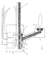
- Fig. 1 shown fuel supply system comprises a high pressure supply line 1, in which a fuel metering unit 2 is integrated and which opens into a lying in the hot engine compartment single fuel line 3.
- a fuel metering unit 2 is integrated and which opens into a lying in the hot engine compartment single fuel line 3.
- a plurality of stepped burners 4 each including a pilot injector 5 and a main injector 6.
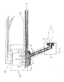
- Each such stepped burner 4 is one with that of the Brennstoffdosierü 2 via assigned to the Binzelbrennstofftechnisch 3 supplied fuel impinged Stufungsventil observed 7, which is lapped around the fuel for cooling and, as Fig. 2 can be formed by a pilot valve 8 and a first and a second main valve 9 and 10.
- the pilot valve 8 and the main valves 9, 10 of the Stufungsventil worn 7 can be adjusted via mutually insulated signal lines 11 and a common return line 12 - preferably electromagnetically or piezoelectric - in an upper and a lower end position, that is in an open position and a closed position.
- a common return line 12 - preferably electromagnetically or piezoelectric - in an upper and a lower end position, that is in an open position and a closed position.
- Fig. 3 Various switching states of the Stufungsventil worn 7 are shown for adjusting the ratio between the pilot injection nozzle 5 and the main injector 6 amount of fuel supplied.
- a defined fuel flow flows through the individual fuel line 3 to the graduated valve device 7 and therefore the pressure in the line changes depending on the switching state of the check valves.
- a pilot valve 8 located in the upper end position, a maximum possible fuel flow reaches the pilot injection nozzle 5 of the burner 4 and no fuel to the main injector 6.
- the switching state shown are the three staging valves (check valves 8, 9, 10) in the upper end position (open position), so that the fuel volume flowing to the main injection nozzle 6 further increases and the fuel flow to the pilot injector 5 is further reduced.
- the switching state after Fig. 3e is only the pilot valve 8 in the lower end position, so that passes over the small cross-section A 0 only a very small fuel flow to the pilot injector 5, while the main injector 6 is supplied with a maximum amount of fuel.
- a single fuel line 3 with upstream Brennstoffdosieriki 2 associated Stufungsventil worn 7 for the respective burner 4 can each with only two switching positions (upper / lower end position) of the individual Stufungsventile (check valves) different ratios between the pilot injector 5 and the main injector. 6 supplied amount of fuel can be adjusted.
- the Stufungsventil adopted 7 has due to the only two switching positions of the check valves on a very good zero stability and can be created due to the here usable - easily trained and individually electrically actuated - check valves with little effort and low-maintenance and wear-resistant, that is, with a long service life, to be operated.
- shut-off valves which close quickly and tightly in a very short time, also reduce the switch-off time during shaft breakage. Since the check valves are located in the hot area of the gas turbine engine, heat removal is required, but this can be achieved by flushing the valves with the fuel. As in the hot engine area only one (single) is constantly provided with fuel flowing through individual fuel line, clogging of this fuel line due to coking is not to be feared.
- the fuel supply to the stepped burner 4, that is to the pilot injector 5 and the main injector 6, using a associated with each burner 4 and integrated into a single fuel line 3 binary distribution valve device 13 are solved, which also mentioned in the previously described Stufungsventil worn 7, simple having trained and controllable, low-wear and low-maintenance electrical pilot and main valves (check valves) for adjusting the size of the pilot injector 5 and the main injector 6 to be supplied fuel flow.
- the binary distribution valve device 13 includes in the in Fig.
- binary first to third main valves 16, 17 and 18 are provided, the three different release large sections A 6 , A 7 and A 8 or close.
- the cross sections A 7 and A 8 are twice or four times as large as the cross section A 6 , so that according to the switching position of the main valves 16 to 18 a binary coded Brennstoffzu limp to the main injector 6 is possible.
- Fig. 6 shows still a corresponding Binärdosierventil raised 19 with n binary valves 22, 23, 24, 25, etc. for an unampled burner 20 with only one injector 21.
- a trained with a sufficiently large number of binary valves Binärdosierventil boots 19 takes over the function of the above-described embodiments yet required fuel metering unit 2.
Landscapes
- Engineering & Computer Science (AREA)
- Chemical & Material Sciences (AREA)
- Combustion & Propulsion (AREA)
- Mechanical Engineering (AREA)
- General Engineering & Computer Science (AREA)
- Feeding And Controlling Fuel (AREA)
Abstract
Description
- Die Erfindung betrifft ein Brennstoffzufuhrsystem für ein Gasturbinentriebwerk mit einer Hochdruckzufuhrleitung, einer Brennstoffdosiereinheit und einem mit den Brennern verbundenen Brennstoffverteilersystem zur Regelung der den einzelnen Brennern zugeführten Brennstoffmenge.
- Es sind beispielsweise aus der
US 7137242 B2 Mehrleitungsbrennstoffzufuhrsysteme bekannt, die eine im kalten Bereich des Triebwerks angeordnete Hochdruckzufuhrleitung mit einer Brennstoffdosiereinheit und einer Brennstoffstufungseinheit umfassen. Die Stufungseinheit teilt den dosierten Brennstoffstrom auf mindestens eine Hauptbrennerleitung und auf eine Pilotbrennerleitung auf, die im heißen Bereich des Triebwerks liegen und an die Hauptdüsen bzw. Pilotdüsen der einzelnen Brenner angeschlossen sind. - Die
US 6813876 B2 beschreibt ein Brennstoffzufuhrsystem für ein Gasturbinentriebwerk mit einer Hauptbrenner-Brennstoffversorgungsleitung und einer Pilotbrenner-Brennstoffversorgungsleitung. Eine Hochdruckpumpe liefert den Brennstoff zu den Haupt- und Pilotbrennerversorgungsleitungen. Ein Drosselventil regelt den Brennstofffluss in der Hauptbrenner-Versorgungsleitung, während ein Dosierventil den Brennstofffluss in der Pilotbrenner-Versorgungsleitung regelt. - Die hier vorgesehene Anordnung zweiteiliger Brennstoffleitungssysteme mit den Pilot- und den Hauptdüsen der einzelnen Brenner separat zugeordneten Versorgungsleitungen oder auch die Ausbildung mehrerer mit Stellventilen versehener Versorgungsleitungen für die Hauptbrenner zur variablen Versorgung der Brenner mit Brennstoff ist insofern nachteilig, als beim Ausschalten bestimmter Brennergruppen Brennstoff in den vorübergehend stillgelegten, im heißen Bereich des Triebwerks befindlichen Leitungen steht und dadurch Teile des Brennstoffsystems aufgrund einer Karbonisierung des Brennstoffs blockiert werden können, so dass eine exakte, mit den herkömmlichen - beispielsweise mechanischen oder pneumatischen - Ventilantrieben ohnehin schwierige Regelung der Brennstoffzufuhr zu den einzelnen Brennern oder Brennergruppen und eine kontinuierliche, schadstoffarme Verbrennung nicht gewährleistet ist, sofern keine weiteren Maßnahmen zur Kühlung des stehenden Brennstoffes im heißen Bereich getroffen werden, die wiederum mit Nachteilen wie erhöhtem Gewicht verbunden wären.
- Ein aus der
US 7036302 B2 bekanntes mehrstufiges Brennstoffversorgungssystem für ein Gasturbinentriebwerk umfasst eine Mehrzahl von Brennern und mindestens erste und zweite Brennstoffeinspritzkreise in jedem Brenner, sowie erste und zweite Brennstoffdüsenventile in jedem Brenner, die mit den Brennstoffeinspritzkreisen des jeweiligen Brenners steuerbar verbunden sind. Allen Brennern wird durch eine einzige Brennstoffversorgungsleitung der zu verbrennende Brennstoff zugeführt, wobei die Steuerung der Ventile über eine Signal-Brennstoffleitung hydraulisch durch einen Differenzdruck zu dem Brennstoffdruck in der Brennstoffversorgungsleitung erfolgt. Das beschriebene System ist aufwendig und zudem insofern nachteilig, als die Erhitzung des Brennstoffs in dem Signalkreis mit den oben geschilderten Problemen verbunden ist. Die Brennstoffzufuhr über Stufungsventile, die zusätzlich auch detailliert in derUS 7007476 B2 beschrieben werden, ist zudem apparativ aufwendig und in der Stufungsfunktionalität eingeschränkt. - Der Erfindung liegt die Aufgabe zugrunde, ein einfach ausgebildetes Brennstoffzufuhrsystem für ein Gasturbinentriebwerk anzugeben, das eine exakte variable Brennstoffverteilung bzw. -dosierung auf die einzelnen gestuften bzw. ungestuften Brenner und damit eine stabile, schadstoffarme Verbrennung bei geringem Gewicht und kleiner Baugröße der Ventile gewährleistet und zudem wartungsarm ist und eine lange Lebensdauer aufweist.
- Erfindungsgemäß wird die Aufgabe mit einem Brennstoffzufuhrsystem gemäß den Merkmalen des Patentanspruchs 1 gelöst. Weitere Merkmale und vorteilhafte Ausgestattungen der Erfindung sind Gegenstand der Unteransprüche.
- Der Grundgedanke der Erfindung besteht in einem der Vielzahl von Brennern zugeordneten Brennstoffverteilersystem, das in dem heißen Triebwerksbereich nur eine einzige Brennstoffleitung (Einzelbrennstoffleitung) sowie eine jedem Brenner zugeordnete, aus mehreren unabhängig voneinander, einzeln oder gleichzeitig elektrisch in eine geschlossene oder offene Endlage verstellbaren Sperrventilen (Pilot- und/oder Hauptventilen) bestehende Ventileinrichtung umfasst. Die Sperrventile haben einen bestimmten (konstanten), aber von Ventil zu Ventil unterschiedlichen Querschnitt, so dass entsprechend dem Ein-/Aus-Schaltzustand der Sperrventile der Ventileinrichtung eine bestimmte - variable Brennstoffverteilung auf die einzelnen Brenner sowie zwischen den Stufen (Pilot- und Haupteinspritzdüse) ein und desselben Brenners erfolgen kann. Die so ausgebildete - elektrisch betätigte - Ventilkombination (Zwei- oder Mehrzustandsventil) ist verschleiß- und wartungsarm und gewährleistet eine stabile, an die jeweiligen Betriebs- und Flugbedingungen angepasste Verbrennung ohne Verkokungserscheinungen im Brennstoffverteilersystem und bei langer Lebensdauer der Bauteile des Verteilersystems.
- In Ausgestaltung der Erfindung sind die elektrisch betätigten Sperrventile, die zur Kühlung von dem Brennstoff umspült werden können, jeweils an eine einzelne signalleitung angeschlossen, um unabhängig voneinander verstellt werden zu können. Sie sind jedoch an eine gemeinsame Rückleitung angeschlossen, die auch als alternative Signalleitung genutzt werden kann, so dass der Installationsaufwand gering ist und auch das Gewicht gering gehalten werden kann.
- In Ausgestaltung der Erfindung können die zur Brennstoffverteilung und/oder -dosierung vorgesehenen Ventileinrichtungen auch unabhängig voneinander oder in Gruppen angesteuert werden, wobei Funktionsgruppen von Ventilen gemeinsame Signal- oder Rückleitungen nutzen können.
- In Ausgestaltung der Erfindung umfasst die Ventileinrichtung eine für gestufte Brenner ausgebildete Stufungsventileinrichtung, die mindestens ein Pilotventil oder Hauptventil einschließt. Entsprechend der jeweiligen Schaltstellung (auf oder zu) der Pilot- und Hauptventile kann der Brennstoffstrom zwischen der pilot- und Haupteinspritzdüse des gestuften Brenners aufgeteilt werden. Das Pilotventil kann dabei so ausgebildet sein, dass es einen größeren Querschnitt freigibt oder verschließt und in geschlossenem Zustand dennoch einen kleineren Querschnitt freilässt.
- In weiterer Ausgestaltung der Erfindung ist die Ventileinrichtung als Binärverteilungseinrichtung ausgebildet und umfasst zur Brennstoffverteilung auf einen gestuften Brenner mindestens zwei Pilotventile und/oder mindestens zwei Hauptventile, die im Querschnitt so dimensioniert sind, dass jedes Ventil doppelt so groß wie das vorhergehende ist. Bei n Pilot- bzw. n Hauptventilen ergibt sich der Querschnitt des n-ten Pilot- bzw. Hauptventils aus An=2n.A0, wobei A0 der jeweils kleinste Querschnitt Amin ist. Bei einer ausreichend großen Anzahl von derart binär codierten Pilot- und Hauptventilen kann die Binärverteilungsventileinrichtung gleichzeitig als Brennstoffdosierventileinrichtung für die jeweiligen gestuften Brenner fungieren, so dass die Brennstoffdosiereinheit in der Hochdruckzufuhrleitung wegfallen kann und somit Kosten und Gewicht des Brennstoffzufuhrsystems verringert werden.
- In weiterer Ausgestaltung der Erfindung werden nicht gestufte Brenner mit einer Binärdosierventileinrichtung, bestehend aus einer Vielzahl von Sperrventilen mit binär codierter Querschnittsgröße ausgebildet.
- In weiterer Ausgestaltung der Erfindung haben einzelne oder alle Sperrventile mit nicht binär codierten Querschnittsgrößen zwei definierte Endlagen und eine Mittellage, wodurch die Anzahl der benötigten Ventile verringert werden kann, was beispielsweise durch die Verwendung eines Magnets als Anker in einer Spule erreicht werden kann.
- In weiterer Ausgestaltung der Erfindung sind einzelne oder alle Sperrventile so ausgebildet, dass im stromlosen Fall (Fehlerfall) entweder die letzte Ventilstellung beibehalten wird, oder das Ventil eine definierte Stellung einnimmt.
- Ausführungsbeispiele der Erfindung werden anhand der Zeichnung näher erläutert. Es zeigen:
- Fig. 1
- ein Brennstoffzufuhrsystem für ein Gasturbinentriebwerk, das eine Brennstoffdosiereinheit und an eine Einzelbrennstoffleitung angeschlossene - jeweils eine Haupteinspritzdüse und eine Piloteinspritzdüse umfassende - gestufte Brenner mit Stufungsventileinrichtung umfasst;
- Fig. 2
- eine schematische Detaildarstellung der einem gestuften Brenner vorgeschalteten Stufungsventileinrichtung nach
Fig. 1 zur variablen Einstellung der Brennstoffzufuhr; - Fig. 3
- eine Darstellung der verschiedenen Schaltzustände der Stufungsventileinrichtung nach
Fig. 2 zur variablen Brennstoffzufuhr zur Pilot- und zur Haupteinspritzdüse; - Fig. 4
- ein Brennstoffzufuhrsystem mit an eine Einzelbrennstoffleitung angeschlossenen gestuften Brennern und diesen jeweils zugeordneter Binärverteilungsventileinrichtung, die als Brennstoffdosierventileinrichtung fungiert;
- Fig. 5
- eine detaillierte Darstellung der einem gestuften Brenner vorgeschalteten - gestuften - Binärverteilungsventileinrichtung; und
- Fig. 6
- eine detaillierte schematische Darstellung einer einem ungestuften Brenner zugeordneten Binärdosierventileinrichtung.
- Das in
Fig. 1 dargestellte Brennstoffzufuhrsystem umfasst eine Hochdruckzufuhrleitung 1, in die eine Brennstoffdosiereinheit 2 eingebunden ist und die in eine im heißen Triebswerksbereich liegende Einzelbrennstoffleitung 3 mündet. An die Einzelbrennstoffleitung 3 ist eine Vielzahl von gestuften Brennern 4 angeschlossen, die jeweils eine Piloteinspritzdüse 5 und eine Haupteinspritzdüse 6 einschließen. Jedem derart gestuft ausgebildeten Brenner 4 ist eine mit dem von der Brennstoffdosiereinheit 2 über die Binzelbrennstoffleitung 3 zugeführten Brennstoff beaufschlagte Stufungsventileinrichtung 7 zugeordnet, die zur Kühlung von dem Brennstoff umspült wird und die, wieFig. 2 zeigt, von einem Pilotventil 8 sowie einem ersten und einen zweiten Hauptventil 9 und 10 gebildet werden kann. Das Pilotventil 8 und die Hauptventile 9, 10 der Stufungsventileinrichtung 7 können über voneinander isolierte Signalleitungen 11 und eine gemeinsam Rückleitung 12 - vorzugsweise elektromagnetisch oder piezoelektrisch - in eine obere und eine untere Endlage, das heißt in eine Offenstellung und eine Schließstellung verstellt werden. In der inFig. 2 dargestellten unteren Endlage des Pilotventils 8 wird nur ein kleiner Brennstoffströmungsquerschnitt A1 zur Piloteinspritzdüse 5 freigegeben, während in dessen oberer Endlage über den deutlich größeren Brennstoffströmungsquerschnitt A0 eine große Brennstoffmenge zur Piloteinspritzdüse 5 gelangt. Den ersten und zweiten Hauptventilen 9 und 10 der Stufungsventileinrichtung 7, die in der oberen Endlage eine Offenstellung und in der unteren Endlage eine - inFig. 2 gezeigte - Schließstellung definieren, sind zwei unterschiedlich große Brennstoffströmungsquerschnitte A2 (klein) und A3 (groß) zugeordnet. - In
Fig. 3 sind verschiedene Schaltzustände der Stufungsventileinrichtung 7 zur Einstellung des Verhältnisses zwischen der der Piloteinspritzdüse 5 und der der Haupteinspritzdüse 6 zugeführten Brennstoffmenge wiedergegeben. Im Folgenden wird angenommen, dass ein definierter Brennstoffstrom durch die Einzelbrennstoffleitung 3 zu der Stufungsventileinrichtung 7 strömt und sich daher der Druck in der Leitung abhängig vom Schaltzustand der Sperrventile verändert. Bei geschlossenen ersten und zweiten Hauptventilen 9, 10 (Fig. 3a ) und einem in der oberen Endlage befindlichen Pilotventil 8 gelangt ein maximal möglicher Brennstoffstrom zur Piloteinspritzdüse 5 des Brenners 4 und kein Brennstoff zur Haupteinspritzdüse 6. GemäßFig. 3b befindet sich nur das zweite Hauptventil 10 in der unteren Endlage, so dass ein gegenüber dem vorherigen Schaltzustand verminderter Brennstoffstrom zur Piloteinspritzdüse 5 und über den kleineren Querschnitt A2 ein begrenzter Brennstoffstrom zur Haupteinspritzdüse 6 gelangt, In dem Schaltzustand nachFig. 3c , in dem sich nur das erste Hauptventil 9 in der Schließstellung befindet, strömt eine noch größere Brennstoffmenge zur Haupteinspritzdüse 6, und gleichzeitig wird damit der Brennstoffstrom zur Piloteinspritzdüse 5 weiter verringert. Gemäß dem inFig. 3d gezeigten Schaltzustand sind die drei Stufungsventile (Sperrventile 8, 9, 10) in der oberen Endlage (Offenstellung), so dass das zur Haupteinspritzdüse 6 strömende Brennstoffvolumen weiter vergrößert und der Brennstoffstrom zur Piloteinspritzdüse 5 weiter verringert wird. Im Schaltzustand nachFig. 3e ist nur das Pilotventil 8 in der unteren Endlage, so dass über den kleinen Querschnitt A0 nur ein sehr kleiner Brennstoffstrom zur Piloteinspritzdüse 5 gelangt, während die Haupteinspritzdüse 6 mit einer maximalen Brennstoffmenge versorgt wird. - Mit der zuvor beschriebenen, einer Einzelbrennstoffleitung 3 mit vorgeschalteter Brennstoffdosiereinheit 2 zugeordneten Stufungsventileinrichtung 7 für den jeweiligen Brenner 4 können mit jeweils nur zwei Schaltstellungen (obere/untere Endlage) der einzelnen Stufungsventile (Sperrventile) unterschiedliche Verhältnisse zwischen der der Piloteinspritzdüse 5 und der der Haupteinspritzdüse 6 zugeführten Brennstoffmenge eingestellt werden. Die Stufungsventileinrichtung 7 verfügt aufgrund der nur zwei Schaltstellungen der Sperrventile über eine sehr gute Nullpunktstabilität und kann infolge der hier einsetzbaren - einfach ausgebildeten und einzeln elektrisch betätigbaren - Sperrventile mit geringem Aufwand erstellt und wartungsarm und verschleißarm, das heißt mit langer Lebensdauer, betrieben werden. Die in kürzester Zeit schnell und dicht schließenden Sperrventile bewirken zudem eine Verkürzung der Abschaltzeit bei Wellenbruch. Da die Sperrventile im heißen Bereich des Gasturbinentriebwerks angeordnet sind, ist eine Wärmeabfuhr erforderlich, die jedoch durch Umspülen der Ventile mit dem Brennstoff erreicht werden kann. Da im heißen Triebwerksbereich nur eine (einzelne) ständig von Brennstoff durchströmte Einzelbrennstoffleitung vorgesehen ist, ist ein Zusetzen dieser Brennstoffleitung infolge Verkokung nicht zur befürchten.
- Gemäß einer zweiten, in
Fig. 4 und5 gezeigten Ausführungsvariante kann die Brennstoffzufuhr zum gestuften Brenner 4, das heißt zur Piloteinspritzdüse 5 und zur Haupteinspritzdüse 6, unter Verwendung einer jedem Brenner 4 zugeordneten und in eine Einzelbrennstoffleitung 3 eingebundenen Binärverteilungsventileinrichtung 13 gelöst werden, die auch die bei der zuvor geschilderten Stufungsventileinrichtung 7 erwähnten, einfach ausgebildeten und steuerbaren, verschleiß- und wartungsarmen elektrischen Pilot- und Hauptventile (Sperrventile) zur Einstellung der Größe des der Piloteinspritzdüse 5 und der Haupteinspritzdüse 6 zuzuführenden Brennstoffstroms aufweist. Die Binärverteilungsventileinrichtung 13 umfasst in der inFig. 5 beispielhaft wiedergegebenen Ausführungsform ein binäres erstes und zweites Pilotventil 14, 15, die zwei unterschiedliche Querschnitte A4 und A5 zur Piloteinspritzdüse 5 freigeben oder verschließen und so eine unterschiedliche - binär codierte - Brennstoffzufuhr, und zwar entsprechend den Querschnitten Null oder A4 oder A5 oder A4 plus A5, zur Piloteinspritzdüse 5 ermöglichen. Für die Brennstoffzufuhr zur Haupteinspritzdüse 6 des gestuften Brenners 4 sind binäre erste bis dritte Hauptventile 16, 17 und 18 vorgesehen, die drei unterschiedlich große Querschnitte A6, A7 und A8 freigeben bzw. verschließen. Die Querschnitte A7 und A8 sind zweimal bzw. viermal so groß wie der Querschnitt A6, so dass entsprechend der Schaltstellung der Hauptventile 16 bis 18 eine binär codierte Brennstoffzumessung zur Haupteinspritzdüse 6 möglich ist. - Gegebenenfalls kann - gewichts- und kostenmindernd - auf die Anordnung der Brennstoffdosiereinheit 2 verzichtet werden, und zwar wenn - anders als im vorhergehenden Ausführungsbeispiel - eine größere Anzahl n von binären Haupt- und/oder Pilotventilen vorgesehen ist. Ausgehend von der kleinsten Querschnittsfläche A0=Amin ergibt sich dann die Größe der anderen Querschnittsflächen aus An=2n.Amin.
-
Fig. 6 zeigt noch eine entsprechende Binärdosierventileinrichtung 19 mit n Binärventilen 22, 23, 24, 25 usw. für einen ungestuften Brenner 20 mit nur einer Einspritzdüse 21. Eine mit einer ausreichend großen Anzahl von Binärventilen ausgebildete Binärdosierventileinrichtung 19 übernimmt die Funktion der in den oben erläuterten Ausführungsformen noch erforderlichen Brennstoffdosiereinheit 2. -
- 1
- Hochdruckzufuhrleitung
- 2
- Brennstoffdosiereinheit
- 3
- Einzelbrennstoffleitung
- 4
- gestufter Brenner
- 5
- Piloteinspritzdüse
- 6
- Haupteinspritzdüse
- 7
- Stufungsventileinrichtung
- 8
- Pilotventil (Querschnitt A0, A1)
- 9
- erstes Hauptventil (Querschnitt A2)
- 10
- zweites Hauptventil (Querschnitt A3)
- 11
- Signalleitungen
- 12
- Rückleitung
- 13
- Binärverteilungsventileinrichtung, gestuft
- 14
- erstes binäres Pilotventil (Querschnitt A4)
- 15
- zweites binäres Pilotventil (Querschnitt A5)
- 16
- erstes binäres Hauptventil (Querschnitt A6)
- 17
- zweites binäres Hauptventil (Querschnitt A7)
- 18
- drittes binäres Hauptventil (Querschnitt A8)
- 19
- Binärdosierventileinrichtung, ungestuft
- 20
- ungestufter Brenner
- 21
- Einspritzdüse v. 20
- 22
- Binärventil
- 23
- Binärventil
- 24
- Binärventil
- 25
- Binärventil
Claims (13)
- Brennstoffzufuhrsystem für ein Gasturbinentriebwerk mit einer Hochdruckzufuhrleitung (1), einer Brennstoffdosiereinheit (2) und einem mit den Brennern (4, 20) verbundenen Brennstoffverteilersystem zur Steuerung oder Regelung der den einzelnen Brennern zugeführten Brennstoffmenge, dadurch gekennzeichnet, dass das Brennstoffverteilersystem eine Einzelbrennstoffleitung (3) sowie eine den einzelnen, gestuft oder ungestuft ausgebildeten Brennern (4, 20) jeweils unmittelbar zugeordnete Ventileinrichtung (7, 13, 19) aus mehreren unabhängig voneinander, wahlweise einzeln oder gleichzeitig in eine offene oder geschlossene Endlage elektrisch verstellbaren Sperrventilen (8 bis 10; 14 bis 18; 22 bis 25) mit bestimmten, aber unterschiedlichen Querschnitten (A0 bis An) umfasst.
- Brennstoffzufuhrsystem nach Anspruch 1, gekennzeichnet durch eine bei aus Pilot- und Haupteinspritzdüse (5, 6) gebildeten gestuften Brennern (4) vorgesehene Stufungsventileinrichtung (7, 13) zur regelbaren Brennstoffaufteilung, die als Sperrventile mindestens ein Pilotventil (8; 14, 15) oder mindestens ein Hauptventil (9, 10; 16 bis 18) mit jeweils unterschiedlichem Querschnitt (A0 bis An), die den Brennstoffstrom zur Piloteinspritzdüse (5) oder zur Haupteinspritzdüse (6) sperren oder freigeben, umfassen.
- Brennstoffzufuhrsystem nach Anspruch 2, dadurch gekennzeichnet, dass die zur Brennstoffaufteilung vorgesehene Stufungsventileinrichtung (7) ein Pilotventil (8) aufweist, das einen Querschnitt (A0) sperrt oder freigibt und im Sperrzustand noch einen kleinen Querschnitt (A1<<A0) zur Piloteinspritzdüse (5) freilässt, sowie ein erstes und ein zweites Hauptventil (9, 10) mit jeweils unterschiedlichem Querschnitt (A2, A3) umfasst, wobei in der vollständig oder begrenzt geschlossenen Lage der Hauptventile (9, 10) und des Pilotventils (8) variierbare Brennstoffströme zur Piloteinspritzdüse (5) und in der Schließ- und/oder Offenstellung eines oder beider Hauptventile (9, 10) unterschiedliche Brennstoffströme zur Haupteinspritzdüse (6) gelangen.
- Brennstoffsufuhrsystem nach Anspruch 2, gekennzeichnet durch eine Binärverteilungsventileinrichtung (13), die mindestens zwei im Querschnitt (A4, A5=2A4) binär dimensionierte Pilotventile (14, 15) und/oder mindestens zwei im Querschnitt (A6, A7=2A6, A8=4A6) binär dimensionierte Hauptventile (16, 17, 18) umfasst, wobei binär dimensioniert hierbei bedeutet, dass das Verhältnis der Ventilquerschnitte von Haupt- bzw. Pilotventilen auf der Basis 2 beruht, und eine binär codierte Brennstoffverteilung sowie bei einer Vielzahl von binären Pilot- und Hauptventilen unter Fortfall der Brennstoffdosiereinheit (2) eine binäre Brennstoffdosierung zur Pilot- und zur Haupteinspritzdüse (5, 6) zulässt.
- Brennstoffsufuhrsystem nach Anspruch 1, dadurch gekennzeichnet, dass die einem nicht gestuften Brenner (20) zugeordnete Ventileinrichtung (19) unter Fortfall der Brennstoffdosiereinheit (2) in der Hochdruckzufuhrleitung (1) als BinärdosierVentileinrichtung (19) ausgebildet ist und eine Vielzahl von im Querschnitt (A0=Amin bis An) binär dimensionierten Binärventilen (22, 23, 24, 25...) umfasst, deren jeweilige Querschnittsfläche An=2n.Amin) beträgt.
- Brennstoffzufuhrsystem nach einem der vorhergehenden Ansprüche, dadurch gekennzeichnet, dass die elektrisch betätigten Sperrventile (8 bis 10; 14 bis 18; 22 bis 25...) jeweils einzeln oder in Gruppen an Signalleitungen (11) sowie gemeinsam oder in Gruppen an eine oder mehrere, auch als alternative Signalleitung nutzbare Rückleitung (12) angeschlossen sind.
- Brennstoffsufuhrsystem nach Anspruch 6, dadurch gekennzeichnet, dass die Sperrventile als Magnetventile oder piezoelektrische Ventile ausgebildet sind.
- Brennstoffzufuhrsystem nach Anspruch 6 oder 7, dadurch gekennzeichnet, dass die Sperrventile zur Kühlung von dem Brennstoffstrom beaufschlagt sind.
- Brennstoffsufuhrsystem nach Anspruch 8, dadurch gekennzeichnet, dass die Sperrventile in die Einzelbrennstoffleitung (3) eingebunden sind.
- Brennstoffzufuhrsystem nach Anspruch 1, dadurch gekennzeichnet, dass die Ventileinrichtungen (7, 13, 19) oder Gruppen von Ventileinrichtungen unabhängig voneinander ansteuerbar sind.
- Brennstoffzufuhrsystem nach Anspruch 5 bzw. 7, dadurch gekennzeichnet, dass die einzelnen Ventile der Ventileinrichtung (19) durch pulsweitenmodulierte Ansteuerung betätigt werden, so dass der Brennstoff anhand der Einschaltdauer und der Pulsweite zugemessen werden kann.
- Brennstoffzufuhrsystem nach Anspruch 2, dadurch gekennzeichnet, dass einzelne Sperrventile zwei definierte Endlagen und eine Mittellage haben.
- Brennstoffzufuhrsystem nach einem der vorhergehenden Ansprüche, dadurch gekennzeichnet, dass die Sperrventile (8 bis 10; 14 bis 18; 22 bis 25) so ausgebildet sind, dass im stromlosen Fall (Fehlerfall) entweder die letzte Ventilstellung beibehalten wird, oder das Ventil eine definierte Stellung einnimmt.
Applications Claiming Priority (1)
| Application Number | Priority Date | Filing Date | Title |
|---|---|---|---|
| DE102008032565A DE102008032565A1 (de) | 2008-07-11 | 2008-07-11 | Brennstoffzufuhrsystem für ein Gasturbinentriebwerk |
Publications (3)
| Publication Number | Publication Date |
|---|---|
| EP2143911A2 true EP2143911A2 (de) | 2010-01-13 |
| EP2143911A3 EP2143911A3 (de) | 2013-01-23 |
| EP2143911B1 EP2143911B1 (de) | 2018-12-26 |
Family
ID=40848099
Family Applications (1)
| Application Number | Title | Priority Date | Filing Date |
|---|---|---|---|
| EP09164127.4A Not-in-force EP2143911B1 (de) | 2008-07-11 | 2009-06-30 | Brennstoffzufuhrsystem für ein Gasturbinentriebwerk |
Country Status (3)
| Country | Link |
|---|---|
| US (1) | US8677754B2 (de) |
| EP (1) | EP2143911B1 (de) |
| DE (1) | DE102008032565A1 (de) |
Cited By (1)
| Publication number | Priority date | Publication date | Assignee | Title |
|---|---|---|---|---|
| EP2236924A3 (de) * | 2009-04-02 | 2012-05-30 | Rolls-Royce Goodrich Engine Control Systems Ltd. | Abstufende Ventilanordnung und Ventil zur Verwendung damit |
Families Citing this family (18)
| Publication number | Priority date | Publication date | Assignee | Title |
|---|---|---|---|---|
| US20140123651A1 (en) * | 2012-11-06 | 2014-05-08 | Ernest W. Smith | System for providing fuel to a combustor assembly in a gas turbine engine |
| DE102014211676A1 (de) * | 2014-06-18 | 2015-12-24 | Robert Bosch Gmbh | Brenner und Verfahren zum Betrieb solch eines Brenners |
| US10487957B2 (en) | 2015-08-13 | 2019-11-26 | Delavan Inc. | Fluid valves |
| US10577973B2 (en) | 2016-02-18 | 2020-03-03 | General Electric Company | Service tube for a turbine engine |
| GB201815839D0 (en) | 2018-09-28 | 2018-11-14 | Rolls Royce Plc | Fuel spray nozzle |
| US11555456B2 (en) * | 2019-07-24 | 2023-01-17 | Pratt & Whitney Canada Corp. | Fuel delivery system and method |
| US20230036266A1 (en) * | 2021-07-27 | 2023-02-02 | Pratt & Whitney Canada Corp. | Controlling gaseous fuel flow |
| CN114483324B (zh) * | 2022-01-10 | 2023-06-09 | 江苏大学 | 一种二进制编码数字阀阵列调控的燃油计量阀及其控制方法 |
| US12270343B2 (en) | 2022-08-26 | 2025-04-08 | Collins Engine Nozzles, Inc. | Proportional restriction of fuel nozzle with an auxiliary circuit |
| US11970977B2 (en) | 2022-08-26 | 2024-04-30 | Hamilton Sundstrand Corporation | Variable restriction of a secondary circuit of a fuel injector |
| US12313004B2 (en) | 2022-08-26 | 2025-05-27 | Collins Engine Nozzles, Inc. | Proportional force modification of passive spool for control of secondary nozzle circuits |
| US11913381B1 (en) | 2022-08-26 | 2024-02-27 | Hamilton Sundstrand Corporation | Force modification of passive spool for control of secondary nozzle circuits |
| US12286931B2 (en) | 2022-08-26 | 2025-04-29 | Collins Engine Nozzles, Inc. | Variable restriction of a fuel circuit of a fuel nozzle |
| US12454915B2 (en) | 2022-08-26 | 2025-10-28 | Hamilton Sundstrand Corporation | Force modification of passive valve spools for control of nozzles |
| US12305581B2 (en) * | 2022-08-26 | 2025-05-20 | Collins Engine Nozzles, Inc. | Proportional restriction of a secondary circuit of a fuel injector |
| US11970976B2 (en) | 2022-08-26 | 2024-04-30 | Hamilton Sundstrand Corporation | Variable restriction of fuel nozzle with an auxiliary circuit |
| US11913382B1 (en) * | 2022-08-26 | 2024-02-27 | Hamilton Sundstrand Corporation | Variable restriction of a fuel circuit of a fuel nozzle |
| US12270344B2 (en) * | 2023-08-28 | 2025-04-08 | Hamilton Sundstrand Corporation | Controllable fuel nozzle valves with redundancy |
Citations (4)
| Publication number | Priority date | Publication date | Assignee | Title |
|---|---|---|---|---|
| US6813876B2 (en) | 2002-03-15 | 2004-11-09 | Goodrich Control Systems Ltd. | Fuel system |
| US7007476B2 (en) | 2003-04-11 | 2006-03-07 | Parker-Hannifin Corporation | Gas turbine fuel system staging valves |
| US7036302B2 (en) | 2004-03-15 | 2006-05-02 | General Electric Company | Controlled pressure fuel nozzle system |
| US7137242B2 (en) | 2003-12-23 | 2006-11-21 | Goodrich Control Systems Limited | Fuel system |
Family Cites Families (16)
| Publication number | Priority date | Publication date | Assignee | Title |
|---|---|---|---|---|
| US3306037A (en) | 1965-04-02 | 1967-02-28 | United Aircraft Corp | Hydraulic fuel control |
| US3688495A (en) * | 1970-04-17 | 1972-09-05 | Adolf Fehler | Control system for metering the fuel flow in gas turbine engines |
| GB1560551A (en) | 1976-01-10 | 1980-02-06 | Lucas Industries Ltd | Fluid flow control system |
| US4027474A (en) | 1976-03-05 | 1977-06-07 | United Technologies Corporation | Fuel prefill and distributor valve construction |
| US5365732A (en) * | 1993-04-19 | 1994-11-22 | General Electric Company | Retrofittable trim system for fuel-air optimization in cannular gas turbine combustors |
| JP3457907B2 (ja) | 1998-12-24 | 2003-10-20 | 三菱重工業株式会社 | デュアルフュエルノズル |
| US6250063B1 (en) | 1999-08-19 | 2001-06-26 | General Electric Co. | Fuel staging apparatus and methods for gas turbine nozzles |
| US6786049B2 (en) | 2002-05-22 | 2004-09-07 | Hamilton Sundstrand | Fuel supply control for a gas turbine including multiple solenoid valves |
| JP3978086B2 (ja) | 2002-05-31 | 2007-09-19 | 三菱重工業株式会社 | 航空機用ガスタービンシステム,及びガスタービンシステム並びにその動作方法 |
| GB0224039D0 (en) * | 2002-10-16 | 2002-11-27 | Rolls Royce Plc | Control system |
| DE10256193A1 (de) | 2002-12-02 | 2004-06-09 | Alstom Technology Ltd | Verfahren zur Steuerung der Flüssigkeitseinspritzung in einen Zuströmkanal einer Kraft- oder Arbeitsmaschine |
| EP1524423A1 (de) * | 2003-10-13 | 2005-04-20 | Siemens Aktiengesellschaft | Verfahren und Vorrichung zum Ausgleichen von Schwankungen der Brennstoffzusammensetzung in einer Gasturbinenanlage |
| US7188465B2 (en) * | 2003-11-10 | 2007-03-13 | General Electric Company | Method and apparatus for actuating fuel trim valves in a gas turbine |
| US7568349B2 (en) | 2005-09-30 | 2009-08-04 | General Electric Company | Method for controlling combustion device dynamics |
| US7665305B2 (en) * | 2005-12-29 | 2010-02-23 | Delavan Inc | Valve assembly for modulating fuel flow to a gas turbine engine |
| US7654092B2 (en) * | 2006-07-18 | 2010-02-02 | Siemens Energy, Inc. | System for modulating fuel supply to individual fuel nozzles in a can-annular gas turbine |
-
2008
- 2008-07-11 DE DE102008032565A patent/DE102008032565A1/de not_active Withdrawn
-
2009
- 2009-06-30 EP EP09164127.4A patent/EP2143911B1/de not_active Not-in-force
- 2009-07-13 US US12/501,602 patent/US8677754B2/en not_active Expired - Fee Related
Patent Citations (4)
| Publication number | Priority date | Publication date | Assignee | Title |
|---|---|---|---|---|
| US6813876B2 (en) | 2002-03-15 | 2004-11-09 | Goodrich Control Systems Ltd. | Fuel system |
| US7007476B2 (en) | 2003-04-11 | 2006-03-07 | Parker-Hannifin Corporation | Gas turbine fuel system staging valves |
| US7137242B2 (en) | 2003-12-23 | 2006-11-21 | Goodrich Control Systems Limited | Fuel system |
| US7036302B2 (en) | 2004-03-15 | 2006-05-02 | General Electric Company | Controlled pressure fuel nozzle system |
Cited By (2)
| Publication number | Priority date | Publication date | Assignee | Title |
|---|---|---|---|---|
| EP2236924A3 (de) * | 2009-04-02 | 2012-05-30 | Rolls-Royce Goodrich Engine Control Systems Ltd. | Abstufende Ventilanordnung und Ventil zur Verwendung damit |
| US8739544B2 (en) | 2009-04-02 | 2014-06-03 | Rolls-Royce Controls And Data Services Limited | Staging valve arrangement and valve for use therein |
Also Published As
| Publication number | Publication date |
|---|---|
| US20100005776A1 (en) | 2010-01-14 |
| US8677754B2 (en) | 2014-03-25 |
| EP2143911B1 (de) | 2018-12-26 |
| EP2143911A3 (de) | 2013-01-23 |
| DE102008032565A1 (de) | 2010-01-14 |
Similar Documents
| Publication | Publication Date | Title |
|---|---|---|
| EP2143911B1 (de) | Brennstoffzufuhrsystem für ein Gasturbinentriebwerk | |
| EP2189719B1 (de) | Verfahren zur Einstellung einer Heizleistung eines Mehrkreisbrenners, insbesondere Zweikreisbrenner, sowie Vorrichtung zur Durchführung eines solchen Verfahrens | |
| DE60034722T2 (de) | Kraftstoffeinspritzanordnung | |
| EP2071156B1 (de) | Brennstoffverteilungssystem für eine Gasturbine mit mehrstufiger Brenneranordnung | |
| EP2457024A1 (de) | Schaltung einer gasventileinheit | |
| DE3545052A1 (de) | Brennstoff-einspritzpumpe fuer eine wenigstens vierzylindrige brennkraftmaschine | |
| EP2664849B1 (de) | Brenngas-Luft-Mischvorrichtung | |
| EP0540963A1 (de) | Speiseschaltung für eine Zweirohr-Hydraulik | |
| DE2316991C3 (de) | Brennstoffregelvorrichtung für die einzelnen Brenner einer Nachbrennereinrichtung eines Gasturbinenstrahltriebwerks | |
| EP2756229B1 (de) | Gasventileinheit | |
| DE2906223A1 (de) | Brennstoffsteuerung fuer turbinen-nachbrenner | |
| WO1999063209A1 (de) | Ölversorgungssystem für eine gasturbine | |
| AT501914A4 (de) | Vorrichtung zum einspritzen von kraftstoff in den brennraum einer brennkraftmaschine | |
| EP1291520A2 (de) | Druckregelanordnung | |
| DE102008053755A1 (de) | Register Pilotbrennersystem für Gasturbinen | |
| DE1601572A1 (de) | Brennstoffsteuersystem fuer Gasturbinentriebwerke | |
| DE102008037906B4 (de) | Verfahren und Brenner zum Steuern eines Brennstoffluftgemisches einer mittleren bzw. großen Feuerungsanlage | |
| EP3524799A1 (de) | Verfahren zum betreiben einer brenneranordnung einer gasturbine | |
| DE19524413B4 (de) | Kraftstoffaufbereitungsanlage für gasförmigen Brennstoff | |
| DE3033971C2 (de) | ||
| DE102017131242B4 (de) | Doppelinjektor, Verfahren zum Betrieb eines Doppelinjektors, Einrichtung zum Steuern und/oder Regeln eines Doppelinjektors und Brennkraftmaschine | |
| DE19711151A1 (de) | Gasheizgerät, insbesondere für Wassererhitzer | |
| DE102005060552A1 (de) | Einspritzvorrichtung für Brennstoffmotoren | |
| DE10143892A1 (de) | Vorducksteueranordnung | |
| DE102005020832A1 (de) | Kraftstoffeinspritzdüse |
Legal Events
| Date | Code | Title | Description |
|---|---|---|---|
| PUAI | Public reference made under article 153(3) epc to a published international application that has entered the european phase |
Free format text: ORIGINAL CODE: 0009012 |
|
| AK | Designated contracting states |
Kind code of ref document: A2 Designated state(s): AT BE BG CH CY CZ DE DK EE ES FI FR GB GR HR HU IE IS IT LI LT LU LV MC MK MT NL NO PL PT RO SE SI SK TR |
|
| PUAL | Search report despatched |
Free format text: ORIGINAL CODE: 0009013 |
|
| AK | Designated contracting states |
Kind code of ref document: A3 Designated state(s): AT BE BG CH CY CZ DE DK EE ES FI FR GB GR HR HU IE IS IT LI LT LU LV MC MK MT NL NO PL PT RO SE SI SK TR |
|
| AX | Request for extension of the european patent |
Extension state: AL BA RS |
|
| RIC1 | Information provided on ipc code assigned before grant |
Ipc: F02C 9/26 20060101ALI20121220BHEP Ipc: F02C 7/232 20060101AFI20121220BHEP |
|
| 17P | Request for examination filed |
Effective date: 20130205 |
|
| STAA | Information on the status of an ep patent application or granted ep patent |
Free format text: STATUS: EXAMINATION IS IN PROGRESS |
|
| 17Q | First examination report despatched |
Effective date: 20170612 |
|
| GRAP | Despatch of communication of intention to grant a patent |
Free format text: ORIGINAL CODE: EPIDOSNIGR1 |
|
| STAA | Information on the status of an ep patent application or granted ep patent |
Free format text: STATUS: GRANT OF PATENT IS INTENDED |
|
| INTG | Intention to grant announced |
Effective date: 20180713 |
|
| GRAS | Grant fee paid |
Free format text: ORIGINAL CODE: EPIDOSNIGR3 |
|
| GRAA | (expected) grant |
Free format text: ORIGINAL CODE: 0009210 |
|
| STAA | Information on the status of an ep patent application or granted ep patent |
Free format text: STATUS: THE PATENT HAS BEEN GRANTED |
|
| RIN1 | Information on inventor provided before grant (corrected) |
Inventor name: OTTERBACH, CHRISTIAN Inventor name: LUECK, RUDOLF Inventor name: GIUGNO, DOMINIK |
|
| AK | Designated contracting states |
Kind code of ref document: B1 Designated state(s): AT BE BG CH CY CZ DE DK EE ES FI FR GB GR HR HU IE IS IT LI LT LU LV MC MK MT NL NO PL PT RO SE SI SK TR |
|
| REG | Reference to a national code |
Ref country code: GB Ref legal event code: FG4D Free format text: NOT ENGLISH |
|
| REG | Reference to a national code |
Ref country code: CH Ref legal event code: EP |
|
| REG | Reference to a national code |
Ref country code: AT Ref legal event code: REF Ref document number: 1081742 Country of ref document: AT Kind code of ref document: T Effective date: 20190115 |
|
| REG | Reference to a national code |
Ref country code: DE Ref legal event code: R096 Ref document number: 502009015525 Country of ref document: DE |
|
| REG | Reference to a national code |
Ref country code: IE Ref legal event code: FG4D Free format text: LANGUAGE OF EP DOCUMENT: GERMAN |
|
| PG25 | Lapsed in a contracting state [announced via postgrant information from national office to epo] |
Ref country code: LV Free format text: LAPSE BECAUSE OF FAILURE TO SUBMIT A TRANSLATION OF THE DESCRIPTION OR TO PAY THE FEE WITHIN THE PRESCRIBED TIME-LIMIT Effective date: 20181226 Ref country code: HR Free format text: LAPSE BECAUSE OF FAILURE TO SUBMIT A TRANSLATION OF THE DESCRIPTION OR TO PAY THE FEE WITHIN THE PRESCRIBED TIME-LIMIT Effective date: 20181226 Ref country code: BG Free format text: LAPSE BECAUSE OF FAILURE TO SUBMIT A TRANSLATION OF THE DESCRIPTION OR TO PAY THE FEE WITHIN THE PRESCRIBED TIME-LIMIT Effective date: 20190326 Ref country code: LT Free format text: LAPSE BECAUSE OF FAILURE TO SUBMIT A TRANSLATION OF THE DESCRIPTION OR TO PAY THE FEE WITHIN THE PRESCRIBED TIME-LIMIT Effective date: 20181226 Ref country code: FI Free format text: LAPSE BECAUSE OF FAILURE TO SUBMIT A TRANSLATION OF THE DESCRIPTION OR TO PAY THE FEE WITHIN THE PRESCRIBED TIME-LIMIT Effective date: 20181226 Ref country code: NO Free format text: LAPSE BECAUSE OF FAILURE TO SUBMIT A TRANSLATION OF THE DESCRIPTION OR TO PAY THE FEE WITHIN THE PRESCRIBED TIME-LIMIT Effective date: 20190326 |
|
| REG | Reference to a national code |
Ref country code: NL Ref legal event code: MP Effective date: 20181226 |
|
| REG | Reference to a national code |
Ref country code: LT Ref legal event code: MG4D |
|
| PG25 | Lapsed in a contracting state [announced via postgrant information from national office to epo] |
Ref country code: SE Free format text: LAPSE BECAUSE OF FAILURE TO SUBMIT A TRANSLATION OF THE DESCRIPTION OR TO PAY THE FEE WITHIN THE PRESCRIBED TIME-LIMIT Effective date: 20181226 Ref country code: GR Free format text: LAPSE BECAUSE OF FAILURE TO SUBMIT A TRANSLATION OF THE DESCRIPTION OR TO PAY THE FEE WITHIN THE PRESCRIBED TIME-LIMIT Effective date: 20190327 |
|
| PG25 | Lapsed in a contracting state [announced via postgrant information from national office to epo] |
Ref country code: NL Free format text: LAPSE BECAUSE OF FAILURE TO SUBMIT A TRANSLATION OF THE DESCRIPTION OR TO PAY THE FEE WITHIN THE PRESCRIBED TIME-LIMIT Effective date: 20181226 |
|
| PG25 | Lapsed in a contracting state [announced via postgrant information from national office to epo] |
Ref country code: ES Free format text: LAPSE BECAUSE OF FAILURE TO SUBMIT A TRANSLATION OF THE DESCRIPTION OR TO PAY THE FEE WITHIN THE PRESCRIBED TIME-LIMIT Effective date: 20181226 Ref country code: CZ Free format text: LAPSE BECAUSE OF FAILURE TO SUBMIT A TRANSLATION OF THE DESCRIPTION OR TO PAY THE FEE WITHIN THE PRESCRIBED TIME-LIMIT Effective date: 20181226 Ref country code: IT Free format text: LAPSE BECAUSE OF FAILURE TO SUBMIT A TRANSLATION OF THE DESCRIPTION OR TO PAY THE FEE WITHIN THE PRESCRIBED TIME-LIMIT Effective date: 20181226 Ref country code: PT Free format text: LAPSE BECAUSE OF FAILURE TO SUBMIT A TRANSLATION OF THE DESCRIPTION OR TO PAY THE FEE WITHIN THE PRESCRIBED TIME-LIMIT Effective date: 20190426 Ref country code: PL Free format text: LAPSE BECAUSE OF FAILURE TO SUBMIT A TRANSLATION OF THE DESCRIPTION OR TO PAY THE FEE WITHIN THE PRESCRIBED TIME-LIMIT Effective date: 20181226 |
|
| PG25 | Lapsed in a contracting state [announced via postgrant information from national office to epo] |
Ref country code: IS Free format text: LAPSE BECAUSE OF FAILURE TO SUBMIT A TRANSLATION OF THE DESCRIPTION OR TO PAY THE FEE WITHIN THE PRESCRIBED TIME-LIMIT Effective date: 20190426 Ref country code: SK Free format text: LAPSE BECAUSE OF FAILURE TO SUBMIT A TRANSLATION OF THE DESCRIPTION OR TO PAY THE FEE WITHIN THE PRESCRIBED TIME-LIMIT Effective date: 20181226 Ref country code: EE Free format text: LAPSE BECAUSE OF FAILURE TO SUBMIT A TRANSLATION OF THE DESCRIPTION OR TO PAY THE FEE WITHIN THE PRESCRIBED TIME-LIMIT Effective date: 20181226 Ref country code: RO Free format text: LAPSE BECAUSE OF FAILURE TO SUBMIT A TRANSLATION OF THE DESCRIPTION OR TO PAY THE FEE WITHIN THE PRESCRIBED TIME-LIMIT Effective date: 20181226 |
|
| REG | Reference to a national code |
Ref country code: DE Ref legal event code: R097 Ref document number: 502009015525 Country of ref document: DE |
|
| PG25 | Lapsed in a contracting state [announced via postgrant information from national office to epo] |
Ref country code: DK Free format text: LAPSE BECAUSE OF FAILURE TO SUBMIT A TRANSLATION OF THE DESCRIPTION OR TO PAY THE FEE WITHIN THE PRESCRIBED TIME-LIMIT Effective date: 20181226 |
|
| PLBE | No opposition filed within time limit |
Free format text: ORIGINAL CODE: 0009261 |
|
| STAA | Information on the status of an ep patent application or granted ep patent |
Free format text: STATUS: NO OPPOSITION FILED WITHIN TIME LIMIT |
|
| 26N | No opposition filed |
Effective date: 20190927 |
|
| PG25 | Lapsed in a contracting state [announced via postgrant information from national office to epo] |
Ref country code: MC Free format text: LAPSE BECAUSE OF FAILURE TO SUBMIT A TRANSLATION OF THE DESCRIPTION OR TO PAY THE FEE WITHIN THE PRESCRIBED TIME-LIMIT Effective date: 20181226 |
|
| REG | Reference to a national code |
Ref country code: CH Ref legal event code: PL |
|
| PG25 | Lapsed in a contracting state [announced via postgrant information from national office to epo] |
Ref country code: SI Free format text: LAPSE BECAUSE OF FAILURE TO SUBMIT A TRANSLATION OF THE DESCRIPTION OR TO PAY THE FEE WITHIN THE PRESCRIBED TIME-LIMIT Effective date: 20181226 |
|
| REG | Reference to a national code |
Ref country code: BE Ref legal event code: MM Effective date: 20190630 |
|
| PG25 | Lapsed in a contracting state [announced via postgrant information from national office to epo] |
Ref country code: TR Free format text: LAPSE BECAUSE OF FAILURE TO SUBMIT A TRANSLATION OF THE DESCRIPTION OR TO PAY THE FEE WITHIN THE PRESCRIBED TIME-LIMIT Effective date: 20181226 |
|
| PG25 | Lapsed in a contracting state [announced via postgrant information from national office to epo] |
Ref country code: IE Free format text: LAPSE BECAUSE OF NON-PAYMENT OF DUE FEES Effective date: 20190630 |
|
| PG25 | Lapsed in a contracting state [announced via postgrant information from national office to epo] |
Ref country code: CH Free format text: LAPSE BECAUSE OF NON-PAYMENT OF DUE FEES Effective date: 20190630 Ref country code: LU Free format text: LAPSE BECAUSE OF NON-PAYMENT OF DUE FEES Effective date: 20190630 Ref country code: BE Free format text: LAPSE BECAUSE OF NON-PAYMENT OF DUE FEES Effective date: 20190630 Ref country code: LI Free format text: LAPSE BECAUSE OF NON-PAYMENT OF DUE FEES Effective date: 20190630 |
|
| PGFP | Annual fee paid to national office [announced via postgrant information from national office to epo] |
Ref country code: FR Payment date: 20200626 Year of fee payment: 12 |
|
| REG | Reference to a national code |
Ref country code: AT Ref legal event code: MM01 Ref document number: 1081742 Country of ref document: AT Kind code of ref document: T Effective date: 20190630 |
|
| PGFP | Annual fee paid to national office [announced via postgrant information from national office to epo] |
Ref country code: GB Payment date: 20200630 Year of fee payment: 12 |
|
| PGFP | Annual fee paid to national office [announced via postgrant information from national office to epo] |
Ref country code: DE Payment date: 20200827 Year of fee payment: 12 |
|
| PG25 | Lapsed in a contracting state [announced via postgrant information from national office to epo] |
Ref country code: AT Free format text: LAPSE BECAUSE OF NON-PAYMENT OF DUE FEES Effective date: 20190630 |
|
| PG25 | Lapsed in a contracting state [announced via postgrant information from national office to epo] |
Ref country code: CY Free format text: LAPSE BECAUSE OF FAILURE TO SUBMIT A TRANSLATION OF THE DESCRIPTION OR TO PAY THE FEE WITHIN THE PRESCRIBED TIME-LIMIT Effective date: 20181226 |
|
| PG25 | Lapsed in a contracting state [announced via postgrant information from national office to epo] |
Ref country code: HU Free format text: LAPSE BECAUSE OF FAILURE TO SUBMIT A TRANSLATION OF THE DESCRIPTION OR TO PAY THE FEE WITHIN THE PRESCRIBED TIME-LIMIT; INVALID AB INITIO Effective date: 20090630 Ref country code: MT Free format text: LAPSE BECAUSE OF FAILURE TO SUBMIT A TRANSLATION OF THE DESCRIPTION OR TO PAY THE FEE WITHIN THE PRESCRIBED TIME-LIMIT Effective date: 20181226 |
|
| REG | Reference to a national code |
Ref country code: DE Ref legal event code: R119 Ref document number: 502009015525 Country of ref document: DE |
|
| GBPC | Gb: european patent ceased through non-payment of renewal fee |
Effective date: 20210630 |
|
| PG25 | Lapsed in a contracting state [announced via postgrant information from national office to epo] |
Ref country code: GB Free format text: LAPSE BECAUSE OF NON-PAYMENT OF DUE FEES Effective date: 20210630 Ref country code: DE Free format text: LAPSE BECAUSE OF NON-PAYMENT OF DUE FEES Effective date: 20220101 |
|
| PG25 | Lapsed in a contracting state [announced via postgrant information from national office to epo] |
Ref country code: FR Free format text: LAPSE BECAUSE OF NON-PAYMENT OF DUE FEES Effective date: 20210630 |
|
| PG25 | Lapsed in a contracting state [announced via postgrant information from national office to epo] |
Ref country code: MK Free format text: LAPSE BECAUSE OF FAILURE TO SUBMIT A TRANSLATION OF THE DESCRIPTION OR TO PAY THE FEE WITHIN THE PRESCRIBED TIME-LIMIT Effective date: 20181226 |